EP4255178B1 - Individuelle eitransportvorrichtung, komplementäre füllanlage und zugehöriges verfahren - Google Patents
Individuelle eitransportvorrichtung, komplementäre füllanlage und zugehöriges verfahren Download PDFInfo
- Publication number
- EP4255178B1 EP4255178B1 EP21830450.9A EP21830450A EP4255178B1 EP 4255178 B1 EP4255178 B1 EP 4255178B1 EP 21830450 A EP21830450 A EP 21830450A EP 4255178 B1 EP4255178 B1 EP 4255178B1
- Authority
- EP
- European Patent Office
- Prior art keywords
- gripping
- conveyor line
- eggs
- egg
- individual
- Prior art date
- Legal status (The legal status is an assumption and is not a legal conclusion. Google has not performed a legal analysis and makes no representation as to the accuracy of the status listed.)
- Active
Links
Images


Classifications
-
- B—PERFORMING OPERATIONS; TRANSPORTING
- B65—CONVEYING; PACKING; STORING; HANDLING THIN OR FILAMENTARY MATERIAL
- B65G—TRANSPORT OR STORAGE DEVICES, e.g. CONVEYORS FOR LOADING OR TIPPING, SHOP CONVEYOR SYSTEMS OR PNEUMATIC TUBE CONVEYORS
- B65G47/00—Article or material-handling devices associated with conveyors; Methods employing such devices
- B65G47/74—Feeding, transfer, or discharging devices of particular kinds or types
- B65G47/90—Devices for picking-up and depositing articles or materials
- B65G47/91—Devices for picking-up and depositing articles or materials incorporating pneumatic, e.g. suction, grippers
-
- A—HUMAN NECESSITIES
- A01—AGRICULTURE; FORESTRY; ANIMAL HUSBANDRY; HUNTING; TRAPPING; FISHING
- A01K—ANIMAL HUSBANDRY; AVICULTURE; APICULTURE; PISCICULTURE; FISHING; REARING OR BREEDING ANIMALS, NOT OTHERWISE PROVIDED FOR; NEW BREEDS OF ANIMALS
- A01K45/00—Other aviculture appliances, e.g. devices for determining whether a bird is about to lay
- A01K45/007—Injecting or otherwise treating hatching eggs
-
- B—PERFORMING OPERATIONS; TRANSPORTING
- B65—CONVEYING; PACKING; STORING; HANDLING THIN OR FILAMENTARY MATERIAL
- B65B—MACHINES, APPARATUS OR DEVICES FOR, OR METHODS OF, PACKAGING ARTICLES OR MATERIALS; UNPACKING
- B65B23/00—Packaging fragile or shock-sensitive articles other than bottles; Unpacking eggs
- B65B23/02—Packaging or unpacking eggs
- B65B23/06—Arranging, feeding, or orientating the eggs to be packed; Removing eggs from trays or cartons
- B65B23/08—Arranging, feeding, or orientating the eggs to be packed; Removing eggs from trays or cartons using grippers
-
- A—HUMAN NECESSITIES
- A01—AGRICULTURE; FORESTRY; ANIMAL HUSBANDRY; HUNTING; TRAPPING; FISHING
- A01K—ANIMAL HUSBANDRY; AVICULTURE; APICULTURE; PISCICULTURE; FISHING; REARING OR BREEDING ANIMALS, NOT OTHERWISE PROVIDED FOR; NEW BREEDS OF ANIMALS
- A01K43/00—Testing, sorting or cleaning eggs ; Conveying devices ; Pick-up devices
-
- B—PERFORMING OPERATIONS; TRANSPORTING
- B65—CONVEYING; PACKING; STORING; HANDLING THIN OR FILAMENTARY MATERIAL
- B65G—TRANSPORT OR STORAGE DEVICES, e.g. CONVEYORS FOR LOADING OR TIPPING, SHOP CONVEYOR SYSTEMS OR PNEUMATIC TUBE CONVEYORS
- B65G2201/00—Indexing codes relating to handling devices, e.g. conveyors, characterised by the type of product or load being conveyed or handled
- B65G2201/02—Articles
- B65G2201/0202—Agricultural and processed food products
- B65G2201/0208—Eggs
Definitions
- the present invention relates to industrial installations for poultry farming.
- the invention relates more particularly to industrial installations in which eggs are transported on trays provided with suitable housings, or alveoli.
- these are fertilized eggs intended to be transported to incubators in order to allow the birth of chicks.
- the eggs In industrial poultry farming installations, it is necessary to sort breeding eggs according to different categories, in particular according to their weight and in order to remove unfertilized or non-incubatable eggs due to, for example, poor quality, a cracked or dirty shell, a double egg, etc.
- the eggs arrive on transport trays with a number N of housings.
- the eggs are then placed on a conveyor belt where they roll to sorting stations.
- the eggs of the same category are grouped together, during a step called repacking, to then be placed on a transport tray.
- NL 8 202 980 A And WO 2019/096372 A1 disclose egg carriers for holding an egg in an industrial egg handling system.
- the invention also provides an assembly for transporting eggs, characterized in that it comprises a gripping member according to one of the preceding characteristics and an individual device according to one of the preceding characteristics.
- the invention also proposes a mobile gripping shuttle characterized in that it comprises at least N gripping members according to the previous characteristic, these N gripping members being capable of gripping up to N eggs arranged either in N housings of an egg transport tray, or in N individual devices according to one of the previous characteristics.
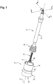
- FIG. 1 to 4 an individual egg transport device 10 and a gripping member 12 capable of gripping either an egg 14 or an individual egg transport device 10 are shown.
- the individual egg transport device 10 is in the form of a cup and has a generally cylindrical main body 16 with a main axis A1. It comprises an upper cup 18 designed to receive an egg 14, and in its lower part, a base 20 designed to ensure a stable position of the egg 14 on a conveyor element, for example when the individual device 10 is positioned on a conveyor belt.
- the base 20 may be provided to allow free movement of the individual device 10, either actively by means of the gripping member 12 which grips the individual device 10 and moves it from a first location to a second location, or passively by means of a particular arrangement on a conveyor belt for example, fixed storage bars (not shown) being able to allow the individual devices 10 to be recovered thanks to the relative movement of the conveyor belt with respect to the storage bars.
- the individual device 10 comprises a gripping element 22 allowing the gripping member 12 to grasp the individual device 10 by magnetic attraction to transport it from a first location to a second location.
- the individual device 10 here comprises at least one magnet 24 arranged in the bottom of a barrel 26 arranged in the main body 16.
- the main body 16 of the individual device 10 comprises in its upper section a truncated cone-shaped bore which forms a receptacle 28, or cup 18, for an egg 14.
- the barrel 26 or cylindrical bore is arranged to receive the magnet 24 forming a gripping element 22.
- the gripping element 22 here comprises two magnets 24 axially superimposed. Each magnet 24 has for example the shape of a washer coaxial with the axis A1 of the individual device 10.
- a lower cover 30 is fixed on the lower face of the main body 16. This cover 30 closes the barrel 26 and retains the magnets 24 in the bottom of the barrel 26.
- a spacer 32 may be provided between the cover 30 and the magnets 24 to prevent any movement of the magnets 24 in the barrel 26.
- the lower cover 30 here forms the base 20 of the individual device 10.
- metal parts here washers 34
- washers 34 are distributed circumferentially in a regular manner on the bottom of the cover 30.
- these are three metal washers 34, or pellets, which are screwed into the base 20.
- These three metal washers 34 here have diameters provided so that they cover the maximum of the lower surface 36 of the base 20.
- the main body 16 comprises a peripheral groove 38 around the entire periphery of the main body 16, here substantially at the same height as the upper magnet, in the vicinity of the base 20.
- the outer diameter of the base 20 and of the main body 16 up to the groove 38 is greater than the outer diameter of the upper part 40 of the main body 16, at the level of the upper cup 18 or of the receptacle 28.
- the gripping element 22 may be a metal part if the gripping member 12 comprises a magnet for gripping. According to another variant embodiment, the gripping element 22 and the gripping member 12 could each comprise a magnet to enable gripping by magnetic attraction.
- FIGS 1 to 4 also show the gripping member 12 according to the invention intended to grip the individual egg transport device 10 described above.
- the gripping member 12 comprises an arm 42 provided with a gripping rod 44 which is slidably mounted relative to the arm 42 in a main tube 46 along the main axis A1.
- the free end of the gripping rod 44 comprises a gripping tip 48 capable of gripping the individual device 10 by magnetic attraction.
- the gripping tip 48 here has the shape of a metal washer of diameter similar to the diameter of the magnets 24 arranged in the individual device 10, which allows the tip gripping tip 48 to grip the individual device 10 by means of the magnetic attraction exerted by the magnet 24 on the gripping tip 48.
- the figure 4 illustrates a position of the gripping member 12 when the gripping tip 48 grips the individual device 10 by magnetic attraction.
- the gripping tip 48 could comprise a magnet capable of cooperating with a metal washer arranged in the individual device 10.
- the gripping rod 44 is here mounted to slide freely axially in the main tube 46 of the arm 42.
- the upper axial end of the gripping rod 44 comprises a stop 50 of diameter greater than the rest of the gripping rod 44 so as to cooperate with a shoulder or narrowing 52 arranged inside the main tube 46 to axially retain the gripping rod 44 in an extreme low position. It is this position which is shown in the figures 1 , 2 , And 4 .
- the gripping rod 44 naturally occupies its low position under the effect of gravity since it is here mounted to slide freely in the arm 42.
- the arm 42 could be provided with a mechanism for controlling the axial position of the gripping rod 44 or an elastic return or damping element could be provided between the gripping rod 44 and the arm 42.
- the arm 42 comprises at its free end 54, or lower end, on the side of the gripping tip 48, a suction cup 56 coaxial with the gripping rod 44, capable of gripping an egg 14 by suction.
- the suction cup 56 here has the shape of a bellows which widens downwards to be able to adapt to different egg shapes.
- the gripping rod 44 is designed to slide axially through the suction cup 56.
- the suction cup 56 is connected to an air suction system 58 through the main tube 46, which allows the suction cup 56 to grip an egg 14 by suction, or depression.
- figure 3 shows the suction cup 56 in position on the top of an egg 14 for gripping.
- the sliding clearance of the gripping rod 44 in the arm 42 is sufficient to allow the air suction system 58 to create a depression in the suction cup 56 through the main tube 46.
- the gripping rod 44 is shown in its low position, with the gripping tip 48 positioned in the bottom of the receptacle 28 of the cup 18 so as to allow magnetic attraction between the gripping tip 48 and the magnets 24. In this position, the gripping tip 48 is therefore stuck against the bottom 60 of the receptacle 28 and the individual device 10 is therefore linked in movement to the gripping rod 44, therefore to the gripping member 12.
- the gripping member 12 and the individual device 10 form a unit for transporting eggs.
- FIG. 5 represents a mobile gripping shuttle 62 which comprises a multitude of gripping members 12 such as that which has just been described.
- This gripping shuttle 62 comprises a main plate 64, here of generally parallelepipedal shape, and the gripping members 12 are mounted on the main plate 64, on its lower face side.
- the gripping members 12 therefore extend parallel downwards in order to be able to grip a load of eggs 14 and/or a load of individual devices 10, by means of the suction cups 56 and the gripping tips 48 respectively.
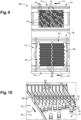
- the figure 6 partially represents the gripping shuttle 62 when a first gripping member 12 (on the left on the figure 6 ) is empty, that is to say that it does not carry any element and its gripping rod 44 occupies its extreme low position, when a second gripping member 12 (in the middle on the figure 6 ) grasps an egg 14 by suction using the suction cup 56, and when a third gripping member 12 (on the right on the figure 6 ) grips an individual device 10 by magnetic attraction by means of the gripping rod 44.
- the gripping shuttle 62 comprises N gripping members 12, these N gripping members 12 being capable of gripping up to N eggs 14 arranged either in N housings of an egg transport tray, or in N individual devices 10. These N gripping members 12 are also capable of gripping up to N individual devices 10.
- the main plate 64 comprises a system for adjusting the radial spacing 66 between the gripping members 12, which makes it possible to adapt the shape of the pattern drawn by the series of gripping members 12 to the arrangement of the housings of the egg transport tray and to the arrangement of the individual devices 10 arranged on a flat surface.
- the gripping shuttle 62 also includes a device for connecting the gripping members 12 to the air suction system 58 so as to be able to control the suction of the eggs 14 by the suction cups 56 of each gripping member 12.
- the air suction system 58 is also designed to be able to operate in reverse, which makes it possible to blow air through the suction cup 56 to unhook the eggs 14 when they have arrived at their destination.
- FIG 7 a variant of the gripping shuttle 62 of the figure 5 wherein the gripping members 12 are provided only for gripping individual devices 10 and not for gripping eggs 14.
- the gripping members 12 are similar to those described above except that they do not include a suction cup 56 and no connection to a source of air depression.
- This gripping shuttle 62 is only used for gripping and moving individual devices 10 without eggs.
- FIG 8 On the figure 8 an installation 68 for filling trays 70 for transporting eggs is shown, equipped with several gripping shuttles 62, here two, such as that of the figure 5 .
- This installation 68 comprises a first conveyor line 72, or main conveyor line, which is designed to supply the installation 68 with egg transport trays 70 comprising N housings 74 each capable of receiving an egg 14 in a vertical position.
- the trays 70 arrive in pairs.
- the invention also applies to the case where each tray 70 is treated individually and not in pairs.
- FIG 9 represents in its upper part a section of this first conveyor line 72 with two adjacent trays 70, here partially filled with eggs 14.
- the empty housings 74 are here represented in the form of a circle with a small circle inside, while the full housings 74, that is to say containing an egg 14, are represented in the form of a simple circle.
- the installation comprises a second conveyor line 76 which is provided for conveying individual devices 10 parallel to the first conveyor line 72, according to a second flow direction F2, also from left to right considering the figure 8 .
- This second conveyor line 76 here comprises a conveyor belt 77 which brings individual devices 10 placed in a disorderly manner to a first grouping station 78.
- the first grouping post 78 is illustrated by the lower part of the figure 9 and by the views of the Figures 10 to 13 . It is placed above the conveyor belt 77 and it comprises a series of longitudinal walls 80 parallel to the flow F2, and forming a number K of spokes 82. Each spoke 82 has a width substantially equal to the external diameter of an individual device 10. Thus, all the empty individual devices 10 arriving from upstream are directed towards the spokes 82 to form lines of individual devices 10.
- the first grouping station 78 comprises cleats 84, or blocking rakes, which retain downstream and upstream a first group G1 of individual devices 10 whose number corresponds to the number N of housings 74 on the egg transport trays 70.
- the installation 68 comprises a first gripping shuttle 62 which is mounted movably on a first gantry 86 so as to be able to move transversely T1 relative to the flows F1, F2.
- the first shuttle 62 makes it possible to grip the eggs 14 present on the transport trays 70 arriving on the first conveyor line 72, incomplete trays 70 forming a first load P1, and to transport them to the first group G1 of individual devices 10 where it deposits them.
- FIG 9 illustrates the first grouping station 78 when it is ready to receive the eggs 14 from the first conveyor line 72, the grouping having made it possible to create a first group G1 of individual devices 10 capable of receiving all the eggs 14 present on the two trays 70 of the first conveyor line 72.
- FIG 12 illustrates the first grouping station 78 after the first shuttle 62 has deposited all the captured eggs 14 in the corresponding individual devices 10. It is noted that the pattern described by the combination of empty individual devices 10 and full individual devices 10 corresponds here to the pattern of the trays 70 shown in the figure 9 since the gripping shuttle 62 simply took the eggs 14 from where they were and placed them in the same arrangement on the second conveyor line 76.
- the first gripping shuttle 62 By depositing the eggs 14 of the first load P1 in the first group G1 of individual devices 10, the first gripping shuttle 62 also grips the empty individual devices 10 in which no eggs 14 are deposited. Indeed, by moving downwards to delicately deposit each egg 14 in an individual device 10, by releasing the suction by the suction cups 56 with a slight overpressure of air, the gripping tips 48 also come into contact with the bottom of the receptacles 28 which causes the adhesion of the associated individual devices 10 by magnetic attraction.
- the first gripping shuttle 62 thus makes it possible to transport the empty individual devices 10 upstream of the second conveying line 76, here towards an intermediate feed station 87 upstream of the second conveying line 76 which is arranged parallel to the portion where the first grouping station 78 is arranged.
- This intermediate supply station 87 is here connected to the portion where the first grouping station 78 is arranged by a bend.
- FIG 13 represents the first grouping station 78 just after the empty individual devices 10 have been gripped by the first gripping shuttle 62. Note that there remain only individual devices 10 occupied by eggs 14 and empty spaces between them.
- the downstream cleat 84 is raised, allowing the remaining individual devices 10, all equipped with eggs 14, to pass through so that they move downstream, according to the second flow F2 thanks to the conveyor belt 77 which operates continuously.
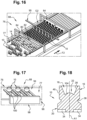
- FIG 14 illustrates the evacuation of the remaining individual devices 10 downstream.
- the individual devices 10 move with the conveyor belt 77 to be grouped downstream at a second grouping station 88.
- the second grouping post 88 which is illustrated in particular by the figure 15 , is similar to the first station 78 in its structure. It aims to allow the grouping of individual devices 10 which are all occupied by an egg 14. This second station 88 therefore makes it possible to form a second group G2 of individual devices 10 comprising N eggs in order to then be able to fill egg transport trays 70 comprising N housings 74.
- the installation 68 here comprises a second gripping shuttle 62 which is mounted movably on a second gantry 90 so as to be able to move transversely T2 relative to the flows F1, F2.
- the second gripping shuttle 62 makes it possible to grip the N eggs 14 present in the N individual devices 10 of the second group G2, and to transport them to the first conveyor line 72 and place them on empty egg transport trays 70 with N housings 74.
- the second gripping shuttle 62 is placed above the N eggs 14 of the second group G2, visible on the figure 15 , and lowers the gripping members 12 until the N suction cups 56 can come and grasp the N eggs 14 by suction to form a second load P2 of eggs 14.
- the second gripping shuttle 62 can then raise the gripping members 12 provided with the eggs 14 and move in the second transverse direction T2 to a depositing zone 92 of the first conveyor line 72 where two empty trays 70 are waiting. Arriving above the empty trays 70, the second gripping shuttle 62 deposits the N eggs 14 in the N housings 74 by lowering the gripping members 12 and releasing the suction in the suction cups 76, or even by applying slight air pressure in the suction cups 76 to unhook the eggs 14.
- the installation 68 thus provides, at the outlet of the first conveying line 72, trays 70 for transporting complete eggs which can be sent to a subsequent stage of treatment, incubation or to carry out any other operation on the trays 70 or on the eggs 14.
- the second gripping shuttle 62 can come and pick up the N empty individual devices 10, which are shown in the figure 16 , to then deposit them in an upstream feed zone 94 on the second conveyor line 76.
- the second gripping shuttle 62 it is sufficient for the second gripping shuttle 62 to bring the N gripping members 12 until the gripping tips 48 couple to the bottom of the receptacles 28 with the empty individual devices 10. Then the second gripping shuttle 62 rises and moves transversely T2 to the upstream feed zone 94.
- the first grouping station 78 and the second grouping station 88 each comprise a retractable spacing rake 95 which makes it possible to space the individual devices 10, and therefore the eggs 14, at the junction between the first and second halves of the eggs 14 which correspond respectively to the first and second trays 70 of the pair of trays 70.
- this spacing rake 95 is not necessary.
- a device 96 for unhooking the individual devices 10 is provided in the installation 68.
- the unhooking device 96 comprises forks 98 formed from parallel rods 100. These rods 100 are designed to be received tangentially in the peripheral grooves 38 of the individual devices 10 when a gripping shuttle 62 places them on the conveyor belt 77.
- the forks 98 make it possible to axially retain the individual devices 10 on the conveyor belt 77 when the gripping shuttle 62 rises with its gripping rods 44. This mechanism makes it possible to overcome the magnetic attraction exerted by the magnets 24 on the gripping tips 48.
- the forks 98 retract to allow the individual devices 10 to continue their movement with the conveyor belt 77 to the first grouping station 78.
- the unhooking device 96 comprises a magnetic plate 102 which is positioned under the conveyor belt 77 when a gripping shuttle 62 places the empty individual devices 10 on the conveyor belt 77.
- This magnetic plate 102 also makes it possible to overcome the magnetic attraction exerted by the magnets 24 on the gripping tips 48, by attracting the individual devices 10 downwards, which makes it possible to unhook the individual devices 10 from the gripping members 12.
- the magnetic plate 102 retracts to allow the individual devices 10 to continue their movement with the conveyor belt 77 to the first grouping station 78.
- the first conveyor line 72 can be dedicated to supplying incomplete egg transport trays 70, and a third conveyor line is provided to recover the second load of eggs and to remove trays 70 filled with eggs 14 in all the housings 74.
- This alternative embodiment makes it possible, for example, to supply the installation 68 with egg transport trays 70 comprising N housings 74 and to fill egg transport trays 70 comprising X housings 74 at the outlet, the number X of housings 74 possibly being equal to or different from the number N of housings 74 at the inlet.
- the second grouping station 88 is provided to form a second group G2 comprising X individual devices 10 filled with eggs 14.
- the first gantry 86 may comprise a third gripping shuttle 62 which makes it possible to transport the empty individual devices 10 remaining at the first grouping station 78 while the first gripping shuttle 62 collects and transports the eggs 14 from the first conveyor line 72 to the second conveyor line 76.
- the third gripping shuttle 62 is dedicated to the transfer of the empty individual devices 10 from the first grouping station 78 to the intermediate supply station 87, or third station.
- the upper cup 18 is provided in the bottom of the receptacle 28 with a surface provided for gripping by a suction cup 56, in addition to or replacing the magnet system 24.
- this surface is a boss 104, preferably smooth or polished.
- This boss 104 allows gripping of the individual device 10 by suction with the suction cup 56 used for gripping the eggs 14.
- the boss 104 here has the shape of a convex domed surface approaching the shape of an egg 14 to facilitate gripping of the individual device 10 by the same suction cup 56 as that provided for gripping an egg 14.
- the gripping member 12 only comprises the suction cup 56, but can also comprise both the suction cup 56 and the magnet with the gripping rod 44.
- the gripping member 12 can therefore grip either an empty individual device 10 or an egg 14 and the gripping shuttle 62 can therefore grip both empty individual devices 10 and eggs 14, but also distinctly eggs 14 or empty individual devices 10, depending on the choice of whether or not to suck on each suction cup 56.
- the difference between this variant embodiment and the main embodiment described above lies in the management of the automatic control of the gripping members 12: the version with boss 104 requires individual management for the gripping, movement, and removal of each individual device 10. Indeed, the gripping shuttle 62 and the control of the suction system 58 must be able to determine which gripping members 12 are equipped with individual devices 10 to be released and which gripping members 12 carry eggs 14.
- An advantage of the solution with magnet shown above is that the management of the automation to control the gripping and the movement of the gripping shuttle 62 is simpler since the individual devices 10 are only gripped by the gripping members 12 if they are empty, whereas if they are full, the gripping members 12 can only grip the eggs 14 if a suction is commanded through the suction cup 56.
- the installation 68 and of the filling method according to the invention it is possible to detect upon arrival on the first conveyor line 72 whether trays 70 are very full, for example filled to more than 75%, and in this case not to empty them. It is then provided to form on the second conveyor line 78, with an adequate arrangement of the eggs 14 in the individual devices 10, an egg filling pattern which makes it possible to complete the very full trays 70 on the first conveyor line 72 by depositing the eggs 14 by means of the second gripping shuttle 62 only in the empty housings 74 of the trays 70.
- the individual device 10, the installation 68, and the filling method according to the invention allow the additional filling of egg transport trays 70 by making it possible to complete partially filled trays 70 with eggs 14 so that all the housings 74 of the tray 70 are occupied at the outlet of the conveyor line.
Landscapes
- Life Sciences & Earth Sciences (AREA)
- Environmental Sciences (AREA)
- Engineering & Computer Science (AREA)
- Mechanical Engineering (AREA)
- Animal Husbandry (AREA)
- Biodiversity & Conservation Biology (AREA)
- Birds (AREA)
- Wrapping Of Specific Fragile Articles (AREA)
- Specific Conveyance Elements (AREA)
Claims (15)
- Eier-Einzeltransportvorrichtung (10), umfassend:- einen oberen Becher (18), der zur Aufnahme eines Eis (14) bestimmt ist,- eine Basis (20), die dazu vorgesehen ist, eine stabile Position des oberen Bechers (18) auf einem Förderelement (77) zu gewährleisten,dadurch gekennzeichnet, dass sie Folgendes umfasst:- ein Greifelement (22), das es einem Greiforgan (12) ermöglicht, die Einzelvorrichtung (10) zu erfassen, um sie von einem ersten Ort zu einem zweiten Ort zu transportieren.
- Einzelvorrichtung (10) nach dem vorstehenden Anspruch,
dadurch gekennzeichnet, dass das Greifelement (22) einen Magneten (24) oder ein Metallteil umfasst, der/das unter dem oberen Becher (18) eingerichtet ist, um es dem Greiforgan (12) zu ermöglichen, die Einzelvorrichtung (10) durch magnetische Anziehung zu erfassen. - Einzelvorrichtung (10) nach einem der vorstehenden Ansprüche,
dadurch gekennzeichnet, dass sie eine Oberfläche wie einen Vorsprung (104) umfasst, der das Greifen der Einzelvorrichtung durch einen Saugnapf (56) ermöglicht. - Einzelvorrichtung (10) nach einem der vorstehenden Ansprüche,
dadurch gekennzeichnet, dass sie eine umlaufende Rille (38) umfasst. - Einzelvorrichtung (10) nach einem der vorstehenden Ansprüche,
dadurch gekennzeichnet, dass die Basis (20) Metallpads (34) umfasst, die auf der Unterseite der Basis (20) verteilt sind. - Greiforgan (12) zum Erfassen einer Eier-Einzeltransportvorrichtung (10) nach einem der vorstehenden Ansprüche, dadurch gekennzeichnet, dass es einen Arm (42) umfasst, der mit einer Greifstange (44) versehen ist, die relativ zum Arm gleitend montiert ist (42), dadurch, dass das freie Ende der Greifstange (44) einen Greifeinsatz (48) umfasst, der in der Lage ist, die Einzelvorrichtung (10) durch magnetische Anziehung zu erfassen, und dadurch, dass der Arm (42) an seinem freien Ende auf der Seite des Greifeinsatzes (48) einen Saugnapf (56) koaxial zur Greifstange (44) umfasst, der in der Lage ist, ein Ei (14) durch Ansaugen zu erfassen.
- Greiforgan (12) nach dem vorstehenden Anspruch,
dadurch gekennzeichnet, dass die Greifstange (44) frei gleitend im Arm (42) montiert ist. - Anordnung zum Transport von Eiern, dadurch gekennzeichnet, dass sie ein Greiforgan (12) nach einem der Ansprüche 6 oder 7 und eine Einzelvorrichtung (10) nach einem der Ansprüche 1 bis 5 umfasst.
- Greifshuttle (62), dadurch gekennzeichnet, dass es mindestens N Greiforgane (12) nach Anspruch 6 oder 7 umfasst, wobei diese N Greiforgane (12) in der Lage sind, bis zu N Eier (14) zu erfassen, die entweder in N Aufnahmen (74) einer Eiertransportpalette (70), oder in N Einzelvorrichtungen (10) nach einem der Ansprüche 1 bis 5 angeordnet sind.
- Anlage (68) zum Befüllen von Eiertransportpaletten (70),
dadurch gekennzeichnet, dass sie umfasst:- eine erste Förderstrecke (72), die dazu bestimmt ist, die Anlage (68) mit Eiertransportpaletten (70) zu beschicken, die N Aufnahmen (74) umfassen, die in der Lage sind, jeweils ein Ei (14) in vertikaler Position aufzunehmen,- eine zweite Förderstrecke (76), die zum Fördern von Einzelvorrichtungen (10) nach einem der Ansprüche 1 bis 5 bestimmt ist,- eine dritte Förderstrecke, die dazu bestimmt ist, die Eiertransportpaletten (70), die X Aufnahmen (74) umfassen, die jeweils ein Ei (14) in vertikaler Position aufnehmen können, auszuschleusen- mindestens ein Greifshuttle (62) nach Anspruch 9, das zwischen der ersten Förderstrecke (72) und der zweiten Förderstrecke (76) verfahrbar ist, um in der Lage zu sein:-- in einem ersten Schritt eine erste Ladung (P1) Eier auf einer ersten Palette (70) zu erfassen, die eine Anzahl von Eiern M kleiner als N umfasst, die erste Ladung (P1) Eier zur zweiten Förderstrecke (76) zu transportieren, die erste Ladung (P1) Eier in einer ersten Gruppe (G1) von Einzelvorrichtungen (10) abzulegen,-- in einem zweiten Schritt eine zweite Ladung (P2) Eier zu erfassen, die in einer zweiten Gruppe (G2) von Einzelvorrichtungen (10) angeordnet sind, die auf der zweiten Förderstrecke (76) eingerichtet ist, die zweite Ladung (P2) Eier zu einer dritten Hauptförderstrecke zu transportieren, die zweite Ladung (P2) Eier in den Aufnahmen (74) einer Palette (70) abzulegen, die X Aufnahmen (74) umfasst. - Anlage (68) nach dem vorstehenden Anspruch,
dadurch gekennzeichnet, dass die zweite Förderstrecke (76) eine erste dem Förderstrom (F2) vorgelagerte Station (78) umfasst, an der die Einzelvorrichtungen (10) zur Bildung der ersten Gruppe (G1) gruppiert werden, und eine dem Förderstrom (F2) nachgelagerte zweite Station (88), an der die Einzelvorrichtungen (10) zur Bildung der zweiten Gruppe (G2) gruppiert werden. - Anlage (68) nach dem vorstehenden Anspruch,
dadurch gekennzeichnet, dass sie ein erstes Greifshuttle (62) nach Anspruch 9 umfasst, das die erste Ladung (P1) Eier transportiert, und ein zweites Greifshuttle (62) nach Anspruch 9, das zwischen der ersten Station (78) und einer relativ zur ersten Station (78) vorgelagerten dritten Station (87) verfahrbar ist, um die leeren Einzelvorrichtungen (10) der ersten Gruppe (G1) von der ersten Station (78) zur dritten Station (87) transportieren zu können. - Anlage (68) nach dem vorstehenden Anspruch,
dadurch gekennzeichnet, dass sie ein drittes Greifshuttle (62) nach Anspruch 9 umfasst, das die zweite Ladung (P2) Eier transportiert. - Anlage (68) nach einem der Ansprüche 10 bis 13,
dadurch gekennzeichnet, dass die erste Förderstrecke (72) und die dritte Förderstrecke eine einzige Hauptförderstrecke (72) bilden und dadurch, dass die Anzahl N der Aufnahmen (74) gleich der Anzahl X der Aufnahmen (74) ist. - Verfahren zum Befüllen von Eiertransportpaletten (70),
dadurch gekennzeichnet, dass es folgende Schritte umfasst:- Beschicken einer ersten Förderstrecke (72) mit Eiertransportpaletten (70), die N Aufnahmen (74) umfassen, die in der Lage sind, jeweils ein Ei (14) in vertikaler Position aufzunehmen,- Beschicken einer zweiten Förderstrecke (76) mit Einzelvorrichtungen (10) nach einem der Ansprüche 1 bis 5,- einen ersten Schritt zum Transport einer ersten Ladung (P1) Eier mit dem Greifshuttle (62) nach Anspruch 9 von einer ersten Palette (70) der ersten Förderstrecke (72) zu einer ersten Gruppe (G1) von Einzelvorrichtungen (10), die auf der zweiten Förderstrecke (76) platziert ist,- einen Gruppierungsschritt, bei dem die Einzelvorrichtungen (10) zu einer zweiten Gruppe (G2) von Einzelvorrichtungen (10) auf der zweiten Förderstrecke (76) gruppiert werden,- einen zweiten Schritt zum Transport einer zweiten Ladung (P2) Eier, die in der zweiten Gruppe (G2) von Einzelvorrichtungen (10) angeordnet sind, zu einer Palette (70), die X Aufnahmen (74) auf der dritten Förderstrecke umfasst.
Applications Claiming Priority (3)
| Application Number | Priority Date | Filing Date | Title |
|---|---|---|---|
| FR2012652A FR3116992A1 (fr) | 2020-12-03 | 2020-12-03 | Dispositif individuel de transport d’œuf, installation et procédé utilisant un tel dispositif |
| FR2100126A FR3116991B1 (fr) | 2020-12-03 | 2021-01-07 | Dispositif individuel de transport d’œuf, installation de remplissage complémentaire et procédé associé |
| PCT/FR2021/052083 WO2022117933A1 (fr) | 2020-12-03 | 2021-11-24 | DISPOSITIF INDIVIDUEL DE TRANSPORT D'œUF, INSTALLATION DE REMPLISSAGE COMPLÉMENTAIRE ET PROCÉDÉ ASSOCIÉ |
Publications (3)
| Publication Number | Publication Date |
|---|---|
| EP4255178A1 EP4255178A1 (de) | 2023-10-11 |
| EP4255178C0 EP4255178C0 (de) | 2024-09-25 |
| EP4255178B1 true EP4255178B1 (de) | 2024-09-25 |
Family
ID=79021183
Family Applications (1)
| Application Number | Title | Priority Date | Filing Date |
|---|---|---|---|
| EP21830450.9A Active EP4255178B1 (de) | 2020-12-03 | 2021-11-24 | Individuelle eitransportvorrichtung, komplementäre füllanlage und zugehöriges verfahren |
Country Status (3)
| Country | Link |
|---|---|
| US (1) | US20240010446A1 (de) |
| EP (1) | EP4255178B1 (de) |
| WO (1) | WO2022117933A1 (de) |
Family Cites Families (2)
| Publication number | Priority date | Publication date | Assignee | Title |
|---|---|---|---|---|
| NL8202980A (nl) * | 1982-07-23 | 1984-02-16 | Staalkat Bv | Transporteur voorzien van houders. |
| CA3082373A1 (en) * | 2017-11-14 | 2019-05-23 | Seleggt Gmbh | Egg support and apparatus for handling eggs |
-
2021
- 2021-11-24 US US18/255,851 patent/US20240010446A1/en active Pending
- 2021-11-24 WO PCT/FR2021/052083 patent/WO2022117933A1/fr not_active Ceased
- 2021-11-24 EP EP21830450.9A patent/EP4255178B1/de active Active
Also Published As
| Publication number | Publication date |
|---|---|
| EP4255178A1 (de) | 2023-10-11 |
| EP4255178C0 (de) | 2024-09-25 |
| WO2022117933A1 (fr) | 2022-06-09 |
| US20240010446A1 (en) | 2024-01-11 |
Similar Documents
| Publication | Publication Date | Title |
|---|---|---|
| FR2897341A1 (fr) | Procede et installation pour le groupage de produits palettisables. | |
| EP2196395B1 (de) | Vorrichtung und Verfahren zur Verpackung von Spritzen in Nestern | |
| EP2032443B1 (de) | Anlage zur verpackung von objekten wie zum beispiel flaschen verschiedener ausführung | |
| WO2011086278A1 (fr) | Procede et machine de suremballage d'articles pour former des lots d'articles, du type comprenant une certaine pluralite d'articles et un suremballage en carton | |
| US20130148076A1 (en) | Suction gripper and manipulation system for ophthalmic lenses | |
| EP4255178B1 (de) | Individuelle eitransportvorrichtung, komplementäre füllanlage und zugehöriges verfahren | |
| EP2367650A1 (de) | Transport- und lagerungsvorrichtung für ein giesspfannenrohr zum weiterleiten von flüssigem metall | |
| FR3116991A1 (fr) | Dispositif individuel de transport d’œuf, installation de remplissage complémentaire et procédé associé | |
| BE1012756A3 (fr) | Procede et dispositif pour la fabrication de brosses. | |
| BE1005360A3 (fr) | Systeme d'alimentation d'un metier en fil de trame. | |
| EP4262348B1 (de) | Maschine zum pflanzen von zwiebeln in einer vorbestimmten position | |
| EP2920092A2 (de) | Maschine mit schüttgutzuführung zum verteilen von gegenständen | |
| CN116709912A (zh) | 蛋输送单个装置、补充填装设备及相关方法 | |
| FR2582242A1 (fr) | Installation d'alimentation et d'evacuation automatique en series de pieces d'un ensemble de postes de travail | |
| EP4457037B1 (de) | Paketsortierverfahren zur beschickung eines injektionsförderers von einem einziehbaren zuführförderer und paketsortieranlage zur durchführung eines solchen verfahrens | |
| EP0021988B1 (de) | Verfahren und Vorrichtung zum Entladen von Flaschen | |
| FR2998272A1 (fr) | Installation et procede d'emballage de fruits ou legumes | |
| FR3056971A1 (fr) | Deplacement de produits dans une ligne | |
| BE1014460A3 (fr) | Installation pour la fabrication de brosses. | |
| FR3154387A1 (fr) | Procede de preparation de commandes | |
| BE1014587A3 (fr) | Machine de fabrication de brosses. | |
| FR2730129A1 (fr) | Dispositif de retournement de fromages transportes sur des claies | |
| FR3115275A1 (fr) | Installation de chargement automatique de sachets dans une boîte | |
| FR3075187A1 (fr) | Installation de tri et d'appariement d'un train de produits identifies | |
| FR3053772A1 (fr) | Secheur industriel ameliore pour poches plastiques |
Legal Events
| Date | Code | Title | Description |
|---|---|---|---|
| STAA | Information on the status of an ep patent application or granted ep patent |
Free format text: STATUS: UNKNOWN |
|
| STAA | Information on the status of an ep patent application or granted ep patent |
Free format text: STATUS: THE INTERNATIONAL PUBLICATION HAS BEEN MADE |
|
| PUAI | Public reference made under article 153(3) epc to a published international application that has entered the european phase |
Free format text: ORIGINAL CODE: 0009012 |
|
| STAA | Information on the status of an ep patent application or granted ep patent |
Free format text: STATUS: REQUEST FOR EXAMINATION WAS MADE |
|
| 17P | Request for examination filed |
Effective date: 20230607 |
|
| AK | Designated contracting states |
Kind code of ref document: A1 Designated state(s): AL AT BE BG CH CY CZ DE DK EE ES FI FR GB GR HR HU IE IS IT LI LT LU LV MC MK MT NL NO PL PT RO RS SE SI SK SM TR |
|
| DAV | Request for validation of the european patent (deleted) | ||
| DAX | Request for extension of the european patent (deleted) | ||
| GRAP | Despatch of communication of intention to grant a patent |
Free format text: ORIGINAL CODE: EPIDOSNIGR1 |
|
| STAA | Information on the status of an ep patent application or granted ep patent |
Free format text: STATUS: GRANT OF PATENT IS INTENDED |
|
| INTG | Intention to grant announced |
Effective date: 20240524 |
|
| GRAS | Grant fee paid |
Free format text: ORIGINAL CODE: EPIDOSNIGR3 |
|
| GRAA | (expected) grant |
Free format text: ORIGINAL CODE: 0009210 |
|
| STAA | Information on the status of an ep patent application or granted ep patent |
Free format text: STATUS: THE PATENT HAS BEEN GRANTED |
|
| AK | Designated contracting states |
Kind code of ref document: B1 Designated state(s): AL AT BE BG CH CY CZ DE DK EE ES FI FR GB GR HR HU IE IS IT LI LT LU LV MC MK MT NL NO PL PT RO RS SE SI SK SM TR |
|
| REG | Reference to a national code |
Ref country code: GB Ref legal event code: FG4D Free format text: NOT ENGLISH |
|
| REG | Reference to a national code |
Ref country code: CH Ref legal event code: EP |
|
| REG | Reference to a national code |
Ref country code: DE Ref legal event code: R096 Ref document number: 602021019425 Country of ref document: DE |
|
| REG | Reference to a national code |
Ref country code: IE Ref legal event code: FG4D Free format text: LANGUAGE OF EP DOCUMENT: FRENCH |
|
| RAP4 | Party data changed (patent owner data changed or rights of a patent transferred) |
Owner name: NECTRA |
|
| U01 | Request for unitary effect filed |
Effective date: 20241003 |
|
| U07 | Unitary effect registered |
Designated state(s): AT BE BG DE DK EE FI FR IT LT LU LV MT NL PT RO SE SI Effective date: 20241028 |
|
| PG25 | Lapsed in a contracting state [announced via postgrant information from national office to epo] |
Ref country code: NO Free format text: LAPSE BECAUSE OF FAILURE TO SUBMIT A TRANSLATION OF THE DESCRIPTION OR TO PAY THE FEE WITHIN THE PRESCRIBED TIME-LIMIT Effective date: 20241225 |
|
| PG25 | Lapsed in a contracting state [announced via postgrant information from national office to epo] |
Ref country code: GR Free format text: LAPSE BECAUSE OF FAILURE TO SUBMIT A TRANSLATION OF THE DESCRIPTION OR TO PAY THE FEE WITHIN THE PRESCRIBED TIME-LIMIT Effective date: 20241226 |
|
| PG25 | Lapsed in a contracting state [announced via postgrant information from national office to epo] |
Ref country code: RS Free format text: LAPSE BECAUSE OF FAILURE TO SUBMIT A TRANSLATION OF THE DESCRIPTION OR TO PAY THE FEE WITHIN THE PRESCRIBED TIME-LIMIT Effective date: 20241225 |
|
| PG25 | Lapsed in a contracting state [announced via postgrant information from national office to epo] |
Ref country code: RS Free format text: LAPSE BECAUSE OF FAILURE TO SUBMIT A TRANSLATION OF THE DESCRIPTION OR TO PAY THE FEE WITHIN THE PRESCRIBED TIME-LIMIT Effective date: 20241225 Ref country code: NO Free format text: LAPSE BECAUSE OF FAILURE TO SUBMIT A TRANSLATION OF THE DESCRIPTION OR TO PAY THE FEE WITHIN THE PRESCRIBED TIME-LIMIT Effective date: 20241225 Ref country code: GR Free format text: LAPSE BECAUSE OF FAILURE TO SUBMIT A TRANSLATION OF THE DESCRIPTION OR TO PAY THE FEE WITHIN THE PRESCRIBED TIME-LIMIT Effective date: 20241226 |
|
| U20 | Renewal fee for the european patent with unitary effect paid |
Year of fee payment: 4 Effective date: 20250120 |
|
| PG25 | Lapsed in a contracting state [announced via postgrant information from national office to epo] |
Ref country code: IS Free format text: LAPSE BECAUSE OF FAILURE TO SUBMIT A TRANSLATION OF THE DESCRIPTION OR TO PAY THE FEE WITHIN THE PRESCRIBED TIME-LIMIT Effective date: 20250125 |
|
| PG25 | Lapsed in a contracting state [announced via postgrant information from national office to epo] |
Ref country code: SM Free format text: LAPSE BECAUSE OF FAILURE TO SUBMIT A TRANSLATION OF THE DESCRIPTION OR TO PAY THE FEE WITHIN THE PRESCRIBED TIME-LIMIT Effective date: 20240925 |
|
| PG25 | Lapsed in a contracting state [announced via postgrant information from national office to epo] |
Ref country code: ES Free format text: LAPSE BECAUSE OF FAILURE TO SUBMIT A TRANSLATION OF THE DESCRIPTION OR TO PAY THE FEE WITHIN THE PRESCRIBED TIME-LIMIT Effective date: 20240925 |
|
| PG25 | Lapsed in a contracting state [announced via postgrant information from national office to epo] |
Ref country code: CZ Free format text: LAPSE BECAUSE OF FAILURE TO SUBMIT A TRANSLATION OF THE DESCRIPTION OR TO PAY THE FEE WITHIN THE PRESCRIBED TIME-LIMIT Effective date: 20240925 Ref country code: PL Free format text: LAPSE BECAUSE OF FAILURE TO SUBMIT A TRANSLATION OF THE DESCRIPTION OR TO PAY THE FEE WITHIN THE PRESCRIBED TIME-LIMIT Effective date: 20240925 |
|
| PG25 | Lapsed in a contracting state [announced via postgrant information from national office to epo] |
Ref country code: SK Free format text: LAPSE BECAUSE OF FAILURE TO SUBMIT A TRANSLATION OF THE DESCRIPTION OR TO PAY THE FEE WITHIN THE PRESCRIBED TIME-LIMIT Effective date: 20240925 |
|
| REG | Reference to a national code |
Ref country code: CH Ref legal event code: PL |
|
| PG25 | Lapsed in a contracting state [announced via postgrant information from national office to epo] |
Ref country code: MC Free format text: LAPSE BECAUSE OF FAILURE TO SUBMIT A TRANSLATION OF THE DESCRIPTION OR TO PAY THE FEE WITHIN THE PRESCRIBED TIME-LIMIT Effective date: 20240925 |
|
| REG | Reference to a national code |
Ref country code: CH Ref legal event code: PL |
|
| PG25 | Lapsed in a contracting state [announced via postgrant information from national office to epo] |
Ref country code: CH Free format text: LAPSE BECAUSE OF NON-PAYMENT OF DUE FEES Effective date: 20241130 |
|
| PLBE | No opposition filed within time limit |
Free format text: ORIGINAL CODE: 0009261 |
|
| STAA | Information on the status of an ep patent application or granted ep patent |
Free format text: STATUS: NO OPPOSITION FILED WITHIN TIME LIMIT |
|
| 26N | No opposition filed |
Effective date: 20250626 |
|
| PG25 | Lapsed in a contracting state [announced via postgrant information from national office to epo] |
Ref country code: IE Free format text: LAPSE BECAUSE OF NON-PAYMENT OF DUE FEES Effective date: 20241124 |