EP4253696B1 - Vorrichtung zur aufnahme von flächenelementen - Google Patents
Vorrichtung zur aufnahme von flächenelementen Download PDFInfo
- Publication number
- EP4253696B1 EP4253696B1 EP22165145.8A EP22165145A EP4253696B1 EP 4253696 B1 EP4253696 B1 EP 4253696B1 EP 22165145 A EP22165145 A EP 22165145A EP 4253696 B1 EP4253696 B1 EP 4253696B1
- Authority
- EP
- European Patent Office
- Prior art keywords
- longitudinal groove
- fence post
- longitudinal
- post profile
- profile
- Prior art date
- Legal status (The legal status is an assumption and is not a legal conclusion. Google has not performed a legal analysis and makes no representation as to the accuracy of the status listed.)
- Active
Links
Images


Classifications
-
- E—FIXED CONSTRUCTIONS
- E04—BUILDING
- E04H—BUILDINGS OR LIKE STRUCTURES FOR PARTICULAR PURPOSES; SWIMMING OR SPLASH BATHS OR POOLS; MASTS; FENCING; TENTS OR CANOPIES, IN GENERAL
- E04H17/00—Fencing, e.g. fences, enclosures, corrals
- E04H17/14—Fences constructed of rigid elements, e.g. with additional wire fillings or with posts
- E04H17/16—Fences constructed of rigid elements, e.g. with additional wire fillings or with posts using prefabricated panel-like elements, e.g. wired frames
- E04H17/168—Fences constructed of rigid elements, e.g. with additional wire fillings or with posts using prefabricated panel-like elements, e.g. wired frames using panels fitted in grooves of posts
-
- E—FIXED CONSTRUCTIONS
- E04—BUILDING
- E04H—BUILDINGS OR LIKE STRUCTURES FOR PARTICULAR PURPOSES; SWIMMING OR SPLASH BATHS OR POOLS; MASTS; FENCING; TENTS OR CANOPIES, IN GENERAL
- E04H17/00—Fencing, e.g. fences, enclosures, corrals
- E04H17/14—Fences constructed of rigid elements, e.g. with additional wire fillings or with posts
- E04H17/1413—Post-and-rail fences, e.g. without vertical cross-members
- E04H17/1447—Details of connections between rails and posts
- E04H17/1452—Details of connections between rails and posts the ends of the rails are fixed on the lateral sides of the posts
- E04H17/1456—Details of connections between rails and posts the ends of the rails are fixed on the lateral sides of the posts the ends of the rails being located in vertical channels extending along a substantial portion of the length of the post
-
- E—FIXED CONSTRUCTIONS
- E04—BUILDING
- E04H—BUILDINGS OR LIKE STRUCTURES FOR PARTICULAR PURPOSES; SWIMMING OR SPLASH BATHS OR POOLS; MASTS; FENCING; TENTS OR CANOPIES, IN GENERAL
- E04H17/00—Fencing, e.g. fences, enclosures, corrals
- E04H17/14—Fences constructed of rigid elements, e.g. with additional wire fillings or with posts
- E04H17/1413—Post-and-rail fences, e.g. without vertical cross-members
- E04H17/1447—Details of connections between rails and posts
- E04H17/1488—Brackets for connections between rails and posts
-
- E—FIXED CONSTRUCTIONS
- E04—BUILDING
- E04H—BUILDINGS OR LIKE STRUCTURES FOR PARTICULAR PURPOSES; SWIMMING OR SPLASH BATHS OR POOLS; MASTS; FENCING; TENTS OR CANOPIES, IN GENERAL
- E04H17/00—Fencing, e.g. fences, enclosures, corrals
- E04H17/14—Fences constructed of rigid elements, e.g. with additional wire fillings or with posts
- E04H17/20—Posts therefor
- E04H17/21—Posts therefor with hollow cross sections
Definitions
- the invention relates to a device according to claim 1 for receiving surface elements for producing a fence, comprising a fence post profile which has on at least one side a first longitudinal groove extending over its length, the longitudinal opening of which is tapered, whereby an undercut is formed.
- the profile rails have a rectangular cross-section and are provided with longitudinal grooves on their sides into which the fence slats are inserted.
- the profile rails form the fence posts.
- the slats are fixed in the longitudinal grooves of the profiles using inserted sliding blocks.
- Such a fence system is used, for example, in the DE 202016106503 U1
- Further devices according to the state of the art for receiving surface elements are also described in KR101910532B1 , FR3032003A1 , GB1404982A and DE202005003011U1 revealed.
- the invention aims to remedy this situation.
- the invention is based on the object of providing a device for receiving surface elements for the production of a fence, which allows for a more variable fence profile. According to the invention, this object is achieved by a device having the features of the characterizing part of patent claim 1.
- the invention provides a device according to claim 1 for receiving surface elements for producing a fence, which device allows for a more variable fence configuration. Because at least one first longitudinal groove accommodates an insert that has a second longitudinal groove for receiving a surface element and is pivotable about its longitudinal axis in the first longitudinal groove, a pivotable connection is created between the surface element and the fence post profile, thereby enabling a variable fence configuration.
- the first longitudinal groove has a circular arc-shaped cross-section whose arc spans an angle of greater than 200°, with the insert being cylindrical in shape. This allows the insert to pivot in the longitudinal groove in the manner of a hinge.
- the insert has a circular arc-shaped cross-section due to the second longitudinal groove, which spans an angle of greater than 200°, preferably greater than 240°, and is designed such that it can be inserted into the first groove from the front in a direction orthogonal to the longitudinal axis of the fence post profile in a pivoted position, where it can be radially fixed after pivoting about its longitudinal axis.
- This enables simple installation of the insert in the first groove.
- the design of the insert formed by the second longitudinal groove enables the insert to be inserted into the first longitudinal groove in a specific pivoted position, which cannot be assumed after the surface element has been installed.
- the second longitudinal groove has a substantially C-shaped cross-section. This allows the insertion of surface elements with a rectangular cross-section at the end.
- an elastic sealing element is arranged at least partially on at least two opposite side walls of the second longitudinal groove. This enables a clamping insertion of a surface element into the second longitudinal groove, allowing the surface element to be mounted in the insert without tools by simply inserting it.
- the elastic sealing element is inserted into a recess arranged in the side wall.
- This allows sealing elements of different thicknesses to be used depending on the material thickness of the surface element to be used.
- the elastic sealing element can also be injection-molded or glued onto the side wall. Injection-molded sealing elements are suitable for the manufacture of the insert using a plastic injection molding process, where they are injected onto the base material, particularly as an additional material, preferably an elastomer material.
- locking grooves are formed in the side walls opposite at least one first longitudinal groove of the fence post profile.
- a cover profile is provided which, for closing the longitudinal groove, can be locked into the locking grooves of the first longitudinal groove of the fence post profile via locking strips. This allows for tool-free closing of the longitudinal groove.
- the fence post profile is essentially cuboid-shaped and preferably made of metal, in particular aluminum. This enables cost-effective production, particularly using the extrusion process.
- a stop piece is arranged in at least one first longitudinal groove, which stop piece is continuously longitudinally displaceable therein and can be fixed in a longitudinal position via a clamping means, preferably a clamping screw.
- a clamping means preferably a clamping screw.
- the stop piece essentially fills the cross-section of the longitudinal groove.
- the fence post profile is closed at one end by a cover plate arranged axially to close the existing first longitudinal grooves. This ensures axial securing of the inserted inserts.
- a preferably elastic pressure piece is arranged in at least one first longitudinal groove, which is connected to the cover plate via a clamping means, preferably a threaded rod.
- the fence post profile has a central channel along its central longitudinal axis.
- a ground anchor is provided, With a plug-in profile that can be inserted into the central channel to secure the fence post profile, with its outer contour essentially corresponding to the inner contour of the central channel. This allows the fence post profile to be attached by sliding it onto the ground anchor, creating a positive connection between the central channel and the plug-in profile.
- the fence section selected as an exemplary embodiment, mounted with a device according to the invention for receiving surface elements comprises a fence post profile 1 provided with longitudinal grooves 11 in which inserts 2 are pivotably arranged, which are held axially between a stop piece 3 and a pressure piece 4 and which has a second longitudinal groove 21 for receiving a surface element 8.
- the fence post profile 1 is closed at one end by a cover plate 5, to which a hood 6 is applied.
- a surface element 8 designed as a panel is inserted into each of the inserts 2 of a first longitudinal groove 11 of the fence post profile 1, thereby forming a closed fence surface.
- the fence post profile 1 is fastened via a ground anchor 9, which projects into the ground.
- Figure 2 The device is shown in a simplified form with a shortened fence post profile 1, in whose longitudinal grooves 11 only one insert 2 is inserted.
- the fence post profile 1 is designed as an extruded aluminum hollow profile with a substantially square cross-section.
- the fence post profile 1 On three longitudinal sides, the fence post profile 1 has a first longitudinal groove 11 in the center, which extends over its entire length and has a circular arc-shaped cross-section spanning an angle of 240°, whereby an undercut 111 is formed on both sides of its longitudinal opening.
- the fourth side is closed.
- Two axial locking grooves 12 are inserted opposite one another in the first longitudinal grooves and extend over the entire length of the first longitudinal grooves 11.
- the longitudinal grooves 11 delimit a central channel 13, which has a square cross-section and extends along the central axis of the fence post profile 1.
- the insert 2 is cylindrical and, in the exemplary embodiment, is manufactured as a plastic injection-molded part.
- a second longitudinal groove 21 is formed in the outer surface of the insert 2 and extends over the entire length of the insert 2.
- the second longitudinal groove 21 merges radially into a widened section 22 with a rectangular cross-section, whereby the inner contour of a C-profile. Due to the second longitudinal groove 21, the insert 2 has an arcuate cross-section spanning an angle of 220°.
- a receptacle 23 for a sealing element 24 is formed in each of the three side walls of the widened section 22 of the second longitudinal groove 21.
- the receptacle 23 comprises a longitudinal groove 231, from the base of which an incision 232 extends, forming an undercut.
- the stop piece 3 is designed in the shape of a cylindrical segment and has an outer surface that corresponds to the inner surface of the first longitudinal groove 11 of the fence post profile 1, into which it can be inserted. Due to its cylindrical segment-shaped design, the stop piece 3 can be inserted from the front in a direction orthogonal to the longitudinal axis of the fence post profile 1 in a pivoted position into the first longitudinal groove 11, where, after pivoting about its longitudinal axis, it rests against the undercut 111 and is thus radially fixed.
- a radial threaded bore 31 is arranged, into which a grub screw (not shown) is screwed, which can be clamped against the fence post profile 1.
- the threaded bore 31 can be closed by a cover plug 32.
- the pressure piece 4 comprises a substantially cylindrical pressure body 41, which is centrally provided with a threaded rod 42, with which it is screwed into a threaded bore 51 provided for this purpose in the cover plate 5.
- the outer diameter of the pressure body 41 is smaller than the inner diameter of the first longitudinal groove 11 of the fence post profile 1.
- the threaded rod 42 is rotatable but axially fixed in the pressure body 41.
- a slot (not shown) for the engagement of a screwdriver is introduced into the threaded rod 42.
- the pressure body 41 is axially movable in the first longitudinal groove 11 of the fence post profile 1.
- the pressure body 41 is made of plastic, preferably of an elastomer plastic.
- the cover plate 5 is essentially square and has an outer contour that corresponds to the outer contour of the cross section of the fence post profile 1.
- Four holes 52 are drilled into the cover plate, through which screws (not shown) are passed, which are screwed into four threaded holes 14 arranged for this purpose in the fence post profile 1 on the head side.
- the hood 6 is designed in the shape of a square prism, to which a circumferential collar 61 is connected.
- the inner contour of the collar 61 essentially corresponds to the outer contour of the cross-section of the fence post profile 1, which the collar 61 encompasses when the hood 6 is folded over.
- the hood 6 is made of aluminum.
- the cover profile 7 is formed in one piece and comprises a rectangular base plate 71, on the longitudinal sides of which two oppositely positioned, inwardly inclined side walls 72 are arranged, each provided at its free end with an outwardly projecting locking strip 73.
- a clamping element 74 is arranged, curved in the opposite direction to the base plate 71.
- the ground anchor 9 essentially consists of a fastening plate 91, on which a plug-in profile 92 is arranged centrally.
- the outer contour of the plug-in profile 92 essentially corresponds to the inner contour of the central channel 13 of the fence post profile 1, into which it projects.
- a stop piece 3 is first inserted into a first longitudinal groove 11 of a fence post profile 1, which is fastened to the plug-in profile 92 of a ground anchor 9. Inserts 2 are then stacked on the stop piece 3 and pivoted into the first longitudinal groove 11. Surface elements 8 are then inserted into the second longitudinal groove 21 of the inserts 2 and held between the sealing elements 24. The desired alignment of the surface elements 8 can now be achieved by pivoting them over the inserts 2 pivotally mounted in the fence post profile 1. With their free ends, the surface elements 8 are inserted accordingly into inserts 2 of another fence post profile 1, which are in turn clamped between the sealing elements 24. are held.
- a cover plate 5 provided with the required pressure pieces 4 is fastened to the fence post profile 1 via screws guided through its bores 52, which are screwed into threaded bores 14 provided for this purpose in the fence post profile 1.
- the inserts 2 inserted in the first longitudinal groove 1 of the respective fence post profile 1, with surface elements 8 held therein, are clamped axially against the stop piece 3 via the pressure body 41 of the pressure piece 4 projecting into the first longitudinal groove by rotating the threaded rod 42 in the threaded bore 51 of the cover plate 5.
- Unused first longitudinal grooves 1 are closed by a cover profile 7, which is pressed with its side walls 72 into the respective first longitudinal groove 1 until its locking strips 73 engage with the locking grooves 12 of the first longitudinal groove 1.
- the locking strips 73 are clamped against the locking grooves 12 by the clamping element 74.
- the hood 6 is slipped onto the fence post profile 1 with its collar 61.
- additional opposing retaining grooves for securing a hinge insert 2' are provided in the first longitudinal groove 1 of the fence post profile 1'.
- the hinge insert 2' is designed as a solid cylinder and, for further anchoring, is provided with opposing retaining strips 25 for engaging in the retaining grooves 15 of the first longitudinal groove 11 of the fence post profile 1'. Spaced apart from the retaining strips 25 are two locking strips 27 for locking into the locking groove 12 of the first longitudinal groove 11.
- the hinge insert 2' is provided with two spaced-apart, radial threaded holes 26. The hinge insert can be secured between two stop pieces 3 provided for this purpose in the first longitudinal groove 1.
- two or more hinge inserts 2' can be arranged in the longitudinal groove 1.
- a correspondingly shortened cover profile 7 can be inserted into the first longitudinal groove 1 between the hinge inserts.
Landscapes
- Engineering & Computer Science (AREA)
- Architecture (AREA)
- Civil Engineering (AREA)
- Structural Engineering (AREA)
- Fencing (AREA)
Description
- Die Erfindung betrifft eine Vorrichtung gemäß Anspruch 1 zur Aufnahme von Flächenelementen zur Herstellung eines Zauns, umfassend ein Zaunpfahlprofil, das an wenigstens einer Seite eine sich über seine Länge erstreckende erste Längsnut aufweist, deren Längsöffnung verjüngt ist, wodurch ein Hinterschnitt gebildet ist.
- Zur Herstellung von Zäunen sind Zaunsysteme mit Profilschienen und Zaunlamellen bekannt. Die Profilschienen weisen einen rechteckigen Querschnitt auf und sind an ihren Seiten jeweils mit Längsnuten versehen, in denen die Zaunlamellen eingeschoben werden. Die Profilschienen bilden die Zaunpfähle. Die Lamellen werden über eingesetzte Nutensteine in den Längsnuten der Profile fixiert. Ein solches Zaunsystem ist beispielsweise in der
DE 202016106503 U1 beschrieben. Weitere Vorrichtungen gemäß dem Stand der Technik zur Aufnahme von Flächenelementen sind auch inKR101910532B1 FR3032003A1 GB1404982A DE202005003011U1 offenbart. - Nachteilig an den vorbekannten Systemen ist, dass diese durch die angeordneten Längsnuten nur festgelegte Winkel im Zaunverlauf ermöglicht sind, die im Regelfall entsprechend der Anordnung der Längsnuten der Profilschienen 90° oder 180° betragen.
- Hier will die Erfindung Abhilfe schaffen. Der Erfindung liegt die Aufgabe zugrunde, eine Vorrichtung zur Aufnahme von Flächenelementen zur Herstellung eines Zauns bereitzustellen, die einen variableren Zaunverlauf ermöglicht. Gemäß der Erfindung wird diese Aufgabe durch eine Vorrichtung mit den Merkmalen des kennzeichnenden Teils des Patentanspruchs 1 gelöst.
- Mit der Erfindung ist eine Vorrichtung gemäß Anspruch 1 zur Aufnahme von Flächenelementen zur Herstellung eines Zauns bereitgestellt, die einen variableren Zaunverlauf ermöglicht. Dadurch, dass wenigstens eine erste Längsnut einen Einsatz aufnimmt, der eine zweite Längsnut zur Aufnahme eines Flächenelements aufweist und der in der ersten Längsnut um seine Längsachse schwenkbar ist, ist eine schwenkbare Verbindung zwischen Flächenelement und Zaunpfahlprofil bewirkt, wodurch ein variabler Zaunverlauf ermöglicht ist.
- In Weiterbildung der Erfindung weist die erste Längsnut einen kreisbogenförmigen Querschnitt auf, dessen Kreisbogen einen Winkel von größer 200° umspannt, wobei der Einsatz zylinderförmig ausgebildet ist. Hierdurch ist der Einsatz in Art eines Scharniers schwenkbar in der Längsnut gehalten.
- In Ausgestaltung der Erfindung weist der Einsatz bedingt durch die zweite Längsnut einen kreisbogenförmigen Querschnitt auf, der einen Winkel von größer 200°, bevorzugt von größer 240° umspannt und derart ausgebildet ist, dass er von vorne in eine orthogonal zur Längsachse des Zaunpfahlprofils gerichtete Richtung in einer Schwenkstellung in die erste Nut einsetzbar ist, wo er nach Verschwenken um seine Längsachse radial fixierbar ist. Hierdurch ist eine einfache Montage des Einsatzes in die erste Nut ermöglicht. Die durch die zweite Längsnut gebildete Gestaltung des Einsatzes ermöglicht ein Einsetzen des Einsatzes in die erste Längsnut in einer bestimmten Schwenkposition, die nach montiertem Flächenelement nicht eingenommen werden kann.
- In weiterer Ausgestaltung der Erfindung weist die zweite Längsnut einen im Wesentlichen C-förmigen Querschnitt auf. Hierdurch ist ein Einbringen von Flächenelementen mit endseitig rechteckigem Querschnitt ermöglicht.
- In Weiterbildung der Erfindung ist zumindest an zwei gegenüberliegenden Seitenwänden der zweiten Längsnut zumindest bereichsweise ein elastisches Dichtungselement angeordnet. Hierdurch ist ein klemmender Einsatz eines Flächenelements in die zweite Längsnut ermöglicht, wodurch das Flächenelement werkzeuglos in dem Einsatz durch simples Einstecken montierbar ist.
- In Ausgestaltung der Erfindung ist das elastische Dichtungselement in eine in der Seitenwand angeordnete Ausnehmung eingesetzt. Hierdurch sind je nach Materialstärke des einzusetzenden Flächenelements Dichtelemente unterschiedlicher Stärken einsetzbar. Alternativ kann das elastische Dichtungselement auch an die Seitenwand angespritzt oder angeklebt sein. Das Anspritzen des Dichtungselements bietet sich bei einer Herstellung des Einsatzes im Kunststoffspritzgießverfahren an, wo es insbesondere als weiterer Werkstoff, vorzugsweise ein Elastomerwerkstoff, an den Grundwerkstoff angespritzt wird.
- In weiterer Ausgestaltung der Erfindung sind in die Seitenwände zumindest einer ersten Längsnut des Zaunpfahlprofils gegenüberliegend Rastnuten eingebracht, wobei ein Abdeckprofil vorgesehen ist, das zum Verschließen der Längsnut über Rastleisten in die Rastnuten der ersten Längsnut des Zaunpfahlprofils einrastbar ist. Hierdurch ist ein werkzeugfreies Verschließen der Längsnut ermöglicht.
- In Weiterbildung der Erfindung ist das Zaunpfahlprofil im Wesentlichen quaderförmig ausgebildet und vorzugsweise aus Metall, insbesondere aus Aluminium hergestellt. Hierdurch ist eine kostengünstige Herstellung, insbesondere im Strangpressverfahren ermöglicht.
- Gemäß der Erfindung ist in wenigstens einer ersten Längsnut ein Anschlagstück angeordnet, das in dieser stufenlos längsverschiebbar und über ein Spannmittel, vorzugsweise eine Spannschraube, in einer Längsposition fixierbar ist. Hierdurch ist ein variabel positionierbarer axialer Anschlag für die in die erste Längsnut einzubringenden Einsätze ermöglicht, wodurch zugleich eine axiale Positionierung der Flächenelemente erzielt ist. Bevorzugt füllt das Anschlagstück den Querschnitt der Längsnut im Wesentlichen aus.
- In weiterer Ausgestaltung der Erfindung ist das Zaunpfahlprofil an einer Kopfseite über eine die vorhandenen ersten Längsnuten axial verschließend angeordnete Deckplatte verschlossen. Hierdurch ist eine axiale Sicherung der eingebrachten Einsätze erzielt.
- In Weiterbildung der Erfindung ist in wenigstens einer ersten Längsnut ein vorzugsweise elastisches Druckstück angeordnet, das über ein Spannmittel, vorzugsweise eine Gewindestange mit der Deckplatte verbunden ist. Hierdurch ist ein axiales Verspannen der in die Längsnut eingebrachten Einsätze ermöglicht, wodurch eine spielfreie Fixierung der Flächenelemente in dem Zaunpfahlprofil erzielt ist.
- In Ausgestaltung der Erfindung weist das Zaunpfahlprofil entlang seiner Mittellängsachse einen Mittelkanal auf. Vorzugsweise ist ein Bodenanker vorgesehen, mit einem Steckprofil, das zur Befestigung des Zaunpfahlprofils in den Mittelkanal einsteckbar ist, wobei dessen Außenkontur im Wesentlichen der Innenkontur des Mittelkanals entspricht. Hierdurch ist eine Befestigung des Zaunpfahlprofils durch Aufschieben auf den Bodenanker ermöglicht, wobei zwischen Mittelkanal und Steckprofil eine formschlüssige Verbindung erzielt ist.
- Andere Weiterbildungen und Ausgestaltungen der Erfindung sind in den übrigen Unteransprüchen angegeben. Ausführungsbeispiele der Erfindung sind in den Zeichnungen dargestellt und werden nachfolgend im Einzelnen beschreiben. Es zeigen:
- Figur 1
- die schematische Darstellung eines Zaunabschnitts
- a) in räumlicher Darstellung;
- b) in der Draufsicht;
- Figur 2
- die Darstellung der Vorrichtung zur Aufnahme von Flächenelementen des Zaunabschnitts aus
Figur 1 in Explosionsdarstellung; - Figur 3
- die Darstellung des Zaunpfahlprofils der Vorrichtung aus
Figur 2 - a) in räumlicher Darstellung;
- b) in der Draufsicht;
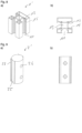
- Figur 4
- die Darstellung des Einsatzes der Vorrichtung aus
Figur 2 - a) in räumlicher Darstellung;
- b) in der Draufsicht;
- Figur 5
- die räumliche Darstellung des Anschlagstücks der Vorrichtung aus
Figur 2 ; - Figur 6
- die räumliche Darstellung des Druckstücks der Vorrichtung aus
Figur 2 ; - Figur 7
- die Darstellung des Abdeckprofils der Vorrichtung aus
Figur 2 - a) in räumlicher Darstellung;
- b) in der Draufsicht;
- Figur 8
- die Darstellung eines Zaunpfahlprofils in einer weiteren Ausführungsform
- a) in räumlicher Darstellung;
- b) in der Draufsicht;
- Figur 9
- die Darstellung eines Scharniereinsatzes
- a) in räumlicher Darstellung;
- b) in der Draufsicht.
- Der als Ausführungsbeispiel gewählte, mit einer erfindungsgemäßen Vorrichtung zur Aufnahme von Flächenelementen montierte Zaunabschnitt umfasst ein Zaunpfahlprofil 1, das mit Längsnuten 11 versehen ist, in denen Einsätze 2 schwenkbar angeordnet sind, die zwischen einem Anschlagstück 3 und einem Druckstück 4 axial gehalten sind und die eine zweite Längsnut 21 zur Aufnahme eines Flächenelements 8 aufweist. Das Zaunpfahlprofil 1 ist an einer Stirnseite über eine Deckplatte 5 verschlossen, auf die eine Haube 6 aufgebracht ist. In die Einsätze 2 einer ersten Längsnut 11 des Zaunpfahlprofils 1 ist jeweils ein als Paneele ausgeführtes Flächenelement 8 eingesetzt, wodurch eine geschlossene Zaunfläche gebildet ist. Das Zaunpfahlprofil 1 ist über einen Bodenanker 9 befestigt, der in dieses hineinragt. In
Figur 2 ist die Vorrichtung vereinfacht mit verkürztem Zaunpfahlprofil 1 dargestellt, in dessen Längsnuten 11 jeweils nur ein Einsatz 2 eingebracht ist. - Das Zaunpfahlprofil 1 ist im Ausführungsbeispiel als Aluminiumstrangpresshohlprofil mit im Wesentlichen quadratischem Querschnitt ausgebildet. An drei Längsseiten weist das Zaunpfahlprofil 1 mittig jeweils eine erste Längsnut 11 auf, die sich über dessen gesamte Länge erstreckt und einen kreisbogenförmigen Querschnitt aufweist, der einen Winkel von 240° umspannt, wodurch beidseitig dessen Längsöffnung ein Hinterschnitt 111 gebildet ist. Die vierte Seite ist geschlossen ausgeführt. In die ersten Längsnuten sind jeweils gegenüberliegend zwei axiale Rastnuten 12 eingebracht, die sich über die gesamte Länge der ersten Längsnuten 11 erstrecken. Die Längsnuten 11 begrenzen einen Mittelkanal 13, der einen quadratischen Querschnitt aufweist und der sich entlang der Mittelachse des Zaunpfahlprofils 1 erstreckt.
- Der Einsatz 2 ist zylinderförmig ausgebildet und im Ausführungsbeispiel als Kunststoffspritzgussteil hergestellt. In die Außenmantelfläche des Einsatzes 2 ist eine zweite Längsnut 21 eingebracht, die sich über die gesamte Länge des Einsatzes 2 erstreckt. Die zweite Längsnut 21 geht radial in einen verbreiterten Abschnitt 22 mit rechteckigem Querschnitt über, wodurch die Innenkontur eines C-Profils gebildet ist. Bedingt durch die zweite Längsnut 21 weist der Einsatz 2 einen bogenförmigen Querschnitt auf, der einen Winkel von 220° umspannt. In die drei Seitenwände des verbreiterten Abschnitts 22 der zweiten Längsnut 21 ist jeweils eine Aufnahme 23 für ein Dichtungselement 24 eingebracht. Die Aufnahme 23 umfasst eine Längsnut 231, von deren Grund ein Einschnitt 232 ausgeht, wodurch ein Hinterschnitt gebildet ist.
- Das Anschlagstück 3 ist zylindersegmentförmig ausgebildet und weist eine Außenmantelfläche auf, die mit der Innenmantelfläche der ersten Längsnut 11 des Zaunpfahlprofils 1 korrespondiert, in die es einsetzbar ist. Durch seine zylindersegmentförmige Ausbildung kann das Anschlagstück 3 von vorne in eine orthogonal zur Längsachse des Zaunpfahlprofils 1 gerichtete Richtung in einer Schwenkstellung in die erste Längsnut 11 eingesetzt werden, wo es nach Verschwenken um seine Längsachse an dem Hinterschnitt 111 anliegt und so radial fixiert ist. Zur axialen Fixierung des Anschlagstücks 3 in der ersten Längsnut 11 ist eine radiale Gewindebohrung 31 angeordnet, in die eine - nicht dargestellte - Madenschraube - eingeschraubt ist, die gegen das Zaunpfahlprofil 1 verspannbar ist. Die Gewindebohrung 31 ist durch einen Abdeckpfropfen 32 verschließbar.
- Das Druckstück 4 umfasst einen im Wesentlichen zylindrischen Druckkörper 41, der zentrisch mit einer Gewindestange 42 versehen ist, mit der er in eine in der Deckplatte 5 hierzu vorgesehene Gewindebohrung 51 eingeschraubt ist. Der Außendurchmesser des Druckkörpers 41 ist kleiner als der Innendurchmesser der ersten Längsnut 11 des Zaunpfahlprofils 1. Die Gewindestange 42 ist drehbar, jedoch axial fixiert in dem Druckkörper 41 gelagert. Kopfseitig ist in die Gewindestange 42 ein - nicht dargestellter - Schlitz zum Eingriff eines Schraubendrehers eingebracht. Durch Drehung der Gewindestange 42 in der Gewindebohrung 51 ist der Druckkörper 41 axial in der ersten Längsnut 11 des Zaunpfahlprofils 1 bewegbar. Im Ausführungsbeispiel ist der Druckkörper 41 aus Kunststoff, vorzugsweise aus einem Elastomerkunststoff hergestellt.
- Die Deckplatte 5 ist im Wesentlichen quadratisch ausgebildet und weißt eine Außenkontur auf, die Außenkontur des Querschnitts des Zaunpfahlprofils 1 entspricht. In die Deckplatte sind vier Bohrungen 52 eingebracht, durch die - nicht dargestellte - Schrauben geführt sind, die in vier hierzu in dem Zaunpfahlprofil 1 kopfseitig angeordnete Gewindebohrungen 14 eingeschraubt sind.
- Die Haube 6 ist in Form eines quadratischen Prismas ausgebildet, an das sich ein umlaufender Kragen 61 anschließt. Die Innenkontur des Kragens 61 entspricht im Wesentlichen der Außenkontur des Querschnitts des Zaunpfahlprofils 1, das der Kragen 61 in aufgestülpter Position der Haube 6 umfasst. Im Ausführungsbeispiel ist die Haube 6 aus Aluminium hergestellt.
- Das Abdeckprofil 7 ist im Ausführungsbeispiel einstückig ausgebildet und umfasst eine rechteckige Grundplatte 71, an deren Längsseiten zwei gegenüberliegend positionierte, nach innen geneigte Seitenwände 72 angeordnet sind, die an ihrem freien Ende jeweils mit einer nach außen kragenden Rastleiste 73 versehen sind. Parallel zu der Grundplatte 71 ist zwischen den Seitenwänden 72 ein der Grundplatte 71 entgegengerichtet gewölbtes Spannelement 74 angeordnet.
- Der Bodenanker 9 besteht im Wesentlichen aus einer Befestigungsplatte 91, auf der mittig ein Steckprofil 92 angeordnet ist. Die Außenkontur des Steckprofils 92 entspricht im Wesentlichen der Innenkontur des Mittelkanals 13 des Zaunpfahlprofils 1, in das dieses hineinragt.
- Zur Erstellung eines Zaunabschnitts wird zunächst bodenseitig ein Anschlagstück 3 in eine erste Längsnut 11 eines Zaunpfahlprofils 1 eingebracht, das auf dem Steckprofil 92 eines Bodenankers 9 befestigt ist. Nachfolgend werden Einsätze 2 auf das Anschlagstück 3 aufgestapelt in die erste Längsnut 11 eingeschwenkt. In die zweite Längsnut 21 der Einsätze 2 werden nachfolgend Flächenelemente 8 eingeschoben, die zwischen den Dichtungselementen 24 eingespannt gehalten sind. Die gewünschte Ausrichtung der Flächenelemente 8 kann nun durch Verschwenken über die in dem Zaunpfahlprofil 1 schwenkbar gelagerten Einsätze 2 erfolgen. Mit ihrem freien Ende werden die Flächenelemente 8 entsprechend in Einsätze 2 eines weiteren Zaunpfahlprofils 1 eingesteckt, die dort wiederum zwischen den Dichtungselementen 24 eingespannt gehalten sind.
- Auf das Zaunpfahlprofil 1 wird eine mit erforderlichen Druckstücken 4 versehene Deckplatte 5 über durch deren Bohrungen 52 geführte Schrauben befestigt, die in hierfür vorgesehene Gewindebohrungen 14 des Zaunpfahlprofils 1 eingeschraubt werden. Die in der ersten Längsnut 1 des jeweiligen Zaunpfahlprofils 1 eingebrachten Einsätze 2 mit in diesen gehaltenen Flächenelementen 8 werden über den in die erste Längsnut hineinragenden Druckkörper 41 des Druckstücks 4 durch Drehung der Gewindestange 42 in der Gewindebohrung 51 der Deckplatte 5 axial gegen das Anschlagstück 3 verspannt.
- Nicht verwendete erste Längsnuten 1 werden über ein Abdeckprofil 7 verschlossen, das hierzu mit seinen Seitenwänden 72 in die jeweilige erste Längsnut 1 eingedrückt wird, bis deren Rastleisten 73 in die Rastnuten 12 der ersten Längsnut 1 einrasten. Die Rastleisten 73 sind durch das Spannelement 74 gegen die Rastnuten 12 verspannt. Zuletzt wird die Haube 6 mit ihrem Kragen 61 auf das Zaunpfahlprofil 1 aufgestülpt.
- Im Ausführungsbeispiel gemäß den
Figuren 8 und 9 sind zur optionalen Befestigung eines - nicht dargestellten - Scharniers eines Tores in der ersten Längsnut 1 des Zaunpfostenprofils 1' zusätzlich gegenüberliegend positionierte Haltenuten zur Fixierung eines Scharniereinsatzes 2' angeordnet. Der Scharniereinsatz 2' ist hierzu als Vollzylinder ausgebildet und zur weiteren Verankerung mit gegenüberliegend angeordneten Halteleisten 25 zum Eingriff in die Haltenuten 15 der ersten Längsnut 11 des Zaunpfostenprofils 1' versehen. Beabstandet zu den Halteleisten 25 sind weiterhin zwei Rastleisten 27 zum Verrastung mit der Rastnut 12 der ersten Längsnut 11 angeordnet. Zur Befestigung eines Scharniers ist der Scharniereinsatz 2' mit zwei beabstandet zueinander angeordneten, radialen Gewindebohrungen 26 versehen. Der Scharniereinsatz kann zwischen zwei hierzu in der ersten Längsnut 1 eingebrachten Anschlagstücken 3 fixiert werden. Je nach erforderlicher Anzahl an Torscharnieren können zwei oder mehr Scharniereinsätze 2' in der Längsnut 1 angeordnet werden. Zwischen den Scharniereinsätzen kann ein entsprechend gekürztes Abdeckprofil 7 in die erste Längsnut 1 eingebracht werden.
Claims (14)
- Vorrichtung zur Aufnahme von Flächenelementen (8) zur Herstellung eines Zauns, umfassend ein Zaunpfahlprofil (1, 1'), das an wenigstens einer Seite eine sich über seine Länge erstreckende erste Längsnut (11) aufweist, deren Längsöffnung verjüngt ist, wodurch ein Hinterschnitt (111) gebildet ist, wobei, dass wenigstens eine erste Längsnut (11) einen Einsatz (2) aufnimmt, der eine zweite Längsnut (21) zur Aufnahme eines Flächenelements (8) aufweist und der in der ersten Längsnut (11) um seine Längsachse schwenkbar ist, wobei in wenigstens einer ersten Längsnut (11) ein Anschlagstück (3) angeordnet ist, das stufenlos längsverschiebbar ist, dadurch gekennzeichnet, dass das Anschlagstück (3) über ein Spannmittel in einer Längsposition fixierbar ist.
- Vorrichtung nach Anspruch 1, dadurch gekennzeichnet, dass die erste Längsnut (11) einen kreisbogenförmigen Querschnitt aufweist, dessen Kreisbogen einen Winkel von größer 200° umspannt, wobei der Einsatz (2) zylinderförmig ausgebildet ist.
- Vorrichtung nach Anspruch 2, dadurch gekennzeichnet, dass der Einsatz (2) bedingt durch die zweite Längsnut (21) einen kreisbogenförmigen Querschnitt aufweist, der einen Winkel von größer 200°, bevorzugt von größer 240° umspannt und derart ausgebildet ist, dass er von vorne in eine orthogonal zur Längsachse des Zaunpfahlprofils (1) gerichtete Richtung in einer Schwenkstellung in die erste Längsnut (11) einsetzbar ist, wo er nach Verschwenken um seine Längsachse radial fixiert ist.
- Vorrichtung nach einem der vorgenannten Ansprüche, dadurch gekennzeichnet, dass die zweite Längsnut (21) einen im Wesentlichen C-förmigen Querschnitt aufweist.
- Vorrichtung nach einem der vorgenannten Ansprüche, dadurch gekennzeichnet, dass zumindest an zwei gegenüberliegenden Seitenwänden der zweiten Längsnut (21) zumindest bereichsweise ein elastisches Dichtungselement (24) angeordnet ist.
- Vorrichtung nach Anspruch 5, dadurch gekennzeichnet, dass das elastische Dichtungselement (24) in eine in der Seitenwand angeordnete Aufnahme (23) eingesetzt ist oder an die Seitenwand angespritzt oder angeklebt ist.
- Vorrichtung nach einem der vorgenannten Ansprüche, dadurch gekennzeichnet, dass in die Seitenwände zumindest einer ersten Längsnut (11) des Zaunpfahlprofils (1) gegenüberliegend Rastnuten (12) eingebracht sind, wobei ein Abdeckprofil (7) vorgesehen ist, das zum Verschließen der Längsnut über Rastleisten (73) in die Rastnuten (12) der ersten Längsnut (11) des Zaunpfahlprofils (1) einrastbar ist.
- Vorrichtung nach einem der vorgenannten Ansprüche, dadurch gekennzeichnet, dass das Zaunpfahlprofil (1) im Wesentlichen quaderförmig ausgebildet ist und vorzugsweise aus Metall, insbesondere aus Aluminium hergestellt ist.
- Vorrichtung nach einem der vorgenannten Ansprüche, dadurch gekennzeichnet, dass das Spannmittel eine Spannschraube ist.
- Vorrichtung nach Anspruch 9, dadurch gekennzeichnet, dass das Anschlagstück (3) den Querschnitt der Längsnut im Wesentlichen ausfüllt.
- Vorrichtung nach einem der vorgenannten Ansprüche, dadurch gekennzeichnet, dass das Zaunpfahlprofil (1) an einer Kopfseite über eine, die vorhandenen ersten Längsnuten (11) axial verschließend angeordnete Deckplatte (5) verschlossen ist.
- Vorrichtung nach Anspruch 11, dadurch gekennzeichnet, dass in wenigstens einer ersten Längsnut (11) ein vorzugsweise elastisches Druckstück (4) angeordnet ist, das über ein Spannmittel, vorzugsweise eine Gewindestange (42) mit der Deckplatte (5) verbunden ist.
- Vorrichtung nach einem der vorgenannten Ansprüche, dadurch gekennzeichnet, dass das Zaunpfahlprofil (1) entlang seiner Mittellängsachse einen Mittelkanal (13) aufweist.
- Vorrichtung nach Anspruch 13, dadurch gekennzeichnet, dass ein Bodenanker (9) vorgesehen ist, mit einem Steckprofil (92), das zur Befestigung des Zaunpfahlprofils (1) in den Mittelkanal (13) einsteckbar ist, wobei dessen Außenkontur im Wesentlichen der Innenkontur des Mittelkanals (13) entspricht.
Priority Applications (1)
| Application Number | Priority Date | Filing Date | Title |
|---|---|---|---|
| EP22165145.8A EP4253696B1 (de) | 2022-03-29 | 2022-03-29 | Vorrichtung zur aufnahme von flächenelementen |
Applications Claiming Priority (1)
| Application Number | Priority Date | Filing Date | Title |
|---|---|---|---|
| EP22165145.8A EP4253696B1 (de) | 2022-03-29 | 2022-03-29 | Vorrichtung zur aufnahme von flächenelementen |
Publications (3)
| Publication Number | Publication Date |
|---|---|
| EP4253696A1 EP4253696A1 (de) | 2023-10-04 |
| EP4253696C0 EP4253696C0 (de) | 2025-04-23 |
| EP4253696B1 true EP4253696B1 (de) | 2025-04-23 |
Family
ID=80999513
Family Applications (1)
| Application Number | Title | Priority Date | Filing Date |
|---|---|---|---|
| EP22165145.8A Active EP4253696B1 (de) | 2022-03-29 | 2022-03-29 | Vorrichtung zur aufnahme von flächenelementen |
Country Status (1)
| Country | Link |
|---|---|
| EP (1) | EP4253696B1 (de) |
Family Cites Families (5)
| Publication number | Priority date | Publication date | Assignee | Title |
|---|---|---|---|---|
| GB1404982A (en) * | 1972-01-13 | 1975-09-03 | Baloglaze Ltd | Balustrades and railway sturctures |
| DE202005003011U1 (de) * | 2005-01-20 | 2005-05-12 | Brix Zaun + Tor Gmbh | Steher zum Einrichten von Zäunen und Geländern |
| FR3032003B1 (fr) * | 2015-01-22 | 2017-01-13 | Men 85 | Poteau pour la realisation de fermeture tel que cloture, portail, porte ou similaire, ensemble et fermeture comprenant un tel poteau |
| DE202016106503U1 (de) | 2016-11-21 | 2016-12-02 | Valu Gmbh | Nutstein und Zaunsystem |
| KR101910532B1 (ko) * | 2018-05-18 | 2018-10-22 | 이성재 | 펜스 조립체 |
-
2022
- 2022-03-29 EP EP22165145.8A patent/EP4253696B1/de active Active
Also Published As
| Publication number | Publication date |
|---|---|
| EP4253696A1 (de) | 2023-10-04 |
| EP4253696C0 (de) | 2025-04-23 |
Similar Documents
| Publication | Publication Date | Title |
|---|---|---|
| DE102005057397A1 (de) | Mehrzweckprofile für den Zusammenbau von Rahmen, Haltevorrichtungen, tragenden Teilen und ähnlichem | |
| EP3835638A1 (de) | Vorrichtung zur befestigung von leitungen | |
| DE19641500C2 (de) | Vorrichtung zum lösbaren Verbinden von Profilstäben | |
| DE102017127119A1 (de) | Vorrichtung zum Positionieren eines Fensters oder einer Tür | |
| EP4253696B1 (de) | Vorrichtung zur aufnahme von flächenelementen | |
| DE102018122142B4 (de) | Klemmaufnahme und Bandtasche | |
| DE102014102793A1 (de) | Befestigungselement für einen Stromsensor | |
| EP0442367A2 (de) | Vorrichtung zum Verschliessen einer KabeldurchfÀ¼hrungsöffnung in einem Schaltschrank | |
| DE29703227U1 (de) | Schnellmontagetopf für Möbelscharniere | |
| EP3290622A1 (de) | Vorrichtung zum ausgleich von längendifferenzen zwischen einem zylinderschloss und einem türblatt | |
| EP1666688B1 (de) | Band für Fenster, Türen und dergleichen | |
| DE10315045A1 (de) | Verbindung von zwei Profilstäben und Absperrungskonstruktion mit derartigen Verbindungen | |
| CH719561B1 (de) | Vorrichtung zur Aufnahme von Flächenelementen zur Herstellung eines Zauns. | |
| DE202022101663U1 (de) | Vorrichtung zur Aufnahme von Flächenelementen | |
| AT17917U1 (de) | Vorrichtung zur Aufnahme von Flächenelementen | |
| EP3078785B1 (de) | Befestigungsvorrichtung | |
| EP3074649B1 (de) | Abstandshalter für eine gleitführung und hubsäule | |
| DE102018101285A1 (de) | Eckverbinder | |
| DE3706236C2 (de) | Verbindungselement für zwei Tragteile | |
| EP3535468B1 (de) | Dämpfungselement und türbeschlag für eine falt- oder schiebetür | |
| DE29805705U1 (de) | Hammerkopfschraube | |
| EP2088335B1 (de) | Profilverbinder | |
| DE3540848A1 (de) | Einsteckschloss mit variablem dornmass | |
| EP1126110B1 (de) | Schliessvorrichtung für Türen und Fenster | |
| DE102005044127B4 (de) | Trägerteil für einen Sammelschienenträger sowie Sammelschienenträger |
Legal Events
| Date | Code | Title | Description |
|---|---|---|---|
| PUAI | Public reference made under article 153(3) epc to a published international application that has entered the european phase |
Free format text: ORIGINAL CODE: 0009012 |
|
| STAA | Information on the status of an ep patent application or granted ep patent |
Free format text: STATUS: REQUEST FOR EXAMINATION WAS MADE |
|
| 17P | Request for examination filed |
Effective date: 20221209 |
|
| AK | Designated contracting states |
Kind code of ref document: A1 Designated state(s): AL AT BE BG CH CY CZ DE DK EE ES FI FR GB GR HR HU IE IS IT LI LT LU LV MC MK MT NL NO PL PT RO RS SE SI SK SM TR |
|
| GRAP | Despatch of communication of intention to grant a patent |
Free format text: ORIGINAL CODE: EPIDOSNIGR1 |
|
| STAA | Information on the status of an ep patent application or granted ep patent |
Free format text: STATUS: GRANT OF PATENT IS INTENDED |
|
| INTG | Intention to grant announced |
Effective date: 20240709 |
|
| GRAS | Grant fee paid |
Free format text: ORIGINAL CODE: EPIDOSNIGR3 |
|
| GRAJ | Information related to disapproval of communication of intention to grant by the applicant or resumption of examination proceedings by the epo deleted |
Free format text: ORIGINAL CODE: EPIDOSDIGR1 |
|
| GRAL | Information related to payment of fee for publishing/printing deleted |
Free format text: ORIGINAL CODE: EPIDOSDIGR3 |
|
| STAA | Information on the status of an ep patent application or granted ep patent |
Free format text: STATUS: REQUEST FOR EXAMINATION WAS MADE |
|
| INTC | Intention to grant announced (deleted) | ||
| GRAP | Despatch of communication of intention to grant a patent |
Free format text: ORIGINAL CODE: EPIDOSNIGR1 |
|
| STAA | Information on the status of an ep patent application or granted ep patent |
Free format text: STATUS: GRANT OF PATENT IS INTENDED |
|
| INTG | Intention to grant announced |
Effective date: 20250127 |
|
| GRAA | (expected) grant |
Free format text: ORIGINAL CODE: 0009210 |
|
| STAA | Information on the status of an ep patent application or granted ep patent |
Free format text: STATUS: THE PATENT HAS BEEN GRANTED |
|
| AK | Designated contracting states |
Kind code of ref document: B1 Designated state(s): AL AT BE BG CH CY CZ DE DK EE ES FI FR GB GR HR HU IE IS IT LI LT LU LV MC MK MT NL NO PL PT RO RS SE SI SK SM TR |
|
| REG | Reference to a national code |
Ref country code: GB Ref legal event code: FG4D Free format text: NOT ENGLISH |
|
| REG | Reference to a national code |
Ref country code: CH Ref legal event code: EP |
|
| REG | Reference to a national code |
Ref country code: DE Ref legal event code: R096 Ref document number: 502022003631 Country of ref document: DE |
|
| REG | Reference to a national code |
Ref country code: IE Ref legal event code: FG4D Free format text: LANGUAGE OF EP DOCUMENT: GERMAN |
|
| U01 | Request for unitary effect filed |
Effective date: 20250523 |
|
| U07 | Unitary effect registered |
Designated state(s): AT BE BG DE DK EE FI FR IT LT LU LV MT NL PT RO SE SI Effective date: 20250602 |
|
| PG25 | Lapsed in a contracting state [announced via postgrant information from national office to epo] |
Ref country code: ES Free format text: LAPSE BECAUSE OF FAILURE TO SUBMIT A TRANSLATION OF THE DESCRIPTION OR TO PAY THE FEE WITHIN THE PRESCRIBED TIME-LIMIT Effective date: 20250423 |
|
| PG25 | Lapsed in a contracting state [announced via postgrant information from national office to epo] |
Ref country code: NO Free format text: LAPSE BECAUSE OF FAILURE TO SUBMIT A TRANSLATION OF THE DESCRIPTION OR TO PAY THE FEE WITHIN THE PRESCRIBED TIME-LIMIT Effective date: 20250723 Ref country code: GR Free format text: LAPSE BECAUSE OF FAILURE TO SUBMIT A TRANSLATION OF THE DESCRIPTION OR TO PAY THE FEE WITHIN THE PRESCRIBED TIME-LIMIT Effective date: 20250724 |
|
| PG25 | Lapsed in a contracting state [announced via postgrant information from national office to epo] |
Ref country code: PL Free format text: LAPSE BECAUSE OF FAILURE TO SUBMIT A TRANSLATION OF THE DESCRIPTION OR TO PAY THE FEE WITHIN THE PRESCRIBED TIME-LIMIT Effective date: 20250423 |
|
| PG25 | Lapsed in a contracting state [announced via postgrant information from national office to epo] |
Ref country code: HR Free format text: LAPSE BECAUSE OF FAILURE TO SUBMIT A TRANSLATION OF THE DESCRIPTION OR TO PAY THE FEE WITHIN THE PRESCRIBED TIME-LIMIT Effective date: 20250423 |
|
| PG25 | Lapsed in a contracting state [announced via postgrant information from national office to epo] |
Ref country code: RS Free format text: LAPSE BECAUSE OF FAILURE TO SUBMIT A TRANSLATION OF THE DESCRIPTION OR TO PAY THE FEE WITHIN THE PRESCRIBED TIME-LIMIT Effective date: 20250723 |
|
| PG25 | Lapsed in a contracting state [announced via postgrant information from national office to epo] |
Ref country code: IS Free format text: LAPSE BECAUSE OF FAILURE TO SUBMIT A TRANSLATION OF THE DESCRIPTION OR TO PAY THE FEE WITHIN THE PRESCRIBED TIME-LIMIT Effective date: 20250823 |
|
| PG25 | Lapsed in a contracting state [announced via postgrant information from national office to epo] |
Ref country code: SM Free format text: LAPSE BECAUSE OF FAILURE TO SUBMIT A TRANSLATION OF THE DESCRIPTION OR TO PAY THE FEE WITHIN THE PRESCRIBED TIME-LIMIT Effective date: 20250423 |
|
| PG25 | Lapsed in a contracting state [announced via postgrant information from national office to epo] |
Ref country code: CZ Free format text: LAPSE BECAUSE OF FAILURE TO SUBMIT A TRANSLATION OF THE DESCRIPTION OR TO PAY THE FEE WITHIN THE PRESCRIBED TIME-LIMIT Effective date: 20250423 |
|
| PG25 | Lapsed in a contracting state [announced via postgrant information from national office to epo] |
Ref country code: SK Free format text: LAPSE BECAUSE OF FAILURE TO SUBMIT A TRANSLATION OF THE DESCRIPTION OR TO PAY THE FEE WITHIN THE PRESCRIBED TIME-LIMIT Effective date: 20250423 |
|
| PLBE | No opposition filed within time limit |
Free format text: ORIGINAL CODE: 0009261 |
|
| STAA | Information on the status of an ep patent application or granted ep patent |
Free format text: STATUS: NO OPPOSITION FILED WITHIN TIME LIMIT |
|
| REG | Reference to a national code |
Ref country code: CH Ref legal event code: L10 Free format text: ST27 STATUS EVENT CODE: U-0-0-L10-L00 (AS PROVIDED BY THE NATIONAL OFFICE) Effective date: 20260304 |
|
| 26N | No opposition filed |
Effective date: 20260126 |
|
| U20 | Renewal fee for the european patent with unitary effect paid |
Year of fee payment: 5 Effective date: 20260313 |