EP4253659A1 - A block for a vegetation wall - Google Patents
A block for a vegetation wall Download PDFInfo
- Publication number
- EP4253659A1 EP4253659A1 EP22305412.3A EP22305412A EP4253659A1 EP 4253659 A1 EP4253659 A1 EP 4253659A1 EP 22305412 A EP22305412 A EP 22305412A EP 4253659 A1 EP4253659 A1 EP 4253659A1
- Authority
- EP
- European Patent Office
- Prior art keywords
- block
- wall
- opening
- sidewall
- back wall
- Prior art date
- Legal status (The legal status is an assumption and is not a legal conclusion. Google has not performed a legal analysis and makes no representation as to the accuracy of the status listed.)
- Granted
Links
Images
Classifications
-
- E—FIXED CONSTRUCTIONS
- E01—CONSTRUCTION OF ROADS, RAILWAYS, OR BRIDGES
- E01F—ADDITIONAL WORK, SUCH AS EQUIPPING ROADS OR THE CONSTRUCTION OF PLATFORMS, HELICOPTER LANDING STAGES, SIGNS, SNOW FENCES, OR THE LIKE
- E01F8/00—Arrangements for absorbing or reflecting air-transmitted noise from road or railway traffic
- E01F8/02—Arrangements for absorbing or reflecting air-transmitted noise from road or railway traffic specially adapted for sustaining vegetation or for accommodating plants ; Embankment-type or crib-type noise barriers; Retaining walls specially adapted to absorb or reflect noise
- E01F8/021—Arrangements for absorbing or reflecting air-transmitted noise from road or railway traffic specially adapted for sustaining vegetation or for accommodating plants ; Embankment-type or crib-type noise barriers; Retaining walls specially adapted to absorb or reflect noise with integral support structure
- E01F8/023—Arrangements for absorbing or reflecting air-transmitted noise from road or railway traffic specially adapted for sustaining vegetation or for accommodating plants ; Embankment-type or crib-type noise barriers; Retaining walls specially adapted to absorb or reflect noise with integral support structure made of stacked or staggered elements, e.g. hollow
-
- A—HUMAN NECESSITIES
- A01—AGRICULTURE; FORESTRY; ANIMAL HUSBANDRY; HUNTING; TRAPPING; FISHING
- A01G—HORTICULTURE; CULTIVATION OF VEGETABLES, FLOWERS, RICE, FRUIT, VINES, HOPS OR SEAWEED; FORESTRY; WATERING
- A01G9/00—Cultivation in receptacles, forcing-frames or greenhouses; Edging for beds, lawn or the like
- A01G9/02—Receptacles, e.g. flower-pots or boxes; Glasses for cultivating flowers
- A01G9/022—Pots for vertical horticulture
- A01G9/025—Containers and elements for greening walls
-
- E—FIXED CONSTRUCTIONS
- E04—BUILDING
- E04C—STRUCTURAL ELEMENTS; BUILDING MATERIALS
- E04C1/00—Building elements of block or other shape for the construction of parts of buildings
- E04C1/39—Building elements of block or other shape for the construction of parts of buildings characterised by special adaptations, e.g. serving for locating conduits, for forming soffits, cornices, or shelves, for fixing wall-plates or door-frames, for claustra
- E04C1/395—Building elements of block or other shape for the construction of parts of buildings characterised by special adaptations, e.g. serving for locating conduits, for forming soffits, cornices, or shelves, for fixing wall-plates or door-frames, for claustra for claustra, fences, planting walls, e.g. sound-absorbing
-
- E—FIXED CONSTRUCTIONS
- E04—BUILDING
- E04B—GENERAL BUILDING CONSTRUCTIONS; WALLS, e.g. PARTITIONS; ROOFS; FLOORS; CEILINGS; INSULATION OR OTHER PROTECTION OF BUILDINGS
- E04B2/00—Walls, e.g. partitions, for buildings; Wall construction with regard to insulation; Connections specially adapted to walls
- E04B2/02—Walls, e.g. partitions, for buildings; Wall construction with regard to insulation; Connections specially adapted to walls built-up from layers of building elements
- E04B2/42—Walls having cavities between, as well as in, the elements; Walls of elements each consisting of two or more parts, kept in distance by means of spacers, at least one of the parts having cavities
- E04B2/50—Walls having cavities between, as well as in, the elements; Walls of elements each consisting of two or more parts, kept in distance by means of spacers, at least one of the parts having cavities using elements having a general shape differing from that of a parallelepiped
-
- Y—GENERAL TAGGING OF NEW TECHNOLOGICAL DEVELOPMENTS; GENERAL TAGGING OF CROSS-SECTIONAL TECHNOLOGIES SPANNING OVER SEVERAL SECTIONS OF THE IPC; TECHNICAL SUBJECTS COVERED BY FORMER USPC CROSS-REFERENCE ART COLLECTIONS [XRACs] AND DIGESTS
- Y02—TECHNOLOGIES OR APPLICATIONS FOR MITIGATION OR ADAPTATION AGAINST CLIMATE CHANGE
- Y02P—CLIMATE CHANGE MITIGATION TECHNOLOGIES IN THE PRODUCTION OR PROCESSING OF GOODS
- Y02P60/00—Technologies relating to agriculture, livestock or agroalimentary industries
- Y02P60/20—Reduction of greenhouse gas [GHG] emissions in agriculture, e.g. CO2
Definitions
- the present disclosure relates generally to a block for constructing a vegetation wall and to the vegetation wall constructed therefrom.
- Heat islands are urbanized areas that experience higher temperatures than outlying areas. Structures such as buildings, roads, and other infrastructure absorb and re-emit the sun's heat more than natural landscapes such as forests and water bodies.
- Rendering construction elements such as buildings, green is a practice that is becoming increasingly widespread and increasingly sought after to reduce the heat island effect.
- rendering construction elements green is a sought-after practice for aesthetic, thermal or phonic insulation and air or water quality reasons.
- the covering of surfaces with vegetation thus makes a real contribution to the quality of life of inhabitants of urban areas.
- existing green wall structures are considered luxury items due to the significant costs of maintaining the wall and the vegetation disposed therein.
- the cost per square meter of green wall structures can amount to several hundred euros per year.
- One maintenance feature is watering of the vegetation of the wall.
- Existing green wall structures often require the integration of complex irrigation systems therein to support and grow the vegetation.
- One objective of the present disclosure is to provide a block used for construction of a vegetation wall.
- each block is configured such that, when a plurality of blocks are assembled together, a watering system is integrally formed therewith. Accordingly, the cost of construction and maintenance of the wall is reduced relative to the vegetation walls requiring separately integrating irrigation or watering systems.
- the invention proposes a block for supporting vegetation growth comprising a back wall, a front wall, a first sidewall extending between and connecting the back wall and the front wall, and a second sidewall extending between and connecting the back wall and the front wall.
- the block further comprises a first inner wall extending from the back wall to the first sidewall.
- the first inner wall, the back wall, and the first sidewall collectively define a first opening.
- the first inner wall intersects the back wall at a lateral distance measured from a first side surface of the back wall that is greater than about 33% and less than about 45% of the length of the back wall.
- the first inner wall intersects the first sidewall at a lateral distance measured from a rear surface of the back wall that is greater than about 50% and less than or equal to about 65% of a depth of the block.
- the block further comprises a second inner wall extending from the back wall to the second sidewall.
- the second inner wall, the back wall, and the second sidewall collectively defining a second opening.
- the second inner wall intersects the back wall at a lateral distance measured from a second side surface of the back wall that is greater than about 33% and less than about 45% of the length of the back wall.
- the second inner wall intersects the second sidewall at a lateral distance measured from the rear surface of the back wall that is greater than about 50% and less than or equal to about 65% of the depth of the block.
- the back wall, the front wall, the first sidewall, the second sidewall, the first inner wall, and the second sidewall collectively define a third opening.
- Another objective of the present disclosure is to provide a wall comprising a plurality of the blocks described above.
- the plurality of blocks comprising a first block and a second block in a first row and a third block in a second row, and the first row is located vertically adjacent to the second row.
- the first block, the second block, and the third block are arranged such that the first block and the second block are disposed over an upper surface of the third block.
- the first block and the second block are disposed against each other on a side surface of the respective back walls thereof and meet intermediately along a length of the back wall of the third block.
- the second opening of the first block overlaps with the first opening of the third block and the first opening of the second block overlaps with the second opening of the third block.
- the respectively overlapping first and second openings collectively form a channel. Each channel extends vertically through the first and second rows such that water is able to flow to each row.
- spatially relative terms such as “below,” “lower,” “above,” “over,” “upper,” “top,” “front,” “rear,” “left,” “right,” and the like, may be used for ease of description to describe one element's or feature's relationship to another element(s) or feature(s) as illustrated in the figures. Unless otherwise specified, the spatially relative terms are intended to encompass different orientations of the devices in addition to the orientation depicted in the figures. For example, if devices in the figures are inverted, elements described as “upper” or “on” other elements or features would then be oriented “lower” or “under” the other elements or features.
- the term "substantially" in reference to a given parameter, property, or condition means and includes to a degree that one of ordinary skill in the art would understand that the given parameter, property, or condition is met with a degree of variance, such as within acceptable manufacturing tolerances.
- the term "about” in reference to a given parameter is inclusive of the stated value and has the meaning dictated by the context (e.g., it includes the degree of error associated with measurement of the given parameter).
- the terms “comprising,” “including,” “containing,” and grammatical equivalents thereof are inclusive or open-ended terms that do not exclude additional, unrecited elements or method steps, but also include the more restrictive terms “consisting of' and “consisting essentially of' and grammatical equivalents thereof.
- the term “configured” refers to a size, shape, orientation, and arrangement of at least one structure and at least one apparatus facilitating operation of the structure or the apparatus in a pre-determined way.
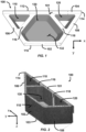
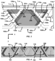
- FIGS. 1-3 illustrate a block 100 according to embodiments of the present disclosure.
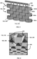
- FIGS. 4-6 illustrate a wall 200 favorable to the growth of vegetation formed from a plurality of the blocks 100 as will be explained in further detail below.
- the block 100 is a unitary structure defining a plurality of openings.
- unitary structure means a structure formed as a single piece or single unit.
- the block 100 comprises a front wall 102, a back wall 104, a first sidewall 106, and a second sidewall 108.
- the first and second sidewalls 106, 108 extend between and connect the front wall 102 and the back wall 104.
- the front wall 102, the back wall 104, the first sidewall 106, and the second sidewall 108 define a perimeter of the block 100.
- FIGS. 1 and 2 A coordinate system is illustrated in FIGS. 1 and 2 .
- the terms “axial,” “axially,” “vertical,” “vertically,” “longitudinal,” and “longitudinally” generally mean and refer to a direction along or parallel to the z-direction in the coordinate system.
- the vertical direction is a direction extending from an upper surface 101 to a lower surface 103 of the block 100 described herein.
- the term “height” refers to a dimension measured in the z-direction.
- the terms “horizontal,” “horizontally,” “lateral” and “laterally” generally means and refers to a direction along or parallel to either the x-direction or y-direction.
- the lateral direction is a direction parallel to a plane in which the upper surface 101 of the block 100 lies.
- the lateral direction is perpendicular to the vertical or longitudinal direction.
- a rear surface 112 of the back wall 104 may be disposed on or over a structure on which the wall 200 is to be constructed. Side surfaces 114 of the back wall 104 may be disposed against a side surface of a laterally adjacent block 100 when a plurality of blocks 100 are assembled together to form the wall 200.
- the term "length" refers to a direction along or parallel to the x-direction in the coordinate system.
- the length L 104 refers to a maximum length of the block 100, which is measured along the back wall 104.
- the length L 102 refers to a minimum length of the block 100, which is measured along the front wall 102.
- depth refers to a direction along or parallel to the y-direction in the coordinate system.
- the depth D 100 refers to a maximum depth of the block 100, which is measure between a rear surface 112 of the back wall 104 and a front surface 115 of the front wall 102.
- the first sidewall 106, the second sidewall 108, the front wall 102 and the back wall 104 may be dimensioned and/or arranged such that the block 100 decreases in length between the back wall 104 and the front wall 102.
- the front wall 102 and back wall 104 may extend parallel to each other.
- the front wall 102 is shorter in length than the back wall 104.
- the length L 102 of the front wall 102 may be between 40% and 60% of the length of the back wall 104 (i.e., the length L 100 of the block 100) and, more particularly, the length L 102 may be about 50% of the length of the back wall 104.
- the first sidewall 106 and the second sidewall 108 extend in a converging manner as the sidewalls 106, 108 extend from the back wall 104 to the front wall 102. Accordingly, the block 100 may taper in length between the back wall 104 and the front wall 102.
- the length L 104 of the back wall 104 may be 0.55 m and the length L 102 of the front wall 102 may be 0.23 m according to one embodiment.
- the block 100 further comprises a first inner wall 116 and a second inner wall 118.
- the first inner wall 116 and the second inner wall 118 are provided to at least partially define three openings 110, 120, 130.
- the first inner wall 116 separates a first opening 110 from a third opening 130.
- the second inner wall 118 separates a second opening 120 from the third opening 130.
- the first inner wall 116 extends from the back wall 104 to the first sidewall 106.
- the first inner wall 116 extends parallel to the second sidewall 108.
- the first opening 110 is defined by (e.g., bounded by) the first inner wall 116, a portion of the first sidewall 106, and a portion of the back wall 104.
- the second inner wall 118 extends from the back wall 104 to the second sidewall 108.
- the second inner wall 118 extends parallel to the first sidewall 106.
- the second opening 120 is defined by the second inner wall 118, a portion of the second sidewall 108, and a portion of the back wall 104.
- the first opening 110 and the second opening 120 may be generally triangular in shape. More particularly, the first opening 110 and the second opening 120 may have the shape of an isosceles triangles.
- the base of the triangular shaped openings 110, 120 may be greater in dimension than the height of the triangular shaped openings 110, 120.
- the base of the triangular shaped openings 110, 120 may be defined by the back wall 104.
- the corners of the triangle may be rounded so as to reduce stress concentrations.
- the size of the first opening 110 is established at least in part by the location of the first inner wall 116 relative to the back wall 104 and the first sidewall 106. As best illustrated in FIG. 3 , the first inner wall 116 intersects (e.g., meets) the back wall 104 at a lateral distance L 110 measured in the x-direction from a first side surface 114' of the back wall 104, and the first inner wall 116 intersects the first sidewall 106 at a lateral distance D 110 measured in the y-direction from the rear surface 112 of the back wall 104.
- the lateral distance L 110 is selected to be greater than 33% of the length L 100 of the block 100. More particularly, the lateral distance L 110 is selected to be greater than 33% of the length L 100 of the block 100 and less than about 40% of the length L 100 of the block 100 and, preferably, may be about 34% of the length L 100 of the block 100.
- the lateral distance L 110 according to one embodiment may be 0.19 m and the length L 100 of the block 100 may be 0.55 m.
- the lateral distance D 110 is selected to be greater than or equal to 50% of the depth D 100 of the block 100. More particularly, the lateral distance D 110 is selected to be greater than or equal to 50% of the depth D 100 of the block 100 and less than or equal to about 60% of the depth D 100 of the block 100 and, preferably, may be about 52% of the D 100 of the block 100.
- lateral distance D 110 according to one embodiment may be 0.13 m and the depth D 100 of the block 100 may be 0.25 m.
- the block 100 as illustrated and described with reference to FIGS. 1-3 are designed such that when a plurality of blocks 100 are assembled together, first and second openings 110, 120 of vertically adjacent blocks 100 overlap to form channels 208, as illustrated in FIGS. 4 and 5 .
- the first and second openings 110, 120 are sized such that a portion of the third opening 130 is exposed within the channel 208 to form gaps 204, 206.
- Such channels 208 may be considered staggered as an axis extending along the z-axis centrally through the openings 110, 120 of a given block is offset (e.g., not aligned) with the respective to a corresponding z-axis in a vertically adjacent block.
- a block may be configured such the location of the inner walls separating the first opening from the third opening and the second opening from the third opening is such that the first and second openings of vertically adjacent blocks 100 overlap to form channels in an aligned manner wherein gaps 204, 206 do not exist.
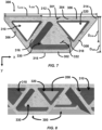
- FIG. 7 illustrates a block 300 according to such other embodiments.
- the block 300 comprises a front wall 302, a back wall 304, a first sidewall 306, and a second sidewall 308.
- the block 300 further comprises a first inner wall 316 and a second inner wall 318.
- the first inner wall 316 and the second inner wall 318 are provided to at least partially define three openings 310, 320, 330.
- the first inner wall 316 separates a first opening 310 from a third opening 330.
- the second inner wall 318 separates a second opening 320 from the third opening 330.
- the size of the first opening 310 is established at least in part by the location of the first inner wall 316 relative to the back wall 304 and the first sidewall 306. As best illustrated in FIG. 7 , the first inner wall 316 intersects (e.g., meets) the back wall 304 at a lateral distance L 310 measured in the x-direction from a first side surface 314 of the back wall 304, and the first inner wall 316 intersects the first sidewall 306 at a lateral distance D 310 measured in the y-direction from the rear surface 312 of the back wall 304.
- the first opening 310 and the second opening 320 have substantially the same size and shape. Accordingly, the second inner wall 318 intersects the back wall 304 at a lateral distance measured in the x-direction from a second side surface 314 of the back wall 304 which is substantially the same as the lateral distance D 310 , and the second inner wall 318 intersects the second sidewall 308 at a lateral distance measured in the y-direction from the rear surface 312 of the back wall 304 which is substantially the same as the lateral distance D 310 .
- the lateral distance L 310 is selected to be greater than or equal to 35% of the length L 300 of the block 300. More particularly, the lateral distance L 310 is selected to be greater than or equal to 35% of the length L 300 of the block 100 and less than or equal to about 43% of the length L 300 of the block 300 and, preferably, may be about 42% of the length L 300 of the block 300.
- the lateral distance L 310 according to one embodiment may be 0.23 m and the length L 300 of the block 300 may be 0.55 m.
- the lateral distance D 310 is selected to be greater than 50% of the depth D 300 of the block 300. More particularly, the lateral distance D 310 is selected to be greater than or equal to 53% of the depth D 300 of the block 300 and less than or equal to about 65% of the depth D 300 of the block 300 and, preferably, may be about 64% of the D 300 of the block 300.
- lateral distance D 310 according to one embodiment may be 0.16 m and the depth D 300 of the block 300 may be 0.25 m.
- the blocks 100, 300 may be formed of a concrete composition.
- concrete composition refers to a composition comprising hydraulic binder and aggregates which in presence of water forms a paste which sets and hardens by means of hydration reactions and processes and which, after hardening, retains its strength and stability even under water.
- concrete is as defined in standard NF EN 197-1 Standard of April 2012, preferably cement of the types CEM I, CEM II, CEM III, CEM IV or CEM V.
- the said suitable cement can be a mixture of a CEM I type with any one or several constituents listed in the European Standard of April 2012.
- hydroaulic binder refers to a material which sets and hardens by hydration, for example a cement.
- the concrete composition is based on cement comprising Portland clinker.
- Calcium sulphate is commonly added to Portland clinker to prepare a Portland cement.
- Calcium sulphate includes gypsum (calcium sulphate dihydrate, CaSO 4 .2H 2 O), hemi-hydrate (CaSO 4 .1/2H 2 O), anhydrite (anhydrous calcium sulphate, CaSO 4 ) or a mixture thereof.
- hydraulic binder may also comprise other mineral components often called “supplementary cementitious materials (SCM)", in particular slag, fly ash, calcined clays, limestone, pozzolan, metakaolin, cement kiln dust, and mixtures thereof, preferably at a content comprised between 6 and 50 wt.-% of the total hydraulic binder.
- SCM supplementary cementitious materials
- the aggregates may have a maximum size of 10 mm and, preferably, have a maximum size of 6 mm.
- the aggregates can comprise gravel and sand.
- the sand may have a maximum size of 2 mm and, preferably, a maximum size of 1 mm.
- the sand may have a minimum size of greater than 0 mm or of 0.063 mm.
- the water to binder ratio is preferably between 0.18 and 0.35 and, more preferably between 0.20 and 0.30.
- water includes the water added for mixing and eventually the water of the admixtures.
- the concrete material may be porous.
- the porosity of the concrete material is selected such that water may flow through the first side wall 106, 306, the second side wall 108, 308, the first inner wall 116, 316, and the second inner wall 118, 318 of the block 100, 300 as explained in further detail below.
- the porosity of the concrete material of the blocks may be in a range from 15% to 25%, inclusive.
- the front surface 115, 315 of the front wall 102, 302 may have a sealant material thereon.
- the sealant material is configured to prevent evaporation of water from within the block 100, 300.
- the sealing material may be a mortar sealant or an organic sealant.
- FIG. 3 illustrates the block 100 of FIG. 1 and the outline in dashed lines of a portion of two additional blocks 100a, 100b arranged over the block 100c. The dashed lines are equally representative of two additional blocks 100a, 100b arranged below the block 100c.
- FIG. 4 is a top view of a wall 200 of blocks 100.
- FIGS. 5 and 6 are perspective views of the wall 200 of blocks 100.
- FG. 8 is a top view of a wall 200 constructed of blocks 300.
- the wall 200 comprises at least two rows 202 of blocks 100. Each row 202 may comprise at least one block 100.
- the blocks 100 may be arranged in a block laying patterned known as a "stretcher bond."
- each block 200 of a first row 202a is offset by a half block relative to another block 200 of a second row 202b located vertically adjacent to the first row 202a.
- two laterally adjacent blocks 100 in the first row 202a are disposed against one another at the side surfaces 114 thereof intermediately along the length L 100 of a block 100 in the second row 202b.
- the blocks 100 of every other row 202 of blocks 100 are vertically aligned.
- the wall 200 may be constructed on a preexisting structure.
- the wall 200 is constructed on a façade of a building or other structure having a substantially vertically extending surface.
- each block 100 may be coupled to the preexisting structure with mortar such that mortar is provided between the rear surface 112 of the block 100 and the preexisting structure.
- the rows 202 may be laid in sequence starting from a lowermost row 202c to an uppermost row 202d and are laid vertically one over the other.
- the lower surface 103 of one block 100 may be directly disposed on the upper surface 101 of a vertically adjacent block 100 or mortar may be provided between the vertically adjacent surfaces.
- the wall 200 may also be provided with a water source 220.
- the water source 220 may be part of a water collection system, such as a rainwater collecting system including a gutter or another collecting system provided naturally or artificially with water.
- the water source 220 is located vertically above the uppermost row 202d of the wall 200.
- two laterally adjacent upper blocks 100a and 100b are located vertically adjacent to a lower block 100c.
- Each of the blocks 100a, 100b, 100c is identical and includes elements previously discussed with reference to FIGS. 1 and 2 .
- similar elements of the first block 100a are identified with an a
- similar elements of the second block 100b are identified with a b
- similar elements of the third block 100c are identified with a c.
- the respective lower surfaces 103 of the upper blocks 100a, 100b are disposed over (e.g., on) the upper surface 101 of the lower block 100c.
- the first upper block 100a and second upper block 100b contact each other at the side surfaces 114 intermediately along the length L 100 of the lower block 100c.
- the blocks 100a, 100b, 100c are configured and arranged such that openings 110, 120 of vertically adjacent blocks 100 form a channel 208 extending from an upper surface of the upper block to the lower surface of the lower block.
- the second opening 120a of the first block 100a overlaps with the first opening 110c of the lower block 100c
- the first opening 110b of the second block 100b overlaps with the second opening 120c of the lower block 100c.
- This channel 208 extends from the upper surface 101 of a block 100 in the uppermost row 202d to the lower surface 103 of a block 100 in a lowermost row 202c.
- the blocks 100a, 100b, 100c are configured and arranged such that the second opening 120a of the first block 100a overlaps with the third opening 130c of the lower block 100c, and the first opening 110b of the second upper block 100b overlaps with the third opening 130c of the lower block 100c.
- a first gap 204 is visible between an inner surface of the second sidewall 108a of the first upper block 100a and an inner surface of the first inner wall 116c of the lower block 100c
- a second gap 206 is visible between an inner surface of the first sidewall 106b of the second upper block 100b and an inner surface of the second inner wall 118c of the lower block 100c.
- the size of the first opening 110 and the second openings 120 may be modified by adjusting the lateral distance L 110 as a function of the length L 100 of the block 100, adjusting the lateral distance D 110 as a function of the depth D 100 of the block 100, and/or adjusting the thickness of the first and second inner walls 116, 118. Adjusting the size of the openings 110, 120 may also modify the size of the first gap 204 and the second gap 206.
- the upper surface of the first inner wall 116c and of the second inner wall 118c of the lower block 100c may be exposed within the channel 208.
- the block 300 is configured such that, when a plurality of blocks 300 are arranged to form the wall 200, openings 310, 320 of vertically adjacent blocks 300 also form a channel 208 extending from an upper surface of the upper block to the lower surface of the lower block. More particularly, the second opening 320 of a first block 300 overlaps with the first opening 310 of a vertically adjacent second block 300. Unlike the blocks 100, when a plurality of blocks 300 are arranged to form the wall 200, the openings 310, 320 do not overlap with the third opening 330 of a vertically adjacent block.
- the second inner wall 318 of the first block 300 is disposed directly over or under the first sidewall 306 of a vertically adjacent block 300, and the first inner wall 316 of the first block 300 will be disposed directly over or under the second sidewall 308 of a vertically adjacent block 300.
- upper surfaces of the first inner wall 316 and of the second inner wall 318 of the blocks 300 are not exposed within the channel 208.
- the columns 208 of the wall 200 formed from blocks 300 may be considered aligned.
- An axis extending along the z-axis centrally through the openings 310, 320 of a given block 300 is aligned (e.g., coaxial) with the respective to a corresponding z-axis in a vertically adjacent block 300.
- the third opening 130, 330 of the blocks 100, 300 may be at least partially filled with soil or other material supportive of vegetation growth.
- the third opening 130, 330 may further comprise seeds and/or a vegetation within the soil.
- the third opening 130, 330 is substantially uncovered at the upper surface 101, 301 allowing vegetation to be exposed to rain water and sun for growth.
- a water-absorbent material may be disposed within the blocks 100, 300.
- Water-absorbent materials may include perlite, vermiculite, an expanded clay aggregate, a superabsorbent polymer, and the like. Such water-absorbent materials are useful to maintain moisture within the wall 200.
- the water-absorbent material is provided within the first openings 110, 310 and the second openings 120, 320 such that each channel 208 of the wall 200 is substantially filled with the water-absorbent material.
- the water-absorbent material may be disposed on and/or adjacent to surfaces the first inner walls 116, 316 and the second inner walls 118, 318 and the first sidewalls 106, 306 and the second sidewalls 108, 308.
- the third opening 130, 330 may also comprises the water-absorbent material.
- the water-absorbent material may be disposed within the portion of the third opening 130 in the gaps 204, 206.
- the blocks 100, 300 when assembled to form the wall 200 create an integral water system for maintaining vegetation. Put differently, assembly of the blocks 100, 300 simultaneously constructs the wall 200 in which vegetation is planted and grown and creates the watering system for maintaining the planted vegetation. Thus, construction of the wall 200 does not require the additional incorporation of a separate watering system to direct the flow of water to the openings 130, 330 and the vegetation therein.
- water is provided into the wall 200 by the water source 220.
- the water source 220 may direct the flow of water into the channels 208. Water flows naturally (e.g., by gravity) through the channels 208.
- the water As water flows along surfaces of the blocks 100, 300 within the channels 208, the water is absorbed by the water-absorbent material provided in channels 208 of the blocks 100. Water absorbed by the water-absorbent material subsequently permeates through the first inner walls 116, 316 and second inner walls 118, 318 so as to provide water to the soil and vegetation in the third openings 130. Some water may also flow directly into the third openings 130 flows into the wall 200 from the channel 208 by flowing into the gaps 204, 206. Some water absorbed by the water-absorbent material may also be maintained within the water-absorbent material, thereby maintaining a sufficient level of humidity within the wall 200 to encourage vegetation maintenance and growth.
- the optional sealant material provided on the front surface 115, 315 of the block 100, 300 may also limit the evaporation of water from within the third opening 130, 330 and otherwise facilitate maintenance of a sufficient level of humidity within the wall 200.
Landscapes
- Engineering & Computer Science (AREA)
- Architecture (AREA)
- Civil Engineering (AREA)
- Structural Engineering (AREA)
- Life Sciences & Earth Sciences (AREA)
- Environmental Sciences (AREA)
- Revetment (AREA)
Abstract
Description
- The present disclosure relates generally to a block for constructing a vegetation wall and to the vegetation wall constructed therefrom.
- Heat islands are urbanized areas that experience higher temperatures than outlying areas. Structures such as buildings, roads, and other infrastructure absorb and re-emit the sun's heat more than natural landscapes such as forests and water bodies.
- Rendering construction elements, such as buildings, green is a practice that is becoming increasingly widespread and increasingly sought after to reduce the heat island effect. In addition, rendering construction elements green is a sought-after practice for aesthetic, thermal or phonic insulation and air or water quality reasons. The covering of surfaces with vegetation thus makes a real contribution to the quality of life of inhabitants of urban areas.
- Generally speaking, existing green wall structures are considered luxury items due to the significant costs of maintaining the wall and the vegetation disposed therein. The cost per square meter of green wall structures can amount to several hundred euros per year. One maintenance feature is watering of the vegetation of the wall. Existing green wall structures often require the integration of complex irrigation systems therein to support and grow the vegetation.
- Thus, there is a need to develop a technology for rendering construction elements green having both a reduce cost of initial construction and reduced upkeep cost, especially with respect to the watering of vegetation of the wall.
- One objective of the present disclosure is to provide a block used for construction of a vegetation wall. As explained in further detail below, each block is configured such that, when a plurality of blocks are assembled together, a watering system is integrally formed therewith. Accordingly, the cost of construction and maintenance of the wall is reduced relative to the vegetation walls requiring separately integrating irrigation or watering systems.
- To this end, the invention proposes a block for supporting vegetation growth comprising a back wall, a front wall, a first sidewall extending between and connecting the back wall and the front wall, and a second sidewall extending between and connecting the back wall and the front wall. The block further comprises a first inner wall extending from the back wall to the first sidewall. The first inner wall, the back wall, and the first sidewall collectively define a first opening. The first inner wall intersects the back wall at a lateral distance measured from a first side surface of the back wall that is greater than about 33% and less than about 45% of the length of the back wall. The first inner wall intersects the first sidewall at a lateral distance measured from a rear surface of the back wall that is greater than about 50% and less than or equal to about 65% of a depth of the block. The block further comprises a second inner wall extending from the back wall to the second sidewall. The second inner wall, the back wall, and the second sidewall collectively defining a second opening. The second inner wall intersects the back wall at a lateral distance measured from a second side surface of the back wall that is greater than about 33% and less than about 45% of the length of the back wall. The second inner wall intersects the second sidewall at a lateral distance measured from the rear surface of the back wall that is greater than about 50% and less than or equal to about 65% of the depth of the block. The back wall, the front wall, the first sidewall, the second sidewall, the first inner wall, and the second sidewall collectively define a third opening.
- Certain preferred but non-limiting features of the block described above are the following, taken individually or in combination:
- the first inner wall extends parallel to the second sidewall, and the second inner wall extends parallel to the first sidewall;
- the front wall extends parallel to the back wall;
- the first sidewall and the second sidewall extend in a converging manner from the back wall to the front wall;
- each of the first opening and the second opening extends through the block such that each of the first opening and the second opening is open at both an upper surface and a lower surface of the block;
- the third opening has a base such that the third opening is open at the upper surface of the block and closed at the lower surface of the block; and/or
- the block is composed of a porous concrete material.
- Another objective of the present disclosure is to provide a wall comprising a plurality of the blocks described above. The plurality of blocks comprising a first block and a second block in a first row and a third block in a second row, and the first row is located vertically adjacent to the second row. The first block, the second block, and the third block are arranged such that the first block and the second block are disposed over an upper surface of the third block. The first block and the second block are disposed against each other on a side surface of the respective back walls thereof and meet intermediately along a length of the back wall of the third block. The second opening of the first block overlaps with the first opening of the third block and the first opening of the second block overlaps with the second opening of the third block. The respectively overlapping first and second openings collectively form a channel. Each channel extends vertically through the first and second rows such that water is able to flow to each row.
- Certain preferred but non-limiting features of the block described above are the following, taken individually or in combination:
- the second opening of the first block also overlaps with the third opening of the third block such that, when the first and third blocks are viewed in a top view of the upper surfaces thereof, a first gap is visible between an inner surface of the second sidewall of the first block and an inner surface of the first inner wall of the third block;
- the first opening of the second block also overlaps with the third opening of the third block such that, when the second and third blocks are viewed in a top view of the upper surfaces thereof, a second gap is visible between an inner surface of the first sidewall of the second block and an inner surface of the second inner wall of the third block;
- the second inner wall of the first block is disposed over the first sidewall of the third block such that the second opening of the first block is aligned with the first opening of the third block, and wherein the first inner wall of the second block is disposed over the second sidewall of the third block such that the first opening of the second block is aligned with the second opening of the third block;
- the third opening of the third block comprises soil and vegetation;
- a water-absorbent material is disposed in the channels;
- the plurality of blocks are disposed on a vertical surface of a pre-existing structure; and/or
- the wall further comprises a water collection system, the water collection system configured to direct water into the channel.
- The illustrations presented herein are not meant to be actual views of any particular component, device, or system, but are merely idealized representations which are employed to describe embodiments of the present invention. Other features, goals, and advantages of the present invention will appear more clearly upon reading of the detailed description that follows and with references to drawings provided by way of non-limiting examples wherein:
-
FIGS. 1 and 2 are a schematic, top view and perspective view of a block, respectively; -
FIGS. 3 and 4 are schematic tops views of an assembly of the blocks as illustrated inFIGS. 1 and 2 ; -
FIGS. 5 and 6 are perspective views of a wall constructed from the blocks ofFIG. 1 ; -
FIG. 7 is a schematic top view of a block; and -
FIG. 8 is a top view of an assembly of blocks as illustrated inFIG. 7 . - As used herein, spatially relative terms, such as "below," "lower," "above," "over," "upper," "top," "front," "rear," "left," "right," and the like, may be used for ease of description to describe one element's or feature's relationship to another element(s) or feature(s) as illustrated in the figures. Unless otherwise specified, the spatially relative terms are intended to encompass different orientations of the devices in addition to the orientation depicted in the figures. For example, if devices in the figures are inverted, elements described as "upper" or "on" other elements or features would then be oriented "lower" or "under" the other elements or features.
- As used herein, the term "substantially" in reference to a given parameter, property, or condition means and includes to a degree that one of ordinary skill in the art would understand that the given parameter, property, or condition is met with a degree of variance, such as within acceptable manufacturing tolerances.
- As used herein, the term "about" in reference to a given parameter is inclusive of the stated value and has the meaning dictated by the context (e.g., it includes the degree of error associated with measurement of the given parameter).
- As used herein, the term "and/or" includes any and all combinations of one or more of the associated listed items.
- As used herein, the terms "comprising," "including," "containing," and grammatical equivalents thereof are inclusive or open-ended terms that do not exclude additional, unrecited elements or method steps, but also include the more restrictive terms "consisting of' and "consisting essentially of' and grammatical equivalents thereof.
- As used herein, the term "configured" refers to a size, shape, orientation, and arrangement of at least one structure and at least one apparatus facilitating operation of the structure or the apparatus in a pre-determined way.
-
FIGS. 1-3 illustrate ablock 100 according to embodiments of the present disclosure.FIGS. 4-6 illustrate awall 200 favorable to the growth of vegetation formed from a plurality of theblocks 100 as will be explained in further detail below. - The
block 100 is a unitary structure defining a plurality of openings. As used herein, the term "unitary structure" means a structure formed as a single piece or single unit. - The
block 100 comprises afront wall 102, aback wall 104, afirst sidewall 106, and asecond sidewall 108. The first andsecond sidewalls front wall 102 and theback wall 104. Collectively, thefront wall 102, theback wall 104, thefirst sidewall 106, and thesecond sidewall 108 define a perimeter of theblock 100. - A coordinate system is illustrated in
FIGS. 1 and 2 . As used herein, the terms "axial," "axially," "vertical," "vertically," "longitudinal," and "longitudinally" generally mean and refer to a direction along or parallel to the z-direction in the coordinate system. Thus, the vertical direction is a direction extending from anupper surface 101 to alower surface 103 of theblock 100 described herein. As used herein, the term "height" refers to a dimension measured in the z-direction. As used herein, the terms "horizontal," "horizontally," "lateral" and "laterally" generally means and refers to a direction along or parallel to either the x-direction or y-direction. Thus, the lateral direction is a direction parallel to a plane in which theupper surface 101 of theblock 100 lies. The lateral direction is perpendicular to the vertical or longitudinal direction. - A
rear surface 112 of theback wall 104 may be disposed on or over a structure on which thewall 200 is to be constructed. Side surfaces 114 of theback wall 104 may be disposed against a side surface of a laterallyadjacent block 100 when a plurality ofblocks 100 are assembled together to form thewall 200. - As used herein, the term "length" refers to a direction along or parallel to the x-direction in the coordinate system. The length L104 refers to a maximum length of the
block 100, which is measured along theback wall 104. The length L102 refers to a minimum length of theblock 100, which is measured along thefront wall 102. - As used herein, the term "depth" refers to a direction along or parallel to the y-direction in the coordinate system. The depth D100 refers to a maximum depth of the
block 100, which is measure between arear surface 112 of theback wall 104 and afront surface 115 of thefront wall 102. - The
first sidewall 106, thesecond sidewall 108, thefront wall 102 and theback wall 104 may be dimensioned and/or arranged such that theblock 100 decreases in length between theback wall 104 and thefront wall 102. - The
front wall 102 andback wall 104 may extend parallel to each other. Thefront wall 102 is shorter in length than theback wall 104. In some embodiments, the length L102 of thefront wall 102 may be between 40% and 60% of the length of the back wall 104 (i.e., the length L100 of the block 100) and, more particularly, the length L102 may be about 50% of the length of theback wall 104. - The
first sidewall 106 and thesecond sidewall 108 extend in a converging manner as thesidewalls back wall 104 to thefront wall 102. Accordingly, theblock 100 may taper in length between theback wall 104 and thefront wall 102. - By way of non-limiting example, the length L104 of the
back wall 104 may be 0.55 m and the length L102 of thefront wall 102 may be 0.23 m according to one embodiment. - The
block 100 further comprises a firstinner wall 116 and a secondinner wall 118. The firstinner wall 116 and the secondinner wall 118 are provided to at least partially define threeopenings inner wall 116 separates afirst opening 110 from athird opening 130. The secondinner wall 118 separates asecond opening 120 from thethird opening 130. - The first
inner wall 116 extends from theback wall 104 to thefirst sidewall 106. The firstinner wall 116 extends parallel to thesecond sidewall 108. Thefirst opening 110 is defined by (e.g., bounded by) the firstinner wall 116, a portion of thefirst sidewall 106, and a portion of theback wall 104. - The second
inner wall 118 extends from theback wall 104 to thesecond sidewall 108. The secondinner wall 118 extends parallel to thefirst sidewall 106. Thesecond opening 120 is defined by the secondinner wall 118, a portion of thesecond sidewall 108, and a portion of theback wall 104. - The
first opening 110 and thesecond opening 120 may be generally triangular in shape. More particularly, thefirst opening 110 and thesecond opening 120 may have the shape of an isosceles triangles. The base of the triangular shapedopenings openings openings back wall 104. The corners of the triangle may be rounded so as to reduce stress concentrations. - The size of the
first opening 110 is established at least in part by the location of the firstinner wall 116 relative to theback wall 104 and thefirst sidewall 106. As best illustrated inFIG. 3 , the firstinner wall 116 intersects (e.g., meets) theback wall 104 at a lateral distance L110 measured in the x-direction from a first side surface 114' of theback wall 104, and the firstinner wall 116 intersects thefirst sidewall 106 at a lateral distance D110 measured in the y-direction from therear surface 112 of theback wall 104. - The lateral distance L110 is selected to be greater than 33% of the length L100 of the
block 100. More particularly, the lateral distance L110 is selected to be greater than 33% of the length L100 of theblock 100 and less than about 40% of the length L100 of theblock 100 and, preferably, may be about 34% of the length L100 of theblock 100. By way of non-limiting example, the lateral distance L110 according to one embodiment may be 0.19 m and the length L100 of theblock 100 may be 0.55 m. - The lateral distance D110 is selected to be greater than or equal to 50% of the depth D100 of the
block 100. More particularly, the lateral distance D110 is selected to be greater than or equal to 50% of the depth D100 of theblock 100 and less than or equal to about 60% of the depth D100 of theblock 100 and, preferably, may be about 52% of the D100 of theblock 100. By way of non-limiting example, lateral distance D110 according to one embodiment may be 0.13 m and the depth D100 of theblock 100 may be 0.25 m. - The
block 100 as illustrated and described with reference toFIGS. 1-3 are designed such that when a plurality ofblocks 100 are assembled together, first andsecond openings adjacent blocks 100 overlap to formchannels 208, as illustrated inFIGS. 4 and5 . In such embodiments, the first andsecond openings third opening 130 is exposed within thechannel 208 to formgaps Such channels 208 may be considered staggered as an axis extending along the z-axis centrally through theopenings - In other embodiments, a block may be configured such the location of the inner walls separating the first opening from the third opening and the second opening from the third opening is such that the first and second openings of vertically
adjacent blocks 100 overlap to form channels in an aligned manner whereingaps FIG. 7 illustrates ablock 300 according to such other embodiments. - Due to similarities between the
block 100 and theblock 300, elements common to theblock 100 are referred to with similar numerals within the 300-series of numbers with reference to theblock 300. - The
block 300 comprises afront wall 302, aback wall 304, afirst sidewall 306, and asecond sidewall 308. Theblock 300 further comprises a firstinner wall 316 and a secondinner wall 318. The firstinner wall 316 and the secondinner wall 318 are provided to at least partially define threeopenings inner wall 316 separates afirst opening 310 from athird opening 330. The secondinner wall 318 separates asecond opening 320 from thethird opening 330. - The size of the
first opening 310 is established at least in part by the location of the firstinner wall 316 relative to theback wall 304 and thefirst sidewall 306. As best illustrated inFIG. 7 , the firstinner wall 316 intersects (e.g., meets) theback wall 304 at a lateral distance L310 measured in the x-direction from afirst side surface 314 of theback wall 304, and the firstinner wall 316 intersects thefirst sidewall 306 at a lateral distance D310 measured in the y-direction from therear surface 312 of theback wall 304. - The
first opening 310 and thesecond opening 320 have substantially the same size and shape. Accordingly, the secondinner wall 318 intersects theback wall 304 at a lateral distance measured in the x-direction from asecond side surface 314 of theback wall 304 which is substantially the same as the lateral distance D310, and the secondinner wall 318 intersects thesecond sidewall 308 at a lateral distance measured in the y-direction from therear surface 312 of theback wall 304 which is substantially the same as the lateral distance D310. - The lateral distance L310 is selected to be greater than or equal to 35% of the length L300 of the
block 300. More particularly, the lateral distance L310 is selected to be greater than or equal to 35% of the length L300 of theblock 100 and less than or equal to about 43% of the length L300 of theblock 300 and, preferably, may be about 42% of the length L300 of theblock 300. By way of non-limiting example, the lateral distance L310 according to one embodiment may be 0.23 m and the length L300 of theblock 300 may be 0.55 m. - The lateral distance D310 is selected to be greater than 50% of the depth D300 of the
block 300. More particularly, the lateral distance D310 is selected to be greater than or equal to 53% of the depth D300 of theblock 300 and less than or equal to about 65% of the depth D300 of theblock 300 and, preferably, may be about 64% of the D300 of theblock 300. By way of non-limiting example, lateral distance D310 according to one embodiment may be 0.16 m and the depth D300 of theblock 300 may be 0.25 m. - The
blocks - As used herein, the term "hydraulic binder" refers to a material which sets and hardens by hydration, for example a cement.
- Specifically, the concrete composition is based on cement comprising Portland clinker.
- Calcium sulphate is commonly added to Portland clinker to prepare a Portland cement.
- Calcium sulphate includes gypsum (calcium sulphate dihydrate, CaSO4.2H2O), hemi-hydrate (CaSO4.1/2H2O), anhydrite (anhydrous calcium sulphate, CaSO4) or a mixture thereof.
- Further, the hydraulic binder may also comprise other mineral components often called "supplementary cementitious materials (SCM)", in particular slag, fly ash, calcined clays, limestone, pozzolan, metakaolin, cement kiln dust, and mixtures thereof, preferably at a content comprised between 6 and 50 wt.-% of the total hydraulic binder.
- Any known aggregates suitable for the preparation of concrete may be used for the concrete composition. The aggregates may have a maximum size of 10 mm and, preferably, have a maximum size of 6 mm.
- The aggregates can comprise gravel and sand.
- Any known sand suitable for the preparation of concrete is suitable for the concrete composition. The sand may have a maximum size of 2 mm and, preferably, a maximum size of 1 mm. The sand may have a minimum size of greater than 0 mm or of 0.063 mm.
- The water to binder ratio is preferably between 0.18 and 0.35 and, more preferably between 0.20 and 0.30.
- As used herein, the term "water" includes the water added for mixing and eventually the water of the admixtures.
- The concrete material may be porous. The porosity of the concrete material is selected such that water may flow through the
first side wall second side wall inner wall inner wall block - In some embodiments, the
front surface front wall block - A plurality of
blocks 100 or a plurality ofblocks 300 having a design as described herein may be stacked together to form a vertical construction (e.g., wall 200).FIG. 3 illustrates theblock 100 ofFIG. 1 and the outline in dashed lines of a portion of twoadditional blocks block 100c. The dashed lines are equally representative of twoadditional blocks block 100c.FIG. 4 is a top view of awall 200 ofblocks 100.FIGS. 5 and 6 are perspective views of thewall 200 ofblocks 100. FG. 8 is a top view of awall 200 constructed ofblocks 300. - For clarity of this disclosure, construction of the
wall 200 will be described primarily with reference to block 100 except when construction of thewall 200 usingblocks 300 differs from construction of thewall 200 usingblocks 100. Otherwise, the skilled person will understand that thewall 200 can be equally be constructed with a plurality ofblocks 300 as shown and described with reference toFIGS. 7 and 8 . Thewall 200 comprises at least tworows 202 ofblocks 100. Eachrow 202 may comprise at least oneblock 100. - As best illustrated in
FIGS. 4 and5 , theblocks 100 may be arranged in a block laying patterned known as a "stretcher bond." In this arrangement, eachblock 200 of afirst row 202a is offset by a half block relative to anotherblock 200 of asecond row 202b located vertically adjacent to thefirst row 202a. Put differently, two laterallyadjacent blocks 100 in thefirst row 202a are disposed against one another at the side surfaces 114 thereof intermediately along the length L100 of ablock 100 in thesecond row 202b. Further, in this arrangement, theblocks 100 of everyother row 202 ofblocks 100 are vertically aligned. - The
wall 200 may be constructed on a preexisting structure. For example, thewall 200 is constructed on a façade of a building or other structure having a substantially vertically extending surface. In construction, eachblock 100 may be coupled to the preexisting structure with mortar such that mortar is provided between therear surface 112 of theblock 100 and the preexisting structure. - The
rows 202 may be laid in sequence starting from alowermost row 202c to anuppermost row 202d and are laid vertically one over the other. Thelower surface 103 of oneblock 100 may be directly disposed on theupper surface 101 of a verticallyadjacent block 100 or mortar may be provided between the vertically adjacent surfaces. - The
wall 200 may also be provided with awater source 220. Thewater source 220 may be part of a water collection system, such as a rainwater collecting system including a gutter or another collecting system provided naturally or artificially with water. Thewater source 220 is located vertically above theuppermost row 202d of thewall 200. - With continued reference to
FIG. 3 , two laterally adjacentupper blocks lower block 100c. Each of theblocks FIGS. 1 and 2 . For convenience of explanation and illustration, similar elements of thefirst block 100a are identified with an a, similar elements of thesecond block 100b are identified with a b, and similar elements of thethird block 100c are identified with a c. - When the
blocks wall 200, the respectivelower surfaces 103 of theupper blocks upper surface 101 of thelower block 100c. The firstupper block 100a and secondupper block 100b contact each other at the side surfaces 114 intermediately along the length L100 of thelower block 100c. - The
blocks openings adjacent blocks 100 form achannel 208 extending from an upper surface of the upper block to the lower surface of the lower block. As best illustrated inFIG. 3 , thesecond opening 120a of thefirst block 100a overlaps with thefirst opening 110c of thelower block 100c, and thefirst opening 110b of thesecond block 100b overlaps with thesecond opening 120c of thelower block 100c. Thischannel 208 extends from theupper surface 101 of ablock 100 in theuppermost row 202d to thelower surface 103 of ablock 100 in alowermost row 202c. - In addition, the
blocks second opening 120a of thefirst block 100a overlaps with the third opening 130c of thelower block 100c, and thefirst opening 110b of the secondupper block 100b overlaps with the third opening 130c of thelower block 100c. When these openings overlap and when theblocks upper surface 100 of theblocks first gap 204 is visible between an inner surface of thesecond sidewall 108a of the firstupper block 100a and an inner surface of the firstinner wall 116c of thelower block 100c, and asecond gap 206 is visible between an inner surface of thefirst sidewall 106b of the secondupper block 100b and an inner surface of the secondinner wall 118c of thelower block 100c. - The size of the
first opening 110 and thesecond openings 120 and may be modified by adjusting the lateral distance L110 as a function of the length L100 of theblock 100, adjusting the lateral distance D110 as a function of the depth D100 of theblock 100, and/or adjusting the thickness of the first and secondinner walls openings first gap 204 and thesecond gap 206. - As illustrated in
FIG. 3 and 4 , the upper surface of the firstinner wall 116c and of the secondinner wall 118c of thelower block 100c may be exposed within thechannel 208. - The
block 300 is configured such that, when a plurality ofblocks 300 are arranged to form thewall 200,openings adjacent blocks 300 also form achannel 208 extending from an upper surface of the upper block to the lower surface of the lower block. More particularly, thesecond opening 320 of afirst block 300 overlaps with thefirst opening 310 of a vertically adjacentsecond block 300. Unlike theblocks 100, when a plurality ofblocks 300 are arranged to form thewall 200, theopenings third opening 330 of a vertically adjacent block. The secondinner wall 318 of thefirst block 300 is disposed directly over or under thefirst sidewall 306 of a verticallyadjacent block 300, and the firstinner wall 316 of thefirst block 300 will be disposed directly over or under thesecond sidewall 308 of a verticallyadjacent block 300. Thus, upper surfaces of the firstinner wall 316 and of the secondinner wall 318 of theblocks 300 are not exposed within thechannel 208. - Unlike the
columns 208 of awall 200 formed fromblocks 100, thecolumns 208 of thewall 200 formed fromblocks 300 may be considered aligned. An axis extending along the z-axis centrally through theopenings block 300 is aligned (e.g., coaxial) with the respective to a corresponding z-axis in a verticallyadjacent block 300. - During or after construction of the
wall 200, thethird opening blocks third opening - Due to the arrangement of the
blocks third opening upper surface - A water-absorbent material may be disposed within the
blocks wall 200. - The water-absorbent material is provided within the
first openings second openings channel 208 of thewall 200 is substantially filled with the water-absorbent material. When the water-absorbent material is provided in thechannel 208, the water-absorbent material may be disposed on and/or adjacent to surfaces the firstinner walls inner walls first sidewalls second sidewalls gaps third opening third opening 130 in thegaps - The
blocks wall 200 create an integral water system for maintaining vegetation. Put differently, assembly of theblocks wall 200 in which vegetation is planted and grown and creates the watering system for maintaining the planted vegetation. Thus, construction of thewall 200 does not require the additional incorporation of a separate watering system to direct the flow of water to theopenings - In operation, water is provided into the
wall 200 by thewater source 220. Thewater source 220 may direct the flow of water into thechannels 208. Water flows naturally (e.g., by gravity) through thechannels 208. - As water flows along surfaces of the
blocks channels 208, the water is absorbed by the water-absorbent material provided inchannels 208 of theblocks 100. Water absorbed by the water-absorbent material subsequently permeates through the firstinner walls inner walls third openings 130. Some water may also flow directly into thethird openings 130 flows into thewall 200 from thechannel 208 by flowing into thegaps wall 200 to encourage vegetation maintenance and growth. The optional sealant material provided on thefront surface block third opening wall 200. - While the disclosed device structures and methods are susceptible to various modifications and alternative forms in implementation thereof, specific embodiments have been shown by way of example in the drawings and have been described in detail herein. However, it should be understood that the present invention is not intended to be limited to the particular forms disclosed. Rather, the present invention encompasses all modifications, combinations, equivalents, variations, and alternatives falling within the scope of the present disclosure as defined by the following appended claims and their legal equivalents.
Claims (14)
- A block (100, 300) for supporting vegetation growth, comprising:a back wall (104, 304);a front wall (102, 302);a first sidewall (106, 306) extending between and connecting the back wall (104, 304) and the front wall (102, 302);a second sidewall (108, 308) extending between and connecting the back wall (104, 304) and the front wall (102, 302);a first inner wall (116, 316) extending from the back wall (104, 304) to the first sidewall (106, 306), the first inner wall (116, 316), the back wall (104, 304), and the first sidewall (106, 306) collectively defining a first opening (110, 310), wherein the first inner wall (116, 316) intersects the back wall (104, 304) at a lateral distance L110 measured from a first side surface (114, 314) of the back wall (104, 304) that is greater than about 33% and less than about 45% of the length L100 of the back wall (104, 304), the first inner wall (116, 316) intersects the first sidewall (106, 306) at a lateral distance measured from a rear surface (112, 312) of the back wall (104, 304) that is greater than about 50% and less than or equal to about 65% of a depth (D100) of the block (100, 300); anda second inner wall (118, 318) extending from the back wall (104, 304) to the second sidewall (108, 308), the second inner wall (118, 318), the back wall (104, 304), and the second sidewall (108, 308) collectively defining a second opening (120, 320), wherein the second inner wall (118, 318) intersects the back wall (104, 304) at a lateral distance L110 measured from a second side surface (114, 314) of the back wall (104, 304) that is greater than about 33% and less than about 45% of the length L104 of the back wall (104, 304), the second inner wall (118, 318) intersects the second sidewall (108, 308) at a lateral distance measured from the rear surface (112, 312) of the back wall (104, 304) that is greater than about 50% and less than or equal to about 65% of the depth (D100) of the block (100, 300),wherein the back wall (104, 304), the front wall (102, 302), the first sidewall (106, 306), the second sidewall (108, 308), the first inner wall (116, 316), and the second sidewall (118, 318) define a third opening (130, 330).
- The block (100, 300) of claim 1, wherein the first inner wall (116, 316) extends parallel to the second sidewall (108, 308), and the second inner wall (118, 318) extends parallel to the first sidewall (106, 306).
- The block (100, 300) of either of claims 1 or 2, wherein the front wall (102, 302) extends parallel to the back wall (104, 304).
- The block (100, 300) of any of claims 1-3, wherein the first sidewall (106, 306) and the second sidewall (108, 308) extend in a converging manner from the back wall (104, 304) to the front wall (102, 302).
- The block (100, 300) of any of claims 1-4, wherein each of the first opening (110, 310) and the second opening (120, 320) extends through the block (100, 300) such that each of the first opening (110, 310) and the second opening (120, 320) is open at both an upper surface (101, 301) and a lower surface (103, 303) of the block (100, 300).
- The block (100, 300) of any of claims 1-5, wherein the third opening (130, 330) has a base (132, 332) such that the third opening (130, 330) is open at the upper surface (101, 301) of the block (100, 300) and closed at the lower surface (103, 303) of the block (100, 300).
- The block (100, 300) of any of claims 1-6, wherein the block (100, 300) is composed of a porous concrete material.
- A wall (200) for vegetation growth, comprising:
a plurality of blocks (100, 300) according to any of claims 1-7, the plurality of blocks (100, 300) comprising a first block (100, 300) and a second block (100, 300) in a first row (202a) and a third block (100, 300) in a second row (202), the first row (202a) located vertically adjacent to the second row (202b), wherein the first block (100, 300), the second block (100, 300), and the third block (100, 300) arranged such that:the first block (100, 300) and the second block (100, 300) are disposed over an upper surface (101, 301) of the third block (100, 300), the first block (100, 300) and the second block (100, 300) disposed against each other on a side surface (114, 314) of the respective back walls (104, 304) thereof, wherein the first block (100, 300) and the second block (100, 300) meet intermediately along a length (L100) of the back wall (104, 304) of the third block (100, 300);the second opening (120, 320) of the first block (100, 300) overlaps with the first opening (110, 310) of the third block (100, 300) and the first opening (110, 310) of the second block (100, 300) overlaps with the second opening (120, 320) of the third block (100, 300), the overlapping first and second openings (110, 120) collectively forming a plurality of channels (208), each channel (208) extending vertically through the plurality of rows (202) such that water flows to each row (202) of the plurality. - The wall (200) of claim 8, wherein:the second opening (120) of the first block (100) overlaps with the third opening (110) of the third block (100) such that, when the first and third blocks are viewed in a top view of the upper surfaces (100) thereof, a first gap (204) is visible between an inner surface of the second sidewall (108) of the first block (100) and an inner surface of the first inner wall (116) of the third block (100), andthe first opening (110) of the second block (100) overlaps with the third opening (110) of the third block (100) such that, when the second and third blocks are viewed in a top view of the upper surfaces (100) thereof, a second gap (206) is visible between an inner surface of the first sidewall (106) of the second block (100) and an inner surface of the second inner wall (118) of the third block (100).
- The wall (200) of claim 8, wherein the second inner wall (318) of the first block (300) is disposed over the first sidewall (306) of the third block (300) such that the second opening (120) of the first block (300) is aligned with the first opening (110) of the third block (300), and wherein the first inner wall (316) of the second block (300) is disposed over the second sidewall (308) of the third block (300) such that the first opening (110) of the second block (300) is aligned with the second opening (120) of the third block (300).
- The wall (200) of any of claims 8-10, wherein the third opening (130c) of the third block (100, 300) comprises soil and vegetation.
- The wall (200) of any of claims 8-11, wherein a water-absorbent material is disposed in the channels (208).
- The wall (200) of any of claims 8-12, wherein the plurality of blocks (100, 300) are disposed on a vertical surface of a pre-existing structure.
- The wall (200) of any of claims 8-13, further comprising a water collection system, the water collection system configured to direct water into the channel (208).
Priority Applications (2)
| Application Number | Priority Date | Filing Date | Title |
|---|---|---|---|
| EP22305412.3A EP4253659B1 (en) | 2022-03-31 | 2022-03-31 | A block for a vegetation wall |
| PCT/EP2023/058473 WO2023187165A1 (en) | 2022-03-31 | 2023-03-31 | A block for a vegetation wall |
Applications Claiming Priority (1)
| Application Number | Priority Date | Filing Date | Title |
|---|---|---|---|
| EP22305412.3A EP4253659B1 (en) | 2022-03-31 | 2022-03-31 | A block for a vegetation wall |
Publications (2)
| Publication Number | Publication Date |
|---|---|
| EP4253659A1 true EP4253659A1 (en) | 2023-10-04 |
| EP4253659B1 EP4253659B1 (en) | 2026-04-29 |
Family
ID=81308414
Family Applications (1)
| Application Number | Title | Priority Date | Filing Date |
|---|---|---|---|
| EP22305412.3A Active EP4253659B1 (en) | 2022-03-31 | 2022-03-31 | A block for a vegetation wall |
Country Status (2)
| Country | Link |
|---|---|
| EP (1) | EP4253659B1 (en) |
| WO (1) | WO2023187165A1 (en) |
Citations (3)
| Publication number | Priority date | Publication date | Assignee | Title |
|---|---|---|---|---|
| WO2005113911A1 (en) * | 2004-05-17 | 2005-12-01 | Sf-Kooperation Gmbh Beton-Konzepte | Supporting wall and moulded blocks of concrete for building a supporting wall |
| US7818919B1 (en) * | 2008-12-07 | 2010-10-26 | Claudio Betances Maxwell-Merrill | Botanically studded edifice |
| US20120180388A1 (en) * | 2010-12-15 | 2012-07-19 | Jared Friedman | Vertical Planter and Gardening Wall |
-
2022
- 2022-03-31 EP EP22305412.3A patent/EP4253659B1/en active Active
-
2023
- 2023-03-31 WO PCT/EP2023/058473 patent/WO2023187165A1/en not_active Ceased
Patent Citations (3)
| Publication number | Priority date | Publication date | Assignee | Title |
|---|---|---|---|---|
| WO2005113911A1 (en) * | 2004-05-17 | 2005-12-01 | Sf-Kooperation Gmbh Beton-Konzepte | Supporting wall and moulded blocks of concrete for building a supporting wall |
| US7818919B1 (en) * | 2008-12-07 | 2010-10-26 | Claudio Betances Maxwell-Merrill | Botanically studded edifice |
| US20120180388A1 (en) * | 2010-12-15 | 2012-07-19 | Jared Friedman | Vertical Planter and Gardening Wall |
Also Published As
| Publication number | Publication date |
|---|---|
| WO2023187165A1 (en) | 2023-10-05 |
| EP4253659B1 (en) | 2026-04-29 |
Similar Documents
| Publication | Publication Date | Title |
|---|---|---|
| US6718722B2 (en) | Construction composition, structure, and method | |
| CN105246853A (en) | Fast-curing pervious concrete mix | |
| US12503394B2 (en) | Compositions, methods, and systems related to multi-modal distribution of vaterite particles | |
| CN111368361A (en) | BIM-based super-high-rise super-thick large-volume concrete one-time pouring construction method in hot climate | |
| CN117385886A (en) | Construction method of medical house radiation-proof concrete structure | |
| CN110387904B (en) | Ecological composite retaining wall structure and construction method thereof | |
| CN109736342A (en) | A kind of soil cement mattress layer and its construction method in hydraulic engineering composite foundation | |
| CN113445747A (en) | Rigid composite waterproof structure containing FJT waterproof compacting agent and construction method thereof | |
| EP4253659B1 (en) | A block for a vegetation wall | |
| CN110510975A (en) | A kind of fluidly terrace material and its application | |
| CN107217565A (en) | A kind of preparation method of colorful water-permeable mattess | |
| CN201024570Y (en) | Multifunctional hollow brick | |
| CN112412008A (en) | Seamless construction method for accurate slope finding of super-large concrete flat roof structure | |
| EP0990627A1 (en) | Hydraulic binder having reduced shrinkage and its use | |
| CN205637107U (en) | Sunken landscape balcony flower pond suitable for high-rise residential buildings | |
| US20260084977A1 (en) | Compositions, methods, and systems related to calcium carbonate blends | |
| CN207878714U (en) | A kind of sub- wall of assembled light concrete | |
| CN119041594A (en) | Green wall building of planting | |
| JP2005154265A (en) | Water-retentive concrete member | |
| DE19853196A1 (en) | Hydraulic binder with reduced shrinkage and its use | |
| CN209584980U (en) | A kind of four-way assembled ecology channel | |
| DE10137231A1 (en) | Medium-bed mortar for laying large-format floor slabs | |
| KR101139949B1 (en) | Lawn block | |
| CN212772783U (en) | Equipment platform structure of residential building | |
| CN211340283U (en) | Granite drainage paving structure |
Legal Events
| Date | Code | Title | Description |
|---|---|---|---|
| PUAI | Public reference made under article 153(3) epc to a published international application that has entered the european phase |
Free format text: ORIGINAL CODE: 0009012 |
|
| STAA | Information on the status of an ep patent application or granted ep patent |
Free format text: STATUS: THE APPLICATION HAS BEEN PUBLISHED |
|
| AK | Designated contracting states |
Kind code of ref document: A1 Designated state(s): AL AT BE BG CH CY CZ DE DK EE ES FI FR GB GR HR HU IE IS IT LI LT LU LV MC MK MT NL NO PL PT RO RS SE SI SK SM TR |
|
| P01 | Opt-out of the competence of the unified patent court (upc) registered |
Effective date: 20240222 |
|
| STAA | Information on the status of an ep patent application or granted ep patent |
Free format text: STATUS: REQUEST FOR EXAMINATION WAS MADE |
|
| 17P | Request for examination filed |
Effective date: 20240403 |
|
| RBV | Designated contracting states (corrected) |
Designated state(s): AL AT BE BG CH CY CZ DE DK EE ES FI FR GB GR HR HU IE IS IT LI LT LU LV MC MK MT NL NO PL PT RO RS SE SI SK SM TR |
|
| GRAP | Despatch of communication of intention to grant a patent |
Free format text: ORIGINAL CODE: EPIDOSNIGR1 |
|
| STAA | Information on the status of an ep patent application or granted ep patent |
Free format text: STATUS: GRANT OF PATENT IS INTENDED |
|
| INTG | Intention to grant announced |
Effective date: 20260126 |
|
| GRAS | Grant fee paid |
Free format text: ORIGINAL CODE: EPIDOSNIGR3 |
|
| GRAA | (expected) grant |
Free format text: ORIGINAL CODE: 0009210 |
|
| STAA | Information on the status of an ep patent application or granted ep patent |
Free format text: STATUS: THE PATENT HAS BEEN GRANTED |
|
| AK | Designated contracting states |
Kind code of ref document: B1 Designated state(s): AL AT BE BG CH CY CZ DE DK EE ES FI FR GB GR HR HU IE IS IT LI LT LU LV MC MK MT NL NO PL PT RO RS SE SI SK SM TR |
|
| REG | Reference to a national code |
Ref country code: CH Ref legal event code: F10 Free format text: ST27 STATUS EVENT CODE: U-0-0-F10-F00 (AS PROVIDED BY THE NATIONAL OFFICE) Effective date: 20260429 Ref country code: GB Ref legal event code: FG4D |
|
| RIN1 | Information on inventor provided before grant (corrected) |
Inventor name: MORIN, VINCENT Inventor name: DUBOIS-BRUGGER, ISABELLE Inventor name: DUCHAND, SYLVAIN Inventor name: JAY, PASCAL |