EP4249788B1 - Vorrichtung zur kanalrohrinspektion und/oder -sanierung einer von einem hauptkanal abzweigenden anschlussleitung - Google Patents
Vorrichtung zur kanalrohrinspektion und/oder -sanierung einer von einem hauptkanal abzweigenden anschlussleitung Download PDFInfo
- Publication number
- EP4249788B1 EP4249788B1 EP23150899.5A EP23150899A EP4249788B1 EP 4249788 B1 EP4249788 B1 EP 4249788B1 EP 23150899 A EP23150899 A EP 23150899A EP 4249788 B1 EP4249788 B1 EP 4249788B1
- Authority
- EP
- European Patent Office
- Prior art keywords
- carriage
- adapter
- joint
- guide element
- inspection
- Prior art date
- Legal status (The legal status is an assumption and is not a legal conclusion. Google has not performed a legal analysis and makes no representation as to the accuracy of the status listed.)
- Active
Links
Images

Classifications
-
- F—MECHANICAL ENGINEERING; LIGHTING; HEATING; WEAPONS; BLASTING
- F16—ENGINEERING ELEMENTS AND UNITS; GENERAL MEASURES FOR PRODUCING AND MAINTAINING EFFECTIVE FUNCTIONING OF MACHINES OR INSTALLATIONS; THERMAL INSULATION IN GENERAL
- F16L—PIPES; JOINTS OR FITTINGS FOR PIPES; SUPPORTS FOR PIPES, CABLES OR PROTECTIVE TUBING; MEANS FOR THERMAL INSULATION IN GENERAL
- F16L55/00—Devices or appurtenances for use in, or in connection with, pipes or pipe systems
- F16L55/26—Pigs or moles, i.e. devices movable in a pipe or conduit with or without self-contained propulsion means
- F16L55/265—Pigs or moles, i.e. devices movable in a pipe or conduit with or without self-contained propulsion means specially adapted for work at or near a junction between a main and a lateral pipe
-
- E—FIXED CONSTRUCTIONS
- E03—WATER SUPPLY; SEWERAGE
- E03F—SEWERS; CESSPOOLS
- E03F7/00—Other installations or implements for operating sewer systems, e.g. for preventing or indicating stoppage; Emptying cesspools
- E03F7/12—Installations enabling inspection personnel to drive along sewer canals
-
- F—MECHANICAL ENGINEERING; LIGHTING; HEATING; WEAPONS; BLASTING
- F16—ENGINEERING ELEMENTS AND UNITS; GENERAL MEASURES FOR PRODUCING AND MAINTAINING EFFECTIVE FUNCTIONING OF MACHINES OR INSTALLATIONS; THERMAL INSULATION IN GENERAL
- F16L—PIPES; JOINTS OR FITTINGS FOR PIPES; SUPPORTS FOR PIPES, CABLES OR PROTECTIVE TUBING; MEANS FOR THERMAL INSULATION IN GENERAL
- F16L55/00—Devices or appurtenances for use in, or in connection with, pipes or pipe systems
- F16L55/26—Pigs or moles, i.e. devices movable in a pipe or conduit with or without self-contained propulsion means
- F16L55/28—Constructional aspects
- F16L55/40—Constructional aspects of the body
-
- E—FIXED CONSTRUCTIONS
- E03—WATER SUPPLY; SEWERAGE
- E03F—SEWERS; CESSPOOLS
- E03F3/00—Sewer pipe-line systems
- E03F3/06—Methods of, or installations for, laying sewer pipes
- E03F2003/065—Refurbishing of sewer pipes, e.g. by coating, lining
Definitions
- the invention relates to a device for sewer pipe inspection and/or renovation of a connecting line branching off from a main sewer.
- the invention relates to a device for sewer pipe inspection and/or renovation of a connecting line branching off from a main sewer, with a carriage having a front axle and a rear axle, and a lateral inspection and/or renovation system arranged on the carriage, which has an adapter detachably connected to the carriage, an inspection and/or renovation unit movably mounted in the adapter by means of a sliding rod, and a guide element pivotably mounted on the adapter by means of a first joint and designed to guide the inspection and/or renovation unit from a main sewer into a connecting line.
- Such devices for sewer pipe inspection and/or rehabilitation are already known from obvious prior use, but in particular from DE 10 2020 210 713 A1 and the EP 1 070 905 B1
- the devices are usually modular in design and have a universally applicable carriage module that can be adapted to different pipe diameters of the main channel by means of an adapter, a satellite system that is movably mounted in the adapter and a guide element designed, for example, as a pipe for inspecting connecting lines branching off from a main channel.
- the disadvantage of these known devices is that the device has to be adapted to the nominal width of the main channel, so that long (changeover) times have to be accepted between different locations in order to exchange the guide elements. At the same time, it can be observed that the diameter of a main sewer can change along a section to be inspected or rehabilitated, so that an inspection or rehabilitation is not possible in one work step.
- the problem with main sewers with a large nominal diameter that require the use of a long guide element is that the device for sewer pipe inspection and/or rehabilitation equipped with a long guide element can reach a height and/or length that prevents the device from being introduced into the main sewer through the shaft as a whole. Rather, in such a case, the device must be installed inside the shaft, which requires additional time in terms of setting up the device and setting up appropriate safety measures for entering the shaft.
- the known devices have the disadvantage that, due to the use of long guide elements, there is a problem that the carriage threatens to tip over and jam in the pipe when the satellite system is guided through the guide element.
- the object of the invention is therefore to provide a device for sewer pipe inspection and/or renovation of a connecting line branching off from a main sewer, with which a large number of main sewers of different diameters can be traveled and connecting lines branching off from them can be reached without long (re)setup times being required or there being a risk of the carriage tipping over and jamming.
- the basic idea of the invention is to provide a second joint in addition to the known first joint, which enables the free end of the guide element to be pivoted, which enables the guide element to be lifted as a whole and thus also the first joint to be lifted, which then moves further towards the middle of the pipe in order to reach connecting lines in main channels with a large diameter with the free end - without essentially raising the center of gravity of the entire system. It is preferably provided that the two joints are as far apart as possible from each other, but without increasing the main dimensions of the overall system - this is achieved in particular by arranging the first joint in front of the front axle of the carriage and the second joint in the area of the rear axle of the carriage.
- This design makes it possible to keep the length of the guide element as short as possible, but at the same time to reach connecting lines in main channels with a large nominal width. Due to the compactness of the device designed according to the invention, a low center of gravity can be achieved, whereby only small tilting moments occur even when the guide element projects slightly beyond the front axle of the carriage, so that the device as a whole has a high level of stability. This is particularly advantageous with egg-shaped pipe profiles. Finally, sharp bending radii of the push rod resulting from tilting the guide tube are also avoided, so that the satellite system can be advanced into the branch more easily.
- the device designed according to the invention can be adapted to main channels with different nominal diameters without the device having to be converted.
- a device for sewer pipe inspection and/or renovation of a connecting line branching off from a main sewer wherein the device has a carriage which has a front axle and a rear axle, and a lateral inspection and/or renovation system arranged on the carriage, which has an adapter detachably connected to the carriage, an inspection and/or renovation unit slidably mounted in the adapter by means of a push rod, and a guide element pivotably mounted on the adapter by means of a first joint and designed to guide the inspection and/or renovation unit from a main sewer into a connecting line, wherein the adapter is pivotably mounted on a section opposite the guide element by means of a second joint about an axis arranged parallel to the wheel axles relative to the carriage, wherein the first joint causing the guide element to pivot relative to the adapter is arranged in the area in front of the front axle of the carriage and the second joint causing the adapter to pivot relative to the carriage is arranged in the area of the rear axle of the carriage.
- the second joint is therefore a simple swivel joint that allows the first joint to pivot on an imaginary circular arc around the axis of rotation of the second joint.
- the first joint which causes the guide element to pivot relative to the adapter, is arranged in the area in front of the front axle of the carriage and primarily allows the guide element to pivot about an axis aligned parallel to the wheel axles.
- the first joint is particularly preferably designed as a rotary-tilting joint, so that the guide element can also be rotated in addition to pivoting. According to this particularly preferred embodiment, it is not only possible to reach connecting lines above the carriage by lifting the free end of the guide element, but also to reach connecting lines that open into the main channel at the side by simultaneously rotating the guide element.
- the second joint which causes the adapter to pivot relative to the carriage, is arranged according to the invention in the area of the rear axle of the carriage, so that the adapter extends over the length of the carriage.
- the guide element extends only slightly over the front axle of the carriage, so that only a small tipping moment results when the guide element and the adapter pivot relative to the carriage at the same time.
- the swiveling of the adapter takes place by means of a drive, which can also be provided by the carriage, but is preferably designed as a component of the adapter itself.
- the drive is particularly preferably designed as a spindle drive, with the electrical energy required for the drive being provided by the carriage.
- a feed unit is preferably provided which advances and retracts the inspection and/or rehabilitation unit movably mounted in the adapter, which is either a component of the adapter or designed as a modular unit to be arranged on the adapter.
- the feed unit is arranged between the adapter and the guide element, with the carriage, adapter, feed unit and guide element being designed as modules which can be connected to one another and which can be designed differently for the respective intended use.
- the guide element is designed as a guide rail or as a guide tube.
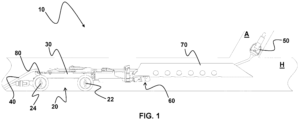
- Fig. 1 shows a side view of a particularly preferred device for sewer pipe inspection and/or renovation of a connecting line branching off from a main sewer with a lowered guide element.
- Fig. 1 a particularly preferred device 10 for sewer pipe inspection and/or rehabilitation of a connecting line A branching off from a main sewer H, with a carriage 20 which has a front axle 22 and a rear axle 24.
- a lateral inspection and/or rehabilitation system is provided on the carriage 20, which has an adapter 30 detachably connected to the carriage 20.
- An inspection and/or rehabilitation unit 50 which is displaceably mounted by means of a push rod 40 and which forms the satellite unit is provided in the adapter 30. The advance of the satellite unit can be done manually or preferably by motor.
- a guide element 70 is provided which is pivotably mounted on the adapter 30 by means of a first joint 60 and is designed to guide the inspection and/or rehabilitation unit from a main channel into a connecting line.
- the first joint 60 which is designed as a rotary-tilting joint, and thus also the guide element 70 are arranged in the area in front of the front axle 22 of the carriage 20.
- the adapter 30 also has a second joint 80 on a section opposite the guide element 70, which allows the adapter 30 to pivot about an axis arranged parallel to the wheel axles relative to the carriage 20.
- the second joint 80 which causes the adapter 30 to pivot relative to the carriage 20, is arranged in the area of the rear axle 24 of the carriage 20, so that a compact unit 10 is realized.
- Fig. 2 shows the Fig. 1 known device with a fully raised and at the same time angled guide element 70 in a main channel H. It can be clearly seen that even the free end of a short guide element 70 can be guided to a considerable height by the interaction of the first joint 60 with the second joint 80 while maintaining a low center of gravity. This enables the advantageous introduction of the inspection and/or rehabilitation unit 50, designed as a milling cutter in the example shown, into the connecting line A branching off from the main channel H.
- Fig. 2 It can be seen that the drive which causes the adapter 30 to pivot relative to the carriage 20 is specifically designed as a spindle drive, wherein the guide element 70 is a guide tube.
Landscapes
- Engineering & Computer Science (AREA)
- General Engineering & Computer Science (AREA)
- Chemical & Material Sciences (AREA)
- Combustion & Propulsion (AREA)
- Mechanical Engineering (AREA)
- Health & Medical Sciences (AREA)
- Life Sciences & Earth Sciences (AREA)
- Hydrology & Water Resources (AREA)
- Public Health (AREA)
- Water Supply & Treatment (AREA)
- Sewage (AREA)
Description
- Die Erfindung betrifft eine Vorrichtung zur Kanalrohrinspektion und/oder -sanierung einer von einem Hauptkanal abzweigenden Anschlussleitung. Insbesondere betrifft die Erfindung eine Vorrichtung zur Kanalrohrinspektion und/oder -sanierung einer von einem Hauptkanal abzweigenden Anschlussleitung, mit einem Fahrwagen, der eine Vorderachse und eine Hinterachse aufweist, und einem am Fahrwagen angeordneten lateralen Inspektions- und/oder Sanierungssystem, das einen mit dem Fahrwagen lösbar verbundenen Adapter, eine im Adapter mittels eines Schiebestabs verschieblich gelagerte Inspektions- und/oder Sanierungseinheit, und ein am Adapter mittels eines ersten Gelenks verschwenkbar gelagertes, zur Führung der Inspektions- und/oder Sanierungseinheit aus einem Hauptkanal in eine Anschlussleitung eingerichtetes Führungselement aufweist.
- Derartige Vorrichtungen zur Kanalrohrinspektion und/oder -sanierung sind bereits aus offenkundiger Vorbenutzung, insbesondere aber aus der
DE 10 2020 210 713 A1 und derEP 1 070 905 B1 bekannt. Die Vorrichtungen sind regelmäßig modular aufgebaut und weisen ein universell einsetzbares Fahrwagenmodul auf, das mittels eines Adapters, eines im Adapter verschieblich gelagerten Satellitensystems und eines beispielsweise als Rohr ausgebildeten Führungselements zur Inspektion von von einem Hauptkanal abzweigenden Anschlussleitungen an unterschiedliche Rohrdurchmesser des Hauptkanals angepasst werden können. - So wird insbesondere durch Verschwenken des freien Endes unterschiedlich langer Führungselemente erreicht, dass ein mit dem Fahrwagen mitgeführtes Satellitensystem in Anschlussleitungen von Hauptkanälen unterschiedlicher Nennweite von beispielsweise DN150 bis DN 2000 eingeführt werden kann und dort Inspektions- und/oder Sanierungsarbeiten ausgeführt werden können.
- Nachteilig an diesen bekannten Vorrichtungen ist jedoch, dass die Vorrichtung jeweils an die Nennweite des Hauptkanals angepasst werden muss, sodass zwischen verschiedenen Einsatzorten zum Austausch der Führungselemente lange (Um-)Rüstzeiten in Kauf genommen werden müssen. Gleichzeitig ist zu beobachten, dass sich der Durchmesser eines Hauptkanals entlang einer zu inspizierenden oder zu sanierenden Strecke ändern kann, sodass eine Inspektion oder Sanierung nicht in einem Arbeitsschritt möglich ist.
- Darüber hinaus besteht das Problem bei Hauptkanälen mit großer Nennweite, die den Einsatz eines langen Führungselements erfordern, dass die mit einem langen Führungselement ausgestattete Vorrichtung zur Kanalrohrinspektion und/oder -sanierung eine Höhe und/oder eine Länge erreichen kann, die verhindert, dass die Vorrichtung durch den Schacht als Ganzes in den Hauptkanal eingebracht werden kann. Vielmehr muss die Vorrichtung in einem solchen Fall innerhalb des Schachts eingerichtet werden, sodass weiterer Zeitbedarf hinsichtlich der Rüstzeit der Vorrichtung und der Einrichtung von entsprechenden Sicherheitsmaßnahmen zum Betreten des Schachts bestehen.
- Schließlich weisen die bekannten Vorrichtungen den Nachteil auf, dass aufgrund der Verwendung von langen Führungselementen das Problem besteht, dass der Fahrwagen beim Durchführen des Satellitensystem durch das Führungselement zu Kippen und im Rohr zu Verkanten droht.
- Aufgabe der Erfindung ist es daher, eine Vorrichtung zur Kanalrohrinspektion und/oder - sanierung einer von einem Hauptkanal abzweigenden Anschlussleitung zu schaffen, mit der eine Vielzahl von Hauptkanälen unterschiedlichen Durchmessers befahren und davon abzweigende Anschlussleitungen erreicht werden können, ohne dass lange (Um-)Rüstzeiten erforderlich sind oder die Gefahr eines Kippens und Verkanten des Fahrwagens besteht.
- Diese Aufgabe wird erfindungsgemäß durch die Vorrichtung mit den Merkmalen von Anspruch 1 gelöst. Die Unteransprüche geben vorteilhafte Ausgestaltungen der Erfindung wieder.
- Der Grundgedanke der Erfindung besteht darin, zu dem bekannten, ein Verschwenken des freien Endes des Führungselements ermöglichenden ersten Gelenk zusätzlich ein zweites Gelenk vorzusehen, das ein Anheben des Führungselements insgesamt und damit auch ein Anheben des ersten Gelenks ermöglicht, das dadurch weiter in Richtung der Rohrmitte gelangt, um - ohne im Wesentlichen den Schwerpunkt des Gesamtsystems anzuheben - mit dem freien Ende auch Anschlussleitungen in Hauptkanälen mit großem Durchmesser zu erreichen. Dabei ist bevorzugt vorgesehen, dass die beiden Gelenke maximal weit entfernt voneinander angeordnet sind, ohne jedoch die Hauptabmessung des Gesamtsystems zu vergrößern - dieses erfolgt insbesondere dadurch, dass das erste Gelenk vor der Vorderachse des Fahrwagens und das zweite Gelenk im Bereich der Hinterachse des Fahrwagens angeordnet ist. Durch diese Ausgestaltung ist es möglich, die Länge des Führungselements möglichst gering zu halten, zugleich aber auch Anschlussleitungen in Hauptkanälen mit großer Nennweite zu erreichen. Aufgrund der Kompaktheit der erfindungsgemäß ausgestalteten Vorrichtung kann ein niedriger Schwerpunkt verwirklicht werden, wobei auch bei einer geringen Auskragung des Führungselements über die Vorderachse des Fahrwagens hinaus nur geringe Kippmomente auftreten, sodass die Vorrichtung insgesamt eine hohe Standsicherheit aufweist. Dieses ist insbesondere bei eiförmigen Rohrprofilen von Vorteil. Schließlich werden auch sich aus einem Neigen des Führungsrohrs ergebende scharfe Biegeradien des Schiebestabs vermieden, sodass ein Vorschub des Satellitensystems in den Abzweiger leichter verwirklicht werden kann.
- Schließlich ist die erfindungsgemäß ausgestaltete Vorrichtung an Hauptkanäle mit unterschiedlicher Nennweite anpassbar, ohne dass die Vorrichtung umgerüstet werden müsste.
- Erfindungsgemäß wird also eine Vorrichtung zur Kanalrohrinspektion und/oder -sanierung einer von einem Hauptkanal abzweigenden Anschlussleitung vorgeschlagen, wobei die Vorrichtung einen Fahrwagen, der eine Vorderachse und eine Hinterachse besitzt, und ein am Fahrwagen angeordnetes laterales Inspektions- und/oder Sanierungssystem aufweist, das einen mit dem Fahrwagen lösbar verbundenen Adapter, eine im Adapter mittels eines Schiebestabs verschieblich gelagerte Inspektions- und/oder Sanierungseinheit, und ein am Adapter mittels eines ersten Gelenks verschwenkbar gelagertes, zur Führung der Inspektions- und/oder Sanierungseinheit aus einem Hauptkanal in eine Anschlussleitung eingerichtetes Führungselement aufweist, wobei der Adapter an einem dem Führungselement gegenüberliegenden Abschnitt mittels eines zweiten Gelenks um eine parallel zu den Radachsen angeordnete Achse relativ zum Fahrwagen verschwenkbar gelagert ist, wobei das ein Verschwenken des Führungselements gegenüber dem Adapter bewirkende erste Gelenk im Bereich vor der Vorderachse des Fahrwagens und das ein Verschwenken des Adapters gegenüber dem Fahrwagen bewirkende zweite Gelenk im Bereich der Hinterachse des Fahrwagens angeordnet ist.
- Bei dem zweiten Gelenk handelt es sich also um ein einfaches Drehgelenk, das ein Verschwenken des ersten Gelenks auf einem um die Drehachse des zweiten Gelenks gedachten Kreisbogen erlaubt.
- Das ein Verschwenken des Führungselements gegenüber dem Adapter bewirkende erste Gelenk ist erfindungsgemäß im Bereich vor der Vorderachse des Fahrwagens angeordnet und erlaubt primär ein Verschwenken des Führungselements um eine parallel zu den Radachsen ausgerichtete Achse. Besonders bevorzugt ist das erste Gelenk jedoch als Dreh-Kippgelenk ausgebildet, sodass das Führungselement zusätzlich zum Verschwenken auch gedreht werden kann. Gemäß dieser besonders bevorzugten Ausgestaltung ist es nicht nur durch Anheben des freien Endes des Führungselements möglich, Anschlussleitungen oberhalb des Fahrwagens, sondern durch gleichzeitiges Drehen des Führungselements auch seitlich in den Hauptkanal mündende Anschlussleitungen zu erreichen.
- Das ein Verschwenken des Adapters gegenüber dem Fahrwagen bewirkende zweite Gelenk hingegen ist erfindungsgemäß im Bereich der Hinterachse des Fahrwagens angeordnet, sodass sich der Adapter über die Länge des Fahrwagens erstreckt. Insbesondere erstreckt sich das Führungselement nur wenig über die Vorderachse des Fahrwagens, sodass bei gleichzeitigem Verschwenken des Führungselements und des Adapters relativ zum Fahrwagen nur ein geringes Kippmoment resultiert.
- Weiter ist bevorzugt vorgesehen, dass das Verschwenken des Adapters mittels eines Antriebs erfolgt, der zwar auch vom Fahrwagen bereitgehalten werden kann, bevorzugt jedoch als Bestandteil des Adapters selbst ausgebildet ist. Der Antrieb ist dabei besonders bevorzugt als Spindelantrieb ausgebildet, wobei die für den Antrieb erforderliche elektrische Energie durch den Fahrwagen bereitgestellt wird.
- Weiter ist bevorzugt eine die im Adapter verschieblich gelagerte Inspektions- und/oder Sanierungseinheit vorschiebende und zurückziehende Vorschubeinheit vorgesehen, die entweder Bestandteil des Adapters oder als modular am Adapter anzuordnende Einheit ausgebildet ist. Speziell ist vorgesehen, dass die Vorschubeinheit zwischen dem Adapter und dem Führungselement angeordnet ist, wobei Fahrwagen, Adapter, Vorschubeinheit und Führungselement als miteinander verbindbare Module ausgebildet sind, die für den jeweiligen Verwendungszweck unterschiedlich ausgebildet sein können.
- Schließlich ist vorgesehen, dass das Führungselement als Führungsschiene oder als Führungsrohr ausgebildet ist.
- Die Erfindung wird im Folgenden anhand eines in den beigefügten Zeichnungen dargestellten, besonders bevorzugt ausgestalteten Ausführungsbeispiels näher erläutert. Es zeigen:
- Fig. 1
- eine Seitenansicht einer besonders bevorzugt ausgestalteten Vorrichtung zur Kanalrohrinspektion und/oder -sanierung einer von einem Hauptkanal abzweigenden Anschlussleitung mit gesenktem Führungselement; und
- Fig. 2
- eine Seitenansicht der in
Fig. 1 dargestellten Vorrichtung mit vollständig angehobenem Führungselement in einem Rohr. -
Fig. 1 zeigt eine Seitenansicht einer besonders bevorzugt ausgestalteten Vorrichtung zur Kanalrohrinspektion und/oder -sanierung einer von einem Hauptkanal abzweigenden Anschlussleitung mit gesenktem Führungselement. - Insbesondere zeigt
Fig. 1 eine besonders bevorzugt ausgestaltete Vorrichtung 10 zur Kanalrohrinspektion und/oder -sanierung einer von einem Hauptkanal H abzweigenden Anschlussleitung A, mit einem Fahrwagen 20, der eine Vorderachse 22 und eine Hinterachse 24 aufweist. Auf dem Fahrwagen 20 ist ein laterales Inspektions- und/oder Sanierungssystem vorgesehen, das einen mit dem Fahrwagen 20 lösbar verbundenen Adapter 30 aufweist. Im Adapter 30 ist eine mittels eines Schiebestabs 40 verschieblich gelagerte Inspektions- und/oder Sanierungseinheit 50 vorgesehen, die die Satelliteneinheit bildet. Der Vorschub der Satelliteneinheit kann manuell oder bevorzugt motorisch erfolgen. - Weiter ist zu erkennen, dass ein am Adapter 30 mittels eines ersten Gelenks 60 verschwenkbar gelagertes, zur Führung der Inspektions- und/oder Sanierungseinheit aus einem Hauptkanal in eine Anschlussleitung eingerichtetes Führungselement 70 vorgesehen ist. Das erste Gelenk 60, das als Dreh-Kippgelenk ausgebildet ist, und somit auch das Führungselement 70 sind im Bereich vor der Vorderachse 22 des Fahrwagens 20 angeordnet.
- Der Adapter 30 weist weiter auch an einem dem Führungselement 70 gegenüberliegenden Abschnitt ein zweites Gelenk 80 auf, das ein Verschwenken des Adapters 30 um eine parallel zu den Radachsen angeordnete Achse relativ zum Fahrwagen 20 erlaubt. Das ein Verschwenken des Adapters 30 gegenüber dem Fahrwagen 20 bewirkende zweite Gelenk 80 ist im Bereich der Hinterachse 24 des Fahrwagens 20 angeordnet, sodass eine kompakte Einheit 10 verwirklicht wird.
-
Fig. 2 zeigt die ausFig. 1 bekannte Vorrichtung mit vollständig angehobenem und zugleich abgewinkeltem Führungselement 70 in einem Hauptkanal H. Es ist deutlich zu erkennen, dass selbst das freie Ende eines kurzen Führungselements 70 durch Zusammenwirken des ersten Gelenks 60 mit dem zweiten Gelenk 80 bei gleichzeitig niedrigem Schwerpunkt auf eine beachtliche Höhe geführt werden kann. Dieses ermöglicht das vorteilhafte Einführen der im gezeigten Beispiel als Fräser ausgebildeten Inspektions- und/oder Sanierungseinheit 50 in die vom Hauptkanal H abzweigende Anschlussleitung A. - Schließlich ist in
Fig. 2 zu erkennen, dass der ein Verschwenken des Adapters 30 gegenüber dem Fahrwagen 20 bewirkende Antrieb speziell als Spindelantrieb ausgebildet ist, wobei das Führungselement 70 ein Führungsrohr ist.
Claims (5)
- Vorrichtung (10) zur Kanalrohrinspektion und/oder -sanierung einer von einem Hauptkanal abzweigenden Anschlussleitung, mit einem Fahrwagen (20), der eine Vorderachse (22) und eine Hinterachse (24) aufweist, und einem am Fahrwagen (20) angeordneten lateralen Inspektions- und/oder Sanierungssystem, das- einen mit dem Fahrwagen (20) verbundenen Adapter (30),- eine im Adapter (30) mittels eines Schiebestabs (40) verschieblich gelagerte Inspektions- und/oder Sanierungseinheit (50), und- ein am Adapter (30) mittels eines ersten Gelenks (60) verschwenkbar gelagertes, zur Führung der Inspektions- und/oder Sanierungseinheit (50) aus einem Hauptkanal in eine Anschlussleitung eingerichtetes Führungselement (70) aufweist,wobei der Adapter (30) an einem dem Führungselement (70) gegenüberliegenden Abschnitt mittels eines zweiten Gelenks (80) um eine parallel zu den Radachsen angeordnete Achse relativ zum Fahrwagen (20) verschwenkbar gelagert ist, wobei- das ein Verschwenken des Führungselements (70) gegenüber dem Adapter (30) bewirkende erste Gelenk im Bereich vor der Vorderachse (22) des Fahrwagens (20) angeordnet ist,dadurch gekennzeichnet, dass- der Adapter (30) mit dem Fahrwagen (20) lösbar verbunden ist und- das ein Verschwenken des Adapters (30) gegenüber dem Fahrwagen (20) bewirkende zweite Gelenk (80) im Bereich der Hinterachse (24) des Fahrwagens (20) angeordnet ist.
- Vorrichtung (10) nach Anspruch 1, dadurch gekennzeichnet, dass das ein Verschwenken des Führungselements (70) gegenüber dem Adapter (30) bewirkende erste Gelenk (60) als Dreh-Kippgelenk ausgebildet ist.
- Vorrichtung (10) nach einem der vorhergehenden Ansprüche, dadurch gekennzeichnet, dass der Adapter (30) einen ein Verschwenken des Adapters (30) gegenüber dem Fahrwagen (20) bewirkenden Antrieb aufweist.
- Vorrichtung (10) nach Anspruch 3, dadurch gekennzeichnet, dass der Antrieb als Spindelantrieb ausgebildet ist.
- Vorrichtung (10) nach einem der vorhergehenden Ansprüche, dadurch gekennzeichnet, dass das Führungselement (70) als Führungsschiene oder als Führungsrohr ausgebildet ist.
Applications Claiming Priority (1)
| Application Number | Priority Date | Filing Date | Title |
|---|---|---|---|
| DE102022106692.4A DE102022106692A1 (de) | 2022-03-22 | 2022-03-22 | Vorrichtung zur Kanalrohrinspektion und/oder -sanierung einer von einem Hauptkanal abzweigenden Anschlussleitung |
Publications (3)
| Publication Number | Publication Date |
|---|---|
| EP4249788A1 EP4249788A1 (de) | 2023-09-27 |
| EP4249788B1 true EP4249788B1 (de) | 2024-10-23 |
| EP4249788C0 EP4249788C0 (de) | 2024-10-23 |
Family
ID=84901214
Family Applications (1)
| Application Number | Title | Priority Date | Filing Date |
|---|---|---|---|
| EP23150899.5A Active EP4249788B1 (de) | 2022-03-22 | 2023-01-10 | Vorrichtung zur kanalrohrinspektion und/oder -sanierung einer von einem hauptkanal abzweigenden anschlussleitung |
Country Status (2)
| Country | Link |
|---|---|
| EP (1) | EP4249788B1 (de) |
| DE (1) | DE102022106692A1 (de) |
Family Cites Families (3)
| Publication number | Priority date | Publication date | Assignee | Title |
|---|---|---|---|---|
| DE19934241A1 (de) * | 1999-07-21 | 2001-02-08 | Kanaltechnik Geiger & Kunz Gmb | Vorrichtung zum Durchführen von Kanalarbeiten |
| DE202011004376U1 (de) | 2011-03-24 | 2012-06-26 | Ipek International Gmbh | Hebeeinheit für Rohrinspektionssysteme |
| DE102020210713A1 (de) * | 2020-08-24 | 2022-02-24 | Ibak Helmut Hunger Gmbh & Co Kg | Kanalrohr-Inspektionssystem |
-
2022
- 2022-03-22 DE DE102022106692.4A patent/DE102022106692A1/de active Pending
-
2023
- 2023-01-10 EP EP23150899.5A patent/EP4249788B1/de active Active
Also Published As
| Publication number | Publication date |
|---|---|
| EP4249788A1 (de) | 2023-09-27 |
| DE102022106692A1 (de) | 2023-09-28 |
| EP4249788C0 (de) | 2024-10-23 |
Similar Documents
| Publication | Publication Date | Title |
|---|---|---|
| DE102009040200B4 (de) | Transportvorrichtung für ein längliches Objekt | |
| DE10015340C2 (de) | Walzgerüst für Walzstraßen zum Walzen von metallischen Rohren, Stäben oder Drähten | |
| DE102007016822A1 (de) | Gestängekupplung mit Zapfen | |
| EP1679462B1 (de) | Rohrverlegegerät | |
| DE20018561U1 (de) | Ausbruchsventilanordnung | |
| EP2048321A1 (de) | Bohrgerät und Verfahren zum Betreib eines Bohrgeräts | |
| DE10015339A1 (de) | Walzgerüst für Walzstraßen zum Walzen von metallischen Rohren, Stäben oder Drähten | |
| DE3124268A1 (de) | Vorrichtung zur inspektion der innenseiten von kanalrohren | |
| EP4249788B1 (de) | Vorrichtung zur kanalrohrinspektion und/oder -sanierung einer von einem hauptkanal abzweigenden anschlussleitung | |
| EP1956183B1 (de) | Spannkopf für ein Gestängeelement | |
| WO2004106031A1 (de) | Anlage zum aufbereiten von stoffen | |
| WO2011095283A1 (de) | Aufnahmevorrichtung für kraftfahrzeugbaugruppen | |
| DE102021107962A1 (de) | Rohrabschnittsmontagevorrichtung | |
| DE3315698C2 (de) | ||
| EP1616789A1 (de) | Kopfstück für Betankungssysteme | |
| EP2145073A1 (de) | Bohrsystem | |
| DE3100052C2 (de) | "Vorrichtung für die Einführprüfung von Lehrdornen bei Rohren u.dgl." | |
| DE2629168B2 (de) | Schnellkupplung für Rohrleitungen | |
| DE2817017C2 (de) | Horizontalpreßbohrgerät | |
| DE10218174B4 (de) | Erdbohrvorrichtung mit automatischem Gewindeausgleich 2 | |
| EP3734136A1 (de) | Sanierungspacker mit führung | |
| DE102004034638B4 (de) | Biegevorrichtung für Rohre | |
| EP2236734A1 (de) | Antriebseinheit mit Justiereinrichtung | |
| DE29501733U1 (de) | Kugel-Ringrinnenkupplung für die Verbindung des Kupplungskugeltragarms mit der fahrzeugfesten Führungshülse einer Fahrzeuganhängerkupplung | |
| EP1487600A1 (de) | Vorrichtung zum schälen von rohren aus kunststoff |
Legal Events
| Date | Code | Title | Description |
|---|---|---|---|
| PUAI | Public reference made under article 153(3) epc to a published international application that has entered the european phase |
Free format text: ORIGINAL CODE: 0009012 |
|
| STAA | Information on the status of an ep patent application or granted ep patent |
Free format text: STATUS: REQUEST FOR EXAMINATION WAS MADE |
|
| 17P | Request for examination filed |
Effective date: 20230720 |
|
| AK | Designated contracting states |
Kind code of ref document: A1 Designated state(s): AL AT BE BG CH CY CZ DE DK EE ES FI FR GB GR HR HU IE IS IT LI LT LU LV MC ME MK MT NL NO PL PT RO RS SE SI SK SM TR |
|
| GRAP | Despatch of communication of intention to grant a patent |
Free format text: ORIGINAL CODE: EPIDOSNIGR1 |
|
| STAA | Information on the status of an ep patent application or granted ep patent |
Free format text: STATUS: GRANT OF PATENT IS INTENDED |
|
| RIC1 | Information provided on ipc code assigned before grant |
Ipc: E03F 3/06 20060101ALI20240529BHEP Ipc: E03F 7/12 20060101ALI20240529BHEP Ipc: F16L 55/40 20060101ALI20240529BHEP Ipc: F16L 55/26 20060101AFI20240529BHEP |
|
| GRAJ | Information related to disapproval of communication of intention to grant by the applicant or resumption of examination proceedings by the epo deleted |
Free format text: ORIGINAL CODE: EPIDOSDIGR1 |
|
| STAA | Information on the status of an ep patent application or granted ep patent |
Free format text: STATUS: REQUEST FOR EXAMINATION WAS MADE |
|
| GRAP | Despatch of communication of intention to grant a patent |
Free format text: ORIGINAL CODE: EPIDOSNIGR1 |
|
| STAA | Information on the status of an ep patent application or granted ep patent |
Free format text: STATUS: GRANT OF PATENT IS INTENDED |
|
| INTG | Intention to grant announced |
Effective date: 20240618 |
|
| INTC | Intention to grant announced (deleted) | ||
| INTG | Intention to grant announced |
Effective date: 20240715 |
|
| GRAS | Grant fee paid |
Free format text: ORIGINAL CODE: EPIDOSNIGR3 |
|
| GRAA | (expected) grant |
Free format text: ORIGINAL CODE: 0009210 |
|
| STAA | Information on the status of an ep patent application or granted ep patent |
Free format text: STATUS: THE PATENT HAS BEEN GRANTED |
|
| AK | Designated contracting states |
Kind code of ref document: B1 Designated state(s): AL AT BE BG CH CY CZ DE DK EE ES FI FR GB GR HR HU IE IS IT LI LT LU LV MC ME MK MT NL NO PL PT RO RS SE SI SK SM TR |
|
| REG | Reference to a national code |
Ref country code: GB Ref legal event code: FG4D Free format text: NOT ENGLISH |
|
| REG | Reference to a national code |
Ref country code: CH Ref legal event code: EP |
|
| REG | Reference to a national code |
Ref country code: DE Ref legal event code: R096 Ref document number: 502023000221 Country of ref document: DE |
|
| REG | Reference to a national code |
Ref country code: IE Ref legal event code: FG4D Free format text: LANGUAGE OF EP DOCUMENT: GERMAN |
|
| U01 | Request for unitary effect filed |
Effective date: 20241029 |
|
| U07 | Unitary effect registered |
Designated state(s): AT BE BG DE DK EE FI FR IT LT LU LV MT NL PT RO SE SI Effective date: 20241108 |
|
| U20 | Renewal fee for the european patent with unitary effect paid |
Year of fee payment: 3 Effective date: 20241127 |
|
| PG25 | Lapsed in a contracting state [announced via postgrant information from national office to epo] |
Ref country code: IS Free format text: LAPSE BECAUSE OF FAILURE TO SUBMIT A TRANSLATION OF THE DESCRIPTION OR TO PAY THE FEE WITHIN THE PRESCRIBED TIME-LIMIT Effective date: 20250223 Ref country code: HR Free format text: LAPSE BECAUSE OF FAILURE TO SUBMIT A TRANSLATION OF THE DESCRIPTION OR TO PAY THE FEE WITHIN THE PRESCRIBED TIME-LIMIT Effective date: 20241023 |
|
| PG25 | Lapsed in a contracting state [announced via postgrant information from national office to epo] |
Ref country code: ES Free format text: LAPSE BECAUSE OF FAILURE TO SUBMIT A TRANSLATION OF THE DESCRIPTION OR TO PAY THE FEE WITHIN THE PRESCRIBED TIME-LIMIT Effective date: 20241023 |
|
| PG25 | Lapsed in a contracting state [announced via postgrant information from national office to epo] |
Ref country code: NO Free format text: LAPSE BECAUSE OF FAILURE TO SUBMIT A TRANSLATION OF THE DESCRIPTION OR TO PAY THE FEE WITHIN THE PRESCRIBED TIME-LIMIT Effective date: 20250123 |
|
| PG25 | Lapsed in a contracting state [announced via postgrant information from national office to epo] |
Ref country code: GR Free format text: LAPSE BECAUSE OF FAILURE TO SUBMIT A TRANSLATION OF THE DESCRIPTION OR TO PAY THE FEE WITHIN THE PRESCRIBED TIME-LIMIT Effective date: 20250124 |
|
| PG25 | Lapsed in a contracting state [announced via postgrant information from national office to epo] |
Ref country code: PL Free format text: LAPSE BECAUSE OF FAILURE TO SUBMIT A TRANSLATION OF THE DESCRIPTION OR TO PAY THE FEE WITHIN THE PRESCRIBED TIME-LIMIT Effective date: 20241023 |
|
| PG25 | Lapsed in a contracting state [announced via postgrant information from national office to epo] |
Ref country code: RS Free format text: LAPSE BECAUSE OF FAILURE TO SUBMIT A TRANSLATION OF THE DESCRIPTION OR TO PAY THE FEE WITHIN THE PRESCRIBED TIME-LIMIT Effective date: 20250123 |
|
| PG25 | Lapsed in a contracting state [announced via postgrant information from national office to epo] |
Ref country code: SM Free format text: LAPSE BECAUSE OF FAILURE TO SUBMIT A TRANSLATION OF THE DESCRIPTION OR TO PAY THE FEE WITHIN THE PRESCRIBED TIME-LIMIT Effective date: 20241023 |
|
| PG25 | Lapsed in a contracting state [announced via postgrant information from national office to epo] |
Ref country code: SK Free format text: LAPSE BECAUSE OF FAILURE TO SUBMIT A TRANSLATION OF THE DESCRIPTION OR TO PAY THE FEE WITHIN THE PRESCRIBED TIME-LIMIT Effective date: 20241023 |
|
| PG25 | Lapsed in a contracting state [announced via postgrant information from national office to epo] |
Ref country code: CZ Free format text: LAPSE BECAUSE OF FAILURE TO SUBMIT A TRANSLATION OF THE DESCRIPTION OR TO PAY THE FEE WITHIN THE PRESCRIBED TIME-LIMIT Effective date: 20241023 |
|
| PLBE | No opposition filed within time limit |
Free format text: ORIGINAL CODE: 0009261 |
|
| STAA | Information on the status of an ep patent application or granted ep patent |
Free format text: STATUS: NO OPPOSITION FILED WITHIN TIME LIMIT |
|
| PG25 | Lapsed in a contracting state [announced via postgrant information from national office to epo] |
Ref country code: MC Free format text: LAPSE BECAUSE OF FAILURE TO SUBMIT A TRANSLATION OF THE DESCRIPTION OR TO PAY THE FEE WITHIN THE PRESCRIBED TIME-LIMIT Effective date: 20241023 |
|
| 26N | No opposition filed |
Effective date: 20250724 |
|
| U20 | Renewal fee for the european patent with unitary effect paid |
Year of fee payment: 4 Effective date: 20251104 |
|
| PG25 | Lapsed in a contracting state [announced via postgrant information from national office to epo] |
Ref country code: IE Free format text: LAPSE BECAUSE OF NON-PAYMENT OF DUE FEES Effective date: 20250110 |
|
| REG | Reference to a national code |
Ref country code: CH Ref legal event code: U11 Free format text: ST27 STATUS EVENT CODE: U-0-0-U10-U11 (AS PROVIDED BY THE NATIONAL OFFICE) Effective date: 20260201 |