EP4249752B1 - Flüssigkeitsförderpumpe und flüssigkeitsförderverfahren - Google Patents
Flüssigkeitsförderpumpe und flüssigkeitsförderverfahren Download PDFInfo
- Publication number
- EP4249752B1 EP4249752B1 EP21894374.4A EP21894374A EP4249752B1 EP 4249752 B1 EP4249752 B1 EP 4249752B1 EP 21894374 A EP21894374 A EP 21894374A EP 4249752 B1 EP4249752 B1 EP 4249752B1
- Authority
- EP
- European Patent Office
- Prior art keywords
- compression
- plunger
- pressure
- liquid feeding
- control unit
- Prior art date
- Legal status (The legal status is an assumption and is not a legal conclusion. Google has not performed a legal analysis and makes no representation as to the accuracy of the status listed.)
- Active
Links
Images






Classifications
-
- F—MECHANICAL ENGINEERING; LIGHTING; HEATING; WEAPONS; BLASTING
- F04—POSITIVE - DISPLACEMENT MACHINES FOR LIQUIDS; PUMPS FOR LIQUIDS OR ELASTIC FLUIDS
- F04B—POSITIVE-DISPLACEMENT MACHINES FOR LIQUIDS; PUMPS
- F04B13/00—Pumps specially modified to deliver fixed or variable measured quantities
-
- G—PHYSICS
- G01—MEASURING; TESTING
- G01N—INVESTIGATING OR ANALYSING MATERIALS BY DETERMINING THEIR CHEMICAL OR PHYSICAL PROPERTIES
- G01N30/00—Investigating or analysing materials by separation into components using adsorption, absorption or similar phenomena or using ion-exchange, e.g. chromatography or field flow fractionation
- G01N30/02—Column chromatography
- G01N30/26—Conditioning of the fluid carrier; Flow patterns
- G01N30/28—Control of physical parameters of the fluid carrier
- G01N30/32—Control of physical parameters of the fluid carrier of pressure or speed
-
- F—MECHANICAL ENGINEERING; LIGHTING; HEATING; WEAPONS; BLASTING
- F04—POSITIVE - DISPLACEMENT MACHINES FOR LIQUIDS; PUMPS FOR LIQUIDS OR ELASTIC FLUIDS
- F04B—POSITIVE-DISPLACEMENT MACHINES FOR LIQUIDS; PUMPS
- F04B11/00—Equalisation of pulses, e.g. by use of air vessels; Counteracting cavitation
- F04B11/0041—Equalisation of pulses, e.g. by use of air vessels; Counteracting cavitation by piston speed control
-
- F—MECHANICAL ENGINEERING; LIGHTING; HEATING; WEAPONS; BLASTING
- F04—POSITIVE - DISPLACEMENT MACHINES FOR LIQUIDS; PUMPS FOR LIQUIDS OR ELASTIC FLUIDS
- F04B—POSITIVE-DISPLACEMENT MACHINES FOR LIQUIDS; PUMPS
- F04B11/00—Equalisation of pulses, e.g. by use of air vessels; Counteracting cavitation
- F04B11/005—Equalisation of pulses, e.g. by use of air vessels; Counteracting cavitation using two or more pumping pistons
-
- F—MECHANICAL ENGINEERING; LIGHTING; HEATING; WEAPONS; BLASTING
- F04—POSITIVE - DISPLACEMENT MACHINES FOR LIQUIDS; PUMPS FOR LIQUIDS OR ELASTIC FLUIDS
- F04B—POSITIVE-DISPLACEMENT MACHINES FOR LIQUIDS; PUMPS
- F04B23/00—Pumping installations or systems
- F04B23/04—Combinations of two or more pumps
- F04B23/06—Combinations of two or more pumps the pumps being all of reciprocating positive-displacement type
-
- F—MECHANICAL ENGINEERING; LIGHTING; HEATING; WEAPONS; BLASTING
- F04—POSITIVE - DISPLACEMENT MACHINES FOR LIQUIDS; PUMPS FOR LIQUIDS OR ELASTIC FLUIDS
- F04B—POSITIVE-DISPLACEMENT MACHINES FOR LIQUIDS; PUMPS
- F04B49/00—Control, e.g. of pump delivery, or pump pressure of, or safety measures for, machines, pumps, or pumping installations, not otherwise provided for, or of interest apart from, groups F04B1/00 - F04B47/00
- F04B49/06—Control using electricity
-
- F—MECHANICAL ENGINEERING; LIGHTING; HEATING; WEAPONS; BLASTING
- F04—POSITIVE - DISPLACEMENT MACHINES FOR LIQUIDS; PUMPS FOR LIQUIDS OR ELASTIC FLUIDS
- F04B—POSITIVE-DISPLACEMENT MACHINES FOR LIQUIDS; PUMPS
- F04B49/00—Control, e.g. of pump delivery, or pump pressure of, or safety measures for, machines, pumps, or pumping installations, not otherwise provided for, or of interest apart from, groups F04B1/00 - F04B47/00
- F04B49/06—Control using electricity
- F04B49/065—Control using electricity and making use of computers
-
- F—MECHANICAL ENGINEERING; LIGHTING; HEATING; WEAPONS; BLASTING
- F04—POSITIVE - DISPLACEMENT MACHINES FOR LIQUIDS; PUMPS FOR LIQUIDS OR ELASTIC FLUIDS
- F04B—POSITIVE-DISPLACEMENT MACHINES FOR LIQUIDS; PUMPS
- F04B51/00—Testing machines, pumps, or pumping installations
-
- F—MECHANICAL ENGINEERING; LIGHTING; HEATING; WEAPONS; BLASTING
- F04—POSITIVE - DISPLACEMENT MACHINES FOR LIQUIDS; PUMPS FOR LIQUIDS OR ELASTIC FLUIDS
- F04B—POSITIVE-DISPLACEMENT MACHINES FOR LIQUIDS; PUMPS
- F04B2201/00—Pump parameters
- F04B2201/02—Piston parameters
- F04B2201/0201—Position of the piston
-
- F—MECHANICAL ENGINEERING; LIGHTING; HEATING; WEAPONS; BLASTING
- F04—POSITIVE - DISPLACEMENT MACHINES FOR LIQUIDS; PUMPS FOR LIQUIDS OR ELASTIC FLUIDS
- F04B—POSITIVE-DISPLACEMENT MACHINES FOR LIQUIDS; PUMPS
- F04B2205/00—Fluid parameters
- F04B2205/05—Pressure after the pump outlet
-
- G—PHYSICS
- G01—MEASURING; TESTING
- G01N—INVESTIGATING OR ANALYSING MATERIALS BY DETERMINING THEIR CHEMICAL OR PHYSICAL PROPERTIES
- G01N30/00—Investigating or analysing materials by separation into components using adsorption, absorption or similar phenomena or using ion-exchange, e.g. chromatography or field flow fractionation
- G01N30/02—Column chromatography
- G01N30/26—Conditioning of the fluid carrier; Flow patterns
- G01N30/28—Control of physical parameters of the fluid carrier
- G01N30/32—Control of physical parameters of the fluid carrier of pressure or speed
- G01N2030/326—Control of physical parameters of the fluid carrier of pressure or speed pumps
Definitions
- the present disclosure relates to a liquid feeding pump and a liquid feeding method.
- a solvent to be used is different according to a type of sample which is a measurement target and it is necessary to exchange a solvent in a liquid feeding pump before each analysis.
- a solvent to be used is different according to a type of sample which is a measurement target and it is necessary to exchange a solvent in a liquid feeding pump before each analysis.
- To perform the exchange of the solvent in a short time it is effective to reduce a pump volume.
- a liquid feeding pump used for a liquid chromatograph has a configuration in which two plunger pumps are connected in series.
- a plunger pump located upstream sucks, compresses, and discharges a solvent. Since a constant flow rate cannot be fed only with the first plunger pump, another plunger pump (a second plunger pump) is connected downstream.
- the second plunger pump performs an operation of counteracting a pulsating flow of the first plunger pump (discharging a solvent when the first plunger pump sucks and compresses the solvent), and thus the liquid feeding pump can feed a constant flow rate.
- PTL 1 discloses a liquid feeding pump that controls an operation of the first plunger pump by providing a pressure sensor measuring a pressure of a solvent in the first plunger pump and a pressure sensor measuring a pressure of a solvent discharged by the second plunger pump, and by comparing values measured by the pressure sensors in a compression process.
- PTL 2 discloses a liquid feeding pump that has a configuration in which the first and second plunger pumps are connected in series and a pressure sensor is provided only downstream from the second plunger pump.
- PTL 3 discloses a liquid feeding pump that corrects and controls a flow rate from a compression volume in a compression process and a history of a pressure while the compression is completed (compression pressure).
- a further liquid pump is known from US8182680 .
- the pressure sensor is provided only on the second plunger pump side, and thus an increase in the pump volume can be said to be suppressed.
- the present invention provides a technology capable of reducing a volume of a liquid feeding pump and enabling liquid feeding with little pulsation.
- the liquid feeding pump according to the present disclosure can reduce a volume of a liquid feeding pump and enables liquid feeding with little pulsation.
- the other problems, configurations, and advantageous effects are apparent from description of the following embodiments.
- Fig. 1 is a schematic view illustrating a configuration of a liquid chromatograph 100 including a liquid feeding pump 1 according to a first embodiment.
- the liquid chromatograph 100 includes the liquid feeding pump 1, an injector 2 introducing a sample into the liquid chromatograph 100, a separation column 3, a detector 4, and a waste liquid container 5. Since the injector 2, the separation column 3, the detector 4, and the waste liquid container 5 can generally be used for liquid chromatographs, detailed configurations will not be described separately in the embodiment.
- the controller 10 gives an instruction value to the motor driver 210 and the electronic valve driver 410 based on the discharge pressure measured by the pressure sensor 110 and a predetermined operation sequence to operate the motor driver 210 and the electronic valve driver 410.
- the controller 10 gives an instruction value to the purge valve driver 310 based on the predetermined operation sequence to operate the purge valve driver 310.
- the first plunger pump 101 includes a first pump head 111 in which a first pressurization chamber 11, a first plunger 21, a first suction passage 31, a first discharge passage 41, a first check valve 51, a second check valve 52, a first seal 61, and a bearing 71 are formed.
- the first check valve 51 is disposed on a flow passage of the first suction passage 31 and the second check valve 52 is disposed on a flow passage of the first discharge passage 41, and thus a flow direction of a solvent liquid is limited.
- the first plunger 21 (a pressurization member) is held to be slidable inside the first plunger pump 101 by the bearing 71.
- the first seal 61 prevents liquid leakage from the first pressurization chamber 11.
- the second plunger pump 102 includes a second pump head 112 in which a second pressurization chamber 12, a second plunger 22, a second suction passage 32, a second discharge passage 42, a second seal 62, and a bearing 72 are formed.
- the second check valve 52 and the second suction passage 32 are connected by the connection flow passage 103. That is, the first plunger pump 101 and the second plunger pump 102 are disposed in series and the first plunger pump 101 is installed upstream.
- the second plunger 22 (a pressurization member) is held to be slidable inside the second plunger pump 102 by the bearing 72.
- the second seal 62 prevents liquid leakage from the second pressurization chamber 12.
- a “lower limit point” indicates a position at which a plunger descends most in a range that the plunger can move inside a pressurization chamber.
- an “upper limit point” indicates a position at which a plunger ascends most in a range that the plunger can move inside a pressurization chamber.
- the “ascending” of the plunger indicates a motion in a direction in which a solvent in the pressurization chamber is compressed or discharged (a motion in the right direction in Fig. 1 ) and the “descending” of the plunger indicates a motion in a direction in which a solvent in the pressurization chamber is sucked (a motion in the left direction in Fig. 1 ).
- a reciprocation motion of the first plunger 21 is controlled by a first electric motor 211, a deceleration device 221, and a straight motion device 231. More specifically, the motor driver 210 supplies driving power to the first electric motor 211 to rotate the first electric motor 211 based on an instruction value of the controller 10. The rotation of the first electric motor 211 is decelerated by the deceleration device 221 and is converted into a straight motion by the straight motion device 231, and thus the first plunger 21 performs a reciprocation motion.
- a reciprocation motion of the second plunger 22 is controlled by a second electric motor 212, a deceleration device 222, and a straight motion device 232. More specifically, the motor driver 210 supplies driving power to the second electric motor 212 to rotate the second electric motor 212 based on an instruction value of the controller 10. The rotation of the second electric motor 212 is decelerated by the deceleration device 222 and is converted into a straight motion by the straight motion device 232, and thus the second plunger 22 performs a reciprocation motion.
- the electronic valve driver 410 supplies driving power to the first electronic valve 81 and the second electronic valve 82 based on an instruction value of the controller 10.
- a solvent container that contains a first solvent 511 and a solvent container that contains a second solvent 512 are installed outside of the liquid feeding pump 1.
- the first solvent 511 or the second solvent 512 can be fed to the liquid feeding pump 1 by opening or closing the first electronic valve 81 and the second electronic valve 82 and driving the first plunger pump 101 and the second plunger pump 102 (the first plunger 21 and the second plunger 22).
- the first plunger pump 101 sucks a solvent
- one of the first electronic valve 81 and the second electronic valve 82 enters an opened state and the other valve enters a closed state, and one of the first solvent 511 and the second solvent 512 is sucked.
- the sucked solvent passes through the first check valve 51 and the first suction passage 31 to be sucked to the first pressurization chamber 11.
- the solvent sucked inside the first pressurization chamber 11 is compressed as the first plunger 21 ascends.
- the solvent When the solvent is compressed and an internal pressure of the first pressurization chamber 11 is greater than the internal pressure of the second pressurization chamber 12, the solvent flows in the first discharge passage 41, the second check valve 52, the connection flow passage 103, and the second suction passage 32 and is discharged from the second discharge passage 42.
- the injector 2 injects a sample which is an analysis target into the solvent discharged from the liquid feeding pump 1.
- the solvent into which the sample is injected is introduced into the separation column 3 and is separated into components. Thereafter, the detector 4 detects absorbance, fluorescence intensity, a refractive index, or the like according to the sample components.
- the separation column 3 is filled with fine particles, and thus a load pressure of tens of megapascals to hundred megapascals or more is generated in the liquid feeding pump 1 due to fluid resistance when the solvent flows in gaps of the fine particles. Magnitude of the load pressure differs depending on a diameter of the separation column 3 and a passage flow rate.
- the first electronic valve 81 When analysis using the first solvent 511 is switched to analysis using the second solvent 512, the first electronic valve 81 is switched from an opened state to a closed state before the analysis using the second solvent 512, and then the second electronic valve 82 is switched from the closed state to the opened state. Accordingly, the inside (the first check valve 51, the first suction passage 31, the first pressurization chamber 11, the first discharge passage 41, the second check valve 52, the connection flow passage 103, the second suction passage 32, the second pressurization chamber 12, the second discharge passage 42, the pressure sensor 110, the purge valve 311, and pipe lines connecting therebetween) of the liquid feeding pump 1, the injector 2, the separation column 3, and the detector 4, and the insides of pipe lines connecting therebetween are exchanged from the first solvent 511 to the second solvent 512.
- the insides of pipe lines connecting therebetween are exchanged from the first solvent 511 to the second solvent 512.
- the first plunger 21 and the second plunger 22 operate together using a lower limit point as a reference.
- the controller 10 actually outputs instruction values to the motor driver 210, the speed of the first plunger 21 and the speed of the second plunger 22 are controlled by driving the first electric motor 211, the second electric motor 212, and the like according to the output values.
- the controller 10 directly controls operations of the first plunger 21 and the second plunger 22 in some descriptions.
- Fig. 3 is a graph illustrating a method of controlling a speed of the first plunger 21 and a speed of the second plunger 22 at the time of normal liquid feeding.
- Fig. 3 illustrates only an operation corresponding to one period.
- the horizontal axis represents a time and the vertical axis represents a displacement of the first plunger 21, a displacement of the second plunger 22, a speed of the first plunger 21, a speed of the second plunger 22, and a pressure in sequence from the top.
- the speed of the first plunger 21 and the speed of the second plunger 22 are set to be positive at the time of ascending of the plungers and negative at the time of descending of the plungers.
- a discharge pressure measured by the pressure sensor 110 is indicated by a solid line and a pressure P11 of the solvent inside the first pressurization chamber 11 is indicated by a dotted line.
- the discharge pressure can be measured by the pressure sensor 110, but there is no mechanism for measuring the pressure P11 of the solvent inside the first pressurization chamber 11.
- the controller 10 descends the first plunger 21 at a negative speed until the lower limit point (see Fig. 2 ) and ascends the second plunger 22 at a constant positive speed from the lower limit point.
- the controller 10 temporarily stops the first plunger 21 (a speed of 0).
- a discharge pressure in the section a is constant.
- the pressure P11 of the solvent inside the first pressurization chamber 11 decreases until a pressure less than the atmospheric pressure and subsequently becomes constant.
- the first plunger 21 stops the pressure becomes the atmospheric pressure.
- the controller 10 ascends the first plunger 21.
- the first plunger 21 is first ascended while the speed is increased, and then the speed is caused to be a constant speed.
- the controller 10 continuously ascends the second plunger 22 at a constant positive speed as in the section a.
- a discharge pressure in the section b1 is constant.
- the solvent is compressed as first plunger 21 ascends, and the pressure P11 of the solvent inside the first pressurization chamber 11 increases.
- the discharge pressure is substantially constant on the whole (except for a pulsation), but the discharge pressure is increased (rises to the right) over time.
- the first plunger 21 may stop (misjudgment of the completion of the compression) despite no sufficient increase in the pressure P11 of the solvent inside the first pressurization chamber 11. Thereafter, when the first plunger 21 ascends and the second plunger 22 descends at the time of start of the section c, the discharge pressure decreases to the pressure inside the first pressurization chamber 11 and a large decrease in pressure occurs.
- a pressure pulsation so-called injection shock
- the discharge pressure increases (rises to the right) on the whole (except for a pulsation), and the discharge pressure is substantially constant in some cases and decreases (falls to the right) in some cases.
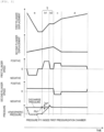
- the compression determination is not performed until a predicted pressure inside the first pressurization chamber 11 becomes a pressure lower by ⁇ PA than a discharge pressure Pb1 immediately before start of the compression (at the time of start of the compression).
- the determination of the compression is started after the pressure is exceeded.
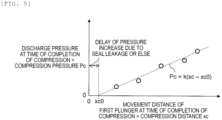
- Expression (1) is based on the following Expression (2) expressing a relationship between the compression distance xc and the compression pressure Pc, as illustrated in Fig. 5 .
- Pc k xc ⁇ xc 0
- the rate of change k may be obtained by storing a history obtained by feeding the liquid at various pressures before the current period in the controller 10 and linearly approximating the relationship between the compression distance xc and the compression pressure Pc from the history. Accordingly, the rate of change k can be calculated more accurately.
- xc0 is obtained automatically at the time of linear approximation and a change in delay of the increase in the pressure which is a cause of xc0 over time can be followed.
- a pressure of the solvent inside the first pressurization chamber 11 at the time of completion of the compression is estimated to be a pressure Pb1 (a current discharge pressure) at the time of start of the compression
- a displacement xA of the first plunger 21 when the pressure is lower by ⁇ PA than that pressure can be expressed as in the following Expression (3).
- xA n Pb 1 n ⁇ ⁇ PA / k n + xc 0
- the displacement xA of the first plunger 21 can be a displacement shorter by a predetermined distance than a displacement of the first plunger 21 predicted at the time of completion of the compression.
- the controller 10 determines a section in which the completion of the compression is not determined (a non-determination section) and a section in which the completion of the compression is determined (a determination section) by using the displacement xA of the first plunger 21 obtained with Expression (3) as a boundary. Accordingly, the controller 10 does not determine whether the compression is completed regardless of presence of a pulsation until the displacement of the first plunger 21 becomes xA.
- the controller 10 starts determining whether the compression is completed when the displacement of the first plunger 21 exceeds xA.
- Fig. 7 is a graph illustrating a method of controlling the first plunger 21 according to a modification example of the first embodiment.
- the first plunger 21 stops in the section b2 after the compression is completed.
- the first plunger 21 is minutely ascended in the section b2.
- the controller 10 decreases a speed of the first plunger 21 and continues the compression after the compression is completed. Accordingly, as illustrated in an upper part of the graphs of Fig. 7 , a decrease (a pulsation) in the pressure at the time of start of the section c can be small.
- the scheme according to the modification example can also be applied to the following embodiment.
- the rate of change k in the pressure of the solvent is calculated based on the compression pressure Pc at the time of completion of the compression in a past period and the compression distance xc of the first plunger 21 in the compression process (the section b) for the solvent by the first plunger 21, the displacement xA (a predetermined distance shorter than a predicted compression distance) of the first plunger 21 when the pressure of the solvent inside the first pressurization chamber 11 is lower by ⁇ PA than the discharge pressure Pb1 is calculated based on the rate of change k in the pressure and the discharge pressure Pb1 (the current discharge pressure) at the time of start of the compression, and a period in which the completion of the compression is judged (when the compression by the first plunger 21 is completed) is determined based on the displacement xA.
- the liquid feeding pump 1 may include only one pressure sensor 110 (the second plunger pump 102 located downstream) to estimate a pressure inside the first pressurization chamber 11 of the first plunger pump 101 by Expression (1). Accordingly, since a pump volume is less than when two pressure sensors are used, the solvent can be exchanged quickly. Since the number of pressure sensors is only one, cost of the device can be reduced more than when two pressure sensors are installed. Since the number of pressure sensors is only one, it is not necessary to adjust a solid difference in the pressure sensor and production efficiency can be improved.
- the detection of the pressure pulsation due to over-compression and the stopping of the compression by the first plunger 21 have been described. Accordingly, in a second embodiment, a method of decreasing a pressure pulsation associated with determination of compression by completing the compression with a prediction value of a compression distance of the first plunger 21 will be proposed.
- Fig. 8 is a graph illustrating a method of determining completion of compression according to a second embodiment.
- the controller 10 obtains a rate of change k(n) in a pressure of a solvent in Expression (1), estimates a compression pressure as the discharge pressure Pb1 at the time of start of the compression, and calculates a displacement xc' (a prediction value of a compression distance) of the first plunger 21 stopping the compression by the following Expression (4).
- xc ′ n Pb 1 n / k n + xc 0
- completion of compression is determined on the assumption that a pulsation arises at the time of compression.
- the completion of the compression is determined when there is no pulsation until the displacement of the first plunger 21 becomes xc'. Accordingly, a pulsation at the time of completion of compression can be further decreased.
- the controller 10 can determine that the compression is completed as in the first embodiment.
- the pressure at the time of completion of the compression is set to the discharge pressure Pb1.
- the pressure at the time of completion of the compression may be predicted according to a change in the discharge pressure.
- the displacement xc' can be calculated more accurately.
- Expression (4) may be frequently calculated for the current pressure and the displacement xc' may be frequently updated.
- the displacement xc' can be calculated further accurately and a pulsation can be decreased as a result.
- the rate of change k in the pressure is calculated based on the compression pressure Pc at the time of completion of the compression in a past period and the compression distance xc of the first plunger 21 in the compression process (the section b) for the solvent by the first plunger 21, the displacement xc' (the compression distance) of the first plunger 21 at the time of completion of the compression is predicted based on the rate of change k in the pressure and the discharge pressure Pb1 (the current discharge pressure) at the time of start of the compression, and the compression of the solvent is completed and the compression is stopped when the displacement becomes xc' (the predicted compression distance) of the first plunger 21 (when the first plunger 21 completes the compression is determined based on the displacement xc'). Accordingly, the pressure pulsation can be decreased. As described in the first embodiment, misjudgment of the completion of the compression due to disturbance is not made.
- the pressure pulsation due to over-compression is detected within a determination period of the compression of the compression and the compression by the first plunger 21 is stopped.
- the compression by the first plunger 21 is stopped when a prediction value of the compression distance is obtained.
- a technology for stopping the compression immediately before a prediction value of a compression distance when a flow rate of a liquid feeding pump becomes 0 will be proposed.
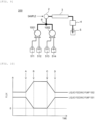
- the liquid chromatograph 200 has a configuration of a so-called high-pressure gradient in which two sets of the liquid feeding pumps are connected in parallel.
- the liquid feeding pumps 1001 and 1002 feed other solvents (the liquid feeding pump 1001 feeds solvents 511 and 512 and the liquid feeding pump 1002 feeds solvents 513 and 514), and the solvents are mixed downstream from a junction 6 and fed to the separation column 3.
- Each of flow ratees of the liquid feeding pumps 1001 and 1002 is appropriately set according to an analysis item.
- ⁇ PD is a difference between an estimation value of the compression pressure and a pressure at which the compression is stopped.
- ⁇ PD can be determined by an experiment carried out in advance and can be set to, for example, a value of 5% to 10% of the discharge pressure Pb1.
- Pb1- ⁇ PD As a value of Pb1- ⁇ PD is closer to a value of the discharge pressure Pb1, a pulsation of a timing (the time C) at which the liquid feeding is resumed can be decreased.
- the pressure at the time of completion of the compression is set to the discharge pressure Pb1 at the time of start of the compression.
- the pressure is a pressure in the section (the section a) before the start of the compression, that is, a pressure while the controller 10 does not monitor a pulsation of a discharge pressure
- the control can be implemented by a controller of lower cost.
- the discharge pressure Pb1 the pressure at the time of completion of the compression may be predicted according to a change in the discharge pressure.
- the displacement xD can be calculated more accurately.
- Expression (5) may be frequently calculated for the current pressure and the displacement xD may be frequently updated.
- the displacement xD can be calculated further accurately and a pulsation can be decreased as a result.
- the rate of change k in the pressure is calculated based on the compression pressure Pc at the time of completion of the compression in a past period before the flow rate is 0 and the compression distance xc of the first plunger 21, the displacement xD (a predetermined distance shorter than predicted compression distance) of the first plunger 21 while the pressure of the solvent inside the first pressurization chamber 11 is lower by ⁇ PD than the discharge pressure Pb1 based on the rate of change k in the pressure and the discharge pressure Pb1 (the current discharge pressure) at the time of start of the compression, and the compression of the solvent is completed (stopped) when the displacement becomes xD of the first plunger 21 (when the first plunger 21 completes the compression is determined based on the displacement xD). Accordingly, a pulsation when the liquid feeding is resumed can be decreased.
- the present disclosure is not limited to the above-described embodiments and includes various modification examples.
- the above-described embodiments have been described in detail to facilitate description of the present disclosure and all the above-described configurations may not be included.
- a part of a certain embodiment can be exchanged with an exemplary configuration of another embodiment.
- a configuration of another embodiment may be added.
- part of other embodiments may be added, deleted, or exchanged.
Landscapes
- Engineering & Computer Science (AREA)
- Mechanical Engineering (AREA)
- General Engineering & Computer Science (AREA)
- Analytical Chemistry (AREA)
- Physics & Mathematics (AREA)
- Health & Medical Sciences (AREA)
- Life Sciences & Earth Sciences (AREA)
- Chemical & Material Sciences (AREA)
- Biochemistry (AREA)
- General Health & Medical Sciences (AREA)
- General Physics & Mathematics (AREA)
- Immunology (AREA)
- Pathology (AREA)
- Computer Hardware Design (AREA)
- Control Of Positive-Displacement Pumps (AREA)
- Details Of Reciprocating Pumps (AREA)
Claims (24)
- Flüssigkeitsförderpumpe, umfassend:eine erste Kolbenpumpe (101), die einen ersten Kolben (21) umfasst;eine zweite Kolbenpumpe (102), die einen zweiten Kolben (22) umfasst und mit der ersten Kolbenpumpe in Reihe geschaltet ist;einen Drucksensor (110), der stromabwärts von der zweiten Kolbenpumpe (101) angeordnet ist; undeine Steuereinheit (10), die ausgelegt ist, um ein Eingangssignal eines Austrittsdrucks einer Flüssigkeit zu empfangen, der durch den Drucksensor (110) gemessen wurde, und um den Antrieb des ersten Kolbens (21) und den Antrieb des zweiten Kolbens (22) zu steuern, dadurch gekennzeichnet, dass:
die Steuereinheit (10) ausgelegt ist, um eine Druckänderungsrate der Flüssigkeit basierend auf einer früheren Kompressionsstrecke des ersten Kolbens (21), während die Flüssigkeit durch die erste Kolbenpumpe (101) komprimiert wird, und einem Druck, während die Kompression beendet wird, zu berechnen, um eine Kompressionsstrecke des ersten Kolbens (21) basierend auf der Druckänderungsrate und einem aktuellen Austrittsdruck vorherzusagen, und um zu bestimmen, wann die Kompression durch den ersten Kolben (21) beendet ist, basierend auf der vorhergesagten Kompressionsstrecke. - Flüssigkeitsförderpumpe nach Anspruch 1, wobei die Steuereinheit (10) ausgelegt ist, um eine Zeitspanne einzustellen, in der eine Verschiebung des ersten Kolbens (21) eine vorbestimmte Strecke überschreitet, die kürzer ist als die vorhergesagte Kompressionsstrecke, als eine Zeitspanne, in der die Beendigung der Kompression bestimmt wird.
- Flüssigkeitsförderpumpe nach Anspruch 2, wobei in der Zeitspanne, in der die Beendigung der Kompression bestimmt wird, die Steuereinheit (10) ausgelegt ist, um die Kompression zu stoppen, wenn ein Pulsieren des Austrittsdrucks eintritt.
- Flüssigkeitsförderpumpe nach Anspruch 1, wobei die Steuereinheit (10) ausgelegt ist, um die Kompression zu stoppen, wenn die Verschiebung des ersten Kolbens (21) die vorhergesagte Kompressionsstrecke ist.
- Flüssigkeitsförderpumpe nach Anspruch 1, wobei, wenn eine Strömungsrate 0 wird, die Steuereinheit (10) ausgelegt ist, um die Kompression zu stoppen, wenn die Verschiebung des ersten Kolbens (21) eine vorbestimmte Strecke kürzer ist als die vorhergesagte Kompressionsstrecke.
- Flüssigkeitsförderpumpe nach Anspruch 5, wobei die Steuereinheit (10) ausgelegt ist, um die Druckänderungsrate basierend auf der Druckstrecke des ersten Kolbens (21), bevor die Strömungsrate gleich 0 ist, und einem Druck, bei dem die Kompression beendet ist, zu berechnen.
- Flüssigkeitsförderpumpe nach Anspruch 1, wobei die Steuereinheit (10) ausgelegt ist, um den aktuellen Austrittsdruck als Druck der Flüssigkeit im Inneren der ersten Kolbenpumpe (21) zu schätzen, wenn die Kompression beendet ist, und um die Kompressionsstrecke vorherzusagen.
- Flüssigkeitsförderpumpe nach Anspruch 1, wobei die Steuereinheit (10) ausgelegt ist, um den Austrittsdruck als den aktuellen Austrittsdruck einzustellen, während die Kompression gestartet wird.
- Flüssigkeitsförderpumpe nach Anspruch 1, wobei die Steuereinheit (10) ausgelegt ist, um den Austrittsdruck als den aktuellen Austrittsdruck einzustellen, bevor die Kompression gestartet wird.
- Flüssigkeitsförderpumpe nach Anspruch 1, wobei die Steuereinheit (10) ausgelegt ist, um die Vorhersage der Kompressionsstrecke bei jeder Messung des aktuellen Austrittsdrucks zu aktualisieren.
- Flüssigkeitsförderpumpe nach Anspruch 1, wobei die Steuereinheit (10) ausgelegt ist, um den ersten Kolben nur für eine vorbestimmte Zeitspanne zu stoppen, nachdem bestimmt wurde, dass die Kompression beendet ist.
- Flüssigkeitsförderpumpe nach Anspruch 1, wobei die Steuereinheit (10) ausgelegt ist, um eine Geschwindigkeit des ersten Kolbens (21) zu reduzieren und um die Kompression fortzusetzen, nachdem bestimmt wurde, dass die Kompression beendet ist.
- Flüssigkeitsförderverfahren, durchgeführt von einer Steuereinheit, die eine Flüssigkeit steuert, die durch eine Flüssigkeitsförderpumpe gefördert wurde, wobei die Flüssigkeitsförderpumpe eine erste Kolbenpumpe, die einen ersten Kolben umfasst, eine zweite Kolbenpumpe, die einen zweiten Kolben umfasst und mit der ersten Kolbenpumpe in Reihe geschaltet ist, und einen Drucksensor umfasst, der stromabwärts von der zweiten Kolbenpumpe angeordnet ist, und einen Austrittsdruck einer Flüssigkeit der zweiten Kolbenpumpe misst, wobei das Verfahren Folgendes umfasst:Berechnen einer Druckänderungsrate der Flüssigkeit basierend auf einer früheren Kompressionsstrecke des ersten Kolbens, während die Flüssigkeit durch die erste Kolbenpumpe komprimiert wird, und einem Druck, während die Kompression beendet wird, durch die Steuereinheit;Vorhersagen einer Kompressionsstrecke des ersten Kolbens basierend auf der Druckänderungsrate und einem aktuellen Austrittsdruck durch die Steuereinheit; undBestimmen, wann die Kompression durch den ersten Kolben beendet ist, basierend auf der vorhergesagten Kompressionsstrecke durch die Steuereinheit.
- Flüssigkeitsförderverfahren nach Anspruch 13, wobei die Steuereinheit eine Zeitspanne, in der die Verschiebung des ersten Kolbens eine vorbestimmte Strecke überschreitet, die kürzer ist als die vorhergesagte Kompressionsstrecke, als Zeitspanne einstellt, in der die Beendigung der Kompression bestimmt wird.
- Flüssigkeitsförderverfahren nach Anspruch 14, wobei in der Zeitspanne, in der die Beendigung der Kompression bestimmt wird, die Steuereinheit die Kompression stoppt, wenn ein Pulsieren des Austrittsdrucks eintritt.
- Flüssigkeitsförderverfahren nach Anspruch 13, wobei die Steuereinheit die Kompression stoppt, wenn die Verschiebung des ersten Kolbens die vorhergesagte Kompressionsstrecke ist.
- Flüssigkeitsförderverfahren nach Anspruch 13, wobei die Steuereinheit die Kompression stoppt, wenn eine Strömungsrate 0 wird, wenn die Verschiebung des ersten Kolbens eine vorbestimmte Strecke kürzer ist als die vorhergesagte Kompressionsstrecke.
- Flüssigkeitsförderverfahren nach Anspruch 17, wobei die Steuereinheit die Druckänderungsrate basierend auf der Druckstrecke des ersten Kolbens, bevor die Strömungsrate gleich 0 ist, und einem Druck berechnet, wenn die Kompression beendet ist.
- Flüssigkeitsförderverfahren nach Anspruch 13, wobei die Steuereinheit den aktuellen Austrittsdruck als Druck der Flüssigkeit im Inneren der ersten Kolbenpumpe schätzt, wenn die Kompression beendet ist, und die Kompressionsstrecke vorhersagt.
- Flüssigkeitsförderverfahren nach Anspruch 13, wobei die Steuereinheit den Austrittsdruck als den aktuellen Austrittsdruck einstellt, während die Kompression gestartet wird.
- Flüssigkeitsförderverfahren nach Anspruch 13, wobei die Steuereinheit den Austrittsdruck als den aktuellen Austrittsdruck einstellt, bevor die Kompression gestartet wird.
- Flüssigkeitsförderverfahren nach Anspruch 13, wobei die Steuereinheit die Vorhersage der Kompressionsstrecke bei jeder Messung des aktuellen Austrittsdrucks aktualisiert.
- Flüssigkeitsförderverfahren nach Anspruch 13, wobei die Steuereinheit den ersten Kolben nur für eine vorbestimmte Zeitspanne stoppt, nach der bestimmt wird, dass die Kompression beendet ist.
- Flüssigkeitsförderpumpe nach Anspruch 13, wobei die Steuereinheit eine Geschwindigkeit des ersten Kolbens verringert und die Kompression fortsetzt, nachdem bestimmt wird, dass die Kompression beendet ist.
Applications Claiming Priority (2)
| Application Number | Priority Date | Filing Date | Title |
|---|---|---|---|
| JP2020192248A JP7503482B2 (ja) | 2020-11-19 | 2020-11-19 | 送液ポンプ及び送液方法 |
| PCT/JP2021/037736 WO2022107500A1 (ja) | 2020-11-19 | 2021-10-12 | 送液ポンプ及び送液方法 |
Publications (3)
| Publication Number | Publication Date |
|---|---|
| EP4249752A1 EP4249752A1 (de) | 2023-09-27 |
| EP4249752A4 EP4249752A4 (de) | 2024-10-30 |
| EP4249752B1 true EP4249752B1 (de) | 2025-04-09 |
Family
ID=81708928
Family Applications (1)
| Application Number | Title | Priority Date | Filing Date |
|---|---|---|---|
| EP21894374.4A Active EP4249752B1 (de) | 2020-11-19 | 2021-10-12 | Flüssigkeitsförderpumpe und flüssigkeitsförderverfahren |
Country Status (5)
| Country | Link |
|---|---|
| US (1) | US12467908B2 (de) |
| EP (1) | EP4249752B1 (de) |
| JP (1) | JP7503482B2 (de) |
| CN (1) | CN116438377B (de) |
| WO (1) | WO2022107500A1 (de) |
Family Cites Families (15)
| Publication number | Priority date | Publication date | Assignee | Title |
|---|---|---|---|---|
| US4643649A (en) * | 1984-07-20 | 1987-02-17 | The Perkin-Elmer Corporation | Digital control for rapid refill of a liquid chromatograph pump |
| US6932910B2 (en) * | 2002-08-12 | 2005-08-23 | Jeffrey S. Melcher | Method and apparatus for recycling wash chemicals used in powder coating |
| JP4855226B2 (ja) * | 2006-11-24 | 2012-01-18 | シーケーディ株式会社 | 薬液供給システム及び薬液供給制御装置 |
| JP2009013957A (ja) | 2007-07-09 | 2009-01-22 | Hitachi High-Technologies Corp | 送液装置とその制御方法 |
| JP4511578B2 (ja) * | 2007-08-28 | 2010-07-28 | 株式会社日立ハイテクノロジーズ | 送液装置、液体クロマトグラフ、および送液装置の運転方法 |
| EP2055945B8 (de) * | 2007-11-01 | 2017-12-06 | Danfoss Power Solutions Aps | Verfahren zum Betrieb einer Fluid-Arbeitsmaschine |
| JP4934647B2 (ja) | 2008-08-04 | 2012-05-16 | 株式会社日立ハイテクノロジーズ | 液体クロマトグラフ用ポンプ |
| US8182680B2 (en) * | 2009-04-29 | 2012-05-22 | Agilent Technologies, Inc. | Primary piston correction during transfer |
| JP5624825B2 (ja) | 2010-07-29 | 2014-11-12 | 株式会社日立ハイテクノロジーズ | 液体クロマトグラフ用ポンプ、および液体クロマトグラフ |
| CN102269157B (zh) * | 2011-06-08 | 2013-03-20 | 中联重科股份有限公司 | 混凝土泵送设备的压力调节方法、系统及混凝土泵送设备 |
| HK1199851A1 (en) * | 2011-09-21 | 2015-07-24 | Bayer Healthcare Llc | Continuous multi-fluid pump device, drive and actuating system and method |
| EP3660310B1 (de) | 2017-07-28 | 2021-10-20 | Shimadzu Corporation | Flüssigkeitszufuhrvorrichtung |
| CN110809713B (zh) | 2017-10-23 | 2022-06-21 | 株式会社岛津制作所 | 送液装置及流体色谱仪 |
| CN112702982B (zh) * | 2018-06-05 | 2023-12-19 | 卡尔蔡司白内障医疗技术公司 | 眼科显微手术工具、系统和使用方法 |
| JP7188591B2 (ja) * | 2019-06-26 | 2022-12-13 | 株式会社島津製作所 | バイナリポンプ及び液体クロマトグラフ |
-
2020
- 2020-11-19 JP JP2020192248A patent/JP7503482B2/ja active Active
-
2021
- 2021-10-12 WO PCT/JP2021/037736 patent/WO2022107500A1/ja not_active Ceased
- 2021-10-12 US US18/032,717 patent/US12467908B2/en active Active
- 2021-10-12 CN CN202180073839.6A patent/CN116438377B/zh active Active
- 2021-10-12 EP EP21894374.4A patent/EP4249752B1/de active Active
Also Published As
| Publication number | Publication date |
|---|---|
| WO2022107500A1 (ja) | 2022-05-27 |
| EP4249752A4 (de) | 2024-10-30 |
| US20230384271A1 (en) | 2023-11-30 |
| JP2022080997A (ja) | 2022-05-31 |
| CN116438377B (zh) | 2025-12-16 |
| EP4249752A1 (de) | 2023-09-27 |
| US12467908B2 (en) | 2025-11-11 |
| JP7503482B2 (ja) | 2024-06-20 |
| CN116438377A (zh) | 2023-07-14 |
Similar Documents
| Publication | Publication Date | Title |
|---|---|---|
| US8191405B2 (en) | Solvent delivery device and analytical system | |
| US8551423B2 (en) | Liquid supply device using check valve and reactive liquid chromatography system | |
| JP5887412B2 (ja) | 液体クロマトグラフ装置及び送液装置 | |
| JP5155937B2 (ja) | 送液装置および液体クロマトグラフ装置 | |
| US12467908B2 (en) | Liquid feeding pump and liquid feeding method | |
| US12210003B2 (en) | Liquid chromatographic apparatus and air bubble removal method of liquid chromatographic apparatus | |
| JP2013217816A (ja) | 液体クロマトグラフ | |
| US12442363B2 (en) | Liquid feeding pump and liquid feeding method | |
| CN103869030B (zh) | 一种具有串联柱塞泵的液相色谱仪及其控制方法 | |
| EP3933196B1 (de) | Flüssigkeitszuführpumpe und flüssigkeitschromatografvorrichtung | |
| US20250198403A1 (en) | Liquid feeding pump and liquid feeding method | |
| US12546299B2 (en) | Liquid delivery pump | |
| EP3748161A1 (de) | Flüssigchromatograph |
Legal Events
| Date | Code | Title | Description |
|---|---|---|---|
| STAA | Information on the status of an ep patent application or granted ep patent |
Free format text: STATUS: THE INTERNATIONAL PUBLICATION HAS BEEN MADE |
|
| PUAI | Public reference made under article 153(3) epc to a published international application that has entered the european phase |
Free format text: ORIGINAL CODE: 0009012 |
|
| STAA | Information on the status of an ep patent application or granted ep patent |
Free format text: STATUS: REQUEST FOR EXAMINATION WAS MADE |
|
| 17P | Request for examination filed |
Effective date: 20230414 |
|
| AK | Designated contracting states |
Kind code of ref document: A1 Designated state(s): AL AT BE BG CH CY CZ DE DK EE ES FI FR GB GR HR HU IE IS IT LI LT LU LV MC MK MT NL NO PL PT RO RS SE SI SK SM TR |
|
| DAV | Request for validation of the european patent (deleted) | ||
| DAX | Request for extension of the european patent (deleted) | ||
| A4 | Supplementary search report drawn up and despatched |
Effective date: 20240930 |
|
| RIC1 | Information provided on ipc code assigned before grant |
Ipc: F04B 11/00 20060101ALI20240924BHEP Ipc: G01N 30/32 20060101ALI20240924BHEP Ipc: F04B 23/06 20060101ALI20240924BHEP Ipc: F04B 13/00 20060101ALI20240924BHEP Ipc: F04B 49/06 20060101AFI20240924BHEP |
|
| GRAP | Despatch of communication of intention to grant a patent |
Free format text: ORIGINAL CODE: EPIDOSNIGR1 |
|
| STAA | Information on the status of an ep patent application or granted ep patent |
Free format text: STATUS: GRANT OF PATENT IS INTENDED |
|
| RIC1 | Information provided on ipc code assigned before grant |
Ipc: F04B 11/00 20060101ALI20241211BHEP Ipc: G01N 30/32 20060101ALI20241211BHEP Ipc: F04B 23/06 20060101ALI20241211BHEP Ipc: F04B 13/00 20060101ALI20241211BHEP Ipc: F04B 49/06 20060101AFI20241211BHEP |
|
| INTG | Intention to grant announced |
Effective date: 20241223 |
|
| GRAS | Grant fee paid |
Free format text: ORIGINAL CODE: EPIDOSNIGR3 |
|
| GRAA | (expected) grant |
Free format text: ORIGINAL CODE: 0009210 |
|
| STAA | Information on the status of an ep patent application or granted ep patent |
Free format text: STATUS: THE PATENT HAS BEEN GRANTED |
|
| AK | Designated contracting states |
Kind code of ref document: B1 Designated state(s): AL AT BE BG CH CY CZ DE DK EE ES FI FR GB GR HR HU IE IS IT LI LT LU LV MC MK MT NL NO PL PT RO RS SE SI SK SM TR |
|
| REG | Reference to a national code |
Ref country code: GB Ref legal event code: FG4D |
|
| REG | Reference to a national code |
Ref country code: CH Ref legal event code: EP |
|
| REG | Reference to a national code |
Ref country code: DE Ref legal event code: R096 Ref document number: 602021029067 Country of ref document: DE |
|
| REG | Reference to a national code |
Ref country code: IE Ref legal event code: FG4D |
|
| REG | Reference to a national code |
Ref country code: NL Ref legal event code: MP Effective date: 20250409 |
|
| PG25 | Lapsed in a contracting state [announced via postgrant information from national office to epo] |
Ref country code: NL Free format text: LAPSE BECAUSE OF FAILURE TO SUBMIT A TRANSLATION OF THE DESCRIPTION OR TO PAY THE FEE WITHIN THE PRESCRIBED TIME-LIMIT Effective date: 20250409 |
|
| REG | Reference to a national code |
Ref country code: AT Ref legal event code: MK05 Ref document number: 1783718 Country of ref document: AT Kind code of ref document: T Effective date: 20250409 |
|
| PG25 | Lapsed in a contracting state [announced via postgrant information from national office to epo] |
Ref country code: FI Free format text: LAPSE BECAUSE OF FAILURE TO SUBMIT A TRANSLATION OF THE DESCRIPTION OR TO PAY THE FEE WITHIN THE PRESCRIBED TIME-LIMIT Effective date: 20250409 Ref country code: ES Free format text: LAPSE BECAUSE OF FAILURE TO SUBMIT A TRANSLATION OF THE DESCRIPTION OR TO PAY THE FEE WITHIN THE PRESCRIBED TIME-LIMIT Effective date: 20250409 Ref country code: PT Free format text: LAPSE BECAUSE OF FAILURE TO SUBMIT A TRANSLATION OF THE DESCRIPTION OR TO PAY THE FEE WITHIN THE PRESCRIBED TIME-LIMIT Effective date: 20250811 |
|
| REG | Reference to a national code |
Ref country code: LT Ref legal event code: MG9D |
|
| PG25 | Lapsed in a contracting state [announced via postgrant information from national office to epo] |
Ref country code: GR Free format text: LAPSE BECAUSE OF FAILURE TO SUBMIT A TRANSLATION OF THE DESCRIPTION OR TO PAY THE FEE WITHIN THE PRESCRIBED TIME-LIMIT Effective date: 20250710 Ref country code: NO Free format text: LAPSE BECAUSE OF FAILURE TO SUBMIT A TRANSLATION OF THE DESCRIPTION OR TO PAY THE FEE WITHIN THE PRESCRIBED TIME-LIMIT Effective date: 20250709 |
|
| PG25 | Lapsed in a contracting state [announced via postgrant information from national office to epo] |
Ref country code: PL Free format text: LAPSE BECAUSE OF FAILURE TO SUBMIT A TRANSLATION OF THE DESCRIPTION OR TO PAY THE FEE WITHIN THE PRESCRIBED TIME-LIMIT Effective date: 20250409 |
|
| PG25 | Lapsed in a contracting state [announced via postgrant information from national office to epo] |
Ref country code: BG Free format text: LAPSE BECAUSE OF FAILURE TO SUBMIT A TRANSLATION OF THE DESCRIPTION OR TO PAY THE FEE WITHIN THE PRESCRIBED TIME-LIMIT Effective date: 20250409 |
|
| PG25 | Lapsed in a contracting state [announced via postgrant information from national office to epo] |
Ref country code: HR Free format text: LAPSE BECAUSE OF FAILURE TO SUBMIT A TRANSLATION OF THE DESCRIPTION OR TO PAY THE FEE WITHIN THE PRESCRIBED TIME-LIMIT Effective date: 20250409 |
|
| PG25 | Lapsed in a contracting state [announced via postgrant information from national office to epo] |
Ref country code: AT Free format text: LAPSE BECAUSE OF FAILURE TO SUBMIT A TRANSLATION OF THE DESCRIPTION OR TO PAY THE FEE WITHIN THE PRESCRIBED TIME-LIMIT Effective date: 20250409 |
|
| PG25 | Lapsed in a contracting state [announced via postgrant information from national office to epo] |
Ref country code: RS Free format text: LAPSE BECAUSE OF FAILURE TO SUBMIT A TRANSLATION OF THE DESCRIPTION OR TO PAY THE FEE WITHIN THE PRESCRIBED TIME-LIMIT Effective date: 20250709 |
|
| PG25 | Lapsed in a contracting state [announced via postgrant information from national office to epo] |
Ref country code: IS Free format text: LAPSE BECAUSE OF FAILURE TO SUBMIT A TRANSLATION OF THE DESCRIPTION OR TO PAY THE FEE WITHIN THE PRESCRIBED TIME-LIMIT Effective date: 20250809 |
|
| PG25 | Lapsed in a contracting state [announced via postgrant information from national office to epo] |
Ref country code: LV Free format text: LAPSE BECAUSE OF FAILURE TO SUBMIT A TRANSLATION OF THE DESCRIPTION OR TO PAY THE FEE WITHIN THE PRESCRIBED TIME-LIMIT Effective date: 20250409 |
|
| PGFP | Annual fee paid to national office [announced via postgrant information from national office to epo] |
Ref country code: DE Payment date: 20251021 Year of fee payment: 5 |
|
| PGFP | Annual fee paid to national office [announced via postgrant information from national office to epo] |
Ref country code: GB Payment date: 20251020 Year of fee payment: 5 |
|
| REG | Reference to a national code |
Ref country code: DE Ref legal event code: R097 Ref document number: 602021029067 Country of ref document: DE |
|
| PG25 | Lapsed in a contracting state [announced via postgrant information from national office to epo] |
Ref country code: SM Free format text: LAPSE BECAUSE OF FAILURE TO SUBMIT A TRANSLATION OF THE DESCRIPTION OR TO PAY THE FEE WITHIN THE PRESCRIBED TIME-LIMIT Effective date: 20250409 Ref country code: DK Free format text: LAPSE BECAUSE OF FAILURE TO SUBMIT A TRANSLATION OF THE DESCRIPTION OR TO PAY THE FEE WITHIN THE PRESCRIBED TIME-LIMIT Effective date: 20250409 |
|
| PG25 | Lapsed in a contracting state [announced via postgrant information from national office to epo] |
Ref country code: CZ Free format text: LAPSE BECAUSE OF FAILURE TO SUBMIT A TRANSLATION OF THE DESCRIPTION OR TO PAY THE FEE WITHIN THE PRESCRIBED TIME-LIMIT Effective date: 20250409 |
|
| PG25 | Lapsed in a contracting state [announced via postgrant information from national office to epo] |
Ref country code: EE Free format text: LAPSE BECAUSE OF FAILURE TO SUBMIT A TRANSLATION OF THE DESCRIPTION OR TO PAY THE FEE WITHIN THE PRESCRIBED TIME-LIMIT Effective date: 20250409 |
|
| PG25 | Lapsed in a contracting state [announced via postgrant information from national office to epo] |
Ref country code: SK Free format text: LAPSE BECAUSE OF FAILURE TO SUBMIT A TRANSLATION OF THE DESCRIPTION OR TO PAY THE FEE WITHIN THE PRESCRIBED TIME-LIMIT Effective date: 20250409 |
|
| PG25 | Lapsed in a contracting state [announced via postgrant information from national office to epo] |
Ref country code: IT Free format text: LAPSE BECAUSE OF FAILURE TO SUBMIT A TRANSLATION OF THE DESCRIPTION OR TO PAY THE FEE WITHIN THE PRESCRIBED TIME-LIMIT Effective date: 20250409 |
|
| PLBE | No opposition filed within time limit |
Free format text: ORIGINAL CODE: 0009261 |
|
| STAA | Information on the status of an ep patent application or granted ep patent |
Free format text: STATUS: NO OPPOSITION FILED WITHIN TIME LIMIT |
|
| REG | Reference to a national code |
Ref country code: CH Ref legal event code: L10 Free format text: ST27 STATUS EVENT CODE: U-0-0-L10-L00 (AS PROVIDED BY THE NATIONAL OFFICE) Effective date: 20260218 |
|
| PG25 | Lapsed in a contracting state [announced via postgrant information from national office to epo] |
Ref country code: RO Free format text: LAPSE BECAUSE OF FAILURE TO SUBMIT A TRANSLATION OF THE DESCRIPTION OR TO PAY THE FEE WITHIN THE PRESCRIBED TIME-LIMIT Effective date: 20250409 |
|
| 26N | No opposition filed |
Effective date: 20260112 |