EP4249366A1 - Durch den rumpf hindurchgehende leuchte - Google Patents
Durch den rumpf hindurchgehende leuchte Download PDFInfo
- Publication number
- EP4249366A1 EP4249366A1 EP23163172.2A EP23163172A EP4249366A1 EP 4249366 A1 EP4249366 A1 EP 4249366A1 EP 23163172 A EP23163172 A EP 23163172A EP 4249366 A1 EP4249366 A1 EP 4249366A1
- Authority
- EP
- European Patent Office
- Prior art keywords
- hull
- light
- leds
- reflectors
- chamber
- Prior art date
- Legal status (The legal status is an assumption and is not a legal conclusion. Google has not performed a legal analysis and makes no representation as to the accuracy of the status listed.)
- Granted
Links
Images




Classifications
-
- B—PERFORMING OPERATIONS; TRANSPORTING
- B63—SHIPS OR OTHER WATERBORNE VESSELS; RELATED EQUIPMENT
- B63B—SHIPS OR OTHER WATERBORNE VESSELS; EQUIPMENT FOR SHIPPING
- B63B45/00—Arrangements or adaptations of signalling or lighting devices
- B63B45/02—Arrangements or adaptations of signalling or lighting devices the devices being intended to illuminate the way ahead or other areas of environments
-
- F—MECHANICAL ENGINEERING; LIGHTING; HEATING; WEAPONS; BLASTING
- F21—LIGHTING
- F21V—FUNCTIONAL FEATURES OR DETAILS OF LIGHTING DEVICES OR SYSTEMS THEREOF; STRUCTURAL COMBINATIONS OF LIGHTING DEVICES WITH OTHER ARTICLES, NOT OTHERWISE PROVIDED FOR
- F21V11/00—Screens not covered by groups F21V1/00, F21V3/00, F21V7/00 or F21V9/00
- F21V11/02—Screens not covered by groups F21V1/00, F21V3/00, F21V7/00 or F21V9/00 using parallel laminae or strips, e.g. of Venetian-blind type
-
- F—MECHANICAL ENGINEERING; LIGHTING; HEATING; WEAPONS; BLASTING
- F21—LIGHTING
- F21V—FUNCTIONAL FEATURES OR DETAILS OF LIGHTING DEVICES OR SYSTEMS THEREOF; STRUCTURAL COMBINATIONS OF LIGHTING DEVICES WITH OTHER ARTICLES, NOT OTHERWISE PROVIDED FOR
- F21V7/00—Reflectors for light sources
-
- F—MECHANICAL ENGINEERING; LIGHTING; HEATING; WEAPONS; BLASTING
- F21—LIGHTING
- F21V—FUNCTIONAL FEATURES OR DETAILS OF LIGHTING DEVICES OR SYSTEMS THEREOF; STRUCTURAL COMBINATIONS OF LIGHTING DEVICES WITH OTHER ARTICLES, NOT OTHERWISE PROVIDED FOR
- F21V7/00—Reflectors for light sources
- F21V7/0025—Combination of two or more reflectors for a single light source
- F21V7/0033—Combination of two or more reflectors for a single light source with successive reflections from one reflector to the next or following
-
- F—MECHANICAL ENGINEERING; LIGHTING; HEATING; WEAPONS; BLASTING
- F21—LIGHTING
- F21V—FUNCTIONAL FEATURES OR DETAILS OF LIGHTING DEVICES OR SYSTEMS THEREOF; STRUCTURAL COMBINATIONS OF LIGHTING DEVICES WITH OTHER ARTICLES, NOT OTHERWISE PROVIDED FOR
- F21V7/00—Reflectors for light sources
- F21V7/0083—Array of reflectors for a cluster of light sources, e.g. arrangement of multiple light sources in one plane
-
- F—MECHANICAL ENGINEERING; LIGHTING; HEATING; WEAPONS; BLASTING
- F21—LIGHTING
- F21W—INDEXING SCHEME ASSOCIATED WITH SUBCLASSES F21K, F21L, F21S and F21V, RELATING TO USES OR APPLICATIONS OF LIGHTING DEVICES OR SYSTEMS
- F21W2107/00—Use or application of lighting devices on or in particular types of vehicles
- F21W2107/20—Use or application of lighting devices on or in particular types of vehicles for water vehicles
-
- F—MECHANICAL ENGINEERING; LIGHTING; HEATING; WEAPONS; BLASTING
- F21—LIGHTING
- F21Y—INDEXING SCHEME ASSOCIATED WITH SUBCLASSES F21K, F21L, F21S and F21V, RELATING TO THE FORM OR THE KIND OF THE LIGHT SOURCES OR OF THE COLOUR OF THE LIGHT EMITTED
- F21Y2115/00—Light-generating elements of semiconductor light sources
- F21Y2115/10—Light-emitting diodes [LED]
Definitions
- the present invention relates to underwater lighting, particular underwater lighting intended for mounting through the hulls of marine vessels below the water line to illuminate the surrounding water.
- Many marine vessels including boats, ships, and yachts, are provided with underwater exterior lighting in their hull. This lighting acts to illuminate the water around the vessel and can provide a pleasing aesthetic appearance. Underwater lighting can also be useful for pleasure fishing vessels.
- Some underwater lights, particularly smaller lights, are fixed directly to the hull of a marine vessel. Many larger underwater lights are mounted within cofferdams formed in the hull of the vessel.
- Very small underwater lights can be entirely external to a hull and fixed thereto. Slightly larger lights are often mounted through the hull, without a cofferdam.
- such underwater lights have shafts that extend through an aperture formed in the hull and a mounting portion formed at an outer end of the shaft for mounting to the hull, thereby sealing the aperture.
- One or more lights are generally mounted at or near the outer end of the shaft for projecting light outwards from the hull.
- the outer end of through hull lights are generally mounted to be as flat to the outer wall of the hull in order to avoid producing unnecessary drag.
- the port and starboard walls of the hulls of marine vessels are generally sloped away from vertical below the water line to ensure the vessel is suitably hydrodynamic.
- hull underwater lights mounted through a port or starboard wall are generally downwardly oriented.
- Preferably light is directed horizontally outwards from the hull, or perhaps even upwards, towards the surface of the water. This is difficult, if not impossible, with current through hull underwater lights. Presently this can only be achieved by either mounting the lights within the shaft of the light or by having a large and bulky outer portion of the light external to the hull. Neither of these solutions are ideal.
- the present invention provides a through-hull light for a marine vessel, the light comprising:
- the present invention is advantageous in that it provides a simple construction in which a through-hull light can be formed with the light from the through-hull light directed upwards a first fixed angle vertically upwards away from a direction directly outwards from the portion of the hull.
- the first direction when mounted to against a hull the first direction will be generally perpendicular to the portion of hull where the through-hull light is mounted. If the portion of hull is a lower portion of the hull, for example significantly below the waterline, then the first direction will be directed downwards from horizontal.
- the reflectors can then direct the light upwards from the first direction to the second direction, towards or above the horizontal providing an improved illumination.
- the size of the shaft can be minimised, thereby minimising the size of the aperture that needs to be formed in the hull of the marine vessel. Further, the use of reflectors positioned above and below rows of LEDs allows the depth of the body to be minimised, allowing a through-hull light according to the present invention to have a low profile.
- the two or more rows of LEDs When mounted through the hull of a marine vessel the two or more rows of LEDs will be mounted to be horizontal such that the reflectors that are parallel to the to the rows of LEDs and are also mounted to be horizontal.
- Each row of LEDs is mounted to direct light straight out of the chamber in a first direction perpendicular to the flat inner side of the body. This may be achieved in any manner apparent to the person skilled in the art.
- the LEDs will be mounted on a board that is mounted parallel with the flat inner side of the body.
- the board may be immediately adjacent the flat inner side of the body, the board may form the flat inner side of the body, or there may be one or more components positioned between the board and the flat inner side of the body.
- Each reflector is positioned either immediately above or below a row of LEDs.
- the reflectors may be formed in any matter apparent to the person skilled in the art.
- Each reflector positioned immediately above a row of LEDs will be angled in a first orientation to direct light incident upon it from the LEDs immediately below the reflector.
- Each reflector positioned immediately below a row of LEDs will be angled in a second direction to direct light incident upon it from the LEDs immediately below the reflector. That is, as all of the reflectors are formed to direct the light upwards from the first direction to the second direction the reflectors positioned immediately above the row of the LEDs are formed in a different manner to the reflectors positioned immediately below the row of the LEDs.
- the through-hull light comprises a plurality of LEDs in at least two separate horizontal rows. Each row will comprise two or more LEDs. The light may have more than two separate horizontal rows. The number of LEDs and the number of rows provided will be dependent upon the type and power of the LEDs and the required output of the light. The LEDs may all be the same colour and/or the same power. Alternatively, LEDs of two or more colours may be provided and/or LEDs of varying power may be provided.
- the first fixed angle may be any suitable angle that can be achieved through reflection of the light emitted from the plurality of LEDs by the reflectors.
- the first fixed angle may be between 10° and 30°, for example between 10° and 20° or between 20° and 30° or between 10° and 15° or between 15° and 20° or between 20° and 25° or between 25° and 30°. This may be achieved by forming the reflectors to have reflecting faces oriented in any suitable manner. Reflecting faces of the reflectors may be curved, flat, faceted, or formed in any other appropriate manner.
- one or more reflectors may be a separate component that are fixed to the front face of a board on which the LEDs are mounted or otherwise held in an appropriate position within the through-hull light. In some embodiments all the reflectors are separate components. In alternative embodiments one or more of the reflectors may be formed as part of a unitary reflecting component mounted around the rows of LEDs and behind the transparent screen. In embodiments of the invention all of the reflectors may be formed as part of a unitary reflecting component.
- the through-hull light further comprises a light redirecting film is positioned in front of the plurality of LEDs adjacent the transparent screen; wherein the light redirecting film is formed and oriented to divert light away from the second direction to a third direction that is a second fixed angle vertically upwards from the second direction when the light is mounted through the hull of a marine vessel; and the second fixed angle is between 1° and 20°.
- Suitable light directing films will be apparent to the person skilled in the art. Any suitable light redirecting film can be used with the through-hull light of the present invention.
- a light redirecting film may be positioned between the transparent screen and the plurality of LEDs and preferably between the transparent screen and the reflectors.
- a light redirecting film is adjacent the transparent screen and within the chamber i.e. positioned adjacent an inner side of the transparent screen.
- a light redirecting film may be affixed to an outer side of the transparent screen.
- the transparent screen may be integrally formed with a light redirecting film.
- the transparent screen may be formed to redirect light in an appropriate manner.
- the second fixed angle may be any suitable angle that can be achieved using a light redirecting film.
- the second fixed angle may be between 5° and 20°, between 5° and 10°, between 10° and 15°, between 15° and 20°, between 5° and 15°, or between 10° and 20°.
- the through-hull light may have any other component suitable for use in through-hull lights.
- the through-hull light may comprise a heat sink formed in the body or the shaft. It may also comprise suitable drivers for the LED lights.
- each through hull light 1, 1' comprises a body 3 for mounting on the outer surface of a hull 2, having an outer side for facing water 4 and a flat inner side for mounting against the hull 2, and a shaft 5 extending from the inner side of the body 3 for extending through an aperture formed in the hull 2.
- the shafts extend inwards in a direction perpendicular to the section of hull 2 at which the through-hull light 1, 1' is mounted.
- the uppermost through-hull light 1' which is a through-hull light according to the prior art is mounted at a vertical section of hull 2 and so directs light horizontally outwards from the hull. There is no need for any light redirection from this through-hull light 1'.
- the five lower through-hull lights 1 are lights according to the present invention. Each is mounted at a section of hull that is angled away from the vertical and thus, if their light was not redirected would project light in a direction below the horizontal. All five of these through-hull lights 1 are lights according to the present invention and thus their light is redirected to be substantially horizontal. That is, the five lower through-hull lights 1 include light redirection means (discussed below) that act to redirect light so that it is emitted in substantially the same direction as the uppermost through-hull light 1' according to the prior art. In particular, the lowermost light 1 includes light redirecting means to redirect the light through 50°, the lights above that light include redirecting means to redirect the light through 40°, 30°, 20°, and 10° respectively.
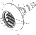
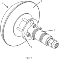
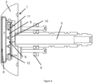
- a first embodiment of a through-hull light 1 according to the present invention is shown in Figures 2 to 4 .
- the light 1 comprises a comprises a body 3 for mounting on the outer surface of a hull 2, having an outer side for facing water and a flat inner side for mounting against the hull 2, and a shaft 5 extending from the inner side of the body 3 for extending through an aperture formed in the hull 2.
- a clamping member 6 for clamping the light in position is also provided.
- a chamber 7 is formed within the body 3.
- a transparent screen 8 is mounted at an outer side of the chamber 7.
- a plurality of LEDs 9 are mounted within the chamber 7 on a front face of a printed circuit board 10. The LEDs 9 are mounted in parallel horizontal rows, each row vertically spaced apart from the others. Each LED 9 is mounted to direct light straight out of the chamber 7 in a first direction perpendicular to a flat inner side of the body 3.
- An upper reflector 11 is positioned immediately above each row of LEDs 9.
- a lower reflector 12 is positioned immediately below each row of LEDs 9.
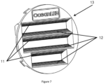
- the upper and lower reflectors 11, 12 are formed within as part of a unitary reflecting component 13, as shown in Figure 7 .
- the upper and lower reflectors 11, 12 are angled to reflect the light emitted by the adjacent row of LEDs 9 upwards through a first fixed angle. In the embodiments of Figures 2 to 6 the first fixed angle is 10°.
- the shape of the upper reflectors 11 will differ from the shape of the lower reflectors 12 in order to direct the light appropriately.
- a second embodiment of a through-hull light 1 according to the present invention is shown in Figures 5 and 6 .
- the second embodiment is substantially the same as the first embodiment with the exception that the shape of the body 3 is cylindrical and thicker than in the body 3 of the first embodiment. Otherwise, the second embodiment of the invention has all of the same features as the first embodiment and the same reference numerals have been used for the features of the second embodiment.
- Figure 8 shows a cross-section through a unitary reflecting component 13, 13' of the through-hull lights 1, 1' of Figure 1 .
- the unitary reflecting component 13' is according to the prior art in which upper and lower reflectors 11', 12' are at equal and opposite angles to reflect light from the LEDs 9 directly outwards from the light.
- the next three unitary reflecting components 13 are formed to reflect the light upwards through a first fixed angle of 10°, 20°, or 30° respectively. This is achieved by angling the upper and lower reflectors 11, 12 appropriately.
- the lower reflectors 12 are angled more steeply than the upper reflectors 11 and as a result and due to the limited space within the chamber 7 the reflecting faces of the upper reflectors 11 are larger than the reflecting faces of the lower reflectors 12.
- a light redirecting film 14 is provided in front of the unitary reflecting component 13.
- the light redirecting film 14 is a film of transparent material that is formed and oriented to reflect light incident on an inner side upwards through a second fixed angle.
- the light redirecting film 14 acts to redirect light through an angle of 20°. This allows the light from the LEDs 9 to be redirected upwards by up to 50°.
- the combination of the upper and lower reflectors 11, 12 and the light redirecting film 14 shown in the Figures allows the light to be redirected by 40° or 50°.
- the right-most embodiment has a unitary reflecting component 13 that acts to redirect the light upwards by 30° and the light redirecting film 14 directs the light upwards by a further 20°.
- the adjacent embodiment has a unitary reflecting component 13 that acts to redirect the light upwards by 20° and the light redirecting film directs the light upwards by a further 20°, thereby redirecting light from the LEDs upwards by 40°.
- the light redirecting film 14 is provided immediately adjacent an inner side of the transparent screen 8.
- through-hull underwater lights 1 may comprise any component found in through-hull underwater lights according to the prior art. This includes, but is not limited, to waterproof seals, heat sinks, fixings, power supply cables, control panels, communication cables. For clarity, these features are not shown in the Figures or described above. It is believed that the position and operation of these features will be immediately apparent to the person skilled in the art.
Landscapes
- Engineering & Computer Science (AREA)
- General Engineering & Computer Science (AREA)
- Chemical & Material Sciences (AREA)
- Combustion & Propulsion (AREA)
- Mechanical Engineering (AREA)
- Ocean & Marine Engineering (AREA)
- Non-Portable Lighting Devices Or Systems Thereof (AREA)
Applications Claiming Priority (1)
| Application Number | Priority Date | Filing Date | Title |
|---|---|---|---|
| GB2203939.0A GB2616855B (en) | 2022-03-21 | 2022-03-21 | Through-hull light |
Publications (2)
| Publication Number | Publication Date |
|---|---|
| EP4249366A1 true EP4249366A1 (de) | 2023-09-27 |
| EP4249366B1 EP4249366B1 (de) | 2026-03-25 |
Family
ID=81344926
Family Applications (1)
| Application Number | Title | Priority Date | Filing Date |
|---|---|---|---|
| EP23163172.2A Active EP4249366B1 (de) | 2022-03-21 | 2023-03-21 | Durch den rumpf hindurchgehende leuchte |
Country Status (3)
| Country | Link |
|---|---|
| US (1) | US11964736B2 (de) |
| EP (1) | EP4249366B1 (de) |
| GB (1) | GB2616855B (de) |
Citations (4)
| Publication number | Priority date | Publication date | Assignee | Title |
|---|---|---|---|---|
| KR20110086733A (ko) * | 2008-11-19 | 2011-07-29 | 쓰리엠 이노베이티브 프로퍼티즈 컴파니 | 조명 기구 및 다른 조명 시스템에서의 광 관리를 위한 브루스터 각 필름 |
| US20110210676A1 (en) * | 2010-01-27 | 2011-09-01 | Beghelli S.P.A. | Public lighting device with high energetic efficiency |
| US8172434B1 (en) * | 2007-02-23 | 2012-05-08 | DeepSea Power and Light, Inc. | Submersible multi-color LED illumination system |
| KR20130002196U (ko) * | 2011-09-29 | 2013-04-08 | 치-센 린 | Led 램프 어셈블리 |
Family Cites Families (6)
| Publication number | Priority date | Publication date | Assignee | Title |
|---|---|---|---|---|
| US7044623B2 (en) * | 2003-11-21 | 2006-05-16 | Deepsea Power & Light | Thru-hull light |
| GB2413840B (en) * | 2004-05-07 | 2006-06-14 | Savage Marine Ltd | Underwater lighting |
| US20150159817A1 (en) * | 2013-12-09 | 2015-06-11 | Mark S. Olsson | Led illumination devices and methods |
| CN107923580B (zh) * | 2015-09-02 | 2020-02-07 | 亮锐控股有限公司 | Led模块和照明模块 |
| US9903561B1 (en) * | 2015-11-09 | 2018-02-27 | Abl Ip Holding Llc | Asymmetric vision enhancement optics, luminaires providing asymmetric light distributions and associated methods |
| BE1026261B1 (fr) * | 2018-05-08 | 2019-12-10 | Schreder Sa | Dispositif d’éclairage vers le bas et lampadaire comprenant un module d’éclairage sur mât doté de celui-ci |
-
2022
- 2022-03-21 GB GB2203939.0A patent/GB2616855B/en active Active
-
2023
- 2023-03-21 US US18/187,263 patent/US11964736B2/en active Active
- 2023-03-21 EP EP23163172.2A patent/EP4249366B1/de active Active
Patent Citations (4)
| Publication number | Priority date | Publication date | Assignee | Title |
|---|---|---|---|---|
| US8172434B1 (en) * | 2007-02-23 | 2012-05-08 | DeepSea Power and Light, Inc. | Submersible multi-color LED illumination system |
| KR20110086733A (ko) * | 2008-11-19 | 2011-07-29 | 쓰리엠 이노베이티브 프로퍼티즈 컴파니 | 조명 기구 및 다른 조명 시스템에서의 광 관리를 위한 브루스터 각 필름 |
| US20110210676A1 (en) * | 2010-01-27 | 2011-09-01 | Beghelli S.P.A. | Public lighting device with high energetic efficiency |
| KR20130002196U (ko) * | 2011-09-29 | 2013-04-08 | 치-센 린 | Led 램프 어셈블리 |
Also Published As
| Publication number | Publication date |
|---|---|
| EP4249366B1 (de) | 2026-03-25 |
| GB202203939D0 (en) | 2022-05-04 |
| US20230294801A1 (en) | 2023-09-21 |
| US11964736B2 (en) | 2024-04-23 |
| GB2616855A (en) | 2023-09-27 |
| GB2616855B (en) | 2025-04-02 |
Similar Documents
| Publication | Publication Date | Title |
|---|---|---|
| US7258472B2 (en) | Illuminated rubrail/bumper assembly | |
| US20100002435A1 (en) | Led light with a diffracting lens | |
| EP1742834B1 (de) | Unterwasserbeleuchtung | |
| US8277098B2 (en) | Boat lighting components and system | |
| US11084559B2 (en) | Outboard motor lighting system | |
| US20090237949A1 (en) | Flashing stern light for boats | |
| KR101941979B1 (ko) | 선박용 항해등 | |
| EP4249366B1 (de) | Durch den rumpf hindurchgehende leuchte | |
| JP2007236214A (ja) | 集魚灯 | |
| US20200172212A1 (en) | High-output multifunction submersible marine lighting apparatus | |
| US20030031030A1 (en) | Directional indicator light for boat | |
| KR101985451B1 (ko) | 선박의 거주구 구조 | |
| KR102173225B1 (ko) | 레저선박의 하우스모듈 도킹장치 | |
| JP2012216334A (ja) | 灯具 | |
| US11173985B2 (en) | Bracket for mounting a thruster to a boat | |
| SE9601836D0 (sv) | Båtskrov samt fartyg med ett dylikt skrov | |
| CA2966086A1 (en) | Illuminated headwear for watersports | |
| CN113371150B (zh) | 一种半潜船的桅灯系统及半潜船 | |
| US3254206A (en) | Nautical light | |
| US20080025033A1 (en) | Vessel Made of Internally Illuminated Light-Transmitting Material | |
| GB2324277A (en) | Production vessel with sinusoidal waterline hull | |
| CN115416821A (zh) | 海洋工程船航行信号灯布置结构 | |
| TWI519731B (zh) | 船舶燈號傳遞方法及系統 | |
| EP3760921B1 (de) | Beleuchtungsvorrichtung zur montage an einem schiff oder einer off-shore-installation oder einem pier in einer nautischen oder maritimen umgebung | |
| EP3401205B1 (de) | Integriertes beleuchtungs- und signalisierungssystem für vorrichtung mit integration von beleuchtung und signalisierung für navigationszwecke |
Legal Events
| Date | Code | Title | Description |
|---|---|---|---|
| PUAI | Public reference made under article 153(3) epc to a published international application that has entered the european phase |
Free format text: ORIGINAL CODE: 0009012 |
|
| STAA | Information on the status of an ep patent application or granted ep patent |
Free format text: STATUS: THE APPLICATION HAS BEEN PUBLISHED |
|
| AK | Designated contracting states |
Kind code of ref document: A1 Designated state(s): AL AT BE BG CH CY CZ DE DK EE ES FI FR GB GR HR HU IE IS IT LI LT LU LV MC ME MK MT NL NO PL PT RO RS SE SI SK SM TR |
|
| STAA | Information on the status of an ep patent application or granted ep patent |
Free format text: STATUS: REQUEST FOR EXAMINATION WAS MADE |
|
| 17P | Request for examination filed |
Effective date: 20240322 |
|
| RBV | Designated contracting states (corrected) |
Designated state(s): AL AT BE BG CH CY CZ DE DK EE ES FI FR GB GR HR HU IE IS IT LI LT LU LV MC ME MK MT NL NO PL PT RO RS SE SI SK SM TR |
|
| GRAP | Despatch of communication of intention to grant a patent |
Free format text: ORIGINAL CODE: EPIDOSNIGR1 |
|
| STAA | Information on the status of an ep patent application or granted ep patent |
Free format text: STATUS: GRANT OF PATENT IS INTENDED |
|
| INTG | Intention to grant announced |
Effective date: 20251015 |
|
| GRAS | Grant fee paid |
Free format text: ORIGINAL CODE: EPIDOSNIGR3 |
|
| GRAA | (expected) grant |
Free format text: ORIGINAL CODE: 0009210 |
|
| STAA | Information on the status of an ep patent application or granted ep patent |
Free format text: STATUS: THE PATENT HAS BEEN GRANTED |
|
| AK | Designated contracting states |
Kind code of ref document: B1 Designated state(s): AL AT BE BG CH CY CZ DE DK EE ES FI FR GB GR HR HU IE IS IT LI LT LU LV MC ME MK MT NL NO PL PT RO RS SE SI SK SM TR |
|
| REG | Reference to a national code |
Ref country code: CH Ref legal event code: F10 Free format text: ST27 STATUS EVENT CODE: U-0-0-F10-F00 (AS PROVIDED BY THE NATIONAL OFFICE) Effective date: 20260325 Ref country code: GB Ref legal event code: FG4D |
|
| REG | Reference to a national code |
Ref country code: DE Ref legal event code: R096 Ref document number: 602023013923 Country of ref document: DE |
|
| REG | Reference to a national code |
Ref country code: IE Ref legal event code: FG4D |