EP4249355A1 - Chariot de livraison - Google Patents
Chariot de livraison Download PDFInfo
- Publication number
- EP4249355A1 EP4249355A1 EP23163325.6A EP23163325A EP4249355A1 EP 4249355 A1 EP4249355 A1 EP 4249355A1 EP 23163325 A EP23163325 A EP 23163325A EP 4249355 A1 EP4249355 A1 EP 4249355A1
- Authority
- EP
- European Patent Office
- Prior art keywords
- suspension
- drive
- caterpillar drive
- circulating roller
- electric motor
- Prior art date
- Legal status (The legal status is an assumption and is not a legal conclusion. Google has not performed a legal analysis and makes no representation as to the accuracy of the status listed.)
- Pending
Links
- 239000000725 suspension Substances 0.000 claims abstract description 60
- 238000005096 rolling process Methods 0.000 claims abstract description 28
- 230000005540 biological transmission Effects 0.000 claims description 11
- 235000004443 Ricinus communis Nutrition 0.000 description 5
- 240000000528 Ricinus communis Species 0.000 description 5
- 230000002349 favourable effect Effects 0.000 description 2
- 238000010276 construction Methods 0.000 description 1
- 230000001419 dependent effect Effects 0.000 description 1
- 238000001514 detection method Methods 0.000 description 1
Images


Classifications
-
- B—PERFORMING OPERATIONS; TRANSPORTING
- B62—LAND VEHICLES FOR TRAVELLING OTHERWISE THAN ON RAILS
- B62B—HAND-PROPELLED VEHICLES, e.g. HAND CARTS OR PERAMBULATORS; SLEDGES
- B62B5/00—Accessories or details specially adapted for hand carts
- B62B5/0026—Propulsion aids
- B62B5/0033—Electric motors
- B62B5/0036—Arrangements of motors
-
- B—PERFORMING OPERATIONS; TRANSPORTING
- B62—LAND VEHICLES FOR TRAVELLING OTHERWISE THAN ON RAILS
- B62D—MOTOR VEHICLES; TRAILERS
- B62D63/00—Motor vehicles or trailers not otherwise provided for
- B62D63/02—Motor vehicles
-
- B—PERFORMING OPERATIONS; TRANSPORTING
- B62—LAND VEHICLES FOR TRAVELLING OTHERWISE THAN ON RAILS
- B62B—HAND-PROPELLED VEHICLES, e.g. HAND CARTS OR PERAMBULATORS; SLEDGES
- B62B5/00—Accessories or details specially adapted for hand carts
- B62B5/0026—Propulsion aids
- B62B5/0033—Electric motors
-
- B—PERFORMING OPERATIONS; TRANSPORTING
- B62—LAND VEHICLES FOR TRAVELLING OTHERWISE THAN ON RAILS
- B62D—MOTOR VEHICLES; TRAILERS
- B62D55/00—Endless track vehicles
- B62D55/02—Endless track vehicles with tracks and additional ground wheels
Definitions
- Such a delivery van is from the EP 0 711 698 A2 known.
- the chassis of the delivery vehicle is equipped with a device for overcoming step-like road misalignments, especially curbs.
- a ramp is provided that is set at an angle of at least 20° to the driving plane and is formed by a cleated belt that is guided over two deflection rollers.
- the lug belt is moved passively, with the force to overcome the curb being applied to the rear fixed rollers via wheel hub motors.
- this design has the disadvantage that the ramp has to be flat and therefore elongated to avoid self-locking, which means that the swivel castors have to move far back. Without your own drive, overcoming the obstacle is also difficult.
- the lug belt can be driven with an electric motor.
- the electric motor could be accommodated given the very limited space available.
- Wheel hub motors are mentioned for the fixed rollers, which, however, could not provide the required starting torque when installed within one of the deflection rollers. If the wheel hub motor were arranged axially outside the deflection roller, the problem would again be that the front steering rollers would collide with the wheel hub motor.
- a mobile device which is able to overcome obstacles.
- the device has a frame on which driven front and rear wheels as well as centrally arranged drive wheels are arranged.
- the drive wheels of the mobile device 100 are driven by the drive motors.
- the device also has a caterpillar drive for overcoming obstacles.
- This caterpillar drive consists of an endless element, a roller driving the endless element and a driven roller.
- the driving roller is moved by an electric motor.
- An actuator applies torque to a transmission rail. This allows the construction to swing downwards, which raises the mobile device. By lifting, the device can now move towards an obstacle and overcome it with the caterpillar.
- the electric motor and the actuator are arranged within a mounting housing, to the side of the caterpillar.
- the invention described below provides a suspension device for suspending the caterpillar drive on the chassis, the suspension device having two suspension parts on which the rear axle of the rear circulating roller and the front axle of the front circulating roller are mounted. It is also essential for the invention that the electric motor is arranged between the two suspension parts of the suspension device.
- This design has the advantage that a collision with the front wheels, which are designed in particular as swivel castors, can be reliably avoided, especially with strong steering angles and large diameters of the front wheels.
- the design according to the invention is therefore optimized for use in postal delivery vehicles.
- the WO 2016/111423 A1 The front and rear axles are not mounted on the suspension parts. Only that The front axle is mounted in a mounting housing in which the engine is housed.
- the WO 2016/111423 A1 Do not take the teaching to arrange the motor between two suspension parts.
- Sections of the mounting housing with the motors extend laterally outwards on each side of the endless element.
- the engine extends WO 2016/111423 A1 not between the two suspension parts, but underneath, so that the mounting housing protrudes laterally outwards from the front wheel bearing.
- the object of the present invention is to alleviate or eliminate at least individual disadvantages of the prior art.
- the invention has the particular aim of creating a delivery vehicle of the type mentioned at the beginning, in which the device for overcoming the road shoulder is adapted to the limited space below the loading space, with road levels being able to be reliably overcome without damaging the delivery vehicle, even with high loads.
- the electric motor is at least partially, in particular substantially completely, arranged between the two suspension parts of the suspension device.
- the location and Directional information such as “ horizontal “ , “ vertical “ , “ up “ , “ down “ , indicates the intended arrangement of the delivery vehicle on a flat, horizontal road.
- the track drive When driving on a flat, horizontal road, the track drive is raised off the road, with the forward or backward movement of the delivery truck being accomplished via the front and/or rear wheels on the chassis, with or without assistance from the user.
- the caterpillar drive is provided, which protrudes in front of the front wheels (seen in the direction of travel when driving straight ahead).
- the rolling surface of the track drive hits the road shoulder in front of the front wheels. Due to the rotating movement of the rolling surface in front of the shoulder of the road relative to the horizontal road, the front wheels are lifted off the road before the front wheels hit the shoulder of the road.
- a flat section of the rolling surface on the front of the caterpillar drive is inclined to the horizontal, for example at an angle of more than 20°, in particular of more than 30°, for example more than 40°, and preferably less than 88°.
- the caterpillar drive is equipped with an electric motor, which is set up to transmit power to the front or rear revolving roller.
- the electric motor is located, viewed in the horizontal direction, between the two suspension parts of the suspension device, on which the axes of the front and rear circulating rollers are mounted.
- the electric motor is therefore preferably arranged horizontally overlapping with the caterpillar drive.
- the electric motor is arranged in particular at the same transverse position in the transverse direction of the chassis.
- the electric motor is the WO 2016/111423 A1 arranged laterally next to the caterpillar.
- the electric motor does not protrude laterally, ie in the transverse direction of the chassis, beyond the suspension parts, which are preferably formed by vertically arranged suspension plates.
- a collision with the front wheels, which are designed in particular as swivel castors can be reliably avoided, especially at strong steering angles and large diameters of the front wheels.
- the arrangement of the electric motor between the suspension parts has the advantage that the electric motor is protected against external influences.
- the structure preferably has a flat base plate for arranging the goods to be transported, with the caterpillar drive being arranged under a front section of the flat base plate. Since the rolling surface of the caterpillar drive is positioned relative to the horizontal and the front revolving roller is therefore closer to the base plate, it is advantageous if the electric motor drives the rear revolving roller. With this version there is enough space between the suspension parts for the electric motor.
- the rolling surface is positioned below the center points of the front wheels in order to raise the front wheels so far before they hit the road shoulder that the front wheels can overcome the road shoulder.
- the caterpillar drive is arranged essentially centrally between the two front wheels in a preferred embodiment (seen in the direction of the connecting line between the centers of the front wheels).
- the caterpillar drive preferably has a caterpillar chain, in particular a belt chain, as an endless element.
- a design of the endless element as a rubber band chain is particularly preferred.
- the rolling surface corresponds to the main plane of the endless element at the front of the track drive.
- individual profiles which are preferably formed by strips, stand up from the rolling surface, which preferably has a flat rolling section.
- the caterpillar drive has the front and rear circulating rollers, which preferably have essentially the same diameter.
- the rear circulating roller is coupled to the motor in order to set the endless element in a rotating movement.
- the front circulating roller is preferably passive.
- the endless element can have guide teeth on the inside, into which teeth of the front and rear circulating rollers engage.
- the caterpillar drive has a gear, in particular a worm gear, between the electric motor and the rear circulating roller.
- a gear in particular a worm gear
- the gearbox With the help of the gearbox, a rotational movement of the motor can be transmitted to the rear revolving roller.
- a transmission element in particular a chain
- This version has proven to be particularly favorable for high payloads.
- the power flow can be effectively transmitted from the electric motor between the two suspension parts to the rear axle of the rear circulating roller.
- the transmission element is preferably guided via a front overdrive element, in particular a front ring gear, which is connected to an output shaft of the transmission.
- the transmission element is preferably guided via a rear overdrive element, in particular a rear ring gear, which is connected to the rear axle of the rear circulating roller.
- the rear overdrive element in particular the rear sprocket, has a larger diameter than the front overdrive element, in particular the front sprocket.
- the transmission element is preferably arranged outside the space between the two suspension parts.
- the transmission element can be covered with a removable cover.
- the suspension device is set up to suspend the caterpillar drive on the chassis.
- the suspension device preferably has two suspension plates, which are preferably arranged essentially vertically. In this version it is the caterpillar drive is stored between the two suspension plates.
- the front circulating roller is mounted on the front axle and the rear circulating roller is mounted on the suspension device, in particular on the two suspension plates, via the rear axle.
- the front axle is located further forward and higher up than the rear axle.
- the rear axle of the rear circulating roller is (apart from its rotational movement) essentially immovably mounted on the suspension device, in particular on two suspension plates of the suspension device, and the front axle of the front circulating roller is ( in addition to their rotational movement) along a guide, in particular along an elongated hole guide, movably mounted on the suspension device, in particular on the two suspension plates of the suspension device.
- the caterpillar drive has a spring device for elastic deflection of the rolling surface when it hits the shoulder of the road.
- the rolling surface can thus be elastically deflected, in particular pivoted, against the spring force of the spring device when it hits the road shoulder. In the unloaded state, the spring device is relaxed, causing the rolling surface to return to its starting position.
- the spring device has at least one coil spring, preferably two coil springs, wherein the at least one coil spring is preferably arranged substantially perpendicular to the rolling surface.
- the helical spring can therefore preferably be tensioned and relaxed substantially perpendicular to the rolling surface.
- a coil spring is preferably provided on opposite sides of the caterpillar drive.
- the spring device is connected to the front axle of the front circulating roller.
- one end of the spring device in particular the coil spring, is connected to the front axle of the front circulating roller and the other end of the spring device, in particular the coil spring, is connected to the suspension device.
- a sensor unit for detecting the shoulder of the road is preferably provided.
- the detection of the shoulder of the road with the sensor unit can be used to reduce the driving speed of the delivery vehicle so that the impact forces when hitting the shoulder of the road do not cause any damage.
- a rear wheel drive is preferably provided to drive the rear wheels.
- the rear wheel drive is coupled to the motor of the caterpillar drive in an operating mode for overcoming the road shoulder.
- both the rear-wheel drive and the caterpillar drive are switched on, with the driving speed of the delivery vehicle with the rear-wheel drive preferably being set to a predetermined value.
- the speed of the rear wheels is adjusted to overcome the shoulder of the road without causing damage to the delivery vehicle.
- a handling element in particular a handling bar, is provided for steering and/or pushing the delivery trolley.
- the delivery vehicle can have, in particular at the rear, a control element for operating, in particular, the motor of the caterpillar drive and/or the rear wheel drive.
- the drawing shows a delivery car 1, which is designed as a postal delivery car for transporting mail items such as letters and parcels.
- the delivery vehicle 1 has a chassis 2 on which two rear wheels 3 and two front wheels 4, here two swivel castors, are arranged.
- the rear wheels 3 are connected to a rear wheel drive 5, in particular an electric rear wheel motor, in order to move the delivery vehicle 1.
- the delivery trolley 1 has a handling element 6, here a handling bracket, with which the delivery trolley 1 can be steered and preferably the rear wheel drive 5 can also be supported by pushing.
- the delivery truck 1 has a control element 7, here a control panel, with which the user of the delivery truck 1 can set various functions, for example the speed of the rear wheel drive 5.
- the chassis 2 carries a structure 8 for receiving the goods to be transported.
- the structure 8 can have at least one access opening on one of the sides and/or on the top for access to the transported goods.
- the delivery vehicle 1 has a device 9 at the front for overcoming a shoulder of the road 10, which is illustrated in the drawing as a curb protruding from the road 11.
- the device 9 essentially points in the middle between the two front wheels 4 there is a caterpillar drive 12 to overcome the shoulder 10 of the road.
- the caterpillar drive 12 has an endless element 13, here a rotating belt chain, which has a rolling surface 14 on the front for rolling on the road shoulder.
- a flat section of the rolling surface 14 on the front of the caterpillar drive is inclined to the horizontal, for example at an angle of more than 20°, in particular of more than 30°, for example more than 40°, and preferably less than 88°.
- the rolling surface 14 is completely lifted off the underside of the rear wheels 3 and the front wheels 4, ie from the road surface 11, so that the rolling surface 14 is freely arranged in the air when driving on the flat road surface 11. Only when it hits the road shoulder 10 does the rolling surface 14 of the caterpillar drive 12 come into contact with the road shoulder 10. Due to the rotating movement of the endless element 13, the front of the delivery truck 1 is raised to such an extent that the front wheels 4 can overcome the shoulder 10 of the road.
- the endless element 13 also has profiles 14A, here profile strips, protruding from the rolling surface 14.
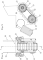
- the caterpillar drive 12 has an electric motor 15 (connected to a power supply, in particular a battery), with which the endless element 13 is set in a rotating movement.
- the caterpillar drive 12 has a front toothed revolving roller 16 and a rear toothed revolving roller 17, which each mesh with guide teeth 18 on the inside of the endless element 13.
- the caterpillar drive 12 has a transmission element 19, here a chain, which connects an output shaft 20 to a rear axle 21 of the rear circulating roller 17.
- the output shaft 20 is part of a gear 22, here a worm gear, which is coupled to the electric motor 15.
- a suspension device 23 is provided, which in the embodiment shown has two suspension plates 24 on both sides of the caterpillar drive 12 including an electric motor 15.
- the rear axle 21 of the rear circulation roller 17 is arranged essentially immovably on the two suspension plates 24 of the suspension device 23.
- a front axle 25 of the front circulating roller 16 is slidably mounted in guides, here elongated hole guides 26, which are formed on the opposite suspension plates 24.
- the caterpillar drive 12 has a spring device 27 for elastic deflection of the rolling surface 14 when it hits the road shoulder 10.
- the spring device 27 has two coil springs 28, which are arranged essentially perpendicular to the rolling surface 14.
- the coil springs 28 of the spring device 27 are connected to the front axle 25 of the front circulating roller 16 in such a way that the endless element 13 is displaced along the elongated hole guides 26 against the spring force of the coil springs 28 when it hits the road shoulder 10.
- the delivery truck 1 also has a sensor unit (not shown) for detecting the road shoulder 10. If the road shoulder 10 is detected with the sensor unit, the rear wheel drive 5 can be switched into an operating mode for overcoming the road shoulder 10, in which the rear wheels 3 are rotated at a predetermined speed, the endless element 13 of the caterpillar drive 12 also being moved with the electric motor 15 .
- Fig. 6 to 8 show schematically how to overcome the road shoulder 10 with the help of the caterpillar drive 12.
- the delivery vehicle 1 is moved forward on the flat, here horizontal roadway 11 exclusively via the rear wheels 3 at the rear end of the chassis 2.
- the caterpillar drive 12 first hits the road shoulder 10.
- the delivery vehicle is guided onto the road shoulder 10 in an operating mode with reduced speed of the rear wheel drive 5 and the caterpillar drive 12 activated.
- the front wheels 4 are driven over by the caterpillar drive 12 with the support of the rear wheels 3 lifted to shoulder 10.
Landscapes
- Engineering & Computer Science (AREA)
- Chemical & Material Sciences (AREA)
- Combustion & Propulsion (AREA)
- Transportation (AREA)
- Mechanical Engineering (AREA)
- Handcart (AREA)
Applications Claiming Priority (1)
| Application Number | Priority Date | Filing Date | Title |
|---|---|---|---|
| ATA50185/2022A AT526028A1 (de) | 2022-03-22 | 2022-03-22 | Zustellwagen |
Publications (1)
| Publication Number | Publication Date |
|---|---|
| EP4249355A1 true EP4249355A1 (fr) | 2023-09-27 |
Family
ID=85724921
Family Applications (1)
| Application Number | Title | Priority Date | Filing Date |
|---|---|---|---|
| EP23163325.6A Pending EP4249355A1 (fr) | 2022-03-22 | 2023-03-22 | Chariot de livraison |
Country Status (2)
| Country | Link |
|---|---|
| EP (1) | EP4249355A1 (fr) |
| AT (1) | AT526028A1 (fr) |
Citations (3)
| Publication number | Priority date | Publication date | Assignee | Title |
|---|---|---|---|---|
| US4061199A (en) * | 1974-12-03 | 1977-12-06 | Karl-Heinz Werner Toosbuy | Chassis for a vehicle capable of travelling over obstructions |
| EP0711698A2 (fr) | 1994-11-14 | 1996-05-15 | EXPRESSO DEUTSCHLAND TRANSPORTGERÄTE GmbH | Véhicule de distribution ou de transport |
| WO2016111423A1 (fr) | 2015-01-09 | 2016-07-14 | 한화테크윈 주식회사 | Dispositif mobile |
-
2022
- 2022-03-22 AT ATA50185/2022A patent/AT526028A1/de unknown
-
2023
- 2023-03-22 EP EP23163325.6A patent/EP4249355A1/fr active Pending
Patent Citations (3)
| Publication number | Priority date | Publication date | Assignee | Title |
|---|---|---|---|---|
| US4061199A (en) * | 1974-12-03 | 1977-12-06 | Karl-Heinz Werner Toosbuy | Chassis for a vehicle capable of travelling over obstructions |
| EP0711698A2 (fr) | 1994-11-14 | 1996-05-15 | EXPRESSO DEUTSCHLAND TRANSPORTGERÄTE GmbH | Véhicule de distribution ou de transport |
| WO2016111423A1 (fr) | 2015-01-09 | 2016-07-14 | 한화테크윈 주식회사 | Dispositif mobile |
Also Published As
| Publication number | Publication date |
|---|---|
| AT526028A1 (de) | 2023-10-15 |
Similar Documents
| Publication | Publication Date | Title |
|---|---|---|
| EP3663488B1 (fr) | Robot de stationnement pour un véhicule automobile | |
| DE602005004182T2 (de) | Anhänger mit heb- und senkbarer Manövrieranordnung | |
| EP3845482B1 (fr) | Véhicule de transport sans conducteur avec une plateforme de chargement qui peut être soulevée et descendue au moyen d'un entraînement à broche filetée | |
| DE1924223C3 (de) | Seitenlader | |
| EP3426593B2 (fr) | Véhicule de transport sans conducteur | |
| EP0596478A1 (fr) | Installation de parcage pour véhicules et procédé d'opération | |
| DE202008004190U1 (de) | Roll- oder Gelenkanordnung | |
| DE102010004974A1 (de) | Fördersystem zum Transport von Gegenständen und Tauchbehandlungsanlage mit einem solchen | |
| DE102014004089B4 (de) | Sortierförderer mit auf Fahrwagen abgestützten Tragwagen | |
| WO2015021567A1 (fr) | Transporteur pourvu d'un organe de transport étendu à plat | |
| DE102020104801A1 (de) | Fahrerloses Transportfahrzeug mit einer mittels eines Gewindespindelantriebs anhebbaren und absenkbaren Lastaufnahmeplattform | |
| DE102011076517B4 (de) | Handgeführter elektrisch angetriebener Flurförderwagen | |
| DE102018222232A1 (de) | Lenkeinrichtung für eine lenkbare Radachse eines Kraftfahrzeugs | |
| EP3484770B1 (fr) | Véhicule de transport | |
| EP4249355A1 (fr) | Chariot de livraison | |
| EP3309111B1 (fr) | Chariot de manutention | |
| DE102010034627B4 (de) | Kettenfahrzeug | |
| DE102009018052A1 (de) | Radarmunterstützter Mehrweg-Stapler, insbesondere Mehrwege-Schubmaststapler oder Mehrwege-Schubgabelstapler mit Omnidirektional-Rädern und Verfahren zum Betreiben eines Mehrwege-Staplers | |
| WO2021233505A1 (fr) | Véhicule de transport sans conducteur ayant un appareil de levage de charge utile | |
| EP4153524A1 (fr) | Véhicule de transport sans conducteur ayant un appareil de levage de charge utile et un appareil de fixation | |
| DE10319448A1 (de) | Lenkantrieb mit einem Lenkaktuator für zwei Drehschemel | |
| DE102019101857A1 (de) | Fahrzeug zum Anheben, Transportieren und Absenken von Ladungsträgern | |
| DE202004001810U1 (de) | Transportwagen und Stauförderer mit einer Mehrzahl solcher Transportwagen | |
| DE102015100815A1 (de) | Mitnahmestapler | |
| DE102009057477A1 (de) | Sicherheitskabine für den Bediener eines Portalstaplers |
Legal Events
| Date | Code | Title | Description |
|---|---|---|---|
| PUAI | Public reference made under article 153(3) epc to a published international application that has entered the european phase |
Free format text: ORIGINAL CODE: 0009012 |
|
| STAA | Information on the status of an ep patent application or granted ep patent |
Free format text: STATUS: THE APPLICATION HAS BEEN PUBLISHED |
|
| AK | Designated contracting states |
Kind code of ref document: A1 Designated state(s): AL AT BE BG CH CY CZ DE DK EE ES FI FR GB GR HR HU IE IS IT LI LT LU LV MC ME MK MT NL NO PL PT RO RS SE SI SK SM TR |
|
| STAA | Information on the status of an ep patent application or granted ep patent |
Free format text: STATUS: REQUEST FOR EXAMINATION WAS MADE |
|
| 17P | Request for examination filed |
Effective date: 20240322 |
|
| RBV | Designated contracting states (corrected) |
Designated state(s): AL AT BE BG CH CY CZ DE DK EE ES FI FR GB GR HR HU IE IS IT LI LT LU LV MC ME MK MT NL NO PL PT RO RS SE SI SK SM TR |