EP4249355A1 - Delivery carriage - Google Patents
Delivery carriage Download PDFInfo
- Publication number
- EP4249355A1 EP4249355A1 EP23163325.6A EP23163325A EP4249355A1 EP 4249355 A1 EP4249355 A1 EP 4249355A1 EP 23163325 A EP23163325 A EP 23163325A EP 4249355 A1 EP4249355 A1 EP 4249355A1
- Authority
- EP
- European Patent Office
- Prior art keywords
- suspension
- drive
- caterpillar drive
- circulating roller
- electric motor
- Prior art date
- Legal status (The legal status is an assumption and is not a legal conclusion. Google has not performed a legal analysis and makes no representation as to the accuracy of the status listed.)
- Pending
Links
- 239000000725 suspension Substances 0.000 claims abstract description 60
- 238000005096 rolling process Methods 0.000 claims abstract description 28
- 230000005540 biological transmission Effects 0.000 claims description 11
- 235000004443 Ricinus communis Nutrition 0.000 description 5
- 240000000528 Ricinus communis Species 0.000 description 5
- 230000002349 favourable effect Effects 0.000 description 2
- 238000010276 construction Methods 0.000 description 1
- 230000001419 dependent effect Effects 0.000 description 1
- 238000001514 detection method Methods 0.000 description 1
Images


Classifications
-
- B—PERFORMING OPERATIONS; TRANSPORTING
- B62—LAND VEHICLES FOR TRAVELLING OTHERWISE THAN ON RAILS
- B62B—HAND-PROPELLED VEHICLES, e.g. HAND CARTS OR PERAMBULATORS; SLEDGES
- B62B5/00—Accessories or details specially adapted for hand carts
- B62B5/0026—Propulsion aids
- B62B5/0033—Electric motors
- B62B5/0036—Arrangements of motors
-
- B—PERFORMING OPERATIONS; TRANSPORTING
- B62—LAND VEHICLES FOR TRAVELLING OTHERWISE THAN ON RAILS
- B62D—MOTOR VEHICLES; TRAILERS
- B62D63/00—Motor vehicles or trailers not otherwise provided for
- B62D63/02—Motor vehicles
-
- B—PERFORMING OPERATIONS; TRANSPORTING
- B62—LAND VEHICLES FOR TRAVELLING OTHERWISE THAN ON RAILS
- B62B—HAND-PROPELLED VEHICLES, e.g. HAND CARTS OR PERAMBULATORS; SLEDGES
- B62B5/00—Accessories or details specially adapted for hand carts
- B62B5/0026—Propulsion aids
- B62B5/0033—Electric motors
-
- B—PERFORMING OPERATIONS; TRANSPORTING
- B62—LAND VEHICLES FOR TRAVELLING OTHERWISE THAN ON RAILS
- B62D—MOTOR VEHICLES; TRAILERS
- B62D55/00—Endless track vehicles
- B62D55/02—Endless track vehicles with tracks and additional ground wheels
Definitions
- Such a delivery van is from the EP 0 711 698 A2 known.
- the chassis of the delivery vehicle is equipped with a device for overcoming step-like road misalignments, especially curbs.
- a ramp is provided that is set at an angle of at least 20° to the driving plane and is formed by a cleated belt that is guided over two deflection rollers.
- the lug belt is moved passively, with the force to overcome the curb being applied to the rear fixed rollers via wheel hub motors.
- this design has the disadvantage that the ramp has to be flat and therefore elongated to avoid self-locking, which means that the swivel castors have to move far back. Without your own drive, overcoming the obstacle is also difficult.
- the lug belt can be driven with an electric motor.
- the electric motor could be accommodated given the very limited space available.
- Wheel hub motors are mentioned for the fixed rollers, which, however, could not provide the required starting torque when installed within one of the deflection rollers. If the wheel hub motor were arranged axially outside the deflection roller, the problem would again be that the front steering rollers would collide with the wheel hub motor.
- a mobile device which is able to overcome obstacles.
- the device has a frame on which driven front and rear wheels as well as centrally arranged drive wheels are arranged.
- the drive wheels of the mobile device 100 are driven by the drive motors.
- the device also has a caterpillar drive for overcoming obstacles.
- This caterpillar drive consists of an endless element, a roller driving the endless element and a driven roller.
- the driving roller is moved by an electric motor.
- An actuator applies torque to a transmission rail. This allows the construction to swing downwards, which raises the mobile device. By lifting, the device can now move towards an obstacle and overcome it with the caterpillar.
- the electric motor and the actuator are arranged within a mounting housing, to the side of the caterpillar.
- the invention described below provides a suspension device for suspending the caterpillar drive on the chassis, the suspension device having two suspension parts on which the rear axle of the rear circulating roller and the front axle of the front circulating roller are mounted. It is also essential for the invention that the electric motor is arranged between the two suspension parts of the suspension device.
- This design has the advantage that a collision with the front wheels, which are designed in particular as swivel castors, can be reliably avoided, especially with strong steering angles and large diameters of the front wheels.
- the design according to the invention is therefore optimized for use in postal delivery vehicles.
- the WO 2016/111423 A1 The front and rear axles are not mounted on the suspension parts. Only that The front axle is mounted in a mounting housing in which the engine is housed.
- the WO 2016/111423 A1 Do not take the teaching to arrange the motor between two suspension parts.
- Sections of the mounting housing with the motors extend laterally outwards on each side of the endless element.
- the engine extends WO 2016/111423 A1 not between the two suspension parts, but underneath, so that the mounting housing protrudes laterally outwards from the front wheel bearing.
- the object of the present invention is to alleviate or eliminate at least individual disadvantages of the prior art.
- the invention has the particular aim of creating a delivery vehicle of the type mentioned at the beginning, in which the device for overcoming the road shoulder is adapted to the limited space below the loading space, with road levels being able to be reliably overcome without damaging the delivery vehicle, even with high loads.
- the electric motor is at least partially, in particular substantially completely, arranged between the two suspension parts of the suspension device.
- the location and Directional information such as “ horizontal “ , “ vertical “ , “ up “ , “ down “ , indicates the intended arrangement of the delivery vehicle on a flat, horizontal road.
- the track drive When driving on a flat, horizontal road, the track drive is raised off the road, with the forward or backward movement of the delivery truck being accomplished via the front and/or rear wheels on the chassis, with or without assistance from the user.
- the caterpillar drive is provided, which protrudes in front of the front wheels (seen in the direction of travel when driving straight ahead).
- the rolling surface of the track drive hits the road shoulder in front of the front wheels. Due to the rotating movement of the rolling surface in front of the shoulder of the road relative to the horizontal road, the front wheels are lifted off the road before the front wheels hit the shoulder of the road.
- a flat section of the rolling surface on the front of the caterpillar drive is inclined to the horizontal, for example at an angle of more than 20°, in particular of more than 30°, for example more than 40°, and preferably less than 88°.
- the caterpillar drive is equipped with an electric motor, which is set up to transmit power to the front or rear revolving roller.
- the electric motor is located, viewed in the horizontal direction, between the two suspension parts of the suspension device, on which the axes of the front and rear circulating rollers are mounted.
- the electric motor is therefore preferably arranged horizontally overlapping with the caterpillar drive.
- the electric motor is arranged in particular at the same transverse position in the transverse direction of the chassis.
- the electric motor is the WO 2016/111423 A1 arranged laterally next to the caterpillar.
- the electric motor does not protrude laterally, ie in the transverse direction of the chassis, beyond the suspension parts, which are preferably formed by vertically arranged suspension plates.
- a collision with the front wheels, which are designed in particular as swivel castors can be reliably avoided, especially at strong steering angles and large diameters of the front wheels.
- the arrangement of the electric motor between the suspension parts has the advantage that the electric motor is protected against external influences.
- the structure preferably has a flat base plate for arranging the goods to be transported, with the caterpillar drive being arranged under a front section of the flat base plate. Since the rolling surface of the caterpillar drive is positioned relative to the horizontal and the front revolving roller is therefore closer to the base plate, it is advantageous if the electric motor drives the rear revolving roller. With this version there is enough space between the suspension parts for the electric motor.
- the rolling surface is positioned below the center points of the front wheels in order to raise the front wheels so far before they hit the road shoulder that the front wheels can overcome the road shoulder.
- the caterpillar drive is arranged essentially centrally between the two front wheels in a preferred embodiment (seen in the direction of the connecting line between the centers of the front wheels).
- the caterpillar drive preferably has a caterpillar chain, in particular a belt chain, as an endless element.
- a design of the endless element as a rubber band chain is particularly preferred.
- the rolling surface corresponds to the main plane of the endless element at the front of the track drive.
- individual profiles which are preferably formed by strips, stand up from the rolling surface, which preferably has a flat rolling section.
- the caterpillar drive has the front and rear circulating rollers, which preferably have essentially the same diameter.
- the rear circulating roller is coupled to the motor in order to set the endless element in a rotating movement.
- the front circulating roller is preferably passive.
- the endless element can have guide teeth on the inside, into which teeth of the front and rear circulating rollers engage.
- the caterpillar drive has a gear, in particular a worm gear, between the electric motor and the rear circulating roller.
- a gear in particular a worm gear
- the gearbox With the help of the gearbox, a rotational movement of the motor can be transmitted to the rear revolving roller.
- a transmission element in particular a chain
- This version has proven to be particularly favorable for high payloads.
- the power flow can be effectively transmitted from the electric motor between the two suspension parts to the rear axle of the rear circulating roller.
- the transmission element is preferably guided via a front overdrive element, in particular a front ring gear, which is connected to an output shaft of the transmission.
- the transmission element is preferably guided via a rear overdrive element, in particular a rear ring gear, which is connected to the rear axle of the rear circulating roller.
- the rear overdrive element in particular the rear sprocket, has a larger diameter than the front overdrive element, in particular the front sprocket.
- the transmission element is preferably arranged outside the space between the two suspension parts.
- the transmission element can be covered with a removable cover.
- the suspension device is set up to suspend the caterpillar drive on the chassis.
- the suspension device preferably has two suspension plates, which are preferably arranged essentially vertically. In this version it is the caterpillar drive is stored between the two suspension plates.
- the front circulating roller is mounted on the front axle and the rear circulating roller is mounted on the suspension device, in particular on the two suspension plates, via the rear axle.
- the front axle is located further forward and higher up than the rear axle.
- the rear axle of the rear circulating roller is (apart from its rotational movement) essentially immovably mounted on the suspension device, in particular on two suspension plates of the suspension device, and the front axle of the front circulating roller is ( in addition to their rotational movement) along a guide, in particular along an elongated hole guide, movably mounted on the suspension device, in particular on the two suspension plates of the suspension device.
- the caterpillar drive has a spring device for elastic deflection of the rolling surface when it hits the shoulder of the road.
- the rolling surface can thus be elastically deflected, in particular pivoted, against the spring force of the spring device when it hits the road shoulder. In the unloaded state, the spring device is relaxed, causing the rolling surface to return to its starting position.
- the spring device has at least one coil spring, preferably two coil springs, wherein the at least one coil spring is preferably arranged substantially perpendicular to the rolling surface.
- the helical spring can therefore preferably be tensioned and relaxed substantially perpendicular to the rolling surface.
- a coil spring is preferably provided on opposite sides of the caterpillar drive.
- the spring device is connected to the front axle of the front circulating roller.
- one end of the spring device in particular the coil spring, is connected to the front axle of the front circulating roller and the other end of the spring device, in particular the coil spring, is connected to the suspension device.
- a sensor unit for detecting the shoulder of the road is preferably provided.
- the detection of the shoulder of the road with the sensor unit can be used to reduce the driving speed of the delivery vehicle so that the impact forces when hitting the shoulder of the road do not cause any damage.
- a rear wheel drive is preferably provided to drive the rear wheels.
- the rear wheel drive is coupled to the motor of the caterpillar drive in an operating mode for overcoming the road shoulder.
- both the rear-wheel drive and the caterpillar drive are switched on, with the driving speed of the delivery vehicle with the rear-wheel drive preferably being set to a predetermined value.
- the speed of the rear wheels is adjusted to overcome the shoulder of the road without causing damage to the delivery vehicle.
- a handling element in particular a handling bar, is provided for steering and/or pushing the delivery trolley.
- the delivery vehicle can have, in particular at the rear, a control element for operating, in particular, the motor of the caterpillar drive and/or the rear wheel drive.
- the drawing shows a delivery car 1, which is designed as a postal delivery car for transporting mail items such as letters and parcels.
- the delivery vehicle 1 has a chassis 2 on which two rear wheels 3 and two front wheels 4, here two swivel castors, are arranged.
- the rear wheels 3 are connected to a rear wheel drive 5, in particular an electric rear wheel motor, in order to move the delivery vehicle 1.
- the delivery trolley 1 has a handling element 6, here a handling bracket, with which the delivery trolley 1 can be steered and preferably the rear wheel drive 5 can also be supported by pushing.
- the delivery truck 1 has a control element 7, here a control panel, with which the user of the delivery truck 1 can set various functions, for example the speed of the rear wheel drive 5.
- the chassis 2 carries a structure 8 for receiving the goods to be transported.
- the structure 8 can have at least one access opening on one of the sides and/or on the top for access to the transported goods.
- the delivery vehicle 1 has a device 9 at the front for overcoming a shoulder of the road 10, which is illustrated in the drawing as a curb protruding from the road 11.
- the device 9 essentially points in the middle between the two front wheels 4 there is a caterpillar drive 12 to overcome the shoulder 10 of the road.
- the caterpillar drive 12 has an endless element 13, here a rotating belt chain, which has a rolling surface 14 on the front for rolling on the road shoulder.
- a flat section of the rolling surface 14 on the front of the caterpillar drive is inclined to the horizontal, for example at an angle of more than 20°, in particular of more than 30°, for example more than 40°, and preferably less than 88°.
- the rolling surface 14 is completely lifted off the underside of the rear wheels 3 and the front wheels 4, ie from the road surface 11, so that the rolling surface 14 is freely arranged in the air when driving on the flat road surface 11. Only when it hits the road shoulder 10 does the rolling surface 14 of the caterpillar drive 12 come into contact with the road shoulder 10. Due to the rotating movement of the endless element 13, the front of the delivery truck 1 is raised to such an extent that the front wheels 4 can overcome the shoulder 10 of the road.
- the endless element 13 also has profiles 14A, here profile strips, protruding from the rolling surface 14.
- the caterpillar drive 12 has an electric motor 15 (connected to a power supply, in particular a battery), with which the endless element 13 is set in a rotating movement.
- the caterpillar drive 12 has a front toothed revolving roller 16 and a rear toothed revolving roller 17, which each mesh with guide teeth 18 on the inside of the endless element 13.
- the caterpillar drive 12 has a transmission element 19, here a chain, which connects an output shaft 20 to a rear axle 21 of the rear circulating roller 17.
- the output shaft 20 is part of a gear 22, here a worm gear, which is coupled to the electric motor 15.
- a suspension device 23 is provided, which in the embodiment shown has two suspension plates 24 on both sides of the caterpillar drive 12 including an electric motor 15.
- the rear axle 21 of the rear circulation roller 17 is arranged essentially immovably on the two suspension plates 24 of the suspension device 23.
- a front axle 25 of the front circulating roller 16 is slidably mounted in guides, here elongated hole guides 26, which are formed on the opposite suspension plates 24.
- the caterpillar drive 12 has a spring device 27 for elastic deflection of the rolling surface 14 when it hits the road shoulder 10.
- the spring device 27 has two coil springs 28, which are arranged essentially perpendicular to the rolling surface 14.
- the coil springs 28 of the spring device 27 are connected to the front axle 25 of the front circulating roller 16 in such a way that the endless element 13 is displaced along the elongated hole guides 26 against the spring force of the coil springs 28 when it hits the road shoulder 10.
- the delivery truck 1 also has a sensor unit (not shown) for detecting the road shoulder 10. If the road shoulder 10 is detected with the sensor unit, the rear wheel drive 5 can be switched into an operating mode for overcoming the road shoulder 10, in which the rear wheels 3 are rotated at a predetermined speed, the endless element 13 of the caterpillar drive 12 also being moved with the electric motor 15 .
- Fig. 6 to 8 show schematically how to overcome the road shoulder 10 with the help of the caterpillar drive 12.
- the delivery vehicle 1 is moved forward on the flat, here horizontal roadway 11 exclusively via the rear wheels 3 at the rear end of the chassis 2.
- the caterpillar drive 12 first hits the road shoulder 10.
- the delivery vehicle is guided onto the road shoulder 10 in an operating mode with reduced speed of the rear wheel drive 5 and the caterpillar drive 12 activated.
- the front wheels 4 are driven over by the caterpillar drive 12 with the support of the rear wheels 3 lifted to shoulder 10.
Abstract
Zustellwagen (1), insbesondere Post-Zustellwagen, aufweisend:ein Fahrgestell (2), an welchem zwei Hinterräder (3), insbesondere zwei Antriebsräder, und zwei Vorderräder (4), insbesondere zwei Lenkrollen, angeordnet sind,ein vom Fahrgestell (2) getragener Aufbau (8) zur Aufnahme von Transportgut, insbesondere von Poststücken,eine Einrichtung (9) zur Überwindung eines Fahrbahnabsatzes (10), insbesondere einer Bordsteinkante, wobei die Einrichtung (9) einen Raupenantrieb (12) mit einer vorderen (16) und einer hinteren Umlaufrolle (17) aufweist, um welche ein Endloselement (13) mit einer Abrollfläche (14) umläuft, wobei der Raupenantrieb (12) weiters einen Elektromotor (15) aufweist,eine Aufhängeeinrichtung (23) zur Aufhängung des Raupenantriebs (12) am Fahrgestell (2), wobei die Aufhängeeinrichtung (23) zwei Aufhängeteile, insbesondere zwei Aufhängeplatten (24), aufweist, an welchen die hintere Achse (21) der hinteren Umlaufrolle (17) und die vordere Achse (25) der vorderen Umlaufrolle (17) gelagert sind, wobei der Elektromotor (15) zumindest teilweise, insbesondere im Wesentlichen vollständig, zwischen den zwei Aufhängeteilen der Aufhängeeinrichtung (23) angeordnet ist.Delivery trolley (1), in particular postal delivery trolley, comprising: a chassis (2), on which two rear wheels (3), in particular two drive wheels, and two front wheels (4), in particular two steering rollers, are arranged, one of the chassis (2) supported structure (8) for receiving goods to be transported, in particular mail items, a device (9) for overcoming a shoulder (10), in particular a curb, the device (9) having a caterpillar drive (12) with a front (16) and a rear circulating roller (17), around which an endless element (13) with a rolling surface (14) rotates, the caterpillar drive (12) further having an electric motor (15), a suspension device (23) for suspending the caterpillar drive (12) on the chassis (2), wherein the suspension device (23) has two suspension parts, in particular two suspension plates (24), on which the rear axle (21) of the rear circulation roller (17) and the front axle (25) of the front circulation roller (17) are mounted are, wherein the electric motor (15) is at least partially, in particular substantially completely, arranged between the two suspension parts of the suspension device (23).
Description
Die Erfindung betrifft einen Zustellwagen, insbesondere Post-Zustellwagen, aufweisend:
- ein Fahrgestell, an welchem zwei Hinterräder, insbesondere zwei Antriebsräder, und zwei Vorderräder, insbesondere zwei Lenkrollen, angeordnet sind,
- einen vom Fahrgestell getragenen Aufbau zur Aufnahme von Transportgut, insbesondere von Poststücken,
- eine Einrichtung zur Überwindung eines Fahrbahnabsatzes, insbesondere einer Bordsteinkante, wobei die Einrichtung einen Raupenantrieb mit einer vorderen und einer hinteren Umlaufrolle aufweist, um welche ein Endloselement mit einer Abrollfläche umläuft, wobei der Raupenantrieb weiters einen Elektromotor aufweist,
- eine Aufhängeeinrichtung zur Aufhängung des Raupenantriebs am Fahrgestell, wobei die Aufhängeeinrichtung zwei Aufhängeteile, insbesondere zwei Aufhängeplatten, aufweist, an welchen die hintere Achse der hinteren Umlaufrolle und die vordere Achse der vorderen Umlaufrolle gelagert sind.
- a chassis on which two rear wheels, in particular two drive wheels, and two front wheels, in particular two swivel castors, are arranged,
- a structure supported by the chassis for holding transported goods, in particular mail items,
- a device for overcoming a shoulder of the road, in particular a curb, the device having a caterpillar drive with a front and a rear roller around which an endless element with a rolling surface rotates, the caterpillar drive further having an electric motor,
- a suspension device for suspending the caterpillar drive on the chassis, the suspension device having two suspension parts, in particular two suspension plates, on which the rear axle of the rear circulating roller and the front axle of the front circulating roller are mounted.
Ein solcher Zustellwagen ist aus der
Aus der
Demzufolge besteht die Aufgabe der vorliegenden Erfindung darin, zumindest einzelne Nachteile des Standes der Technik zu lindern bzw. zu beheben. Die Erfindung setzt sich insbesondere zum Ziel, einen Zustellwagen der eingangs angeführten Art zu schaffen, bei welchem die Einrichtung zur Überwindung des Fahrbahnabsatzes an die beschränkten Platzverhältnisse unterhalb des Laderaums angepasst ist, wobei selbst bei hohen Zuladungen Fahrbahnabsätze ohne Beschädigung des Zustellwagens zuverlässig überwunden werden sollen.Accordingly, the object of the present invention is to alleviate or eliminate at least individual disadvantages of the prior art. The invention has the particular aim of creating a delivery vehicle of the type mentioned at the beginning, in which the device for overcoming the road shoulder is adapted to the limited space below the loading space, with road levels being able to be reliably overcome without damaging the delivery vehicle, even with high loads.
Diese Aufgabe wird durch einen Zustellwagen nach Anspruch 1 gelöst. Bevorzugte Ausführungsformen sind in den abhängigen Ansprüchen angegeben.This task is solved by a delivery truck according to
Erfindungsgemäß ist der Elektromotor zumindest teilweise, insbesondere im Wesentlichen vollständig, zwischen den zwei Aufhängeteilen der Aufhängeeinrichtung angeordnet.According to the invention, the electric motor is at least partially, in particular substantially completely, arranged between the two suspension parts of the suspension device.
Für die Zwecke dieser Offenbarung beziehen sich die Orts- und Richtungsangaben, wie "horizontal", "vertikal", "oben", "unten", auf die bestimmungsgemäße Anordnung des Zustellwagens auf einer ebenen, horizontalen Fahrbahn.For the purposes of this disclosure, the location and Directional information, such as " horizontal " , " vertical " , " up " , " down " , indicates the intended arrangement of the delivery vehicle on a flat, horizontal road.
Beim Fahren auf einer ebenen, horizontalen Fahrbahn ist der Raupenantrieb von der Fahrbahn abgehoben, wobei die Vorwärts- oder Rückwärtsbewegung) des Zustellwagens über die Vorder- und/oder Hinterräder am Fahrgestell, mit oder ohne Unterstützung durch den Benutzer, bewerkstelligt wird. Zur Überwindung eines Fahrbahnabsatzes ist der Raupenantrieb vorgesehen, welcher (in Fahrtrichtung bei Geradeausvorwärtsfahrt gesehen) vor die Vorderräder vorragt. Bei Erreichen des Fahrbahnabsatzes trifft die Abrollfläche des Raupenantriebs vor den Vorderrädern auf den Fahrbahnabsatz. Durch die umlaufende Bewegung der gegenüber der horizontalen Fahrbahn vor dem Fahrbahnabsatz angestellten Abrollfläche werden die Vorderräder von der Fahrbahn abgehoben, bevor die Vorderräder auf den Fahrbahnabsatz auftreffen. Bevorzugt ist ein ebener Abschnitt der Abrollfläche an der Vorderseite des Raupenantriebs, beispielsweise in einem Winkel von mehr als 20°, insbesondere von mehr als 30°, beispielsweise mehr als 40°, und vorzugsweise weniger als 88°, zur Horizontalen geneigt. Dadurch können die Vorderräder den Fahrbahnabsatz überwinden. Der Raupenantrieb ist dabei mit einem Elektromotor ausgestattet, welcher zur Kraftübertragung auf die vordere oder die hintere Umlaufrolle eingerichtet ist. Der Elektromotor befindet sich dabei, in horizontaler Richtung gesehen, zwischen den zwei Aufhängeteilen der Aufhängeeinrichtung, an welchen die Achsen der vorderen und hinteren Umlaufrolle gelagert sind. Somit ist der Elektromotor bevorzugt horizontal überlappend mit dem Raupenantrieb angeordnet. Vertikal von oben gesehen ist der Elektromotor dabei insbesondere an derselben Querposition in Querrichtung des Fahrgestells angeordnet. Demgegenüber ist der Elektromotor der
Bevorzugt weist der Aufbau eine ebene Bodenplatte zur Anordnung des Transportguts auf, wobei der Raupenantrieb unter einem vorderen Abschnitt der ebenen Bodenplatte angeordnet ist. Da die Abrollfläche des Raupenantriebs gegenüber der Horizontalen angestellt ist und die vordere Umlaufrolle daher näher an der Bodenplatte liegt, ist es günstig, wenn der Elektromotor die hintere Umlaufrolle antreibt. Bei dieser Ausführung ist zwischen den Aufhängeteilen ausreichend Platz für den Elektromotor.The structure preferably has a flat base plate for arranging the goods to be transported, with the caterpillar drive being arranged under a front section of the flat base plate. Since the rolling surface of the caterpillar drive is positioned relative to the horizontal and the front revolving roller is therefore closer to the base plate, it is advantageous if the electric motor drives the rear revolving roller. With this version there is enough space between the suspension parts for the electric motor.
Bei einer bevorzugten Ausführungsform setzt die Abrollfläche unterhalb der Mittelpunkte der Vorderräder an, um die Vorderräder vor dem Auftreffen auf den Fahrbahnabsatz so weit anzuheben, dass die Vorderräder den Fahrbahnabsatz überwinden können.In a preferred embodiment, the rolling surface is positioned below the center points of the front wheels in order to raise the front wheels so far before they hit the road shoulder that the front wheels can overcome the road shoulder.
Um das Überwinden des Fahrbahnabsatzes, insbesondere der Bordsteinkante, zu erleichtern, ist der Raupenantrieb bei einer bevorzugten Ausführungsform (in Richtung der Verbindungslinie zwischen den Mittelpunkten der Vorderräder gesehen) im Wesentlichen mittig zwischen den zwei Vorderrädern angeordnet.In order to make it easier to overcome the shoulder of the road, in particular the curb, the caterpillar drive is arranged essentially centrally between the two front wheels in a preferred embodiment (seen in the direction of the connecting line between the centers of the front wheels).
Als Endloselement weist der Raupenantrieb vorzugsweise eine Raupenkette, insbesondere eine Bandkette, auf. Besonders bevorzugt ist eine Ausführung des Endloselements als Gummibandkette.The caterpillar drive preferably has a caterpillar chain, in particular a belt chain, as an endless element. A design of the endless element as a rubber band chain is particularly preferred.
Die Abrollfläche entspricht der Hauptebene des Endloselements an der Vorderseite des Raupenantriebs. Bei einer bevorzugten Ausführungsform stehen von der, vorzugsweise einen ebenen Abrollabschnitt aufweisenden, Abrollfläche einzelne Profile hoch, welche bevorzugt durch Leisten gebildet sind.The rolling surface corresponds to the main plane of the endless element at the front of the track drive. In a preferred embodiment, individual profiles, which are preferably formed by strips, stand up from the rolling surface, which preferably has a flat rolling section.
Zur umlaufenden Bewegung des Endloselements weist der Raupenantrieb die vordere und die hintere Umlaufrolle auf, welche bevorzugt im Wesentlichen gleiche Durchmesser aufweisen. Bevorzugt ist nur die hintere Umlaufrolle mit dem Motor gekoppelt, um das Endloselement in eine umlaufende Bewegung zu versetzen. Die vordere Umlaufrolle ist bevorzugt passiv. Das Endloselement kann an der Innenseite Führungszähne aufweisen, in welche Zähne der vorderen und der hinteren Umlaufrolle eingreifen.For the rotating movement of the endless element, the caterpillar drive has the front and rear circulating rollers, which preferably have essentially the same diameter. Preferably, only the rear circulating roller is coupled to the motor in order to set the endless element in a rotating movement. The front circulating roller is preferably passive. The endless element can have guide teeth on the inside, into which teeth of the front and rear circulating rollers engage.
Bei einer besonders bevorzugten Ausführungsform weist der Raupenantrieb ein Getriebe, insbesondere ein Schneckengetriebe, zwischen dem Elektromotor und der hinteren Umlaufrolle auf. Mit Hilfe des Getriebes kann eine Rotationsbewegung des Motors auf die hintere Umlaufrolle übertragen werden.In a particularly preferred embodiment, the caterpillar drive has a gear, in particular a worm gear, between the electric motor and the rear circulating roller. With the help of the gearbox, a rotational movement of the motor can be transmitted to the rear revolving roller.
Weiters ist es günstig, wenn ein Transmissionselement, insbesondere eine Kette, zur Kraftübertragung vom Getriebe auf die hintere Umlaufrolle vorgesehen ist. Diese Ausführung hat sich für hohe Zuladungen als besonders günstig erwiesen. Zudem kann der Kraftfluss wirksam vom Elektromotor zwischen den zwei Aufhängeteilen auf die hintere Achse der hinteren Umlaufrolle übertragen werden. Das Transmissionselement ist bevorzugt über ein vorderes Übertriebselement, insbesondere einen vorderen Zahnkranz, geführt, welcher mit einer Abtriebswelle des Getriebes verbunden ist. Weiters ist das Transmissionselement bevorzugt über ein hinteres Übertriebselement, insbesondere einen hinteren Zahnkranz, geführt, welcher mit der hinteren Achse der hinteren Umlaufrolle verbunden ist. Vorzugsweise weist das hintere Übertriebselement, insbesondere der hintere Zahnkranz, einen größeren Durchmesser als das vordere Übertriebselement, insbesondere der vordere Zahnkranz, auf. Bevorzugt ist das Transmissionselement außerhalb des Raums zwischen den zwei Aufhängeteilen angeordnet. Das Transmissionselement kann mit einer abnehmbaren Abdeckhaube abgedeckt sein.Furthermore, it is favorable if a transmission element, in particular a chain, is provided for transmitting power from the transmission to the rear roller. This version has proven to be particularly favorable for high payloads. In addition, the power flow can be effectively transmitted from the electric motor between the two suspension parts to the rear axle of the rear circulating roller. The transmission element is preferably guided via a front overdrive element, in particular a front ring gear, which is connected to an output shaft of the transmission. Furthermore, the transmission element is preferably guided via a rear overdrive element, in particular a rear ring gear, which is connected to the rear axle of the rear circulating roller. Preferably, the rear overdrive element, in particular the rear sprocket, has a larger diameter than the front overdrive element, in particular the front sprocket. The transmission element is preferably arranged outside the space between the two suspension parts. The transmission element can be covered with a removable cover.
Die Aufhängeeinrichtung ist zur Aufhängung des Raupenantriebs am Fahrgestell eingerichtet. Bevorzugt weist die Aufhängeeinrichtung zwei Aufhängeplatten auf, die bevorzugt im Wesentlichen vertikal angeordnet sind. Bei dieser Ausführung ist der Raupenantrieb zwischen den zwei Aufhängeplatten gelagert. Die vordere Umlaufrolle ist über die vordere Achse und die hintere Umlaufrolle ist über die hintere Achse an der Aufhängeeinrichtung, insbesondere an den zwei Aufhängeplatten, gelagert. Die vordere Achse ist weiter vorne und weiter oben als die hintere Achse angeordnet.The suspension device is set up to suspend the caterpillar drive on the chassis. The suspension device preferably has two suspension plates, which are preferably arranged essentially vertically. In this version it is the caterpillar drive is stored between the two suspension plates. The front circulating roller is mounted on the front axle and the rear circulating roller is mounted on the suspension device, in particular on the two suspension plates, via the rear axle. The front axle is located further forward and higher up than the rear axle.
Um Beschädigungen beim Auftreffen auf den Fahrbahnabsatz vorzubeugen, ist die hintere Achse der hinteren Umlaufrolle bei einer bevorzugten Ausführungsform (abgesehen von ihrer Rotationsbewegung) im Wesentlichen unbeweglich an der Aufhängeeinrichtung, insbesondere an zwei Aufhängeplatten der Aufhängeeinrichtung, gelagert und die vordere Achse der vorderen Umlaufrolle ist (zusätzlich zu ihrer Rotationsbewegung) entlang einer Führung, insbesondere entlang einer Langlochführung, beweglich an der Aufhängeeinrichtung, insbesondere an den zwei Aufhängeplatten der Aufhängeeinrichtung, gelagert. Dadurch kann der Raupenantrieb beim Auftreffen auf den Fahrbahnabsatz verkippt werden, wobei die vordere Achse der vorderen Umlaufrolle entlang der Führung verschoben wird.In order to prevent damage when hitting the shoulder of the road, in a preferred embodiment the rear axle of the rear circulating roller is (apart from its rotational movement) essentially immovably mounted on the suspension device, in particular on two suspension plates of the suspension device, and the front axle of the front circulating roller is ( in addition to their rotational movement) along a guide, in particular along an elongated hole guide, movably mounted on the suspension device, in particular on the two suspension plates of the suspension device. This allows the caterpillar drive to be tilted when it hits the shoulder of the road, with the front axle of the front roller being moved along the guide.
Zum Schutz des Zustellwagens vor mechanischen Belastungen durch das Überwinden des Fahrbahnabsatzes ist es günstig, wenn der Raupenantrieb eine Federeinrichtung zur elastischen Auslenkung der Abrollfläche beim Auftreffen auf den Fahrbahnabsatz aufweist. Somit kann die Abrollfläche beim Auftreffen auf den Fahrbahnabsatz gegen die Federkraft der Federeinrichtung elastisch ausgelenkt, insbesondere verschwenkt, werden. Im unbelasteten Zustand wird die Federeinrichtung entspannt, wodurch die Abrollfläche in die Ausgangslage zurückkehrt.To protect the delivery vehicle from mechanical stress caused by overcoming the shoulder of the road, it is advantageous if the caterpillar drive has a spring device for elastic deflection of the rolling surface when it hits the shoulder of the road. The rolling surface can thus be elastically deflected, in particular pivoted, against the spring force of the spring device when it hits the road shoulder. In the unloaded state, the spring device is relaxed, causing the rolling surface to return to its starting position.
Bei einer bevorzugten Ausführungsform weist die Federeinrichtung zumindest eine Schraubenfeder, vorzugsweise zwei Schraubenfedern, auf, wobei die zumindest eine Schraubenfeder vorzugsweise im Wesentlichen senkrecht zur Abrollfläche angeordnet ist. Somit kann die Schraubenfeder vorzugsweise im Wesentlichen senkrecht zur Abrollfläche gespannt und entspannt werden. Bevorzugt ist je eine Schraubenfeder auf gegenüberliegenden Seiten des Raupenantriebs vorgesehen.In a preferred embodiment, the spring device has at least one coil spring, preferably two coil springs, wherein the at least one coil spring is preferably arranged substantially perpendicular to the rolling surface. The helical spring can therefore preferably be tensioned and relaxed substantially perpendicular to the rolling surface. A coil spring is preferably provided on opposite sides of the caterpillar drive.
Zum Auffangen der Aufprallkräfte ist es insbesondere günstig, wenn die Federeinrichtung mit der vorderen Achse der vorderen Umlaufrolle verbunden ist. Bevorzugt ist das eine Ende der Federeinrichtung, insbesondere der Schraubenfeder, mit der vorderen Achse der vorderen Umlaufrolle und das andere Ende der Federeinrichtung, insbesondere der Schraubenfeder, mit der Aufhängeeinrichtung verbunden.To absorb the impact forces, it is particularly advantageous if the spring device is connected to the front axle of the front circulating roller. Preferably, one end of the spring device, in particular the coil spring, is connected to the front axle of the front circulating roller and the other end of the spring device, in particular the coil spring, is connected to the suspension device.
Um die Überwindung des Fahrbahnabsatzes zu erleichtern, ist bevorzugt eine Sensoreinheit zur Erfassung des Fahrbahnabsatzes vorgesehen ist. Die Erfassung des Fahrbahnabsatzes mit der Sensoreinheit kann dazu genutzt werden, die Fahrgeschwindigkeit des Zustellwagens zu reduzieren, so dass die Aufprallkräfte beim Auftreffen auf den Fahrbahnabsatz keinen Schaden verursachen.In order to make it easier to overcome the shoulder of the road, a sensor unit for detecting the shoulder of the road is preferably provided. The detection of the shoulder of the road with the sensor unit can be used to reduce the driving speed of the delivery vehicle so that the impact forces when hitting the shoulder of the road do not cause any damage.
Um eine hohe Zuladung zu ermöglichen, ist bevorzugt ein Hinterradantrieb zum Antreiben der Hinterräder vorgesehen.In order to enable a high payload, a rear wheel drive is preferably provided to drive the rear wheels.
Bei einer bevorzugten Ausführungsform ist der Hinterradantrieb in einem Betriebsmodus zur Überwindung des Fahrbahnabsatzes mit dem Motor des Raupenantriebs gekoppelt. In diesem Betriebsmodus sind sowohl der Hinterradantrieb als auch der Raupenantrieb eingeschaltet, wobei die Fahrgeschwindigkeit des Zustellwagens mit dem Hinterradantrieb bevorzugt auf einen vorgegebenen Wert eingestellt ist. Die Geschwindigkeit der Hinterräder ist darauf abgestimmt, den Fahrbahnabsatz zu überwinden, ohne Schäden am Zustellwagen hervorzurufen.In a preferred embodiment, the rear wheel drive is coupled to the motor of the caterpillar drive in an operating mode for overcoming the road shoulder. In this operating mode, both the rear-wheel drive and the caterpillar drive are switched on, with the driving speed of the delivery vehicle with the rear-wheel drive preferably being set to a predetermined value. The speed of the rear wheels is adjusted to overcome the shoulder of the road without causing damage to the delivery vehicle.
Bei einer bevorzugten Ausführungsform ist ein Handhabungselement, insbesondere ein Handhabungsbügel, zum Lenken und/oder Schieben des Zustellwagens vorgesehen.In a preferred embodiment, a handling element, in particular a handling bar, is provided for steering and/or pushing the delivery trolley.
Der Zustellwagen kann, insbesondere an der Rückseite, ein Bedienelement zur Bedienung, insbesondere des Motors des Raupenantriebs und/oder des Hinterradantriebs, aufweisen.The delivery vehicle can have, in particular at the rear, a control element for operating, in particular, the motor of the caterpillar drive and/or the rear wheel drive.
Die Erfindung wird nachstehend anhand eines bevorzugten Ausführungsbeispiels weiter erläutert.
-
Fig. 1 zeigt einen erfindungsgemäßen Post-Zustellwagen. -
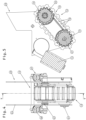
Fig. 2 zeigen verschiedene Ansichten eines Raupenantriebs zur Überwindung einer Bordsteinkante an der Vorderseite des Post-Zustellwagens.bis 4 -
Fig. 5 zeigt einen Schnitt entlang der Linie V-V inFig. 4 . -
Fig. 6 zeigen verschiedene Ansichten des erfindungsgemäßen Post-Zustellwagens beim Überwinden eines Fahrbahnabsatzes mit Hilfe des Raupenantriebs.bis 8
-
Fig. 1 shows a postal delivery van according to the invention. -
Fig. 2 to 4 show various views of a caterpillar drive for overcoming a curb on the front of the postal delivery vehicle. -
Fig. 5 shows a section along line VV inFig. 4 . -
Fig. 6 to 8 show different views of the postal delivery vehicle according to the invention when overcoming a step in the road with the help of the caterpillar drive.
Die Zeichnung zeigt einen Zustellwagen 1, welcher als Post-Zustellwagen zum Transport von Poststücken, wie Briefen und Paketen, ausgebildet ist. Der Zustellwagen 1 weist ein Fahrgestell 2 auf, an welchem zwei Hinterräder 3 und zwei Vorderräder 4, hier zwei Lenkrollen, angeordnet sind. Die Hinterräder 3 sind mit einem Hinterradantrieb 5, insbesondere einem Elektro-Hinterradmotor, verbunden, um den Zustellwagen 1 fortzubewegen. An der Rückseite weist der Zustellwagen 1 ein Handhabungselement 6, hier einen Handhabungsbügel, auf, mit welchem der Zustellwagen 1 gelenkt und bevorzugt zudem der Hinterradantrieb 5 durch Anschieben unterstützt werden kann. Ebenfalls an der Rückseite weist der Zustellwagen 1 ein Bedienelement 7, hier ein Bedienpaneel, auf, mit welchem der Benutzer des Zustellwagens 1 verschiedene Funktionen, beispielsweise die Geschwindigkeit des Hinterradantriebs 5, einstellen kann.The drawing shows a
Das Fahrgestell 2 trägt einen Aufbau 8 zur Aufnahme des Transportguts. Der Aufbau 8 kann an einer der Seiten und/oder an der Oberseite jeweils zumindest eine Zugangsöffnung zum Zugriff auf das Transportgut aufweisen.The
Darüber hinaus weist der Zustellwagen 1 vorne eine Einrichtung 9 zur Überwindung eines Fahrbahnabsatzes 10 auf, welcher in der Zeichnung als von der Fahrbahn 11 hochstehende Bordsteinkante veranschaulicht ist. Die Einrichtung 9 weist im Wesentlichen mittig zwischen den zwei Vorderrädern 4 einen Raupenantrieb 12 zur Überwindung des Fahrbahnabsatzes 10 auf. Der Raupenantrieb 12 weist ein Endloselement 13, hier eine umlaufende Bandkette, auf, welche an der Vorderseite eine Abrollfläche 14 zum Abrollen an dem Fahrbahnabsatz aufweist. Ein ebener Abschnitt der Abrollfläche 14 an der Vorderseite des Raupenantriebs ist, beispielsweise in einem Winkel von mehr als 20°, insbesondere von mehr als 30°, beispielsweise mehr als 40°, und vorzugsweise weniger als 88°, zur Horizontalen geneigt. Die Abrollfläche 14 ist von der Unterseite der Hinterräder 3 und der Vorderräder 4, d.h. von der Fahrbahn 11, vollständig abgehoben, so dass die Abrollfläche 14 bei der Fahrt auf der ebenen Fahrbahn 11 frei in der Luft angeordnet ist. Nur beim Auftreffen auf den Fahrbahnabsatz 10 kommt die Abrollfläche 14 des Raupenantriebs 12 mit dem Fahrbahnabsatz 10 in Kontakt. Durch die umlaufende Bewegung des Endloselements 13 wird der Zustellwagen 1 vorne so weit angehoben, dass die Vorderräder 4 den Fahrbahnabsatz 10 überwinden können. Das Endloselement 13 weist zudem von der Abrollfläche 14 hochstehende Profile 14A, hier Profilleisten, auf.In addition, the
Der Raupenantrieb 12 weist einen (mit einer Stromversorgung, insbesondere einem Akku, verbundenen) Elektromotor 15 auf, mit welchem das Endloselement 13 in eine umlaufende Bewegung versetzt wird. Der Raupenantrieb 12 weist eine vordere verzahnte Umlaufrolle 16 und eine hintere verzahnte Umlaufrolle 17 auf, welche jeweils mit Führungszähnen 18 an der Innenseite des Endloselements 13 kämmen. Zum Antrieb des Endloselements 13 weist der Raupenantrieb 12 ein Transmissionselement 19, hier eine Kette, auf, welche eine Abtriebswelle 20 mit einer hinteren Achse 21 der hinteren Umlaufrolle 17 verbindet. Die Abtriebswelle 20 ist Teil eines Getriebes 22, hier ein Schneckengetriebe, welches mit dem Elektromotor 15 gekoppelt ist.The
Zur Aufhängung des Raupenantriebs 12 am Fahrgestell 2 ist eine Aufhängeeinrichtung 23 vorgesehen, welche in der gezeigten Ausführung zwei Aufhängeplatten 24 beidseits des Raupenantriebs 12 samt Elektromotor 15 aufweist. Die hintere Achse 21 der hinteren Umlaufrolle 17 ist im Wesentlichen unbeweglich an den zwei Aufhängeplatten 24 der Aufhängeeinrichtung 23 angeordnet. Eine vordere Achse 25 der vorderen Umlaufrolle 16 ist verschieblich in Führungen, hier Langlochführungen 26, gelagert, welche an den gegenüberliegenden Aufhängeplatten 24 ausgebildet sind. Zudem weist der Raupenantrieb 12 eine Federeinrichtung 27 zur elastischen Auslenkung der Abrollfläche 14 beim Auftreffen auf den Fahrbahnabsatz 10 auf. Die Federeinrichtung 27 weist in der gezeigten Ausführung zwei Schraubenfedern 28 auf, welche im Wesentlichen senkrecht zur Abrollfläche 14 angeordnet sind. Die Schraubenfedern 28 der Federeinrichtung 27 sind derart mit der vorderen Achse 25 der vorderen Umlaufrolle 16 verbunden, dass das Endloselement 13 beim Auftreffen auf den Fahrbahnabsatz 10 gegen die Federkraft der Schraubenfedern 28 entlang der Langlochführungen 26 verschoben werden.To suspend the
Der Zustellwagen 1 weist zudem eine (nicht dargestellte) Sensoreinheit zur Erfassung des Fahrbahnabsatzes 10 auf. Wird der Fahrbahnabsatz 10 mit der Sensoreinheit erfasst, kann der Hinterradantrieb 5 in einen Betriebsmodus zur Überwindung des Fahrbahnabsatzes 10 geschaltet werden, in welchem die Hinterräder 3 mit einer vorgegebenen Geschwindigkeit gedreht werden, wobei zudem das Endloselement 13 des Raupenantriebs 12 mit dem Elektromotor 15 bewegt wird.The
Wie aus
Wie aus
Wie aus
- 1 Zustellwagen1 delivery van
- 2 Fahrgestell2 chassis
- 3 Hinterräder3 rear wheels
- 4 Vorderräder4 front wheels
- 5 Hinterradantrieb5 rear wheel drive
- 6 Handhabungselement6 handling element
- 7 Bedienelement7 control element
- 8 Aufbau8 Structure
- 9 Einrichtung zur Überwindung des Fahrbahnabsatzes9 Device for overcoming the road shoulder
- 10 Fahrbahnabsatz10 roadway paragraph
- 11 Fahrbahn11 lane
- 12 Raupenantrieb12 track drive
- 13 Endloselement13 endless element
- 14 Abrollfläche14 rolling surface
- 15 Elektromotor15 electric motor
- 16 vordere Umlaufrolle16 front circulation roller
- 17 hintere Umlaufrolle17 rear circulation roller
- 18 Führungszähne18 guide teeth
- 19 Transmissionselement19 transmission element
- 20 Abtriebswelle20 output shaft
- 21 hintere Achse der hinteren Umlaufrolle21 rear axle of the rear circulating roller
- 22 Getriebe22 gears
- 23 Aufhängeeinrichtung23 hanging device
- 24 Aufhängeplatten24 hanging plates
- 25 vordere Achse der vorderen Umlaufrolle25 front axle of the front circulating roller
- 26 Langlochführungen26 slotted hole guides
- 27 Federeinrichtung27 spring device
- 28 Schraubenfedern28 coil springs
Claims (11)
Applications Claiming Priority (1)
| Application Number | Priority Date | Filing Date | Title |
|---|---|---|---|
| ATA50185/2022A AT526028A1 (en) | 2022-03-22 | 2022-03-22 | Delivery van |
Publications (1)
| Publication Number | Publication Date |
|---|---|
| EP4249355A1 true EP4249355A1 (en) | 2023-09-27 |
Family
ID=85724921
Family Applications (1)
| Application Number | Title | Priority Date | Filing Date |
|---|---|---|---|
| EP23163325.6A Pending EP4249355A1 (en) | 2022-03-22 | 2023-03-22 | Delivery carriage |
Country Status (2)
| Country | Link |
|---|---|
| EP (1) | EP4249355A1 (en) |
| AT (1) | AT526028A1 (en) |
Citations (3)
| Publication number | Priority date | Publication date | Assignee | Title |
|---|---|---|---|---|
| US4061199A (en) * | 1974-12-03 | 1977-12-06 | Karl-Heinz Werner Toosbuy | Chassis for a vehicle capable of travelling over obstructions |
| EP0711698A2 (en) | 1994-11-14 | 1996-05-15 | EXPRESSO DEUTSCHLAND TRANSPORTGERÄTE GmbH | Distribution or transport trolley |
| WO2016111423A1 (en) | 2015-01-09 | 2016-07-14 | 한화테크윈 주식회사 | Moving device |
-
2022
- 2022-03-22 AT ATA50185/2022A patent/AT526028A1/en unknown
-
2023
- 2023-03-22 EP EP23163325.6A patent/EP4249355A1/en active Pending
Patent Citations (3)
| Publication number | Priority date | Publication date | Assignee | Title |
|---|---|---|---|---|
| US4061199A (en) * | 1974-12-03 | 1977-12-06 | Karl-Heinz Werner Toosbuy | Chassis for a vehicle capable of travelling over obstructions |
| EP0711698A2 (en) | 1994-11-14 | 1996-05-15 | EXPRESSO DEUTSCHLAND TRANSPORTGERÄTE GmbH | Distribution or transport trolley |
| WO2016111423A1 (en) | 2015-01-09 | 2016-07-14 | 한화테크윈 주식회사 | Moving device |
Also Published As
| Publication number | Publication date |
|---|---|
| AT526028A1 (en) | 2023-10-15 |
Similar Documents
| Publication | Publication Date | Title |
|---|---|---|
| DE602005004182T2 (en) | Trailer with raised and lowered maneuvering arrangement | |
| EP3663488B1 (en) | Parking robot for a motor vehicle | |
| EP3845482B1 (en) | Driverless transport vehicle with a load support platform which can be raised and lowered by a spindle drive | |
| DE1924223C3 (en) | Side loader | |
| EP3426593B2 (en) | Automated transport vehicle | |
| EP0596478A1 (en) | Vehicle parking apparatus and method for its operation | |
| DE202008004190U1 (en) | Roll or joint arrangement | |
| DE102010004974A1 (en) | Conveying system for transporting objects and dipping treatment plant with such | |
| DE102014004089B4 (en) | Sorting conveyor with wagons supported on vehicles | |
| WO2015021567A1 (en) | Conveying device having a large-area conveying member | |
| DE102020104801A1 (en) | Driverless transport vehicle with a load-bearing platform that can be raised and lowered by means of a threaded spindle drive | |
| DE102011076517B4 (en) | Hand-guided electrically driven industrial truck | |
| DE102018222232A1 (en) | Steering device for a steerable wheel axle of a motor vehicle | |
| EP3484770B1 (en) | Transport vehicle | |
| DE102006022242B4 (en) | Traveling System | |
| EP4249355A1 (en) | Delivery carriage | |
| EP3309111B1 (en) | Industrial truck | |
| DE102010034627B4 (en) | tracked vehicle | |
| DE102009018052A1 (en) | Wheel-arm-supported multi-directional fork lift e.g. multi-directional reach truck, has wheel arrangements supported at vehicle chassis for driving vehicle chassis in multiple directions and comprising omnidirectional wheels and drive unit | |
| WO2021233505A1 (en) | Driverless transport vehicle having a payload lifting apparatus | |
| EP4153524A1 (en) | Driverless transport vehicle having a payload lifting apparatus and securing apparatus | |
| DE10319448A1 (en) | Steering drive with one steering actuator for two turntables | |
| DE102019101857A1 (en) | Vehicle for lifting, transporting and lowering load carriers | |
| DE202004001810U1 (en) | Assembly trolley for accumulating roller conveyor has adjustable pressure of carrier on conveyor | |
| DE102015100815A1 (en) | Mitnahmestapler |
Legal Events
| Date | Code | Title | Description |
|---|---|---|---|
| PUAI | Public reference made under article 153(3) epc to a published international application that has entered the european phase |
Free format text: ORIGINAL CODE: 0009012 |
|
| STAA | Information on the status of an ep patent application or granted ep patent |
Free format text: STATUS: THE APPLICATION HAS BEEN PUBLISHED |
|
| AK | Designated contracting states |
Kind code of ref document: A1 Designated state(s): AL AT BE BG CH CY CZ DE DK EE ES FI FR GB GR HR HU IE IS IT LI LT LU LV MC ME MK MT NL NO PL PT RO RS SE SI SK SM TR |
|
| STAA | Information on the status of an ep patent application or granted ep patent |
Free format text: STATUS: REQUEST FOR EXAMINATION WAS MADE |