EP4249172A2 - Powered fastener driver - Google Patents
Powered fastener driver Download PDFInfo
- Publication number
- EP4249172A2 EP4249172A2 EP23186896.9A EP23186896A EP4249172A2 EP 4249172 A2 EP4249172 A2 EP 4249172A2 EP 23186896 A EP23186896 A EP 23186896A EP 4249172 A2 EP4249172 A2 EP 4249172A2
- Authority
- EP
- European Patent Office
- Prior art keywords
- piston
- motor
- battery pack
- crank arm
- controller
- Prior art date
- Legal status (The legal status is an assumption and is not a legal conclusion. Google has not performed a legal analysis and makes no representation as to the accuracy of the status listed.)
- Granted
Links
- 238000000034 method Methods 0.000 claims abstract description 59
- 238000004891 communication Methods 0.000 claims description 27
- 238000012360 testing method Methods 0.000 claims description 13
- 230000007246 mechanism Effects 0.000 description 45
- 230000033001 locomotion Effects 0.000 description 16
- 230000004044 response Effects 0.000 description 14
- 239000012530 fluid Substances 0.000 description 13
- 238000010008 shearing Methods 0.000 description 6
- 230000005540 biological transmission Effects 0.000 description 5
- 230000006835 compression Effects 0.000 description 5
- 238000007906 compression Methods 0.000 description 5
- 238000010586 diagram Methods 0.000 description 3
- 238000010276 construction Methods 0.000 description 2
- 230000003247 decreasing effect Effects 0.000 description 2
- 229920001971 elastomer Polymers 0.000 description 2
- 229910000831 Steel Inorganic materials 0.000 description 1
- XAGFODPZIPBFFR-UHFFFAOYSA-N aluminium Chemical compound [Al] XAGFODPZIPBFFR-UHFFFAOYSA-N 0.000 description 1
- 229910052782 aluminium Inorganic materials 0.000 description 1
- 238000013500 data storage Methods 0.000 description 1
- 239000000806 elastomer Substances 0.000 description 1
- 230000005669 field effect Effects 0.000 description 1
- 239000000463 material Substances 0.000 description 1
- 238000012986 modification Methods 0.000 description 1
- 230000004048 modification Effects 0.000 description 1
- 238000012545 processing Methods 0.000 description 1
- 239000012858 resilient material Substances 0.000 description 1
- 239000007787 solid Substances 0.000 description 1
- 239000010959 steel Substances 0.000 description 1
Images


Classifications
-
- B—PERFORMING OPERATIONS; TRANSPORTING
- B25—HAND TOOLS; PORTABLE POWER-DRIVEN TOOLS; MANIPULATORS
- B25C—HAND-HELD NAILING OR STAPLING TOOLS; MANUALLY OPERATED PORTABLE STAPLING TOOLS
- B25C1/00—Hand-held nailing tools; Nail feeding devices
- B25C1/04—Hand-held nailing tools; Nail feeding devices operated by fluid pressure, e.g. by air pressure
- B25C1/047—Mechanical details
-
- B—PERFORMING OPERATIONS; TRANSPORTING
- B25—HAND TOOLS; PORTABLE POWER-DRIVEN TOOLS; MANIPULATORS
- B25C—HAND-HELD NAILING OR STAPLING TOOLS; MANUALLY OPERATED PORTABLE STAPLING TOOLS
- B25C1/00—Hand-held nailing tools; Nail feeding devices
- B25C1/06—Hand-held nailing tools; Nail feeding devices operated by electric power
-
- B—PERFORMING OPERATIONS; TRANSPORTING
- B25—HAND TOOLS; PORTABLE POWER-DRIVEN TOOLS; MANIPULATORS
- B25C—HAND-HELD NAILING OR STAPLING TOOLS; MANUALLY OPERATED PORTABLE STAPLING TOOLS
- B25C1/00—Hand-held nailing tools; Nail feeding devices
- B25C1/008—Safety devices
Definitions
- the present disclosure relates to power tools, and more particularly to powered fastener drivers.
- fastener drivers used to drive fasteners (e.g., nails, tacks, staples, etc.) into a workpiece known in the art.
- fastener drivers operate utilizing various energy sources (e.g., compressed air generated by an air compressor, electrical energy, flywheel mechanisms) known in the art, but often these designs are met with power, size, and cost constraints.
- a powered fastener driver including a first cylinder, a first piston positioned within the first cylinder, the first piston being moveable between a top-dead-center position and at or near a bottom-dead-center position, a second cylinder in fluid communication with the first cylinder, a second piston positioned within the second cylinder, the second piston being moveable between a top-dead-center position and a bottom-dead-center position to initiate a fastener driving cycle, a drive blade coupled to the second piston for movement therewith, and a drive mechanism configured to drive the first piston between the top-dead-center position and at or near the bottom-dead-center position.
- the drive mechanism including a crank arm configured to rotate less than 360 degrees (°) for moving the first piston from at or near the bottom-dead-center position and the top-dead-center position and then back to at or near the bottom-dead-center position to complete the fastener driving cycle.
- a powered fastener driver including a first cylinder, a first piston positioned within the first cylinder, the first piston being moveable between a top-dead-center position and at or near a bottom-dead-center position, a second cylinder in fluid communication with the first cylinder, a second piston positioned within the second cylinder, the second piston being moveable between a top-dead-center position and a bottom-dead-center position to initiate a fastener driving cycle, a drive blade coupled to the second piston for movement therewith, and a drive mechanism configured to drive the first piston between the top-dead-center position and at or near the bottom-dead-center position.
- the drive mechanism including a crank arm having a stop surface configured to engage a fixed stop on a housing of the powered fastener driver both prior to and following completion of the fastener driving cycle.
- a powered fastener driver including a first cylinder, a first piston positioned within the first cylinder, the first piston being moveable between a top-dead-center position and at or near a bottom-dead-center position, a second cylinder in fluid communication with the first cylinder, a second piston positioned within the second cylinder, the second piston being moveable between a top-dead-center position and a bottom-dead-center position to initiate a fastener driving cycle, a drive blade coupled to the second piston for movement therewith, a drive mechanism configured to drive the first piston between the top-dead-center position and at or near the bottom-dead-center position to complete the fastener driving cycle, and a back-pressure adjustment mechanism in communication with the second cylinder, the back-pressure adjustment mechanism configured to adjust a volumetric flow rate of air exhausted from the second cylinder by the second piston during the fastener driving cycle.
- the disclosure provides, in another aspect, a method for controlling a motor of a power tool.
- the method comprising electrically braking, by a controller, the motor at a first time, and applying a pulse-width modulated (PWM) signal to the motor, by the controller, at a second time.
- PWM pulse-width modulated
- the second time is determined by determining, by the controller, a type of a battery pack electrically coupled to the power tool, and determining, by the controller, the second time based on the type of the battery pack.
- the disclosure provides, in another aspect, a method for controlling a motor of a powered fastener driver.
- the method comprising load testing a battery pack of the powered fastener driver by driving a crank arm against a fixed stop coupled to a housing of the powered fastener driver, determining, by a controller, an internal resistance of the battery pack by measuring one or both of a voltage and a current of the battery pack while driving the crank arm against the fixed stop, and determining, by the controller, a type of battery pack based on the determined internal resistance.
- a powered fastener driver 10 is operable to drive fasteners (e.g., nails, tacks, staples, etc.) held within a magazine 14 into a workpiece.
- the powered fastener driver 10 includes an outer housing with a handle portion 18, a structural housing 24, and a user-actuated trigger 26 mounted on the handle portion 18.
- the powered fastener driver 10 does not require an external source of air pressure, but rather the powered fastener driver 10 includes an on-board air compressor 30. In this way, the weight and/or size of tool may be reduced.
- the on-board air compressor 30 is powered by a power source (e.g., a battery pack 20), coupled to a battery attachment portion 22 of the outer housing.
- the powered fastener driver 10 includes a drive blade 34 actuated by the on-board air compressor 30 to drive the fasteners into a workpiece.
- the compressor 30 includes a compressor cylinder 38, a compressor piston 42 in the compressor cylinder 38, and a drive mechanism 44 that imparts reciprocating motion to the compressor piston 42 to execute one or more consecutive fastener driving cycles.
- the drive mechanism 44 includes a motor 46 (e.g., a brushed or brushless DC motor), a transmission 50 (e.g., a multistage planetary transmission), and a crank arm assembly 54 that converts a rotational output of the transmission 50 to a reciprocating input to the compressor piston 42.
- the fastener driver 10 also includes a drive cylinder 58 and a drive piston 62 slidably disposed in the drive cylinder 58.
- the drive piston 62 is movable between a top-dead-center (TDC) position ( FIG. 2 ) and a bottom-dead-center (BDC) position (e.g., when the drive piston 62 is adjacent a stop member 60).
- the compressor piston 42 is moveable between a TDC position (e.g., when the compressor piston 42 is adjacent a cylinder head 66) and a BDC position (e.g., when the compressor piston 42 is adjacent the crank arm assembly 54), or close to a BDC position.
- the drive cylinder 58 further includes a stop member 60 (e.g., a resilient bumper) positioned to engage and absorb energy from the drive piston 62 when the drive piston 62 reaches the BDC position.
- a stop member 60 e.g., a resilient bumper
- the smaller drive cylinder 58 may extend into and/or within the larger compressor cylinder 38 such that the compressor piston 42 may surround the entire drive cylinder 58.
- the size and/or weight of the fastener driver 10 may be advantageously reduced for improved handling, manufacturability, and/or the like. In this way, the fastener driver 10 may be easier for users to operate, and result in reduced user fatigue.
- the drive cylinder 58 and the compression cylinder 38 are in fluid communication by way of a passage 64 (see e.g., FIGS. 3 and 5 ).
- the passage 64 allows for the transmission of air and, therefore, air pressure between the two cylinders 38, 58.
- a cylinder head 66 is coupled to a distal end (e.g., an upper end) of the compression cylinder 38.
- the cylinder head 66 may include a plurality of apertures that define the passage 64, which allows for continuous fluid communication between the two cylinders 38, 58.
- the passage 64 may be devoid of a valve, in some cases.
- the compression cylinder 38 may be in continuous fluid communication such there is no selection or adjustment possible (e.g., the drive cylinder 58 and the compression cylinder 38 are always connected in an unchanging way).
- the powered fastener driver 10 may additionally include a latch 68 supported within the structural housing 24, which extends between the drive mechanism 44 and the drive blade 34.
- the latch 68 is movable between a locked position, in which the latch 68 engages the drive blade 34 to secure the drive piston 62 in the TDC position, and an unlocked position, in which the latch 68 disengages the drive blade 34 so the drive piston 62 is able to move from the TDC position to the BDC position to perform a fastener driving operation.
- the drive blade 34 includes a slot 70, and a biasing member 74 configured to bias the latch 68 towards the locked position.
- the latch 68 may further include a recess 72.
- the recess 72 is aligned with the drive blade 34.
- the slot 70 formed in the drive blade 34 is configured to receive a portion of the latch 68 to restrict movement of the drive blade 34.
- the crank arm assembly 54 includes a crank arm 76 with an eccentric pin 78 and a connecting rod 80 pivotably coupled to the pin 78 at one end and a piston pin 82 ( FIG. 2 ) at an opposite end.
- the crank arm 76 includes a hub 84 coupled for co-rotation with an output shaft of the transmission 50 (e.g., by a key and keyway arrangement).
- the crank arm assembly 54 also includes a cam 86 coupled for co-rotation with the crank arm 76.
- the cam 86 includes a first side 88, a second side 90 opposite the first side 88, and a cam lobe 92 formed on the first side 88.
- the cam lobe 92 is formed as a protrusion on the first side 88 of the cam 86 that extends in an axial direction and parallel with a rotational axis of the crank arm 76 and cam 86.
- one end of the latch 68 is biased against the first side 88 of the cam 86, resulting in sliding movement between the latch 68 and the cam 86 as the cam 86 rotates.
- the latch 68 slides up the cam lobe 92, the latch 68 is moved towards the unlocked position.
- the latch 68 behaves as a follower in response to rotation of the cam 86.
- crank arm assembly 54 is configured such that the crank arm 76 and the cam 86 may be configured to rotate less than 360° to execute a complete fastener driving cycle.
- a complete fastener driving cycle may be defined as the compressor piston 42 starting at a position near the BDC position, moving to the TDC position, and finishing at a position near the BDC position, while the drive piston 62 starts at TDC position, moves to the BDC position when the compressor piston 42 reaches the TDC position, and finishes in the TDC position.
- the crank arm assembly 54 rotates less than 360°.
- crank arm assembly 54 To initiate a subsequent compete fastener driving cycle, the rotation of the crank arm assembly 54 is reversed by the motor 46.
- the crank arm 76 and cam 86 rotate approximately 292° during a complete fastener driving cycle. In other embodiments, the crank arm 76 and cam 86 may rotate in a range from 250° to 350°.
- the motor 46 rotates the crank arm 76 and cam 86 alternately in a clockwise and a counterclockwise manner (e.g., clockwise then counterclockwise) to complete consecutive fastener driving cycles.
- the structural housing 24 includes a pair of fixed stops or stop structures (stop pins 102a, 102b) extending from an interior wall of the structural housing 24 adjacent the crank arm 76.
- the crank arm 76 includes a finger 98 extending radially outward from the hub 84 on the second side 90 of the cam 86.
- the stop pins 102a, 102b are positioned such that opposite sides of the finger 98, respectively, can engage the stop pins 102a, 102b at the start and the end of each fastener driving cycle to form a hard stop.
- the stop pins 102a, 102b are formed of rigid material (e.g., steel, aluminum, rigid plastic, and/or the like). In other embodiments, the stop pins 102a, 102b may be formed of a resilient material (e.g., rubber, elastomer, and/or the like). In the illustrated embodiment, the stop pins 102a, 102b and the width of the finger 98 define the angular range through which the crank arm 76 is able to rotate, as described above.
- the fastener driver 10 includes a back-pressure adjustment mechanism 106 supported within the structural housing 24.
- the back-pressure adjustment mechanism 106 is configured to vary the amount of air exhausted from the drive cylinder 58 beneath the drive piston 62 (i.e., on a side of the drive piston 62 opposite the cylinder head 66) during a fastener driving cycle. Because the fastener driver 10 may not include any pressure valves, the pressure of compressed air developed within the compressor cylinder 38 is the same and at a maximum value for each fastener driving cycle.
- the back-pressure adjustment mechanism 106 can selectively increase or decrease the amount of air exhausted from the drive cylinder 58 beneath the drive piston 62 as the drive piston 62 moves from the TDC position to the BDC position, thus either reducing or increasing, respectively, the back pressure acting on the drive piston 62 during a fastener driving cycle.
- the force acting on the drive piston 62 may be increased or decreased for driving different sizes of fasteners (e.g., 16 gauge nails, 18 gauge nails, 1 inch, 2 inch, and/or the like) to appropriate distances within a workpiece to make the fastener driver 10 suitable for use in a variety of different fastening applications.
- the back-pressure adjustment mechanism 106 may include a basket 108 rotatably supported within the structural housing 24, an adjustment member 110 extending from the basket 108 through the structural housing 24, and an opening 112 formed in the basket 108 to expose a central bore within the basket 108.
- the opening 112 in the basket 108 selectively aligns with a window 114 formed in the structural housing 24 which, in turn, is in fluid communication with the external atmosphere. Rotation of the basket 108 (e.g., via the adjustment member 110), adjusts the positioning of the opening 112 relative to the window 114, and thus the effective cross-sectional area of the opening 112 that is exposed to the atmosphere.
- Adjusting the size of the exposed opening 112 therefore, adjusts the volumetric flow rate of air that is exhausted from the drive cylinder 58 beneath the drive piston 62, through the exposed opening 112 and window 114. For example, reducing the size of the exposed opening 112 reduces the flow rate of air that can be exhausted through the opening 112, which creates a larger back-pressure acting against the drive piston 62 and thus reduces the net force acting on the drive piston 62 during a fastener driving cycle. Increasing the size of the exposed opening 112 increases the amount of air that can be exhausted through the opening 112, which creates a smaller back-pressure acting against the drive piston 62 and thus increases the net force acting on the drive piston 62 during a fastener driving cycle.
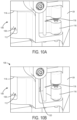
- fastener driver 10 also includes a check door 116 and a biasing member 118 (e.g., a torsion spring) that biases the check door 116 towards a closed position ( FIG. 10A ), which blocks the flow rate of air through a second window 120 ( FIG. 10B ) of the basket 108.
- a biasing member 118 e.g., a torsion spring
- the check door 116 is positioned adjacent the back-pressure adjustment mechanism 106 and is movable to an open position where the second window 120 in the basket 108 is opened to permit atmospheric air to enter the drive cylinder 58 via the basket 108 in response to the drive piston 62 moving from the BDC position toward the TDC position. More specifically, during the movement of the drive piston 62 from the BDC position toward the TDC position, a vacuum is created within the drive cylinder 58 beneath the drive piston 62 that pulls the check door 116 to the open position.
- the entire opening 112 of the basket 108 may be exposed to the atmosphere (via the first and second windows 114, 120 in the structural housing 24) so replacement air may enter the drive cylinder 58 beneath the drive piston 62.
- the vacuum acting on the check door 116 to hold the check door 116 in the open position dissipates, permitting the spring 118 to rebound and return the check door 116 to its closed position, thereby closing the second window 120, and resetting the driver 10 for a subsequent fastener driving cycle.
- the biasing member 74 also urges the latch 68 into engagement with the slot 70 of the drive blade 34, which locks the drive blade 34 in a position for the subsequent fastener driving cycle.
- the latch 68 maintains the drive piston 62 in the TDC position, while the compressor piston 42 is in the BDC position.
- One side of the finger 98 on the crank arm 76 is engaged with, for example, the stop pin 102a.
- the motor 46 is activated to rotate the crank arm 76 in a first rotational direction toward the stop pin 102a to confirm that the finger 98 is engaged with the stop pin 102a. This ensures the crank arm 76 is in a starting position at the beginning of a fastener driving cycle.
- the motor 46 is then rotated in an opposite direction to drive the compressor piston 42 upward toward its TDC position by the crank arm assembly 54. As the compressor piston 42 travels upward, the air in the compressor cylinder 38 and above the compressor piston 42 is compressed, while the latch 68 maintains the drive piston 62 in the TDC position.
- the latch 68 is moved into its unlocked position by the cam 86, which releases the drive blade 34 as described above.
- the drive piston 62 is accelerated downward within the drive cylinder 58 by the compressed air within the compressor cylinder 38, which causes the drive blade 34 to impact a fastener held in the magazine 14 and drive the fastener into a workpiece until the drive piston 62 reaches the stop member 60 located at the BDC position within the drive cylinder 58.
- the check door 116 opens, which allows replacement air to enter the drive cylinder 58 beneath the drive piston 62 to facilitate return of the drive piston 62 to the TDC position as described above.
- the biasing member 74 urges the latch 68 into the slot 70 of the drive blade 34, which locks the drive blade 34 in position for the subsequent fastener driving cycle.
- the rotational speed of the motor 46 is decreased after the fastener driving operation occurs such that the opposite side of the finger 98 engages the stop pin 102a, 102b at a low enough speed to prevent shearing of the stop pin 102a, 102b.
- the construction of the crank arm assembly 54 allows a control system 300, described in more detail below, to initiate a timer-based control of the motor 46, which permits the fastener driver 10 to be sensorless.
- the fastener driver 10 does not use any position sensors to detect the position of the compressor piston 42 or the drive piston 62. Rather, for the compressor piston 42 to execute the complete fastener driving cycle, the crank arm assembly 54 rotates less than 360° (e.g., 292° in the illustrated embodiment).
- the motor 46 rotates the crank arm 76 and cam 86 alternately in a clockwise and a counterclockwise manner (e.g., clockwise then counterclockwise).
- a timer may be used to set a timer duration for the complete fastener driving operation.
- the control system 300 brakes the motor 46 at a first time (e.g., to prevent shearing of the stop pin 102a, 102b), the finger 98 of the crank arm 76 engages the stop pin 102a, 102b at a second time, and after the crank arm 76 is stopped by the stop pin 102a, 102b, the motor 46 is stalled (e.g., still receives power but does not rotate) until a remainder of the timer duration is reached (e.g., a third time is reached). As such, this ensures the crank arm assembly 54 is positioned adjacent the stop pin 102a, 102b.
- a first time e.g., to prevent shearing of the stop pin 102a, 102b
- the finger 98 of the crank arm 76 engages the stop pin 102a, 102b at a second time
- the motor 46 is stalled (e.g., still receives power but does not rotate) until a remainder of the timer duration is reached (e.g
- FIG. 11 is a block diagram of a control system 300 of the powered fastener driver 10.
- the control system 300 may be used with other power tools.
- the control system 300 may include a controller 305, as well as other components not pictured in FIG. 11 , for example a motor 46, a solenoid, or other mechanical and/or electrical components described above.
- the controller 305 may include a processing unit 310 comprising a control unit 315, an arithmetic logic unit 320, and one or more registers 325.
- the controller 305 may further include a memory 330 consisting of program storage 335 and/or data storage 340.
- the memory 330 may be flash memory, random access memory, solid state memory, another type of memory, or a combination of these types.
- the controller 305 may further include one or more input units 345 and/or output units 350
- the battery pack 355 may include a stack 360 consisting of one or more battery cells 365.
- the one or more battery cells 365 are electrically connected to each other in a series-type manner.
- the one or more battery cells 365 are electrically connected to each other in a parallel-type manner.
- the one or more battery cells 365 are electrically connected to each other in a combination of a series-type and a parallel-type manner.
- the battery pack 355 may further include a battery controller 370 consisting of a battery processor 375 and a battery memory 380.
- the battery pack 355 may further include a positive battery terminal 385 and a negative battery terminal 390.
- the positive battery terminal 385 and the negative battery terminal 390 may be configured to electrically and/or mechanically couple to corresponding terminals of the powered fastener driver 10.
- the battery pack 355 includes a communication terminal 395, which may be configured to electrically, mechanically, and/or communicatively couple to one or more communication terminals of the powered fastener driver 10.
- the one or more battery cells 365 are connected to the battery controller 370.
- the battery controller 370 controls the power delivered to the positive battery terminal 385 and the negative battery terminal 390 (for example, via control of a discharge field-effect transistor (FET), a charge FET, and/or other FETs located within the battery pack).
- the battery pack controller 370 controls the power by allowing or prohibiting power.
- the battery pack controller 370 controls the power by allowing a percentage of power generated by the one or more battery cells 365 to be output.
- the amount of power delivered between the battery terminals 385, 390 is approximately 100% of power possibly generated by the one or more battery cells 365.
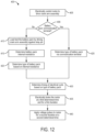
- FIG. 12 is a flowchart illustrating a method 400 for controlling a motor (e.g., the motor 46) of a power tool (e.g., the powered fastener driver 10), according to some embodiments.
- a motor e.g., the motor 46
- a power tool e.g., the powered fastener driver 10
- the method 400 includes electrically controlling, by the controller 305, the motor 46 to drive the crank arm assembly 54 (BLOCK 405).
- the motor 46 drives the crank arm assembly 54 in a first direction.
- the controller 305 may execute BLOCK 405 following BLOCK 408.
- the method 400 further includes determining, by the controller 305, whether a battery pack electrically, mechanically, and/or communicatively coupled to the power tool includes a communication terminal (BLOCK 408). If the controller 305 determines that the battery pack does not include a communication terminal, the controller 305 additionally includes load testing the battery pack by driving the crank arm assembly 54 against a stop pin 102a, 102b (BLOCK 410). The method 400 further includes determining, by the controller 305 an internal resistance of the battery pack (BLOCK 415). The controller 305 may determine the internal resistance by measuring a voltage and/or a current of the battery pack while driving the crank arm assembly 54 against the stop pin 102a, 102b.
- the method 400 then includes determining, by the controller 305, a type of battery pack based on the determined internal resistance (BLOCK 420). If the controller 305 determines that the battery pack does include a communication terminal (in BLOCK 410, the method 400 includes determining, by the controller 305, a type of battery pack by receiving a signal from the battery pack communication terminal (BLOCK 425).
- the method 400 includes determining, by the controller 305, a timing of one electrical cycle of the motor 46 (coinciding with one fastener driving cycle of the fastener driver 10) based on the determined type of the battery pack (BLOCK 430).
- the one electrical cycle may be the time between when the motor 46 begins driving the crank arm assembly 54 from a starting position to when the crank arm assembly 54 hits one of the stop pins 102a, 102b.
- the method 400 determines a first time and a second time.
- the method 400 further includes electrically braking, by the controller 305, the motor 46 at the determined first time and a first duration (BLOCK 435). Electrically braking the motor 46 may include electrically shorting the lead wires of the motor 46 together for the determined duration.
- the method 400 further includes applying a series of voltage pulses, by the controller 305, to the motor 46 for a second duration starting at the determined second time (BLOCK 440).
- the voltage pulses may correspond to a duty cycle of a pulse-width modulated (PWM) signal.
- PWM pulse-width modulated
- the braking of the motor 46 (at the first time and for the first duration) and the applying of the PWM signal (at the second time and for a portion of the second duration) may occur before the crank arm assembly 54 reaches one of the stop pins 102a, 102b.
- the PWM signal is continuously applied to the motor 46 after the crank arm assembly 54 engages the stop pin 102a, 102b, which causes the motor 46 to stall.
- the second duration where the PWM signal is applied to the motor 46 includes a time both prior to and after the crank arm assembly 54 engages the stop pin 102a, 102b.
- the crank arm assembly 54 is positioned adjacent the stop pin 102a, 102b for each fastener driving cycle.
- the controller 305 causes the motor 46 to drive the crank arm assembly 54 in a first direction in a first electrical cycle of the motor 46, wherein one electrical cycle is the time between when the motor 46 begins driving the crank arm assembly 54 from a starting position to when the crank arm assembly 54 hits one of the stop pins 102a, 102b.
- the controller 305 may then cause the motor 46 to drive the crank arm assembly 54 in a second direction, opposite the first direction, in a second electrical cycle of the motor 46.
- the motor 46 may alternatively drive the crank arm assembly 54 in this fashion in alternative cycles.
- the motor 46 may drive the crank arm assembly 54 in a clockwise direction, while in the second, fourth, sixth, and so-on cycles, the motor 46 may drive the crank arm assembly 54 in a counterclockwise direction, or vice versa.
- the signal to begin the first electrical cycle of the motor 46 may be based on an actuation of a trigger 26 or another switch of the power tool.
- the controller 305 may wait to begin the second electrical cycle until a second actuation of the trigger 26 or other switch occurs.
- the controller 305 may begin the first electrical cycle in response to an actuation of a trigger 26 or another switch of the power tool.
- the controller 305 may begin the second electrical cycle once the first cycle has completed and while the trigger 26 or other switch remains actuated.
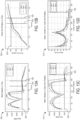
- FIG. 13A is a graph 500 of the speed of the motor 46 versus the time of motor operation according to some embodiments.
- the X-axis represents the time of motor operation in seconds, while the Y-axis represents speed of the motor 46 in RPM.
- the graph 500 shows the speed of the motor 46 for three different battery types (denoted in the key of the graph 500 as data 0, data 1, and data 2).
- the graph 500 includes a horizontal line 520 representing a target speed of the motor 46 before the crank arm assembly 54 hits one of the stop pins 102a, 102b.
- the time at which the crank arm assembly 54 will hit one of the stop pins 102a, 102b is represented on the graph 500 by a first vertical line 525 (for data 2) or a second vertical line 530 (for data 0 and data 1).
- FIG. 13B is a graph 505 of the position of the crank arm 76 versus the time of motor operation according to some embodiments.
- the X-axis represents the time of motor operation in seconds, while the Y-axis represents the crank arm 76 position in degrees (°).
- the graph 505 shows the crank arm 76 position for three different battery types (denoted in the key of the graph 505 as data 0, data 1, and data 2).
- the graph 505 includes a horizontal line 520 representing a target angle of the crank arm assembly 54 before the crank arm assembly 54 hits one of the stop pins 102a, 102b.
- the time at which the crank arm assembly 54 will hit one of the stop pins 102a, 102b is represented on the graph 505 by a first vertical line 525 (for data 2) or a second vertical line 530 (for data 0 and data 1).
- FIG. 13C is a graph 510 of the speed of the motor 46 versus the position of the crank arm 76 according to some embodiments.
- the X-axis represents the crank arm 76 position in °, while the Y-axis represents speed of the motor 46 in RPM.
- the graph 510 shows the speed of the motor 46 for three different battery types (denoted in the key of the graph 510 as data 0, data 1, and data 2).
- the graph 510 includes a horizontal line 520 representing a target speed of the motor 46 before the crank arm assembly 54 hits one of the stop pins 102a, 102b.
- the crank arm 76 position at which the crank arm assembly 54 will hit one of the stop pins 102a, 102b is represented on the graph 510 by a vertical line 535.
- FIG. 13D is a graph 515 of the current of the motor 46 versus the position of a crank arm 76 according to some embodiments.
- the X-axis represents the crank arm 76 position in °, while the Y-axis represents the current of the motor 46 in amps.
- the graph 515 shows the current of the motor 46 for three different battery types (denoted in the key of the graph 515 as data 0, data 1, and data 2).
- the crank arm 76 position at which the crank arm assembly 54 will hit one of the stop pins 102a, 102b is represented on the graph 515 by a vertical line 535.
- a power tool may use these graphs to determine a type of a battery pack electrically, mechanically, and/or communicatively coupled to the power tool, and therefore, the timing of one electrical cycle of the motor 46.
- a powered fastener driver comprising: a first cylinder; a first piston positioned within the first cylinder, the first piston being moveable between a top-dead-center position and at or near a bottom-dead-center position; a second cylinder in fluid communication with the first cylinder; a second piston positioned within the second cylinder, the second piston being moveable between a top-dead-center position and a bottom-dead-center position to initiate a fastener driving cycle; a drive blade coupled to the second piston for movement therewith; and a drive mechanism configured to drive the first piston between the top-dead-center position and at or near the bottom-dead-center position, the drive mechanism including a crank arm configured to rotate less than 360 degrees (°) for moving the first piston from at or near the bottom-dead-center position and the top-dead-center position and then back to at or near the bottom-dead-center position to complete the fastener driving cycle.
- the powered fastener driver further comprising a latch extending between the drive mechanism and the drive blade, wherein the latch is movable between a locked position, in which the latch engages the drive blade to secure the second piston in the top-dead-center position, and an unlocked position, in which the latch disengages the drive blade so the second piston is able to move between the top-dead-center position to the bottom-dead-center position.
- the powered fastener driver further comprising a biasing member configured to bias the latch towards the locked position, wherein the latch includes a recess aligned with the drive blade when the latch is in the unlocked position.
- the powered fastener driver wherein the drive blade includes a slot configured to receive a portion of the latch when the latch is in the locked position.
- the powered fastener driver wherein the drive mechanism includes a cam coupled for co-rotation with the crank arm.
- the powered fastener driver wherein the crank arm includes a stop surface configured to engage a fixed stop on a housing of the powered fastener driver both prior to and following completion of the fastener driving cycle.
- the powered fastener driver wherein a rotational speed of the crank arm is reduced before contact with the fixed stop to prevent shearing of the fixed stop.
- the powered fastener driver wherein the second piston is driven from the top-dead-center position to the bottom-dead-center position in response to the movement of the first piston.
- the powered fastener driver further comprising a back-pressure adjustment mechanism in communication with the second cylinder, the back-pressure adjustment mechanism configured to adjust a volumetric flow rate of air exhausted from the second cylinder by the second piston during the fastener driving cycle.
- the powered fastener driver wherein the back-pressure adjustment mechanism includes a basket rotatably supported within a housing of the powered fastener driver, and wherein the basket includes an opening that is selectively aligned with a window formed in the housing to adjust an effective size of the window, and therefore the volumetric flow rate of air exhausted from the second cylinder by the second piston during the fastener driving cycle.
- the powered fastener driver further comprising a check door that is movable between an open position, in which a second window in the housing is opened to permit atmospheric air to enter the second cylinder via the basket in response to the second piston moving from the bottom-dead-center position toward the top-dead-center position, and a closed position, in which the second window is closed and atmospheric air is prevented from exiting the second cylinder via the basket in response to the second piston moving from the top-dead-center position toward the bottom-dead-center position.
- a powered fastener driver comprising a first cylinder; a first piston positioned within the first cylinder, the first piston being moveable between a top-dead-center position and at or near a bottom-dead-center position; a second cylinder in fluid communication with the first cylinder; a second piston positioned within the second cylinder, the second piston being moveable between a top-dead-center position and a bottom-dead-center position to initiate a fastener driving cycle; a drive blade coupled to the second piston for movement therewith; and a drive mechanism configured to drive the first piston between the top-dead-center position and at or near the bottom-dead-center position, the drive mechanism including a crank arm having a stop surface configured to engage a fixed stop on a housing of the powered fastener driver both prior to and following completion of the fastener driving cycle.
- the powered fastener driver wherein a rotational speed of the crank arm is reduced before contact with the fixed stop to prevent shearing of the fixed stop.
- crank arm rotates in a range from 250° to 350° when moving the first piston from at or near the bottom-dead-center position to the top-dead-center position.
- the powered fastener driver wherein the drive mechanism includes a cam coupled for co-rotation with the crank arm, and wherein the cam includes a finger radially extending from a hub of the cam, which defines the stop surface.
- a powered fastener driver comprising a first cylinder; a first piston positioned within the first cylinder, the first piston being moveable between a top-dead-center position and at or near a bottom-dead-center position; a second cylinder in fluid communication with the first cylinder; a second piston positioned within the second cylinder, the second piston being moveable between a top-dead-center position and a bottom-dead-center position to initiate a fastener driving cycle; a drive blade coupled to the second piston for movement therewith; a drive mechanism configured to drive the first piston between the top-dead-center position and at or near the bottom-dead-center position to complete the fastener driving cycle; and a back-pressure adjustment mechanism in communication with the second cylinder, the back-pressure adjustment mechanism configured to adjust a volumetric flow rate of air exhausted from the second cylinder by the second piston during the fastener driving cycle.
- the powered fastener driver wherein the back-pressure adjustment mechanism includes a basket rotatably supported within a housing of the powered fastener driver, and wherein the basket includes an opening that is selectively aligned with a window formed in the housing to adjust an effective size of the window, and therefore the volumetric flow rate of air exhausted from the second cylinder by the second piston during the fastener driving cycle.
- the powered fastener driver further comprising a check door that is movable between an open position, in which a second window in the housing is opened to permit atmospheric air to enter the second cylinder via the basket in response to the second piston moving from the bottom-dead-center position toward the top-dead-center position, and a closed position, in which the second window is closed and atmospheric air is prevented from exiting the second cylinder via the basket in response to the second piston moving from the top-dead-center position toward the bottom-dead-center position.
- a method for controlling a motor of a power tool comprising electrically braking, by a controller, the motor at a first time; and applying a pulse-width modulated (PWM) signal to the motor, by the controller, at a second time; wherein the second time is determined by: determining, by the controller, a type of a battery pack electrically coupled to the power tool; and determining, by the controller, the second time based on the type of the battery pack.
- PWM pulse-width modulated
- electrically braking the motor includes electrically connecting a first lead of the motor to a second lead of the motor.
- a speed of the motor is reduced, by the controller, before a crank arm of the power tool reaches a fixed stop of the power tool.
- the method wherein the type of the battery pack is determined by: load testing the battery pack; and determining, by the controller, an internal resistance of the battery pack based on the load testing.
- load testing the battery pack includes driving a crank arm of the power tool against a fixed stop of the power tool, and measuring, by the controller, one or both of a voltage and a current of the battery pack.
- the method wherein the type of the battery pack is determined by: receiving a signal via a communication terminal of the battery pack, the signal indicative of the type of the battery pack.
- the method wherein the first time is determined based on the type of the battery pack.
- a method for controlling a motor of a powered fastener driver comprising: load testing a battery pack of the powered fastener driver by driving a crank arm against a fixed stop coupled to a housing of the powered fastener driver; determining, by a controller, an internal resistance of the battery pack by measuring one or both of a voltage and a current of the battery pack while driving the crank arm against the fixed stop; and determining, by the controller, a type of battery pack based on the determined internal resistance.
- the method further comprising determining, by the controller, a timing of one electrical cycle of the motor based on the determined type of the battery pack.
- determining the timing includes electrically braking, by the controller, the motor at a first time, and applying a pulse-width modulated (PWM) signal to the motor, by the controller, at a second time.
- PWM pulse-width modulated
- the method, wherein the second time is determined by:determining, by the controller, a type of the battery pack electrically coupled to the power tool; and determining, by the controller, the second time based on the type of the battery pack.
Landscapes
- Engineering & Computer Science (AREA)
- Mechanical Engineering (AREA)
- Physics & Mathematics (AREA)
- Fluid Mechanics (AREA)
- Portable Nailing Machines And Staplers (AREA)
- Details Of Spanners, Wrenches, And Screw Drivers And Accessories (AREA)
- Stopping Of Electric Motors (AREA)
- Control Of Direct Current Motors (AREA)
Abstract
Description
- This application claims priority to co-pending
U.S. Provisional Patent Application No. 63/222,639 filed on July 16, 2021 - The present disclosure relates to power tools, and more particularly to powered fastener drivers.
- There are various fastener drivers used to drive fasteners (e.g., nails, tacks, staples, etc.) into a workpiece known in the art. These fastener drivers operate utilizing various energy sources (e.g., compressed air generated by an air compressor, electrical energy, flywheel mechanisms) known in the art, but often these designs are met with power, size, and cost constraints.
- The disclosure provides, in one aspect, a powered fastener driver including a first cylinder, a first piston positioned within the first cylinder, the first piston being moveable between a top-dead-center position and at or near a bottom-dead-center position, a second cylinder in fluid communication with the first cylinder, a second piston positioned within the second cylinder, the second piston being moveable between a top-dead-center position and a bottom-dead-center position to initiate a fastener driving cycle, a drive blade coupled to the second piston for movement therewith, and a drive mechanism configured to drive the first piston between the top-dead-center position and at or near the bottom-dead-center position. The drive mechanism including a crank arm configured to rotate less than 360 degrees (°) for moving the first piston from at or near the bottom-dead-center position and the top-dead-center position and then back to at or near the bottom-dead-center position to complete the fastener driving cycle.
- The disclosure provides, in another aspect, a powered fastener driver including a first cylinder, a first piston positioned within the first cylinder, the first piston being moveable between a top-dead-center position and at or near a bottom-dead-center position, a second cylinder in fluid communication with the first cylinder, a second piston positioned within the second cylinder, the second piston being moveable between a top-dead-center position and a bottom-dead-center position to initiate a fastener driving cycle, a drive blade coupled to the second piston for movement therewith, and a drive mechanism configured to drive the first piston between the top-dead-center position and at or near the bottom-dead-center position. The drive mechanism including a crank arm having a stop surface configured to engage a fixed stop on a housing of the powered fastener driver both prior to and following completion of the fastener driving cycle.
- The disclosure provides, in another aspect, a powered fastener driver including a first cylinder, a first piston positioned within the first cylinder, the first piston being moveable between a top-dead-center position and at or near a bottom-dead-center position, a second cylinder in fluid communication with the first cylinder, a second piston positioned within the second cylinder, the second piston being moveable between a top-dead-center position and a bottom-dead-center position to initiate a fastener driving cycle, a drive blade coupled to the second piston for movement therewith, a drive mechanism configured to drive the first piston between the top-dead-center position and at or near the bottom-dead-center position to complete the fastener driving cycle, and a back-pressure adjustment mechanism in communication with the second cylinder, the back-pressure adjustment mechanism configured to adjust a volumetric flow rate of air exhausted from the second cylinder by the second piston during the fastener driving cycle.
- The disclosure provides, in another aspect, a method for controlling a motor of a power tool. The method comprising electrically braking, by a controller, the motor at a first time, and applying a pulse-width modulated (PWM) signal to the motor, by the controller, at a second time. The second time is determined by determining, by the controller, a type of a battery pack electrically coupled to the power tool, and determining, by the controller, the second time based on the type of the battery pack.
- The disclosure provides, in another aspect, a method for controlling a motor of a powered fastener driver. The method comprising load testing a battery pack of the powered fastener driver by driving a crank arm against a fixed stop coupled to a housing of the powered fastener driver, determining, by a controller, an internal resistance of the battery pack by measuring one or both of a voltage and a current of the battery pack while driving the crank arm against the fixed stop, and determining, by the controller, a type of battery pack based on the determined internal resistance.
- Other aspects of the disclosure will become apparent by consideration of the detailed description and accompanying drawings.
-
-
FIG. 1 is a perspective view of a powered fastener driver in accordance with an embodiment of the disclosure. -
FIG. 2 is a cross-sectional view of a portion of the powered fastener driver ofFIG. 1 taken along line 2-2 inFIG. 1 , illustrating an onboard compressor. -
FIG. 3 is a perspective view of a portion of the powered fastener driver ofFIG. 1 with a portion of a cylinder removed to illustrate a crank arm assembly and a latch. -
FIG. 4 is an enlarged perspective view of a portion of the powered fastener driver FIG. 3A, illustrating the latch in a locked position. -
FIG. 5 is a perspective view of a portion of the powered fastener driver ofFIG. 1 with a portion of a cylinder removed to illustrate cylinder head forming a passage between a compressor cylinder and a driver cylinder of the onboard compressor. -
FIG. 6 is a top, perspective view of a portion of the crank arm assembly of the powered fastener driver ofFIG. 1 , illustrating a cam lobe formed on a cam of the crank arm assembly. -
FIG. 7 is a bottom, perspective view of the crank arm assembly of the powered fastener driver ofFIG. 1 , illustrating a finger and a hub formed on a crank arm of the crank arm assembly. -
FIG. 8 is a top, perspective view of a structural housing of the powered fastener driver ofFIG. 1 , illustrating stop pins extending from an interior wall of the structural housing. -
FIG. 9 is a perspective view of the structural housing of the powered fastener driver ofFIG. 1 , illustrating a back-pressure adjustment mechanism and a check door. -
FIG. 10A is a partial perspective view of the structural housing of the powered fastener driver ofFIG. 1 , illustrating the check door in a closed position. -
FIG. 10B is a partial perspective view of the structural housing of the powered fastener driver ofFIG. 1 , illustrating the check door in an open position. -
FIG. 11 is a block diagram of a power tool system including a power tool and a battery pack according to embodiments described herein. -
FIG. 12 is a flow chart of a method for controlling the motor of a power tool according to embodiments described herein. -
FIG. 13A is a graph of the speed of the motor versus time, according to embodiments described herein. -
FIG. 13B is a graph of the position of a crank arm versus time of motor operation, according to embodiments described herein. -
FIG. 13C is a graph of the speed of the motor speed versus the position of the crank arm, according to embodiments described herein. -
FIG. 13D is a graph of the current of the motor versus the position of the crank arm, according to embodiments described herein. - Before any embodiments of the disclosure are explained in detail, it is to be understood that the present subject matter is not limited in its application to the details of construction and the arrangement of components set forth in the following description or illustrated in the following drawings. The present subject matter is capable of other embodiments and of being practiced or of being carried out in various ways.
- With reference to
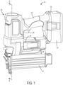
FIG. 1 , a poweredfastener driver 10 is operable to drive fasteners (e.g., nails, tacks, staples, etc.) held within amagazine 14 into a workpiece. The poweredfastener driver 10 includes an outer housing with ahandle portion 18, astructural housing 24, and a user-actuatedtrigger 26 mounted on thehandle portion 18. Notably, the poweredfastener driver 10 does not require an external source of air pressure, but rather the poweredfastener driver 10 includes an on-board air compressor 30. In this way, the weight and/or size of tool may be reduced. The on-board air compressor 30 is powered by a power source (e.g., a battery pack 20), coupled to a battery attachment portion 22 of the outer housing. - With reference to
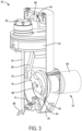
FIG. 2 , the poweredfastener driver 10 includes adrive blade 34 actuated by the on-board air compressor 30 to drive the fasteners into a workpiece. Thecompressor 30 includes acompressor cylinder 38, acompressor piston 42 in thecompressor cylinder 38, and adrive mechanism 44 that imparts reciprocating motion to thecompressor piston 42 to execute one or more consecutive fastener driving cycles. Thedrive mechanism 44 includes a motor 46 (e.g., a brushed or brushless DC motor), a transmission 50 (e.g., a multistage planetary transmission), and acrank arm assembly 54 that converts a rotational output of thetransmission 50 to a reciprocating input to thecompressor piston 42. Thefastener driver 10 also includes adrive cylinder 58 and adrive piston 62 slidably disposed in thedrive cylinder 58. - The
drive piston 62 is movable between a top-dead-center (TDC) position (FIG. 2 ) and a bottom-dead-center (BDC) position (e.g., when thedrive piston 62 is adjacent a stop member 60). Similarly, thecompressor piston 42 is moveable between a TDC position (e.g., when thecompressor piston 42 is adjacent a cylinder head 66) and a BDC position (e.g., when thecompressor piston 42 is adjacent the crank arm assembly 54), or close to a BDC position. The phrase "close to a BDC position" and/or "near BDC" as described herein, refers to a position within about 5 % to 25 % of reaching an absolute BDC, as thecrank arm assembly 54 may rotate less than 360° in some cases. In this way, thecompressor position 42 may not fully reach BDC. In the illustrated embodiment, thedrive cylinder 58 further includes a stop member 60 (e.g., a resilient bumper) positioned to engage and absorb energy from thedrive piston 62 when thedrive piston 62 reaches the BDC position. - As shown in
FIGS. 2 and5 , thesmaller drive cylinder 58 may extend into and/or within thelarger compressor cylinder 38 such that thecompressor piston 42 may surround theentire drive cylinder 58. By nesting the drive cylinder 58 (e.g., at least partially nested, fully nested, and/or the like) within thecompression cylinder 38, the size and/or weight of thefastener driver 10 may be advantageously reduced for improved handling, manufacturability, and/or the like. In this way, thefastener driver 10 may be easier for users to operate, and result in reduced user fatigue. Thedrive cylinder 58 and thecompression cylinder 38 are in fluid communication by way of a passage 64 (see e.g.,FIGS. 3 and5 ). Thepassage 64 allows for the transmission of air and, therefore, air pressure between the twocylinders cylinder head 66 is coupled to a distal end (e.g., an upper end) of thecompression cylinder 38. Thecylinder head 66 may include a plurality of apertures that define thepassage 64, which allows for continuous fluid communication between the twocylinders passage 64 may be devoid of a valve, in some cases. In some embodiments, thecompression cylinder 38 may be in continuous fluid communication such there is no selection or adjustment possible (e.g., thedrive cylinder 58 and thecompression cylinder 38 are always connected in an unchanging way). - As shown in
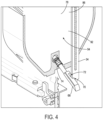
FIGS. 3 and4 , thepowered fastener driver 10 may additionally include alatch 68 supported within thestructural housing 24, which extends between thedrive mechanism 44 and thedrive blade 34. Thelatch 68 is movable between a locked position, in which thelatch 68 engages thedrive blade 34 to secure thedrive piston 62 in the TDC position, and an unlocked position, in which thelatch 68 disengages thedrive blade 34 so thedrive piston 62 is able to move from the TDC position to the BDC position to perform a fastener driving operation. In the illustrated embodiment, thedrive blade 34 includes aslot 70, and a biasingmember 74 configured to bias thelatch 68 towards the locked position. - The
latch 68 may further include a recess 72. When thelatch 68 is in the unlocked position, the recess 72 is aligned with thedrive blade 34. When thelatch 68 is in the locked position, theslot 70 formed in thedrive blade 34 is configured to receive a portion of thelatch 68 to restrict movement of thedrive blade 34. When thecrank arm assembly 54 moves thecompressor piston 42 towards the TDC position, thecrank arm assembly 54 moves thelatch 68 from the locked position to the unlocked position, which releases thedrive blade 34 and initiates a fastener driving operation. - As shown in
FIGS. 3 ,4 , and6 , thecrank arm assembly 54 includes acrank arm 76 with aneccentric pin 78 and a connectingrod 80 pivotably coupled to thepin 78 at one end and a piston pin 82 (FIG. 2 ) at an opposite end. With reference toFIG. 7 , thecrank arm 76 includes ahub 84 coupled for co-rotation with an output shaft of the transmission 50 (e.g., by a key and keyway arrangement). With reference toFIG. 6 , thecrank arm assembly 54 also includes acam 86 coupled for co-rotation with thecrank arm 76. Thecam 86 includes afirst side 88, asecond side 90 opposite thefirst side 88, and acam lobe 92 formed on thefirst side 88. In the illustrated embodiment, thecam lobe 92 is formed as a protrusion on thefirst side 88 of thecam 86 that extends in an axial direction and parallel with a rotational axis of thecrank arm 76 andcam 86. As explained in further detail below, one end of thelatch 68 is biased against thefirst side 88 of thecam 86, resulting in sliding movement between thelatch 68 and thecam 86 as thecam 86 rotates. As thelatch 68 slides up thecam lobe 92, thelatch 68 is moved towards the unlocked position. In this regard, thelatch 68 behaves as a follower in response to rotation of thecam 86. - The
crank arm assembly 54 is configured such that thecrank arm 76 and thecam 86 may be configured to rotate less than 360° to execute a complete fastener driving cycle. It should be appreciated that a complete fastener driving cycle may be defined as thecompressor piston 42 starting at a position near the BDC position, moving to the TDC position, and finishing at a position near the BDC position, while thedrive piston 62 starts at TDC position, moves to the BDC position when thecompressor piston 42 reaches the TDC position, and finishes in the TDC position. For thecompressor piston 42 to execute the complete fastener driving cycle, thecrank arm assembly 54 rotates less than 360°. - To initiate a subsequent compete fastener driving cycle, the rotation of the
crank arm assembly 54 is reversed by themotor 46. In the illustrated embodiment, thecrank arm 76 andcam 86 rotate approximately 292° during a complete fastener driving cycle. In other embodiments, thecrank arm 76 andcam 86 may rotate in a range from 250° to 350°. To accomplish this, themotor 46 rotates thecrank arm 76 andcam 86 alternately in a clockwise and a counterclockwise manner (e.g., clockwise then counterclockwise) to complete consecutive fastener driving cycles. - Now with reference to
FIG. 8 , thestructural housing 24 includes a pair of fixed stops or stop structures (stoppins structural housing 24 adjacent thecrank arm 76. And, as shown inFIG. 7 , thecrank arm 76 includes a finger 98 extending radially outward from thehub 84 on thesecond side 90 of thecam 86. The stop pins 102a, 102b are positioned such that opposite sides of the finger 98, respectively, can engage the stop pins 102a, 102b at the start and the end of each fastener driving cycle to form a hard stop. In the illustrated embodiment, the stop pins 102a, 102b are formed of rigid material (e.g., steel, aluminum, rigid plastic, and/or the like). In other embodiments, the stop pins 102a, 102b may be formed of a resilient material (e.g., rubber, elastomer, and/or the like). In the illustrated embodiment, the stop pins 102a, 102b and the width of the finger 98 define the angular range through which thecrank arm 76 is able to rotate, as described above. - As shown in
FIGS. 8-10B , thefastener driver 10 includes a back-pressure adjustment mechanism 106 supported within thestructural housing 24. The back-pressure adjustment mechanism 106 is configured to vary the amount of air exhausted from thedrive cylinder 58 beneath the drive piston 62 (i.e., on a side of thedrive piston 62 opposite the cylinder head 66) during a fastener driving cycle. Because thefastener driver 10 may not include any pressure valves, the pressure of compressed air developed within thecompressor cylinder 38 is the same and at a maximum value for each fastener driving cycle. - As such, the back-
pressure adjustment mechanism 106 can selectively increase or decrease the amount of air exhausted from thedrive cylinder 58 beneath thedrive piston 62 as thedrive piston 62 moves from the TDC position to the BDC position, thus either reducing or increasing, respectively, the back pressure acting on thedrive piston 62 during a fastener driving cycle. In this way, the force acting on thedrive piston 62 may be increased or decreased for driving different sizes of fasteners (e.g., 16 gauge nails, 18 gauge nails, 1 inch, 2 inch, and/or the like) to appropriate distances within a workpiece to make thefastener driver 10 suitable for use in a variety of different fastening applications. - The back-
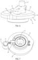
pressure adjustment mechanism 106 may include abasket 108 rotatably supported within thestructural housing 24, anadjustment member 110 extending from thebasket 108 through thestructural housing 24, and anopening 112 formed in thebasket 108 to expose a central bore within thebasket 108. Theopening 112 in thebasket 108 selectively aligns with awindow 114 formed in thestructural housing 24 which, in turn, is in fluid communication with the external atmosphere. Rotation of the basket 108 (e.g., via the adjustment member 110), adjusts the positioning of theopening 112 relative to thewindow 114, and thus the effective cross-sectional area of theopening 112 that is exposed to the atmosphere. - Adjusting the size of the exposed
opening 112, therefore, adjusts the volumetric flow rate of air that is exhausted from thedrive cylinder 58 beneath thedrive piston 62, through the exposedopening 112 andwindow 114. For example, reducing the size of the exposedopening 112 reduces the flow rate of air that can be exhausted through theopening 112, which creates a larger back-pressure acting against thedrive piston 62 and thus reduces the net force acting on thedrive piston 62 during a fastener driving cycle. Increasing the size of the exposedopening 112 increases the amount of air that can be exhausted through theopening 112, which creates a smaller back-pressure acting against thedrive piston 62 and thus increases the net force acting on thedrive piston 62 during a fastener driving cycle. - With continued reference to
FIGS. 9 ,10A, and 10B ,fastener driver 10 also includes acheck door 116 and a biasing member 118 (e.g., a torsion spring) that biases thecheck door 116 towards a closed position (FIG. 10A ), which blocks the flow rate of air through a second window 120 (FIG. 10B ) of thebasket 108. In the closed position, the second window 120 is closed and atmospheric air is prevented from exiting thedrive cylinder 58 via thebasket 108 in response to thedrive piston 62 moving from the TDC position toward the BDC position. Thecheck door 116 is positioned adjacent the back-pressure adjustment mechanism 106 and is movable to an open position where the second window 120 in thebasket 108 is opened to permit atmospheric air to enter thedrive cylinder 58 via thebasket 108 in response to thedrive piston 62 moving from the BDC position toward the TDC position. More specifically, during the movement of thedrive piston 62 from the BDC position toward the TDC position, a vacuum is created within thedrive cylinder 58 beneath thedrive piston 62 that pulls thecheck door 116 to the open position. - When the
check door 116 is in the open position, theentire opening 112 of thebasket 108 may be exposed to the atmosphere (via the first andsecond windows 114, 120 in the structural housing 24) so replacement air may enter thedrive cylinder 58 beneath thedrive piston 62. Once thedrive piston 62 is returned the TDC position, the vacuum acting on thecheck door 116 to hold thecheck door 116 in the open position dissipates, permitting thespring 118 to rebound and return thecheck door 116 to its closed position, thereby closing the second window 120, and resetting thedriver 10 for a subsequent fastener driving cycle. As thedrive piston 62 and thedrive blade 34 return to the TDC position, the biasingmember 74 also urges thelatch 68 into engagement with theslot 70 of thedrive blade 34, which locks thedrive blade 34 in a position for the subsequent fastener driving cycle. - At the beginning of a fastener driving cycle, the
latch 68 maintains thedrive piston 62 in the TDC position, while thecompressor piston 42 is in the BDC position. One side of the finger 98 on thecrank arm 76 is engaged with, for example, thestop pin 102a. When the operator actuates thetrigger 26, themotor 46 is activated to rotate thecrank arm 76 in a first rotational direction toward thestop pin 102a to confirm that the finger 98 is engaged with thestop pin 102a. This ensures thecrank arm 76 is in a starting position at the beginning of a fastener driving cycle. Themotor 46 is then rotated in an opposite direction to drive thecompressor piston 42 upward toward its TDC position by thecrank arm assembly 54. As thecompressor piston 42 travels upward, the air in thecompressor cylinder 38 and above thecompressor piston 42 is compressed, while thelatch 68 maintains thedrive piston 62 in the TDC position. - Once the
crank arm 76 andcam 86 reach a predetermined angular position coinciding with the TDC position of thecompressor piston 42, thelatch 68 is moved into its unlocked position by thecam 86, which releases thedrive blade 34 as described above. After thedrive blade 34 is released by thelatch 68, thedrive piston 62 is accelerated downward within thedrive cylinder 58 by the compressed air within thecompressor cylinder 38, which causes thedrive blade 34 to impact a fastener held in themagazine 14 and drive the fastener into a workpiece until thedrive piston 62 reaches thestop member 60 located at the BDC position within thedrive cylinder 58. - Upon the
drive piston 62 reaching its BDC position, one-half of the fastener driving cycle is complete, and thecompressor piston 42 is driven downwards towards the BDC position by themotor 46 and crankarm assembly 54 to complete the fastener driving cycle and ready thefastener driver 10 for a subsequent fastener driving cycle. As thecompressor piston 42 is driven through a retraction stroke (i.e., from the TDC position toward the BDC position), a vacuum is created within thecompressor cylinder 38 and thedrive cylinder 58, creating a pressure imbalance on thedrive piston 62 and a resultant upward force, causing thedrive piston 62 to return to its TDC position. During the movement of thedrive piston 62 to the TDC position, thecheck door 116 opens, which allows replacement air to enter thedrive cylinder 58 beneath thedrive piston 62 to facilitate return of thedrive piston 62 to the TDC position as described above. When thedrive piston 62 and thedrive blade 34 return to the TDC position, the biasingmember 74 urges thelatch 68 into theslot 70 of thedrive blade 34, which locks thedrive blade 34 in position for the subsequent fastener driving cycle. - In the illustrated embodiment, the rotational speed of the
motor 46 is decreased after the fastener driving operation occurs such that the opposite side of the finger 98 engages thestop pin stop pin crank arm assembly 54 allows acontrol system 300, described in more detail below, to initiate a timer-based control of themotor 46, which permits thefastener driver 10 to be sensorless. In other words, thefastener driver 10 does not use any position sensors to detect the position of thecompressor piston 42 or thedrive piston 62. Rather, for thecompressor piston 42 to execute the complete fastener driving cycle, thecrank arm assembly 54 rotates less than 360° (e.g., 292° in the illustrated embodiment). - To complete consecutive fastener driving cycles, the
motor 46 rotates thecrank arm 76 andcam 86 alternately in a clockwise and a counterclockwise manner (e.g., clockwise then counterclockwise). For example, a timer may be used to set a timer duration for the complete fastener driving operation. Thecontrol system 300 brakes themotor 46 at a first time (e.g., to prevent shearing of thestop pin crank arm 76 engages thestop pin crank arm 76 is stopped by thestop pin motor 46 is stalled (e.g., still receives power but does not rotate) until a remainder of the timer duration is reached (e.g., a third time is reached). As such, this ensures thecrank arm assembly 54 is positioned adjacent thestop pin -
FIG. 11 is a block diagram of acontrol system 300 of thepowered fastener driver 10. In other embodiments, thecontrol system 300 may be used with other power tools. Thecontrol system 300 may include acontroller 305, as well as other components not pictured inFIG. 11 , for example amotor 46, a solenoid, or other mechanical and/or electrical components described above. Thecontroller 305 may include aprocessing unit 310 comprising acontrol unit 315, anarithmetic logic unit 320, and one ormore registers 325. Thecontroller 305 may further include amemory 330 consisting ofprogram storage 335 and/ordata storage 340. Thememory 330 may be flash memory, random access memory, solid state memory, another type of memory, or a combination of these types. Thecontroller 305 may further include one ormore input units 345 and/oroutput units 350
The battery pack 355 may include astack 360 consisting of one or more battery cells 365. In some embodiments, the one or more battery cells 365 are electrically connected to each other in a series-type manner. In other embodiments, the one or more battery cells 365 are electrically connected to each other in a parallel-type manner. In still other embodiments, the one or more battery cells 365 are electrically connected to each other in a combination of a series-type and a parallel-type manner. The battery pack 355 may further include abattery controller 370 consisting of a battery processor 375 and abattery memory 380. The battery pack 355 may further include apositive battery terminal 385 and anegative battery terminal 390. Thepositive battery terminal 385 and thenegative battery terminal 390 may be configured to electrically and/or mechanically couple to corresponding terminals of thepowered fastener driver 10. In some embodiments, the battery pack 355 includes acommunication terminal 395, which may be configured to electrically, mechanically, and/or communicatively couple to one or more communication terminals of thepowered fastener driver 10. - In some embodiments, such as the block diagram of
FIG. 11 , the one or more battery cells 365 are connected to thebattery controller 370. Thebattery controller 370 controls the power delivered to thepositive battery terminal 385 and the negative battery terminal 390 (for example, via control of a discharge field-effect transistor (FET), a charge FET, and/or other FETs located within the battery pack). In some embodiments, thebattery pack controller 370 controls the power by allowing or prohibiting power. Additionally, in some embodiments, thebattery pack controller 370 controls the power by allowing a percentage of power generated by the one or more battery cells 365 to be output. In some embodiments, the amount of power delivered between thebattery terminals -
FIG. 12 is a flowchart illustrating amethod 400 for controlling a motor (e.g., the motor 46) of a power tool (e.g., the powered fastener driver 10), according to some embodiments. It should be understood that the order of the steps disclosed in themethod 400 could vary. For example, additional steps may be added to the process and not all of the steps may be required, or steps shown in one order may occur in a second order. Upon receiving a signal to begin an operation of the power tool, themethod 400 begins. Themethod 400 includes electrically controlling, by thecontroller 305, themotor 46 to drive the crank arm assembly 54 (BLOCK 405). In some embodiments, themotor 46 drives thecrank arm assembly 54 in a first direction. In some embodiments, thecontroller 305 may executeBLOCK 405 followingBLOCK 408. - The
method 400 further includes determining, by thecontroller 305, whether a battery pack electrically, mechanically, and/or communicatively coupled to the power tool includes a communication terminal (BLOCK 408). If thecontroller 305 determines that the battery pack does not include a communication terminal, thecontroller 305 additionally includes load testing the battery pack by driving thecrank arm assembly 54 against astop pin method 400 further includes determining, by thecontroller 305 an internal resistance of the battery pack (BLOCK 415). Thecontroller 305 may determine the internal resistance by measuring a voltage and/or a current of the battery pack while driving thecrank arm assembly 54 against thestop pin method 400 then includes determining, by thecontroller 305, a type of battery pack based on the determined internal resistance (BLOCK 420). If thecontroller 305 determines that the battery pack does include a communication terminal (inBLOCK 410, themethod 400 includes determining, by thecontroller 305, a type of battery pack by receiving a signal from the battery pack communication terminal (BLOCK 425). - Once the type of the battery pack has been determined by either method (e.g., a first method (BLOCKS 410, 415, and 420) or a second method (BLOCK 425)) presented above, the
method 400 includes determining, by thecontroller 305, a timing of one electrical cycle of the motor 46 (coinciding with one fastener driving cycle of the fastener driver 10) based on the determined type of the battery pack (BLOCK 430). The one electrical cycle may be the time between when themotor 46 begins driving thecrank arm assembly 54 from a starting position to when thecrank arm assembly 54 hits one of the stop pins 102a, 102b. Based on the timing of the electrical cycle, themethod 400 determines a first time and a second time. - The
method 400 further includes electrically braking, by thecontroller 305, themotor 46 at the determined first time and a first duration (BLOCK 435). Electrically braking themotor 46 may include electrically shorting the lead wires of themotor 46 together for the determined duration. Themethod 400 further includes applying a series of voltage pulses, by thecontroller 305, to themotor 46 for a second duration starting at the determined second time (BLOCK 440). - For example, the voltage pulses may correspond to a duty cycle of a pulse-width modulated (PWM) signal. The braking of the motor 46 (at the first time and for the first duration) and the applying of the PWM signal (at the second time and for a portion of the second duration) may occur before the
crank arm assembly 54 reaches one of the stop pins 102a, 102b. In the illustrated embodiment, the PWM signal is continuously applied to themotor 46 after thecrank arm assembly 54 engages thestop pin motor 46 to stall. For example, the second duration where the PWM signal is applied to themotor 46 includes a time both prior to and after thecrank arm assembly 54 engages thestop pin crank arm assembly 54 is positioned adjacent thestop pin - In some embodiments, the
controller 305 causes themotor 46 to drive thecrank arm assembly 54 in a first direction in a first electrical cycle of themotor 46, wherein one electrical cycle is the time between when themotor 46 begins driving thecrank arm assembly 54 from a starting position to when thecrank arm assembly 54 hits one of the stop pins 102a, 102b. Thecontroller 305 may then cause themotor 46 to drive thecrank arm assembly 54 in a second direction, opposite the first direction, in a second electrical cycle of themotor 46. Themotor 46 may alternatively drive thecrank arm assembly 54 in this fashion in alternative cycles. For example, in the first, third, fifth, and so-on cycles, themotor 46 may drive thecrank arm assembly 54 in a clockwise direction, while in the second, fourth, sixth, and so-on cycles, themotor 46 may drive thecrank arm assembly 54 in a counterclockwise direction, or vice versa. - In some embodiments, the signal to begin the first electrical cycle of the
motor 46 may be based on an actuation of atrigger 26 or another switch of the power tool. Thecontroller 305 may wait to begin the second electrical cycle until a second actuation of thetrigger 26 or other switch occurs. In other embodiments, thecontroller 305 may begin the first electrical cycle in response to an actuation of atrigger 26 or another switch of the power tool. Thecontroller 305 may begin the second electrical cycle once the first cycle has completed and while thetrigger 26 or other switch remains actuated. -
FIG. 13A is agraph 500 of the speed of themotor 46 versus the time of motor operation according to some embodiments. The X-axis represents the time of motor operation in seconds, while the Y-axis represents speed of themotor 46 in RPM. Thegraph 500 shows the speed of themotor 46 for three different battery types (denoted in the key of thegraph 500 asdata 0,data 1, and data 2). Thegraph 500 includes ahorizontal line 520 representing a target speed of themotor 46 before thecrank arm assembly 54 hits one of the stop pins 102a, 102b. The time at which thecrank arm assembly 54 will hit one of the stop pins 102a, 102b is represented on thegraph 500 by a first vertical line 525 (for data 2) or a second vertical line 530 (fordata 0 and data 1). -
FIG. 13B is agraph 505 of the position of thecrank arm 76 versus the time of motor operation according to some embodiments. The X-axis represents the time of motor operation in seconds, while the Y-axis represents thecrank arm 76 position in degrees (°). Thegraph 505 shows thecrank arm 76 position for three different battery types (denoted in the key of thegraph 505 asdata 0,data 1, and data 2). Thegraph 505 includes ahorizontal line 520 representing a target angle of thecrank arm assembly 54 before thecrank arm assembly 54 hits one of the stop pins 102a, 102b. The time at which thecrank arm assembly 54 will hit one of the stop pins 102a, 102b is represented on thegraph 505 by a first vertical line 525 (for data 2) or a second vertical line 530 (fordata 0 and data 1). -
FIG. 13C is agraph 510 of the speed of themotor 46 versus the position of thecrank arm 76 according to some embodiments. The X-axis represents thecrank arm 76 position in °, while the Y-axis represents speed of themotor 46 in RPM. Thegraph 510 shows the speed of themotor 46 for three different battery types (denoted in the key of thegraph 510 asdata 0,data 1, and data 2). Thegraph 510 includes ahorizontal line 520 representing a target speed of themotor 46 before thecrank arm assembly 54 hits one of the stop pins 102a, 102b. Thecrank arm 76 position at which thecrank arm assembly 54 will hit one of the stop pins 102a, 102b is represented on thegraph 510 by avertical line 535. -
FIG. 13D is agraph 515 of the current of themotor 46 versus the position of acrank arm 76 according to some embodiments. The X-axis represents thecrank arm 76 position in °, while the Y-axis represents the current of themotor 46 in amps. Thegraph 515 shows the current of themotor 46 for three different battery types (denoted in the key of thegraph 515 asdata 0,data 1, and data 2). Thecrank arm 76 position at which thecrank arm assembly 54 will hit one of the stop pins 102a, 102b is represented on thegraph 515 by avertical line 535. A power tool according to embodiments described herein may use these graphs to determine a type of a battery pack electrically, mechanically, and/or communicatively coupled to the power tool, and therefore, the timing of one electrical cycle of themotor 46. - Although the present subject matter has been described in detail with reference to certain preferred embodiments, variations and modifications exist within the scope of one or more independent aspects of the present subject matter as described.
- A powered fastener driver comprising: a first cylinder; a first piston positioned within the first cylinder, the first piston being moveable between a top-dead-center position and at or near a bottom-dead-center position; a second cylinder in fluid communication with the first cylinder; a second piston positioned within the second cylinder, the second piston being moveable between a top-dead-center position and a bottom-dead-center position to initiate a fastener driving cycle; a drive blade coupled to the second piston for movement therewith; and a drive mechanism configured to drive the first piston between the top-dead-center position and at or near the bottom-dead-center position, the drive mechanism including a crank arm configured to rotate less than 360 degrees (°) for moving the first piston from at or near the bottom-dead-center position and the top-dead-center position and then back to at or near the bottom-dead-center position to complete the fastener driving cycle.
- The powered fastener driver, further comprising a latch extending between the drive mechanism and the drive blade, wherein the latch is movable between a locked position, in which the latch engages the drive blade to secure the second piston in the top-dead-center position, and an unlocked position, in which the latch disengages the drive blade so the second piston is able to move between the top-dead-center position to the bottom-dead-center position.
- The powered fastener driver, further comprising a biasing member configured to bias the latch towards the locked position, wherein the latch includes a recess aligned with the drive blade when the latch is in the unlocked position.
- The powered fastener driver, wherein the drive blade includes a slot configured to receive a portion of the latch when the latch is in the locked position.
- The powered fastener driver, wherein the drive mechanism includes a cam coupled for co-rotation with the crank arm. The powered fastener driver, wherein the cam includes a lobe configured to engage the latch to move the latch from the locked position toward the unlocked position.
- The powered fastener driver, wherein the crank arm includes a stop surface configured to engage a fixed stop on a housing of the powered fastener driver both prior to and following completion of the fastener driving cycle. The powered fastener driver, wherein a rotational speed of the crank arm is reduced before contact with the fixed stop to prevent shearing of the fixed stop.
- The powered fastener driver, wherein the second piston is driven from the top-dead-center position to the bottom-dead-center position in response to the movement of the first piston.
- The powered fastener driver, further comprising a back-pressure adjustment mechanism in communication with the second cylinder, the back-pressure adjustment mechanism configured to adjust a volumetric flow rate of air exhausted from the second cylinder by the second piston during the fastener driving cycle.
- The powered fastener driver, wherein the back-pressure adjustment mechanism includes a basket rotatably supported within a housing of the powered fastener driver, and wherein the basket includes an opening that is selectively aligned with a window formed in the housing to adjust an effective size of the window, and therefore the volumetric flow rate of air exhausted from the second cylinder by the second piston during the fastener driving cycle. The powered fastener driver, further comprising a check door that is movable between an open position, in which a second window in the housing is opened to permit atmospheric air to enter the second cylinder via the basket in response to the second piston moving from the bottom-dead-center position toward the top-dead-center position, and a closed position, in which the second window is closed and atmospheric air is prevented from exiting the second cylinder via the basket in response to the second piston moving from the top-dead-center position toward the bottom-dead-center position.
- A powered fastener driver comprising a first cylinder; a first piston positioned within the first cylinder, the first piston being moveable between a top-dead-center position and at or near a bottom-dead-center position; a second cylinder in fluid communication with the first cylinder; a second piston positioned within the second cylinder, the second piston being moveable between a top-dead-center position and a bottom-dead-center position to initiate a fastener driving cycle; a drive blade coupled to the second piston for movement therewith; and a drive mechanism configured to drive the first piston between the top-dead-center position and at or near the bottom-dead-center position, the drive mechanism including a crank arm having a stop surface configured to engage a fixed stop on a housing of the powered fastener driver both prior to and following completion of the fastener driving cycle.
- The powered fastener driver, wherein a rotational speed of the crank arm is reduced before contact with the fixed stop to prevent shearing of the fixed stop.
- The powered fastener driver, wherein the crank arm rotates in a range from 250° to 350° when moving the first piston from at or near the bottom-dead-center position to the top-dead-center position.
- The powered fastener driver, wherein the drive mechanism includes a cam coupled for co-rotation with the crank arm, and wherein the cam includes a finger radially extending from a hub of the cam, which defines the stop surface.
- A powered fastener driver comprising a first cylinder; a first piston positioned within the first cylinder, the first piston being moveable between a top-dead-center position and at or near a bottom-dead-center position; a second cylinder in fluid communication with the first cylinder; a second piston positioned within the second cylinder, the second piston being moveable between a top-dead-center position and a bottom-dead-center position to initiate a fastener driving cycle; a drive blade coupled to the second piston for movement therewith; a drive mechanism configured to drive the first piston between the top-dead-center position and at or near the bottom-dead-center position to complete the fastener driving cycle; and a back-pressure adjustment mechanism in communication with the second cylinder, the back-pressure adjustment mechanism configured to adjust a volumetric flow rate of air exhausted from the second cylinder by the second piston during the fastener driving cycle.
- The powered fastener driver, wherein the back-pressure adjustment mechanism includes a basket rotatably supported within a housing of the powered fastener driver, and wherein the basket includes an opening that is selectively aligned with a window formed in the housing to adjust an effective size of the window, and therefore the volumetric flow rate of air exhausted from the second cylinder by the second piston during the fastener driving cycle. The powered fastener driver, further comprising a check door that is movable between an open position, in which a second window in the housing is opened to permit atmospheric air to enter the second cylinder via the basket in response to the second piston moving from the bottom-dead-center position toward the top-dead-center position, and a closed position, in which the second window is closed and atmospheric air is prevented from exiting the second cylinder via the basket in response to the second piston moving from the top-dead-center position toward the bottom-dead-center position.
- A method for controlling a motor of a power tool, the method comprising electrically braking, by a controller, the motor at a first time; and applying a pulse-width modulated (PWM) signal to the motor, by the controller, at a second time; wherein the second time is determined by: determining, by the controller, a type of a battery pack electrically coupled to the power tool; and determining, by the controller, the second time based on the type of the battery pack.
- The method, wherein electrically braking the motor includes electrically connecting a first lead of the motor to a second lead of the motor. The method, wherein a speed of the motor is reduced, by the controller, before a crank arm of the power tool reaches a fixed stop of the power tool.
- The method, wherein the type of the battery pack is determined by: load testing the battery pack; and determining, by the controller, an internal resistance of the battery pack based on the load testing. The method, wherein load testing the battery pack includes driving a crank arm of the power tool against a fixed stop of the power tool, and measuring, by the controller, one or both of a voltage and a current of the battery pack.
- The method, wherein the type of the battery pack is determined by: receiving a signal via a communication terminal of the battery pack, the signal indicative of the type of the battery pack.
- The method, wherein the first time is determined based on the type of the battery pack.
- A method for controlling a motor of a powered fastener driver, the method comprising: load testing a battery pack of the powered fastener driver by driving a crank arm against a fixed stop coupled to a housing of the powered fastener driver; determining, by a controller, an internal resistance of the battery pack by measuring one or both of a voltage and a current of the battery pack while driving the crank arm against the fixed stop; and determining, by the controller, a type of battery pack based on the determined internal resistance.
- The method, further comprising determining, by the controller, a timing of one electrical cycle of the motor based on the determined type of the battery pack. The method, wherein determining the timing includes electrically braking, by the controller, the motor at a first time, and applying a pulse-width modulated (PWM) signal to the motor, by the controller, at a second time. The method, wherein the second time is determined by:determining, by the controller, a type of the battery pack electrically coupled to the power tool; and determining, by the controller, the second time based on the type of the battery pack.
- The method, wherein a speed of the motor is reduced, by the controller, before the crank arm reaches the fixed stop.
- Various feature of the invention are set forth in the following claims.
- The preferred aspects of the present disclosure may be summarized as follows:
- 1. A powered fastener driver comprising:
- a first cylinder;
- a first piston positioned within the first cylinder, the first piston being moveable between a top-dead-center position and at or near a bottom-dead-center position;
- a second cylinder in fluid communication with the first cylinder;
- a second piston positioned within the second cylinder, the second piston being moveable between a top-dead-center position and a bottom-dead-center position to initiate a fastener driving cycle;
- a drive blade coupled to the second piston for movement therewith; and
- a drive mechanism configured to drive the first piston between the top-dead-center position and at or near the bottom-dead-center position, the drive mechanism including a crank arm configured to rotate less than 360 degrees (°) for moving the first piston from at or near the bottom-dead-center position and the top-dead-center position and then back to at or near the bottom-dead-center position to complete the fastener driving cycle.
- 2. The powered fastener driver of
aspect 1, further comprising a latch extending between the drive mechanism and the drive blade, wherein the latch is movable between a locked position, in which the latch engages the drive blade to secure the second piston in the top-dead-center position, and an unlocked position, in which the latch disengages the drive blade so the second piston is able to move between the top-dead-center position to the bottom-dead-center position. - 3. The powered fastener driver of
aspect 2, further comprising a biasing member configured to bias the latch towards the locked position, wherein the latch includes a recess aligned with the drive blade when the latch is in the unlocked position. - 4. The powered fastener driver of aspect 3, wherein the drive blade includes a slot configured to receive a portion of the latch when the latch is in the locked position.
- 5. The powered fastener driver of
aspect 2, wherein the drive mechanism includes a cam coupled for co-rotation with the crank arm. - 6. The powered fastener driver of aspect 5, wherein the cam includes a lobe configured to engage the latch to move the latch from the locked position toward the unlocked position.
- 7. The powered fastener driver of
aspect 1, wherein the crank arm includes a stop surface configured to engage a fixed stop on a housing of the powered fastener driver both prior to and following completion of the fastener driving cycle. - 8. The powered fastener driver of aspect 7, wherein a rotational speed of the crank arm is reduced before contact with the fixed stop to prevent shearing of the fixed stop.
- 9. The powered fastener driver of
aspect 1, wherein the second piston is driven from the top-dead-center position to the bottom-dead-center position in response to the movement of the first piston. - 10. The powered fastener driver of
aspect 1, further comprising a back-pressure adjustment mechanism in communication with the second cylinder, the back-pressure adjustment mechanism configured to adjust a volumetric flow rate of air exhausted from the second cylinder by the second piston during the fastener driving cycle. - 11. The powered fastener driver of
aspect 10, wherein the back-pressure adjustment mechanism includes a basket rotatably supported within a housing of the powered fastener driver, and wherein the basket includes an opening that is selectively aligned with a window formed in the housing to adjust an effective size of the window, and therefore the volumetric flow rate of air exhausted from the second cylinder by the second piston during the fastener driving cycle. - 12. The powered fastener driver of aspect 11, further comprising a check door that is movable between an open position, in which a second window in the housing is opened to permit atmospheric air to enter the second cylinder via the basket in response to the second piston moving from the bottom-dead-center position toward the top-dead-center position, and a closed position, in which the second window is closed and atmospheric air is prevented from exiting the second cylinder via the basket in response to the second piston moving from the top-dead-center position toward the bottom-dead-center position.
- 13. A powered fastener driver comprising:
- a first cylinder;
- a first piston positioned within the first cylinder, the first piston being moveable between a top-dead-center position and at or near a bottom-dead-center position;
- a second cylinder in fluid communication with the first cylinder;
- a second piston positioned within the second cylinder, the second piston being moveable between a top-dead-center position and a bottom-dead-center position to initiate a fastener driving cycle;
- a drive blade coupled to the second piston for movement therewith; and
- a drive mechanism configured to drive the first piston between the top-dead-center position and at or near the bottom-dead-center position, the drive mechanism including a crank arm having a stop surface configured to engage a fixed stop on a housing of the powered fastener driver both prior to and following completion of the fastener driving cycle.
- 14. The powered fastener driver of aspect 13, wherein a rotational speed of the crank arm is reduced before contact with the fixed stop to prevent shearing of the fixed stop.
- 15. The powered fastener driver of aspect 13, wherein the crank arm rotates in a range from 250° to 350° when moving the first piston from at or near the bottom-dead-center position to the top-dead-center position.
- 16. The powered fastener driver of aspect 13, wherein the drive mechanism includes a cam coupled for co-rotation with the crank arm, and wherein the cam includes a finger radially extending from a hub of the cam, which defines the stop surface.
- 17. A powered fastener driver comprising:
- a first cylinder;
- a first piston positioned within the first cylinder, the first piston being moveable between a top-dead-center position and at or near a bottom-dead-center position;
- a second cylinder in fluid communication with the first cylinder;
- a second piston positioned within the second cylinder, the second piston being moveable between a top-dead-center position and a bottom-dead-center position to initiate a fastener driving cycle;
- a drive blade coupled to the second piston for movement therewith;
- a drive mechanism configured to drive the first piston between the top-dead-center position and at or near the bottom-dead-center position to complete the fastener driving cycle; and
- a back-pressure adjustment mechanism in communication with the second cylinder, the back-pressure adjustment mechanism configured to adjust a volumetric flow rate of air exhausted from the second cylinder by the second piston during the fastener driving cycle.
- 18. The powered fastener driver of aspect 17, wherein the back-pressure adjustment mechanism includes a basket rotatably supported within a housing of the powered fastener driver, and wherein the basket includes an opening that is selectively aligned with a window formed in the housing to adjust an effective size of the window, and therefore the volumetric flow rate of air exhausted from the second cylinder by the second piston during the fastener driving cycle.
- 19. The powered fastener driver of
aspect 18, further comprising a check door that is movable between an open position, in which a second window in the housing is opened to permit atmospheric air to enter the second cylinder via the basket in response to the second piston moving from the bottom-dead-center position toward the top-dead-center position, and a closed position, in which the second window is closed and atmospheric air is prevented from exiting the second cylinder via the basket in response to the second piston moving from the top-dead-center position toward the bottom-dead-center position. - 20. A method for controlling a motor of a power tool, the method comprising:
- electrically braking, by a controller, the motor at a first time; and
- applying a pulse-width modulated (PWM) signal to the motor, by the controller, at a second time;
- wherein the second time is determined by:
- determining, by the controller, a type of a battery pack electrically coupled to the power tool; and
- determining, by the controller, the second time based on the type of the battery pack.
- 21. The method of
aspect 20, wherein electrically braking the motor includes electrically connecting a first lead of the motor to a second lead of the motor. - 22. The method of
aspect 20, wherein a speed of the motor is reduced, by the controller, before a crank arm of the power tool reaches a fixed stop of the power tool. - 23. The method of
aspect 20, wherein the type of the battery pack is determined by:- load testing the battery pack; and
- determining, by the controller, an internal resistance of the battery pack based on the load testing.
- 24. The method of aspect 23, wherein load testing the battery pack includes driving a crank arm of the power tool against a fixed stop of the power tool, and measuring, by the controller, one or both of a voltage and a current of the battery pack.
- 25. The method of
aspect 20, wherein the type of the battery pack is determined by:
receiving a signal via a communication terminal of the battery pack, the signal indicative of the type of the battery pack. - 26. The method of
aspect 20, wherein the first time is determined based on the type of the battery pack. - 27. A method for controlling a motor of a powered fastener driver, the method comprising:
- load testing a battery pack of the powered fastener driver by driving a crank arm against a fixed stop coupled to a housing of the powered fastener driver;
- determining, by a controller, an internal resistance of the battery pack by measuring one or both of a voltage and a current of the battery pack while driving the crank arm against the fixed stop; and
- determining, by the controller, a type of battery pack based on the determined internal resistance.
- 28. The method of aspect 27, further comprising determining, by the controller, a timing of one electrical cycle of the motor based on the determined type of the battery pack.
- 29. The method of aspect 28, wherein determining the timing includes electrically braking, by the controller, the motor at a first time, and applying a pulse-width modulated (PWM) signal to the motor, by the controller, at a second time.
- 30. The method of aspect 29, wherein the second time is determined by:
- determining, by the controller, a type of the battery pack electrically coupled to the power tool; and
- determining, by the controller, the second time based on the type of the battery pack.
- 31. The method of aspect 27, wherein a speed of the motor is reduced, by the controller, before the crank arm reaches the fixed stop.
Claims (7)
- A method for controlling a motor of a power tool, the method comprising:electrically braking, by a controller, the motor at a first time; andapplying a pulse-width modulated (PWM) signal to the motor, by the controller, at a second time;wherein the second time is determined by:determining, by the controller, a type of a battery pack electrically coupled to the power tool; anddetermining, by the controller, the second time based on the type of the battery pack.
- The method of claim 1, wherein electrically braking the motor includes electrically connecting a first lead of the motor to a second lead of the motor.
- The method of claim 1, wherein a speed of the motor is reduced, by the controller, before a crank arm of the power tool reaches a fixed stop of the power tool.
- The method of claim 1, wherein the type of the battery pack is determined by:load testing the battery pack; anddetermining, by the controller, an internal resistance of the battery pack based on the load testing.
- The method of claim 4, wherein load testing the battery pack includes driving a crank arm of the power tool against a fixed stop of the power tool, and measuring, by the controller, one or both of a voltage and a current of the battery pack.
- The method of claim 1, wherein the type of the battery pack is determined by:
receiving a signal via a communication terminal of the battery pack, the signal indicative of the type of the battery pack. - The method of claim 1, wherein the first time is determined based on the type of the battery pack.
Applications Claiming Priority (2)
| Application Number | Priority Date | Filing Date | Title |
|---|---|---|---|
| US202163222639P | 2021-07-16 | 2021-07-16 | |
| EP22185034.0A EP4119298B1 (en) | 2021-07-16 | 2022-07-14 | Powered fastener driver |
Related Parent Applications (2)
| Application Number | Title | Priority Date | Filing Date |
|---|---|---|---|
| EP22185034.0A Division-Into EP4119298B1 (en) | 2021-07-16 | 2022-07-14 | Powered fastener driver |
| EP22185034.0A Division EP4119298B1 (en) | 2021-07-16 | 2022-07-14 | Powered fastener driver |
Publications (3)
| Publication Number | Publication Date |
|---|---|
| EP4249172A2 true EP4249172A2 (en) | 2023-09-27 |
| EP4249172A3 EP4249172A3 (en) | 2023-12-06 |
| EP4249172B1 EP4249172B1 (en) | 2024-09-18 |
Family
ID=82608341
Family Applications (4)
| Application Number | Title | Priority Date | Filing Date |
|---|---|---|---|
| EP23186896.9A Active EP4249172B1 (en) | 2021-07-16 | 2022-07-14 | Method for controlling a motor of a power tool |
| EP23186892.8A Active EP4286101B1 (en) | 2021-07-16 | 2022-07-14 | Powered fastener driver |
| EP23186899.3A Active EP4286102B1 (en) | 2021-07-16 | 2022-07-14 | Method for controlling a motor of a power fastener driver |
| EP22185034.0A Active EP4119298B1 (en) | 2021-07-16 | 2022-07-14 | Powered fastener driver |
Family Applications After (3)
| Application Number | Title | Priority Date | Filing Date |
|---|---|---|---|
| EP23186892.8A Active EP4286101B1 (en) | 2021-07-16 | 2022-07-14 | Powered fastener driver |
| EP23186899.3A Active EP4286102B1 (en) | 2021-07-16 | 2022-07-14 | Method for controlling a motor of a power fastener driver |
| EP22185034.0A Active EP4119298B1 (en) | 2021-07-16 | 2022-07-14 | Powered fastener driver |
Country Status (5)
| Country | Link |
|---|---|
| US (2) | US11850714B2 (en) |
| EP (4) | EP4249172B1 (en) |
| CN (1) | CN218698480U (en) |
| CA (1) | CA3167425A1 (en) |
| MX (1) | MX2022008721A (en) |
Families Citing this family (1)
| Publication number | Priority date | Publication date | Assignee | Title |
|---|---|---|---|---|
| EP4417370A1 (en) * | 2023-02-17 | 2024-08-21 | Nanjing Chervon Industry Co., Ltd. | Nail gun |
Family Cites Families (130)
| Publication number | Priority date | Publication date | Assignee | Title |
|---|---|---|---|---|
| US317212A (en) | 1885-05-05 | Max eubin | ||
| US942163A (en) | 1909-12-07 | August Berner | Pneumatic power-hammer. | |
| US1072358A (en) | 1905-11-25 | 1913-09-02 | Pneumelectric Machine Company | Fluid-pressure-driven tool. |
| US1072367A (en) | 1912-05-08 | 1913-09-02 | Pneumelectric Machine Company | Double-compression reciprocating implement. |
| US1829609A (en) | 1929-05-06 | 1931-10-27 | Frank R Robinson | Pneumatic hammer |
| US3035268A (en) | 1959-10-05 | 1962-05-22 | Modernair Corp | Pneumatically-operated fastener driving machine |
| US3150488A (en) | 1961-11-22 | 1964-09-29 | Emmett L Haley | Power devices |
| DE1277166B (en) | 1963-04-27 | 1968-09-05 | Behrens Friedrich Joh | Device operated with compressed air for driving in nails, staples or the like. |
| GB1044288A (en) | 1964-09-17 | 1966-09-28 | Gen Wire Overseas Corp | Power devices suitable for operating hand tools |
| FR1414089A (en) | 1964-09-21 | 1965-10-15 | Gen Wire Overseas Corp | Motor device for hand tool |
| US3567098A (en) | 1966-12-23 | 1971-03-02 | Bostitch Div Of Textron | Fastener driving apparatus operable under pressure conditions greater than line pressure |
| GB1243472A (en) | 1969-03-15 | 1971-08-18 | Daiichi Kikai Seisakusho Co Lt | A free-piston type percussion device with an air pump |
| SE343784B (en) | 1969-11-07 | 1972-03-20 | Atlas Copco Ab | |
| SE371128B (en) | 1971-08-02 | 1974-11-11 | K Charlez | |
| JPS519199B2 (en) | 1972-04-03 | 1976-03-24 | ||
| US4192389A (en) | 1978-08-02 | 1980-03-11 | Boeing Commercial Airplane Company | Single impact rivet gun |
| DE2946387C2 (en) | 1979-11-16 | 1986-04-10 | Signode Corp., Glenview, Ill. | Pneumatically actuated driving tool |
| US4415110A (en) | 1981-08-17 | 1983-11-15 | Hunter C Lamont | LP Gas-operated impact tool |
| JPH0747270B2 (en) | 1986-09-13 | 1995-05-24 | 松下電工株式会社 | Battery powered nailer |
| DE3728454C2 (en) | 1987-08-26 | 1993-12-23 | Bosch Gmbh Robert | Pressurized impact device |
| DE3826213A1 (en) | 1988-08-02 | 1990-02-15 | Bosch Gmbh Robert | DRILLING HAMMER |
| US4913331A (en) | 1988-10-21 | 1990-04-03 | Hitachi Koki Company, Ltd. | Internal-combustion piston driving apparatus having a decompression channel |
| JP3676879B2 (en) | 1995-07-25 | 2005-07-27 | 株式会社マキタ | Fastener driving tool |
| US6158643A (en) | 1997-12-31 | 2000-12-12 | Porter-Cable Corporation | Internal combustion fastener driving tool piston and piston ring |
| US6231319B1 (en) | 1998-02-13 | 2001-05-15 | Matsushita Electric Industrial Co., Ltd. | Hermetic compressor |
| US6672498B2 (en) | 1999-09-17 | 2004-01-06 | Stanley Fastening Sytems Lp | Feed system for nailer |
| DE10033362A1 (en) | 2000-07-08 | 2002-01-17 | Hilti Ag | Electric hand tool with empty stroke shutdown |
| US6796475B2 (en) | 2000-12-22 | 2004-09-28 | Senco Products, Inc. | Speed controller for flywheel operated hand tool |
| DE60200127T2 (en) | 2001-03-07 | 2004-06-03 | Black & Decker Inc., Newark | hammer |
| US7494035B2 (en) | 2001-04-30 | 2009-02-24 | Black & Decker Inc. | Pneumatic compressor |
| US7225959B2 (en) | 2001-04-30 | 2007-06-05 | Black & Decker, Inc. | Portable, battery-powered air compressor for a pneumatic tool system |
| TW570864B (en) | 2001-05-17 | 2004-01-11 | Li-Jeng Jang | Portable pneumatic tool |
| US6705503B1 (en) | 2001-08-20 | 2004-03-16 | Tricord Solutions, Inc. | Electrical motor driven nail gun |
| US6604666B1 (en) | 2001-08-20 | 2003-08-12 | Tricord Solutions, Inc. | Portable electrical motor driven nail gun |
| US7032683B2 (en) | 2001-09-17 | 2006-04-25 | Milwaukee Electric Tool Corporation | Rotary hammer |
| US6874452B2 (en) | 2002-01-15 | 2005-04-05 | Joseph S. Adams | Resonant combustion chamber and recycler for linear motors |
| US20040232194A1 (en) | 2002-03-07 | 2004-11-25 | Pedicini Christopher S. | Enhanced electrical motor driven nail gun |
| DE10260704A1 (en) | 2002-12-23 | 2004-07-01 | Hilti Ag | Combustion-powered setting tool |
| CN1798954A (en) | 2003-06-12 | 2006-07-05 | 三索解决方案公司 | Portable electric driven compressed air gun |
| EP1704022A1 (en) | 2003-12-30 | 2006-09-27 | Poly Systems Pty Limited | Fastener driving tool |
| EP1773545A2 (en) | 2004-07-23 | 2007-04-18 | Gavin Beales | Nailer device |
| US6971567B1 (en) | 2004-10-29 | 2005-12-06 | Black & Decker Inc. | Electronic control of a cordless fastening tool |
| US20060180631A1 (en) | 2005-02-16 | 2006-08-17 | Chris Pedicini | Electric motor driven energy storage device for impacting |
| DE102005000061A1 (en) | 2005-05-18 | 2006-11-23 | Hilti Ag | Electrically operated tacker |
| TW200711799A (en) | 2005-06-29 | 2007-04-01 | Poly Systems Pty Ltd | A hand-held power tool |
| DE102005000107B4 (en) | 2005-08-25 | 2014-03-13 | Hilti Aktiengesellschaft | Pneumatically operated setting tool |
| US7419079B2 (en) | 2006-02-03 | 2008-09-02 | Basso Industry Corp. | Pneumatic tool |
| JP2007222989A (en) | 2006-02-23 | 2007-09-06 | Max Co Ltd | Drive piston holding structure in gas nailer |
| US20080078799A1 (en) | 2006-10-03 | 2008-04-03 | Wan-Fu Wen | Nail Gun with Electric Power Generating Unit |
| US8875969B2 (en) | 2007-02-09 | 2014-11-04 | Tricord Solutions, Inc. | Fastener driving apparatus |
| JP2008255813A (en) | 2007-04-02 | 2008-10-23 | Max Co Ltd | Gas internal combustion type nail driver |
| US8276798B2 (en) | 2007-06-21 | 2012-10-02 | Illinois Tool Works Inc. | Feeder mechanism retention device for fastener driving tool |
| US7984708B2 (en) | 2007-08-27 | 2011-07-26 | Impulse Solutions, Llc | Projectile launching apparatus |
| TWI379746B (en) | 2007-10-05 | 2012-12-21 | Senco Brands Inc | Fastener driving tool using a gas spring |
| JP5146734B2 (en) | 2008-01-15 | 2013-02-20 | 日立工機株式会社 | Fastener driving machine |
| DE102008000909A1 (en) | 2008-04-01 | 2009-10-08 | Hilti Aktiengesellschaft | Internal combustion setting device |
| JP5529855B2 (en) | 2008-05-21 | 2014-06-25 | ポリ・システムズ・プロプライエタリー・リミテッド | Tool for driving the fixture |
| JP5212713B2 (en) | 2008-09-05 | 2013-06-19 | 日立工機株式会社 | air compressor |
| US20100072248A1 (en) | 2008-09-19 | 2010-03-25 | Basso Industry Corp. | Nailing force-adjusting device for a pneumatic nail gun |
| EP2367660B1 (en) | 2008-12-24 | 2019-07-10 | Globalforce IP Limited | Actuation system |
| US7793811B1 (en) | 2009-02-25 | 2010-09-14 | Tricord Solutions, Inc. | Fastener driving apparatus |
| WO2011010634A1 (en) | 2009-07-24 | 2011-01-27 | 株式会社マキタ | Hammering tool |
| JP2012187640A (en) | 2009-07-24 | 2012-10-04 | Makita Corp | Hammering tool |
| JPWO2011010511A1 (en) | 2009-07-24 | 2012-12-27 | トリコード ソリューションズ,インコーポレイティド | Driving tool |
| DE102009041824A1 (en) | 2009-09-18 | 2011-03-24 | Hilti Aktiengesellschaft | Device for transmitting energy to a fastener |
| US8523035B2 (en) | 2009-11-11 | 2013-09-03 | Tricord Solutions, Inc. | Fastener driving apparatus |
| US20110180581A1 (en) | 2010-01-24 | 2011-07-28 | De Poan Pneumatic Corp. | Resetting and Driving Mechanism for Nail Driving Rod in Pneumatic Nailer having Embedded Air Compressor |
| US20120085226A1 (en) | 2010-10-08 | 2012-04-12 | Bradhart Products, Inc. | Gas Piston System Actuator Assembly for Rifle Automatic Ejection and Reload |
| US8079504B1 (en) | 2010-11-04 | 2011-12-20 | Tricord Solutions, Inc. | Fastener driving apparatus |
| JP5551050B2 (en) | 2010-11-24 | 2014-07-16 | 株式会社マキタ | Air compressor |
| US9050712B2 (en) | 2011-01-20 | 2015-06-09 | Black & Decker Inc. | Driving tool with internal air compressor |
| US8800834B2 (en) | 2011-05-11 | 2014-08-12 | Tricord Solutions, Inc. | Fastener driving apparatus |
| US9770818B2 (en) | 2011-10-03 | 2017-09-26 | Illinois Tool Works Inc. | Fastener driving tool with portable pressurized power source |
| US20140299646A1 (en) | 2011-10-13 | 2014-10-09 | Poly Systems Pty Ltd | Hand held power tool for driving fasteners |
| JP5800748B2 (en) | 2012-04-09 | 2015-10-28 | 株式会社マキタ | Driving tool |
| JP5800749B2 (en) * | 2012-04-09 | 2015-10-28 | 株式会社マキタ | Driving tool |
| JP5859372B2 (en) | 2012-04-27 | 2016-02-10 | 株式会社マキタ | Driving tool |
| JP2013233609A (en) | 2012-05-08 | 2013-11-21 | Makita Corp | Driving tool |
| JP5758841B2 (en) | 2012-05-08 | 2015-08-05 | 株式会社マキタ | Driving tool |
| DE102012210347A1 (en) | 2012-06-19 | 2013-12-19 | Hilti Aktiengesellschaft | Setting tool and control method |
| US8733610B2 (en) | 2012-08-21 | 2014-05-27 | Tricord Solutions, Inc. | Fastener driving apparatus |
| JP2014083601A (en) | 2012-10-19 | 2014-05-12 | Makita Corp | Driving tool |
| JP2014091196A (en) | 2012-11-05 | 2014-05-19 | Makita Corp | Driving tool |
| JP5921037B2 (en) | 2012-11-12 | 2016-05-24 | 株式会社マキタ | Driving tool |
| JP2014104533A (en) | 2012-11-27 | 2014-06-09 | Makita Corp | Driving tool |
| JP2014104534A (en) | 2012-11-27 | 2014-06-09 | Makita Corp | Driving tool |
| JP2014108495A (en) | 2012-12-03 | 2014-06-12 | Makita Corp | Driving tool |
| US9555530B2 (en) | 2013-06-20 | 2017-01-31 | Tricord Solutions, Inc. | Fastener driving apparatus |
| US8939341B2 (en) | 2013-06-20 | 2015-01-27 | Tricord Solutions, Inc. | Fastener driving apparatus |
| EP2826600A1 (en) | 2013-07-16 | 2015-01-21 | HILTI Aktiengesellschaft | Control method and hand tool machine |
| EP2826601A1 (en) | 2013-07-16 | 2015-01-21 | HILTI Aktiengesellschaft | Control method and hand tool machine |
| EP2826599A1 (en) | 2013-07-16 | 2015-01-21 | HILTI Aktiengesellschaft | Control method and hand tool machine |
| US9662777B2 (en) | 2013-08-22 | 2017-05-30 | Techtronic Power Tools Technology Limited | Pneumatic fastener driver |
| EP2851157A1 (en) | 2013-09-19 | 2015-03-25 | HILTI Aktiengesellschaft | Driving device with pneumatic storage |
| EP2851158A1 (en) | 2013-09-19 | 2015-03-25 | HILTI Aktiengesellschaft | Driving device with heated pneumatic reservoir |
| JP6100680B2 (en) | 2013-12-11 | 2017-03-22 | 株式会社マキタ | Driving tool |
| CA3146951A1 (en) | 2014-03-27 | 2015-10-01 | Techtronic Power Tools Technology Limited | Powered fastener driver and operating method thereof |
| JP6284417B2 (en) | 2014-04-16 | 2018-02-28 | 株式会社マキタ | Driving tool |
| WO2016174994A1 (en) | 2015-04-30 | 2016-11-03 | 日立工機株式会社 | Driving machine |
| CN204736190U (en) * | 2015-06-26 | 2015-11-04 | 张华定 | Nailer |
| CA2993187C (en) | 2015-07-23 | 2023-12-12 | Tricord Solutions, Inc. | Fastener driving apparatus |
| WO2017045972A1 (en) | 2015-09-14 | 2017-03-23 | Hilti Aktiengesellschaft | Fuel gas-fired driving-in tool with charging function |
| EP3141348A1 (en) | 2015-09-14 | 2017-03-15 | HILTI Aktiengesellschaft | Driving device powered by combustion gas with valve member |
| EP3181295A1 (en) | 2015-12-18 | 2017-06-21 | HILTI Aktiengesellschaft | Internal combustion operated driving tool |
| EP3184250A1 (en) | 2015-12-22 | 2017-06-28 | HILTI Aktiengesellschaft | Internal combustion gas operated driving tool |
| CN105818099B (en) | 2016-05-26 | 2017-11-17 | 杭州科龙电器工具股份有限公司 | Use the electric nail gun of gas spring |
| US20170361443A1 (en) | 2016-06-20 | 2017-12-21 | Black & Decker Inc. | Cylindrical Integrated Valve Assembly |
| US20180009097A1 (en) | 2016-07-06 | 2018-01-11 | Tti (Macao Commercial Offshore) Limited | Powered fastener driver |
| US20180207777A1 (en) | 2016-07-06 | 2018-07-26 | Tti (Macao Commercial Offshore) Limited | Powered fastener driver |
| CN206263884U (en) | 2016-11-07 | 2017-06-20 | 浙江三锋实业股份有限公司 | A kind of electronic air nail gun |
| CN108098694B (en) | 2016-11-25 | 2020-09-01 | 南京德朔实业有限公司 | Power tool |
| CN206614481U (en) | 2016-12-09 | 2017-11-07 | 南京德朔实业有限公司 | Ailing machine |
| CA3049715C (en) | 2017-01-09 | 2022-10-04 | Tricord Solutions, Inc. | Impacting apparatus |
| TWI744560B (en) | 2017-11-02 | 2021-11-01 | 鑽全實業股份有限公司 | Pneumatic nail gun and its firing pin device |
| US11110577B2 (en) | 2017-11-16 | 2021-09-07 | Milwaukee Electric Tool Corporation | Pneumatic fastener driver |
| CN207629980U (en) | 2017-12-22 | 2018-07-20 | 王家宏 | Integral electric air pressure nailing gun |
| CN107914242A (en) | 2017-12-22 | 2018-04-17 | 王家宏 | Integral electric air pressure nailing gun |
| CN108527255B (en) | 2018-03-10 | 2021-03-26 | 南京腾亚精工科技股份有限公司 | Nailing power adjustable mosquito nail gun |
| CN208614700U (en) * | 2018-08-25 | 2019-03-19 | 张华定 | A kind of adjustable nailing rifle |
| CN110900524B (en) | 2018-09-18 | 2023-07-14 | 苏州宝时得电动工具有限公司 | Nail gun, control system of nail gun and start-stop control method |
| CA3204017A1 (en) | 2018-10-17 | 2020-04-23 | Kyocera Senco Industrial Tools, Inc. | Working cylinder for power tool with piston lubricating system |
| CN109623736B (en) | 2018-12-17 | 2022-11-08 | 浙江普莱得电器股份有限公司 | Nail gun with reliable work |
| CN209648625U (en) | 2018-12-17 | 2019-11-19 | 浙江普莱得电器有限公司 | A kind of simple nail gun of structure |
| CN109623737B (en) | 2018-12-17 | 2022-06-21 | 浙江普莱得电器股份有限公司 | Stable nail rifle of nailing |
| CN109571373B (en) | 2019-01-30 | 2023-08-18 | 浙江荣鹏气动工具股份有限公司 | Locking device on firing pin of double-cylinder electric nailing gun |
| TWI808135B (en) | 2019-03-06 | 2023-07-11 | 鑽全實業股份有限公司 | electric nail gun |
| CN210550947U (en) | 2019-07-05 | 2020-05-19 | 朱益民 | Cylinder and nailing tool |
| US11819989B2 (en) | 2020-07-07 | 2023-11-21 | Techtronic Cordless Gp | Powered fastener driver |
| CN112677109A (en) | 2020-12-28 | 2021-04-20 | 台州市钉霸电动工具有限公司 | Pneumatic nailing gun |
| CN112828827A (en) | 2021-02-02 | 2021-05-25 | 台州市钉霸电动工具有限公司 | Pneumatic nailing gun with adjustable nailing force |
-
2022
- 2022-07-12 CA CA3167425A patent/CA3167425A1/en active Pending
- 2022-07-13 US US17/863,942 patent/US11850714B2/en active Active
- 2022-07-14 EP EP23186896.9A patent/EP4249172B1/en active Active
- 2022-07-14 EP EP23186892.8A patent/EP4286101B1/en active Active
- 2022-07-14 EP EP23186899.3A patent/EP4286102B1/en active Active
- 2022-07-14 MX MX2022008721A patent/MX2022008721A/en unknown
- 2022-07-14 EP EP22185034.0A patent/EP4119298B1/en active Active
- 2022-07-15 CN CN202221839688.9U patent/CN218698480U/en active Active
-
2023
- 2023-12-05 US US18/530,135 patent/US20240100671A1/en active Pending
Also Published As
| Publication number | Publication date |
|---|---|
| EP4119298B1 (en) | 2024-06-05 |
| EP4286101B1 (en) | 2024-09-18 |
| US11850714B2 (en) | 2023-12-26 |
| US20240100671A1 (en) | 2024-03-28 |
| EP4286101A1 (en) | 2023-12-06 |
| CA3167425A1 (en) | 2023-01-16 |
| EP4119298A2 (en) | 2023-01-18 |
| EP4119298A3 (en) | 2023-05-03 |
| EP4119298C0 (en) | 2024-06-05 |
| MX2022008721A (en) | 2023-01-17 |
| EP4286102B1 (en) | 2024-08-28 |
| EP4286102A1 (en) | 2023-12-06 |
| EP4249172A3 (en) | 2023-12-06 |
| CN218698480U (en) | 2023-03-24 |
| US20230020670A1 (en) | 2023-01-19 |
| EP4249172B1 (en) | 2024-09-18 |
Similar Documents
| Publication | Publication Date | Title |
|---|---|---|
| US20240100671A1 (en) | Powered fastener driver | |
| US10569403B2 (en) | Gas spring fastener driver | |
| CA2969392C (en) | Gas spring fastener driver | |
| WO2011010511A1 (en) | Hammering tool | |
| JP2011025362A (en) | Driving tool | |
| JPWO2011010512A1 (en) | Driving tool | |
| US11654540B2 (en) | Powered fastener driver | |
| CN217097624U (en) | Gas spring driven fastener driver | |
| WO2016174995A1 (en) | Driving machine | |
| US20230311285A1 (en) | Powered fastener driver having split gear box | |
| US20240131670A1 (en) | Pusher mechanism for powered fastener driver | |
| US20240030784A1 (en) | Firmware control providing a soft stop on compression drive nailer | |
| US12083659B2 (en) | Unbalanced roller on lifting mechanism | |
| US20240149416A1 (en) | Fastener delivery mechanism for a fastener driver | |
| CN115716257A (en) | Nail gun | |
| JPH0557633A (en) | Driving tool | |
| JP2003260671A (en) | Method and device of screwing |
Legal Events
| Date | Code | Title | Description |
|---|---|---|---|
| PUAI | Public reference made under article 153(3) epc to a published international application that has entered the european phase |
Free format text: ORIGINAL CODE: 0009012 |
|
| STAA | Information on the status of an ep patent application or granted ep patent |
Free format text: STATUS: THE APPLICATION HAS BEEN PUBLISHED |
|
| AC | Divisional application: reference to earlier application |
Ref document number: 4119298 Country of ref document: EP Kind code of ref document: P |
|
| AK | Designated contracting states |
Kind code of ref document: A2 Designated state(s): AL AT BE BG CH CY CZ DE DK EE ES FI FR GB GR HR HU IE IS IT LI LT LU LV MC MK MT NL NO PL PT RO RS SE SI SK SM TR |
|
| REG | Reference to a national code |
Ref country code: DE Ref legal event code: R079 Ref document number: 602022006260 Country of ref document: DE Free format text: PREVIOUS MAIN CLASS: B25C0001000000 Ipc: B25C0001040000 Ref country code: DE Ref legal event code: R079 Free format text: PREVIOUS MAIN CLASS: B25C0001000000 Ipc: B25C0001040000 |
|
| PUAL | Search report despatched |
Free format text: ORIGINAL CODE: 0009013 |
|
| AK | Designated contracting states |
Kind code of ref document: A3 Designated state(s): AL AT BE BG CH CY CZ DE DK EE ES FI FR GB GR HR HU IE IS IT LI LT LU LV MC MK MT NL NO PL PT RO RS SE SI SK SM TR |
|
| RIC1 | Information provided on ipc code assigned before grant |
Ipc: B25C 1/00 20060101ALI20231031BHEP Ipc: B25C 1/06 20060101ALI20231031BHEP Ipc: B25C 1/04 20060101AFI20231031BHEP |
|
| STAA | Information on the status of an ep patent application or granted ep patent |
Free format text: STATUS: REQUEST FOR EXAMINATION WAS MADE |
|
| 17P | Request for examination filed |
Effective date: 20240115 |
|
| RBV | Designated contracting states (corrected) |
Designated state(s): AL AT BE BG CH CY CZ DE DK EE ES FI FR GB GR HR HU IE IS IT LI LT LU LV MC MK MT NL NO PL PT RO RS SE SI SK SM TR |
|
| RIC1 | Information provided on ipc code assigned before grant |
Ipc: B25C 1/00 20060101ALI20240326BHEP Ipc: B25C 1/06 20060101ALI20240326BHEP Ipc: B25C 1/04 20060101AFI20240326BHEP |
|
| GRAP | Despatch of communication of intention to grant a patent |
Free format text: ORIGINAL CODE: EPIDOSNIGR1 |
|
| STAA | Information on the status of an ep patent application or granted ep patent |
Free format text: STATUS: GRANT OF PATENT IS INTENDED |
|
| GRAS | Grant fee paid |
Free format text: ORIGINAL CODE: EPIDOSNIGR3 |
|
| INTG | Intention to grant announced |
Effective date: 20240716 |
|
| GRAA | (expected) grant |
Free format text: ORIGINAL CODE: 0009210 |
|
| STAA | Information on the status of an ep patent application or granted ep patent |
Free format text: STATUS: THE PATENT HAS BEEN GRANTED |
|
| AC | Divisional application: reference to earlier application |
Ref document number: 4119298 Country of ref document: EP Kind code of ref document: P |
|
| AK | Designated contracting states |
Kind code of ref document: B1 Designated state(s): AL AT BE BG CH CY CZ DE DK EE ES FI FR GB GR HR HU IE IS IT LI LT LU LV MC MK MT NL NO PL PT RO RS SE SI SK SM TR |
|
| REG | Reference to a national code |
Ref country code: GB Ref legal event code: FG4D |