EP4246993A2 - Folded camera structure with an extended light-folding-element scanning range - Google Patents
Folded camera structure with an extended light-folding-element scanning range Download PDFInfo
- Publication number
- EP4246993A2 EP4246993A2 EP23190556.3A EP23190556A EP4246993A2 EP 4246993 A2 EP4246993 A2 EP 4246993A2 EP 23190556 A EP23190556 A EP 23190556A EP 4246993 A2 EP4246993 A2 EP 4246993A2
- Authority
- EP
- European Patent Office
- Prior art keywords
- opfe
- digital camera
- degrees
- folded digital
- actuator
- Prior art date
- Legal status (The legal status is an assumption and is not a legal conclusion. Google has not performed a legal analysis and makes no representation as to the accuracy of the status listed.)
- Pending
Links
- 230000003287 optical effect Effects 0.000 claims abstract description 17
- 230000006641 stabilisation Effects 0.000 claims abstract description 5
- 238000011105 stabilization Methods 0.000 claims abstract description 5
- 238000000034 method Methods 0.000 claims description 10
- 230000003321 amplification Effects 0.000 description 5
- 238000003199 nucleic acid amplification method Methods 0.000 description 5
- 238000004088 simulation Methods 0.000 description 3
- 239000010935 stainless steel Substances 0.000 description 3
- 229910001220 stainless steel Inorganic materials 0.000 description 3
- 229910000583 Nd alloy Inorganic materials 0.000 description 2
- 101150026889 VAMP2 gene Proteins 0.000 description 2
- 102000003786 Vesicle-associated membrane protein 2 Human genes 0.000 description 2
- 229910045601 alloy Inorganic materials 0.000 description 2
- 239000000956 alloy Substances 0.000 description 2
- KPLQYGBQNPPQGA-UHFFFAOYSA-N cobalt samarium Chemical compound [Co].[Sm] KPLQYGBQNPPQGA-UHFFFAOYSA-N 0.000 description 2
- 230000000694 effects Effects 0.000 description 2
- 238000005516 engineering process Methods 0.000 description 2
- 230000005484 gravity Effects 0.000 description 2
- 238000005259 measurement Methods 0.000 description 2
- 238000010137 moulding (plastic) Methods 0.000 description 2
- 229910001172 neodymium magnet Inorganic materials 0.000 description 2
- 229910000938 samarium–cobalt magnet Inorganic materials 0.000 description 2
- 230000001133 acceleration Effects 0.000 description 1
- 230000004075 alteration Effects 0.000 description 1
- 229910052751 metal Inorganic materials 0.000 description 1
- 239000002184 metal Substances 0.000 description 1
- 230000002265 prevention Effects 0.000 description 1
- 238000004804 winding Methods 0.000 description 1
Images


Classifications
-
- G—PHYSICS
- G02—OPTICS
- G02B—OPTICAL ELEMENTS, SYSTEMS OR APPARATUS
- G02B27/00—Optical systems or apparatus not provided for by any of the groups G02B1/00 - G02B26/00, G02B30/00
- G02B27/64—Imaging systems using optical elements for stabilisation of the lateral and angular position of the image
-
- H—ELECTRICITY
- H04—ELECTRIC COMMUNICATION TECHNIQUE
- H04N—PICTORIAL COMMUNICATION, e.g. TELEVISION
- H04N23/00—Cameras or camera modules comprising electronic image sensors; Control thereof
- H04N23/60—Control of cameras or camera modules
- H04N23/68—Control of cameras or camera modules for stable pick-up of the scene, e.g. compensating for camera body vibrations
- H04N23/682—Vibration or motion blur correction
- H04N23/685—Vibration or motion blur correction performed by mechanical compensation
-
- H—ELECTRICITY
- H04—ELECTRIC COMMUNICATION TECHNIQUE
- H04N—PICTORIAL COMMUNICATION, e.g. TELEVISION
- H04N23/00—Cameras or camera modules comprising electronic image sensors; Control thereof
- H04N23/45—Cameras or camera modules comprising electronic image sensors; Control thereof for generating image signals from two or more image sensors being of different type or operating in different modes, e.g. with a CMOS sensor for moving images in combination with a charge-coupled device [CCD] for still images
-
- G—PHYSICS
- G02—OPTICS
- G02B—OPTICAL ELEMENTS, SYSTEMS OR APPARATUS
- G02B13/00—Optical objectives specially designed for the purposes specified below
- G02B13/001—Miniaturised objectives for electronic devices, e.g. portable telephones, webcams, PDAs, small digital cameras
- G02B13/0055—Miniaturised objectives for electronic devices, e.g. portable telephones, webcams, PDAs, small digital cameras employing a special optical element
- G02B13/0065—Miniaturised objectives for electronic devices, e.g. portable telephones, webcams, PDAs, small digital cameras employing a special optical element having a beam-folding prism or mirror
-
- H—ELECTRICITY
- H04—ELECTRIC COMMUNICATION TECHNIQUE
- H04N—PICTORIAL COMMUNICATION, e.g. TELEVISION
- H04N23/00—Cameras or camera modules comprising electronic image sensors; Control thereof
- H04N23/50—Constructional details
- H04N23/55—Optical parts specially adapted for electronic image sensors; Mounting thereof
-
- H—ELECTRICITY
- H04—ELECTRIC COMMUNICATION TECHNIQUE
- H04N—PICTORIAL COMMUNICATION, e.g. TELEVISION
- H04N23/00—Cameras or camera modules comprising electronic image sensors; Control thereof
- H04N23/58—Means for changing the camera field of view without moving the camera body, e.g. nutating or panning of optics or image sensors
Definitions
- Embodiments disclosed herein relate in general to digital cameras and in particular to thin multi-aperture zoom digital cameras.
- Personal electronic devices such as smartphones having two back cameras (also referred to as “dual-cameras” or “dual-aperture cameras”) are known and available commercially.
- the two back cameras have respective lenses with different fixed focal lengths and respective image sensors (or simply “sensors”) operated to capture image data (or “image”). Even though each lens/sensor combination is aligned to look in the same direction, each will capture an image of the same scene with a different field of view (FOV).
- FOV field of view
- a Tele camera with adjustable FOV T for maximizing zooming capabilities is disclosed for example in commonly owned and invented PCT patent application PCT/IB2016/057366 titled "Dual-aperture zoom digital camera with automatic adjustable tele field of view".
- the adjustable FOV involves scanning enabled by a step motor.
- step motors have been replaced by voice coil motor (VCM) technology.
- VCM actuation is used for autofocus (AF) and ⁇ or optical image stabilization (OIS).
- AF autofocus
- OIS optical image stabilization
- known VCM actuator technology in particular as used in folded cameras, may have a limited scanning range and a given VCM actuator may perform only OIS, which requires motion compensation in a very limited range.
- VCM actuation mechanism for adjustable FOV T with extended scanning range.
- VCM actuation mechanism for adjustable FOV T with extended scanning range that can simultaneously support scanning in an extended range and OIS.
- Embodiments disclosed herein relate to VCM actuators for Tele folded cameras with adjustable FOV T , such as the camera described in PCT/IB2016/057366.
- the disclosed actuators are designed to maximize zooming and scanning capabilities.
- Some exemplary disclosed embodiments also allow OIS in parallel with image scanning.
- an actuator for rotating an OPFE over a scanning range in which OPFE position is controlled by a non-accurate position sensing mechanism that determines an allowable jitter limit comprising: an actuated sub-assembly rigidly coupled to the OPFE and having two hinges that define a rotation axis, and a stationary sub-assembly having two housings, wherein each housing is nested in a respective hinge of the stationary sub-assembly to form a housing-hinge pair, wherein a center-of-mass of the actuated sub-assembly is positioned to coincide with the rotation axis to limit jitter arising from the OPFE being rotated to and stopped at a given OPFE position to be no larger than an allowable limit.
- each housing-hinge pair has a degree of friction designed to assist in limiting the jitter arising from the OPFE being rotated to and stopped at a given OPFE position to be no larger than the allowable limit.
- the stationary sub-assembly includes a position sensor for sensing the given OPFE position.
- the position sensor includes a Hall bar sensing element.
- the scanning range is larger than ⁇ 1.5 degrees around a rest position of the OPFE.
- the scanning range is at least ⁇ 5 degrees around the rest position of the OPFE.
- the scanning range is up to ⁇ 20 degrees around the rest position of the OPFE.
- FIGS. 1A -D illustrate in various views an actuator 100 of a rotational voice coil motor (VCM), according to an example of the presently disclosed subject matter.
- Actuator 100 enables an extended OPFE scanning range relative to the needs of other systems that rotate an OPFE for OIS (where the rotation is typically of ⁇ 1 degree, as e.g. the system described in co-assigned PCT patent application PCT/IB2016/052179 ) and enables as well adjustment of FOV T .
- FIG. 1A shows actuator 100 in an isometric view
- FIG. 1B shows actuator 100 from a back view
- FIG. 1C shows actuator 100 in an exploded view.
- Actuator 100 enables rotation (in an angle referred to as " ⁇ ") of an OPFE 102 (for example a prism or mirror) around a single axis 104 (i.e. around for example the X axis in the coordinate system shown and used in all figures), as described below.
- Axis 104 may also be referred to as "rotation axis".
- the extended range of ⁇ may be for example in the range of 10 degrees to 40 degrees (or ⁇ 5 degrees to ⁇ 20 degrees around an initial "rest" position).
- ⁇ 20 degrees or ⁇ 10 degrees around the rest position
- known designs in which the OPFE is rotated (tilted) for OIS purposes only enable a limited rotation range of 0.5 to 3 degrees or ⁇ 0.25 to ⁇ 1.5 degrees around the rest position.
- OPFE 102 is held in an optical element holder (or simply "holder") 106 , which may be made, for example by plastic molding, fit to the shape of OPFE 102.
- An actuation magnet 108 is fixedly attached (e.g. glued) to optical element holder 106 from below (negative Z direction in FIG. 1B ).
- a sensing magnet 110 is fixedly attached (e.g. glued) to holder 106 on one side of the holder in a groove 112.
- Two hinges 114a and 114b are fixedly attached (e.g. glued) to holder 106 on two sides.
- Hinges 114a and 114b are made for example of a hard metal, e.g. stainless steel.
- actuated sub-assembly The assembly of OPFE 102 , optical element holder 106 , actuation magnet 108 , sensing magnet 110 , and hinges 114a and 114b will be referred to henceforth as "actuated sub-assembly" 116.
- Actuator 100 further includes a base 118 , made for example of plastic, and two housings 120a and 120b also made for example of plastic, housings 120a and 120b fixedly attached (e.g. glued) to base 118.
- base 118 and either one or both of housings 120a and 120b may be molded as a single part.
- housing 120a and ⁇ or housing 120b may include several parts which are assembled and e.g. glued only during the actuator assembly process.
- Base 118 and housings 120a and 120b form a "stationary sub-assembly" 122.
- Stationary sub-assembly 122 further includes a Hall bar sensing element 126 and a coil 124 , both described below.
- Actuated sub-assembly 116 is positioned inside stationary sub-assembly 122 such that hinges 114a and 114b are positioned inside housings 120a and 120b respectively. Hinges 114a and 114b are concentric and lie on axis 104 (parallel to the X axis in the figures).
- the mechanical structure described allows the rotation of actuated sub-assembly 116 and of OPFE 102 around axis 104.
- the plastic moldings of base 118 and/or optical element holder 106 may be used as a mechanical stopper for actuated sub-assembly 116 to prevent motion beyond ⁇ degrees.
- axis 104 is positioned through the center-of-mass of actuated sub-assembly 116.
- the "mass” includes elements 102,106, 108, 110, 114a and 114b.
- an external rotation of actuator 100 (caused e.g. by a user rotating a device including the actuator) will not cause a relative rotation between actuated sub-assembly 116 and stationary sub-assembly 122.
- Actuator 100 further includes a wound coil 124 , for example of a stadium shape, typically with a few tens of windings (e.g. in a not limiting range of 50-250) and with a typical resistance of 10-30 ohm.
- Coil 124 is located below magnet 108 such that nominally their centers overlap when the actuated sub-assembly is at rest.
- Magnet 108 can be for example a permanent magnet, made from a neodymium alloy (e.g. Nd 2 Fe 14 B) or a samarium-cobalt alloy (e.g. SmCo 5 ). Magnet 108 can be fabricated (e.g.
- Coil 124 is connected to external current driving circuit (not shown), the driving circuit capable of sending input currents to coil 124.
- Current in coil 124 creates a Lorentz force due to the magnetic field of magnet 108 : for example, a current in a clockwise direction will create a force in the positive Y direction, while a current in counterclockwise direction will create a force in the negative Y direction.
- the full magnetic scheme i.e. the full magnetic simulation of the magnetic field caused by magnet 108 ) is known in the art, and described, for example, in detail in patent application PCT/IB2016/052179 .
- Sensing magnet 110 can be for example a permanent magnet, made from a neodymium alloy (e.g. Nd 2 Fe 14 B) or a samarium-cobalt alloy (e.g. SmCo 5 ). Magnet 110 can be fabricated (e.g. sintered), such that its North pole is to the Z direction when actuator 100 is at rest. Upon actuation, the relative position of actuated sub-assembly 116 and Hall bar element 126 is changed.
- a permanent magnet made from a neodymium alloy (e.g. Nd 2 Fe 14 B) or a samarium-cobalt alloy (e.g. SmCo 5 ). Magnet 110 can be fabricated (e.g. sintered), such that its North pole is to the Z direction when actuator 100 is at rest.
- a closed loop control circuit (not shown) is used to control the position of the actuated sub-assembly and set to the position required by optical demands.
- the closed loop control circuit has a single input - the signal of Hall bar element 126, and a single output - the amount of current applied in coil 124.
- the closed loop control circuit may be implemented in an integrated circuit (IC) (not shown). Operation of a closed loop control system with single input and single output (SISO) system is known in the art.
- Such a closed loop control circuit may, for example, be a linear "proportional-integral-differential" (PID) control.
- PID linear "proportional-integral-differential"
- the single IC may be implemented in a controller inside Hall bar element 126.
- the IC may be a separate chip, which can be located externally to the camera.
- the step resolution and jitter (noise) of actuator 100 may be limited by a "non-accurate" sensing mechanism circuitry to 1/1000 of ⁇ .
- a 1/80 of ⁇ step resolution may be acceptable, as described in PCT patent application PCT/IB2016/057366 .
- considerations of prevention of image blur require a jitter of no more than 1/200 degree. In system 100 and for example, 1/200 degree is equal to 1/4000 of ⁇ , which is smaller than the 1/1000 ⁇ jitter limit allowed by the sensing circuitry.
- a friction-based mechanism is provided to limit jitter to a level that does not exceed the allowable limit (1/200 degree, which in the example is 1/4000 of ⁇ ).
- significant friction may be designed and introduced between hinges 114a and 114b and housings 120a and 120b.
- the driving current may be turned off to reduce jitter caused by a non-accurate sensing mechanism.
- actuated sub-assembly 116 The significant friction and the positioning of axis 104 through the center-of-mass of actuated sub-assembly 116 will ensure that external torques and forces (caused for example by user hand shake) will maintain actuated sub-assembly 116 fixed relative to stationary sub-assembly 122.
- the power turn-off also helps reduce the system power consumption.
- actuated sub-assembly with a mass of 500mg and a moment of inertia around axis 104 of 1000 mg-mm 2 .
- Axis 104 with a diameter of 0.7mm is nominally designed to pass through the center-of-mass of actuated sub-assembly 106.
- axis 104 may shift by up to 20 micrometers ( ⁇ m), which will cause a gravity torque of up to 0.0001N-mm.
- Typical handshakes are up to 2Hz and 0.1 degrees, causing angular accelerations of up to 0.3 rad/sec 2 , and moment of inertia-provided torques are typically limited to 0.0003 N-mm.
- both gravity and handshake torques will not overcome a friction torque (mass x friction coefficient x hinge radius) of 0.001225 N-mm after current turn off.
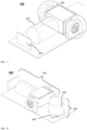
- FIG. 2 shows actuator 100 as part of folded camera structure (FCS) or simply "folded camera” 200.
- actuator 100 is used to rotate OPFE (e.g. prism) 102.
- the operation (actuation) of actuator 100 in folded camera 200 creates an extended tele field of view (FOV T ), of the type described for example in US provisional patent applications 62/272367 and 62/361150 .
- a typical rotational actuation stroke of actuator 100 in this case may be in the range of ⁇ 5 to ⁇ 20 degrees of the original position of OPFE 102, with resolution of at least 8 and up to 100 distinguishable steps (possible OPFE positions).
- Camera 200 further includes a lens element 202, and an image sensor 204.
- Camera 200 may further include an actuation mechanism for focusing and ⁇ or auto-focus (AF) of lens element 202. This actuation mechanism is not shown in FIG. 2 , but may be for example as described in US patent 9392188 .
- FIG. 3 shows folded camera 200 a part of a dual-camera (or "dual-aperture camera") 300.
- Dual-camera 300 also includes a standard “upright” camera 302.
- Camera 302 has a standard camera structure, known in the art, and includes a lens 304 and an image sensor 306.
- Camera 302 may also include other parts such as actuation mechanism for the lens, a mechanical shield, a chassis and other parts, all known in the art and not shown in FIG. 3 .
- Dual-aperture cameras such as camera 300 and their operation and use are described in detail in, for example, international patent application PCT/IB2016/056060 .
- Magnetic sensing element 126 is for example (as mentioned above) a Hall bar element, capable of measuring magnetic field in the X direction indicated in FIG. 1 .
- magnet 110 is rigidly coupled to (or is part of) actuated sub-assembly 116, while sensing element 126 is rigidly coupled to (or is part of) stationary sub-assembly 122.
- Magnet 110 has for example a magnetic field direction along the Z axis, such that the North magnetic pole is on the positive Z direction and the South magnetic pole is in the negative Z direction.
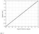
- FIG. 4 shows a simulation of the effect of the magnetic field in the X direction on sensing element 126 as function of actuated sub-assembly 116 (and magnet 110 ) rotating around axis 104. It is apparent that the magnetic field changes monotonically from a negative value of about -0.2T at one end of the movement range to +0.2T at the other end of the movement (rotation) range.
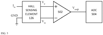
- FIG. 5 shows a known art electrical circuit 500 which allows reading of the magnetic field by a Hall bar element 126.
- Hall bar element 126 has 4 connectors marked as Iin, Gnd, V+ and V-.
- a current typically in the range of 1-20mA is driven in Iin and flows through Hall bar element 126 to the ground (GND).
- Hall bar element 126 has a typical resistance in the range of 200-3000 k ⁇ .
- Vout Vp - Vm
- Vp (Vin + Vout)/2
- Vm (Vin - Vout)/2
- ⁇ 0.5mV/mT, such that for the graph seen in FIG. 4B, Vout is in the range of -100mV to 100mV in the movement range.
- Amplifier 502 is an operational amplifier (op-amp) with a 3V driving voltage.
- the inputs of op-amp 502 are Vp and Vm.
- the output of op-amp 502 is Vp + ⁇ (Vp - Vm).
- Vamp the voltage output of op-amp 502 (Vamp) in this example is in the range of 0-3V.
- Vamp is sampled by an analog-to-digital converter (ADC) 504, with resolution in the range of 8-14bits, in this example 12 bits.
- ADC analog-to-digital converter
- circuit 500 allows the measurement of the motion range of actuator 100 with 12bit maximal resolution (or 8-16 bits in other cases). For a 20 degree scanning range, this allows approximately 0.005 degree resolution. This resolution is worse than required.
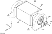
- FIG. 6A illustrates in an isomeric view
- FIG. 6B illustrates in an exploded view an actuator 600 of a rotational VCM according to another exemplary embodiment disclosed herein.
- Actuator 600 allows an extended OPFE scanning range plus OIS abilities. Compared to actuator 100, actuator 600 has an accurate position sensing mechanism that allows accuracy of 1/200 degrees, as described below. Thus, the control circuitry of actuator 600 can remain operative while the OPFE is rotated to a desired potion without reducing image optical quality.
- Actuator 600 is similar mechanically to actuator 100 and includes all elements as actuator 100 (which consequently are numbered with identical numbers). The difference between actuator 600 and actuator 100 is that actuator 600 further includes two ball bearings 602a and 602b , typically made of stainless steel. Ball bearings 602a and 602b are fixedly attached (e.g. glued) inside housings 120a and 120b respectively. Actuated sub-assembly 116 is positioned inside stationary sub-assembly 122 such that hinges 114a and 114b are positioned inside ball bearings 602a and 602b respectively. Hinges 114a and 114b and bearings 602a and 602b are all concentric and lie on axis 104.
- a typical low friction coefficient of ball bearing 602a and 602b may be in the range of 0.001-0.005.
- FIG. 7 shows actuator 600 as part of a folded camera 700.
- actuator 600 is used to rotate a light folding element as described above with reference to camera 200.
- the actuation creates an extended zoom field of view (FOV) as mentioned above and in addition provides OIS as described for example in PCT/IB2016/052179.
- FOV extended zoom field of view
- the typical rotational actuation stroke of actuator 600 should be in the range of ⁇ 8 to ⁇ 18 degrees of the original position of the light folding element, with resolution of at least 0.002 degrees.
- Camera 700 may further include elements described with reference to camera 200 above.
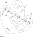
- FIG. 8 shows camera 700 a part of a dual-camera 800.
- the description and use of dual-camera 800 are similar to those in camera 300 and are therefore not repeated.
- FIG. 9 shows an electrical circuit 900 which allows reading of the magnetic field by Hall bar sensing element 126 for the extended scanning, according to an exemplary embodiment disclosed herein.
- Circuit 900 extends circuit 500 by including, in addition to the elements of circuit 500, a digital-to-analog converter (DAC) 902 with resolution in the range of 8-14bits, and in this example 12 bits. Namely, the range 0 to 3V is divided to 4096 levels, or less than 1mV.
- DAC 902 provides a reference voltage for a second amplification step, as explained next.
- the analog output of DAC 902 is marked as Vdac.
- Circuit 900 further includes op-amp 904, operating under voltage of 3V and amplification ⁇ in the range of 100-4000.
- the inputs of op-amp 904 are Vamp and Vdac.
- the output of op-amp 904 is Vdac + ⁇ (Vdac - Vamp).
- Vdac is set in the following manner: the tilt (rotation) target of actuator 600 is known (decided by the user).
Abstract
Description
- Embodiments disclosed herein relate in general to digital cameras and in particular to thin multi-aperture zoom digital cameras.
- Personal electronic devices such as smartphones having two back cameras (also referred to as "dual-cameras" or "dual-aperture cameras") are known and available commercially. The two back cameras have respective lenses with different fixed focal lengths and respective image sensors (or simply "sensors") operated to capture image data (or "image"). Even though each lens/sensor combination is aligned to look in the same direction, each will capture an image of the same scene with a different field of view (FOV).
- A Tele camera with adjustable FOVT for maximizing zooming capabilities is disclosed for example in commonly owned and invented PCT patent application
PCT/IB2016/057366 titled "Dual-aperture zoom digital camera with automatic adjustable tele field of view". The adjustable FOV involves scanning enabled by a step motor. Recently, step motors have been replaced by voice coil motor (VCM) technology. VCM actuation is used for autofocus (AF) and\or optical image stabilization (OIS). However, known VCM actuator technology, in particular as used in folded cameras, may have a limited scanning range and a given VCM actuator may perform only OIS, which requires motion compensation in a very limited range. - Systems that rotate an OPFE for OIS are described for example in co-assigned international patent application
PCT/IB2016/052179 , titled "Auto focus and optical image stabilization in a compact folded camera". - Therefore, there is a need for, and it would be advantageous to have a VCM actuation mechanism for adjustable FOVT with extended scanning range. In addition, it would be advantageous to have a VCM actuation mechanism for adjustable FOVT with extended scanning range that can simultaneously support scanning in an extended range and OIS.
- Embodiments disclosed herein relate to VCM actuators for Tele folded cameras with adjustable FOVT, such as the camera described in PCT/IB2016/057366. The disclosed actuators are designed to maximize zooming and scanning capabilities. Some exemplary disclosed embodiments also allow OIS in parallel with image scanning.
- In an exemplary embodiment, there is provided an actuator for rotating an OPFE over a scanning range in which OPFE position is controlled by a non-accurate position sensing mechanism that determines an allowable jitter limit, the actuator comprising: an actuated sub-assembly rigidly coupled to the OPFE and having two hinges that define a rotation axis, and a stationary sub-assembly having two housings, wherein each housing is nested in a respective hinge of the stationary sub-assembly to form a housing-hinge pair, wherein a center-of-mass of the actuated sub-assembly is positioned to coincide with the rotation axis to limit jitter arising from the OPFE being rotated to and stopped at a given OPFE position to be no larger than an allowable limit.
- In an embodiment, each housing-hinge pair has a degree of friction designed to assist in limiting the jitter arising from the OPFE being rotated to and stopped at a given OPFE position to be no larger than the allowable limit.
- In an embodiment, the stationary sub-assembly includes a position sensor for sensing the given OPFE position.
- In an embodiment, the position sensor includes a Hall bar sensing element.
- In an embodiment, the scanning range is larger than ±1.5 degrees around a rest position of the OPFE.
- In an embodiment, the scanning range is at least ±5 degrees around the rest position of the OPFE.
- In an embodiment, the scanning range is up to ±20 degrees around the rest position of the OPFE.
- Non-limiting examples of embodiments disclosed herein are described below with reference to figures attached hereto that are listed following this paragraph. Identical structures, elements or parts that appear in more than one figure are generally labeled with a same numeral in all the figures in which they appear. The drawings and descriptions are meant to illuminate and clarify embodiments disclosed herein, and should not be considered limiting in any way.
-
FIG. 1A shows an actuator capable of extended scan in an isomeric view according to an exemplary embodiment; -
FIG. 1B shows the actuator ofFIG. 1A in a backside view; -
FIG. 1C shows the actuator ofFIG. 1A in an exploded view; -
FIG. 2 shows the actuator ofFIGS. 1A-C in a folded camera with lens and sensor; -
FIG. 3 shows the folded camera and actuator ofFIG. 2 in a dual-camera; -
FIG. 4 shows a simulation of the effect of a magnetic field in the X direction on a sensing element as function of actuatedsub-assembly 116 and magnet 110) rotating aroundaxis 104; -
FIG. 5 shows schematically a sensing circuit for the actuator ofFIGS. 1A-C ; -
FIG. 6A shows an actuator capable of extended scan + OIS in an isomeric view according to another exemplary embodiment; -
FIG. 6B shows the actuator ofFIG.6 in an exploded view; -
FIG. 7 shows the actuator ofFIGS. 6A -C in a folded camera with lens and sensor; -
FIG. 8 shows the folded camera and actuator ofFIG. 7 in a dual-camera; -
FIG. 9 shows schematically a sensing circuit for the actuator ofFIGS. 6A -C. -
FIGS. 1A -D illustrate in various views anactuator 100 of a rotational voice coil motor (VCM), according to an example of the presently disclosed subject matter. Actuator 100 enables an extended OPFE scanning range relative to the needs of other systems that rotate an OPFE for OIS (where the rotation is typically of ±1 degree, as e.g. the system described in co-assigned PCT patent applicationPCT/IB2016/052179 ) and enables as well adjustment of FOVT.FIG. 1A showsactuator 100 in an isometric view,FIG. 1B showsactuator 100 from a back view, andFIG. 1C showsactuator 100 in an exploded view.Actuator 100 enables rotation (in an angle referred to as "ϕ") of an OPFE 102 (for example a prism or mirror) around a single axis 104 (i.e. around for example the X axis in the coordinate system shown and used in all figures), as described below.Axis 104 may also be referred to as "rotation axis". In various embodiments, the extended range of ϕ may be for example in the range of 10 degrees to 40 degrees (or ±5 degrees to ±20 degrees around an initial "rest" position). In an exemplary embodiment, ϕ = 20 degrees or ±10 degrees around the rest position In comparison, known designs in which the OPFE is rotated (tilted) for OIS purposes only enable a limited rotation range of 0.5 to 3 degrees or ±0.25 to ±1.5 degrees around the rest position. - In
actuator 100, OPFE 102 is held in an optical element holder (or simply "holder") 106, which may be made, for example by plastic molding, fit to the shape of OPFE 102. Anactuation magnet 108 is fixedly attached (e.g. glued) tooptical element holder 106 from below (negative Z direction inFIG. 1B ). Asensing magnet 110 is fixedly attached (e.g. glued) toholder 106 on one side of the holder in agroove 112. Two hinges 114a and 114b are fixedly attached (e.g. glued) toholder 106 on two sides.Hinges OPFE 102,optical element holder 106,actuation magnet 108,sensing magnet 110, and hinges 114a and 114b will be referred to henceforth as "actuated sub-assembly" 116. -
Actuator 100 further includes abase 118, made for example of plastic, and twohousings housings base 118. Is some embodiments,base 118 and either one or both ofhousings housing 120a and\orhousing 120b may include several parts which are assembled and e.g. glued only during the actuator assembly process.Base 118 andhousings Stationary sub-assembly 122 further includes a Hallbar sensing element 126 and acoil 124, both described below. - Actuated
sub-assembly 116 is positioned insidestationary sub-assembly 122 such that hinges 114a and 114b are positioned insidehousings Hinges sub-assembly 116 and ofOPFE 102 aroundaxis 104. The plastic moldings ofbase 118 and/oroptical element holder 106 may be used as a mechanical stopper for actuated sub-assembly 116 to prevent motion beyond ϕ degrees. - In some embodiments,
axis 104 is positioned through the center-of-mass of actuatedsub-assembly 116. The "mass" includes elements 102,106, 108, 110, 114a and 114b. In such embodiments, an external rotation of actuator 100 (caused e.g. by a user rotating a device including the actuator) will not cause a relative rotation between actuated sub-assembly 116 andstationary sub-assembly 122. -
Actuator 100 further includes awound coil 124, for example of a stadium shape, typically with a few tens of windings (e.g. in a not limiting range of 50-250) and with a typical resistance of 10-30 ohm.Coil 124 is located belowmagnet 108 such that nominally their centers overlap when the actuated sub-assembly is at rest.Magnet 108 can be for example a permanent magnet, made from a neodymium alloy (e.g. Nd2Fe14B) or a samarium-cobalt alloy (e.g. SmCo5).Magnet 108 can be fabricated (e.g. sintered) such that it changes the magnetic poles direction: on the positive Y side, the North magnetic pole faces the negative Z direction, while on the negative Y side, the North magnetic pole faces the positive Z direction.Coil 124 is connected to external current driving circuit (not shown), the driving circuit capable of sending input currents tocoil 124. Current incoil 124 creates a Lorentz force due to the magnetic field of magnet 108: for example, a current in a clockwise direction will create a force in the positive Y direction, while a current in counterclockwise direction will create a force in the negative Y direction. The full magnetic scheme (i.e. the full magnetic simulation of the magnetic field caused by magnet 108) is known in the art, and described, for example, in detail in patent applicationPCT/IB2016/052179 . - When the magnetic force applied by
coil 124 is in the positive and negative Y directions, the hinge mechanical structure confines actuated sub-assembly 116 to rotate aroundaxis 104. AHall bar element 126 can sense the intensity and direction of the magnetic field ofsensing magnet 110.Sensing magnet 110 can be for example a permanent magnet, made from a neodymium alloy (e.g. Nd2Fe14B) or a samarium-cobalt alloy (e.g. SmCo5).Magnet 110 can be fabricated (e.g. sintered), such that its North pole is to the Z direction whenactuator 100 is at rest. Upon actuation, the relative position of actuatedsub-assembly 116 andHall bar element 126 is changed. The intensity and direction of the magnetic field senses byHall bar element 126 changes as well, and thus the position of actuatedsub-assembly 116 can be determined. A closed loop control circuit (not shown) is used to control the position of the actuated sub-assembly and set to the position required by optical demands. The closed loop control circuit has a single input - the signal ofHall bar element 126, and a single output - the amount of current applied incoil 124. The closed loop control circuit may be implemented in an integrated circuit (IC) (not shown). Operation of a closed loop control system with single input and single output (SISO) system is known in the art. Such a closed loop control circuit may, for example, be a linear "proportional-integral-differential" (PID) control. In some embodiments, the single IC may be implemented in a controller insideHall bar element 126. In other embodiments, the IC may be a separate chip, which can be located externally to the camera. - The step resolution and jitter (noise) of
actuator 100, as described below, may be limited by a "non-accurate" sensing mechanism circuitry to 1/1000 of ϕ. For usage requirements, a 1/80 of ϕ step resolution may be acceptable, as described in PCT patent applicationPCT/IB2016/057366 . However, afteractuator 100 has positioned the OPFE in a specific position, considerations of prevention of image blur require a jitter of no more than 1/200 degree. Insystem 100 and for example, 1/200 degree is equal to 1/4000 of ϕ, which is smaller than the 1/1000 ϕ jitter limit allowed by the sensing circuitry. To address this problem, a friction-based mechanism is provided to limit jitter to a level that does not exceed the allowable limit (1/200 degree, which in the example is 1/4000 of ϕ). For example, in some cases, significant friction may be designed and introduced betweenhinges housings axis 104 through the center-of-mass of actuatedsub-assembly 116 will ensure that external torques and forces (caused for example by user hand shake) will maintain actuated sub-assembly 116 fixed relative tostationary sub-assembly 122. The power turn-off also helps reduce the system power consumption. - For example, assume actuated sub-assembly with a mass of 500mg and a moment of inertia around
axis 104 of 1000 mg-mm2. Assume a friction coefficient of 0.7 between stainless steel hinges 114a-b andplastic housings 120a-b.Axis 104 with a diameter of 0.7mm is nominally designed to pass through the center-of-mass of actuatedsub-assembly 106. However due to mechanical tolerances during assembly,axis 104 may shift by up to 20 micrometers (µm), which will cause a gravity torque of up to 0.0001N-mm. Typical handshakes are up to 2Hz and 0.1 degrees, causing angular accelerations of up to 0.3 rad/sec2, and moment of inertia-provided torques are typically limited to 0.0003 N-mm. Thus, both gravity and handshake torques will not overcome a friction torque (mass x friction coefficient x hinge radius) of 0.001225 N-mm after current turn off. -
FIG. 2 shows actuator 100 as part of folded camera structure (FCS) or simply "folded camera" 200. In foldedcamera 200,actuator 100 is used to rotate OPFE (e.g. prism) 102. The operation (actuation) ofactuator 100 in foldedcamera 200 creates an extended tele field of view (FOVT), of the type described for example inUS provisional patent applications 62/272367 62/361150 actuator 100 in this case may be in the range of ±5 to ±20 degrees of the original position ofOPFE 102, with resolution of at least 8 and up to 100 distinguishable steps (possible OPFE positions).Camera 200 further includes alens element 202, and animage sensor 204.Camera 200 may further include an actuation mechanism for focusing and\or auto-focus (AF) oflens element 202. This actuation mechanism is not shown inFIG. 2 , but may be for example as described inUS patent 9392188 -
FIG. 3 shows folded camera 200 a part of a dual-camera (or "dual-aperture camera") 300. Dual-camera 300 also includes a standard "upright"camera 302.Camera 302 has a standard camera structure, known in the art, and includes alens 304 and animage sensor 306.Camera 302 may also include other parts such as actuation mechanism for the lens, a mechanical shield, a chassis and other parts, all known in the art and not shown inFIG. 3 . Dual-aperture cameras such ascamera 300 and their operation and use are described in detail in, for example, international patent applicationPCT/IB2016/056060 . -
Magnetic sensing element 126 is for example (as mentioned above) a Hall bar element, capable of measuring magnetic field in the X direction indicated inFIG. 1 . Inactuator 100,magnet 110 is rigidly coupled to (or is part of) actuated sub-assembly 116, while sensingelement 126 is rigidly coupled to (or is part of)stationary sub-assembly 122.Magnet 110 has for example a magnetic field direction along the Z axis, such that the North magnetic pole is on the positive Z direction and the South magnetic pole is in the negative Z direction. -
FIG. 4 shows a simulation of the effect of the magnetic field in the X direction onsensing element 126 as function of actuated sub-assembly 116 (and magnet 110) rotating aroundaxis 104. It is apparent that the magnetic field changes monotonically from a negative value of about -0.2T at one end of the movement range to +0.2T at the other end of the movement (rotation) range. -
FIG. 5 shows a known art electrical circuit 500 which allows reading of the magnetic field by aHall bar element 126.Hall bar element 126 has 4 connectors marked as Iin, Gnd, V+ and V-. A current typically in the range of 1-20mA is driven in Iin and flows throughHall bar element 126 to the ground (GND).Hall bar element 126 has a typical resistance in the range of 200-3000 kΩ. In this example, consider a sensing element with resistance 1200ohm and current Iin = 2.5mA, such that the voltage drop between Iin and Gnd is 3V and is marked as Vin = 3V. For the case of 0 (zero) magnetic field B in the X direction Vp = Vm = Vin/2 = 1. 5V. If a magnetic field exists inHall bar element 126, a voltage drop will be created between Vp and Vm, marked as Vout = Vp - Vm, such that Vp = (Vin + Vout)/2 and Vm = (Vin - Vout)/2. The size of Vout is proportional to the magnetic field B on the sensing element, i.e. Vout = αB. For a constant current Iin=2.5mA, α has a typical value in the range of 0.2- 2mV/mT. In this example, consider α=0.5mV/mT, such that for the graph seen in FIG. 4B, Vout is in the range of -100mV to 100mV in the movement range. -
Amplifier 502 is an operational amplifier (op-amp) with a 3V driving voltage. The details of operation of op-amp 502 are known in the art and described here briefly. Op-amp 502 has an amplification factor β in the range of 5-200. In this example, assume an amplification factor of β=15. The inputs of op-amp 502 are Vp and Vm. The output of op-amp 502 is Vp + β(Vp - Vm). Hence, the voltage output of op-amp 502 (Vamp) in this example is in the range of 0-3V. Vamp is sampled by an analog-to-digital converter (ADC) 504, with resolution in the range of 8-14bits, in this example 12 bits. Namely, therange 0 to 3V is divided to 4096 levels. Thus, circuit 500 allows the measurement of the motion range ofactuator 100 with 12bit maximal resolution (or 8-16 bits in other cases). For a 20 degree scanning range, this allows approximately 0.005 degree resolution. This resolution is worse than required. -
FIG. 6A illustrates in an isomeric view, andFIG. 6B illustrates in an exploded view anactuator 600 of a rotational VCM according to another exemplary embodiment disclosed herein.Actuator 600 allows an extended OPFE scanning range plus OIS abilities. Compared toactuator 100,actuator 600 has an accurate position sensing mechanism that allows accuracy of 1/200 degrees, as described below. Thus, the control circuitry ofactuator 600 can remain operative while the OPFE is rotated to a desired potion without reducing image optical quality. -
Actuator 600 is similar mechanically toactuator 100 and includes all elements as actuator 100 (which consequently are numbered with identical numbers). The difference betweenactuator 600 andactuator 100 is thatactuator 600 further includes twoball bearings Ball bearings housings sub-assembly 116 is positioned insidestationary sub-assembly 122 such that hinges 114a and 114b are positioned insideball bearings Hinges bearings axis 104. The mechanical structure described allows the rotation of actuatedsub-assembly 116 and light-folding-element 102 around the X axis with very low friction. A typical low friction coefficient ofball bearing -
FIG. 7 shows actuator 600 as part of a foldedcamera 700. In foldedcamera 700,actuator 600 is used to rotate a light folding element as described above with reference tocamera 200. The actuation creates an extended zoom field of view (FOV) as mentioned above and in addition provides OIS as described for example in PCT/IB2016/052179. As also indicated above, the typical rotational actuation stroke ofactuator 600 should be in the range of ±8 to ±18 degrees of the original position of the light folding element, with resolution of at least 0.002 degrees.Camera 700 may further include elements described with reference tocamera 200 above. -
FIG. 8 shows camera 700 a part of a dual-camera 800. The description and use of dual-camera 800 are similar to those incamera 300 and are therefore not repeated. - In
actuator 600, the actuation mechanism is responsible for both an extended scanning range and OIS. Thus, a higher scanning resolution is required, relative to that inactuator 100.FIG. 9 shows an electrical circuit 900 which allows reading of the magnetic field by Hallbar sensing element 126 for the extended scanning, according to an exemplary embodiment disclosed herein. Circuit 900 extends circuit 500 by including, in addition to the elements of circuit 500, a digital-to-analog converter (DAC) 902 with resolution in the range of 8-14bits, and in this example 12 bits. Namely, therange 0 to 3V is divided to 4096 levels, or less than 1mV.DAC 902 provides a reference voltage for a second amplification step, as explained next. The analog output ofDAC 902 is marked as Vdac. Circuit 900 further includes op-amp 904, operating under voltage of 3V and amplification γ in the range of 100-4000. Exemplary, op-amp 904 demonstrates amplification of γ = 500. The inputs of op-amp 904 are Vamp and Vdac. The output of op-amp 904 is Vdac + γ (Vdac - Vamp). Vdac is set in the following manner: the tilt (rotation) target ofactuator 600 is known (decided by the user). The target range ϕ is divided into S steps, S is an integer, S > γ, in this example S = 3000 (0.2 degrees in this example). For a given tilt target, a value "s" marks the closest integer step in the range. For example, if the target is -5 degrees than s = 750. The DAC output is set to Vin/2 - Vrange/2 + Vrange∗s/S. This setting of DAC output can assure that when the position of the actuator is closer to the target than ϕ/S the output of op-amp 502, Vamp2 is in the range of 0-3V. Vamp2 is sampled by anADC 906, with resolution in the range of 8-14bits, and in this example 12 bits. Namely, therange 0 to 3V is divided to 4096 levels. Thus, circuit 900 allows the measurement of the motion range ofactuator 100 with γ times precision more than circuit 500. For 20 degrees scanning range, with γ = 500, this allows approximately 0.00001 degree (10 micro-degree) resolution. - All publications, patents and patent applications mentioned in this specification are herein incorporated in their entirety by reference into the specification, to the same extent as if each individual publication, patent or patent application was specifically and individually indicated to be incorporated herein by reference. In addition, citation or identification of any reference in this application shall not be construed as an admission that such reference is available as prior art to the present disclosure.
- While this disclosure has been described in terms of certain embodiments and generally associated methods, alterations and permutations of the embodiments and methods will be apparent to those skilled in the art. The disclosure is to be understood as not limited by the specific embodiments described herein, but only by the scope of the appended claims.
Claims (15)
- A folded digital camera comprising:a) an optical path folding element (OPFE) for folding an optical path from an imaged object or scene toward a lens and an image sensor of the folded digital camera, the folded digital camera having a field of view (FOV); andb) a single actuator including a single coil and single magnet for rotating the OPFE for optical image stabilization (OIS), wherein the rotation of the OPFE further enables adjustment of the FOV over an extended scanning range greater than ±8 degrees and wherein OIS is enabled over the extended scanning range with sufficient resolution.
- The folded digital camera of claim 1, wherein the sufficient resolution is at least 0.002 degrees.
- The folded digital camera of claim 1, wherein the sufficient resolution is at least 0.005 degrees.
- The folded digital camera of any of the claims 1-3, wherein the extended scanning range is up to ±20 degrees around a rest position of the OPFE.
- The folded digital camera of any of the claims 1-4, wherein the single actuator includes a position sensor for sensing an OPFE position relative to a stationary base of the folded digital camera.
- The folded digital camera of claim 5, wherein the position sensor includes a Hall bar sensor.
- The folded digital camera of any of the claims 1-4, wherein the single coil and single magnet form a rotational voice coil motor (VCM) for rotating the OPFE.
- The folded digital camera of claim 7, wherein the single magnet is mechanically coupled to the OPFE and wherein the single coil is coupled to the stationary base.
- A method, comprising:a) providing a folded digital camera having an optical path folding element (OPFE) for folding an optical path from an imaged object or scene toward a lens and an image sensor of the folded digital camera, the folded digital camera having a field of view (FOV); andb) rotating the OPFE with a single actuator including a single coil and single magnet to enable optical image stabilization (OIS), wherein the rotation of the OPFE further enables adjustment of the FOV over an extended scanning range greater than ±8 degrees and wherein OIS is enabled over the extended scanning range with sufficient resolution.
- The method of claim 9, wherein the sufficient resolution is at least 0.002 degrees.
- The method of claim 9, wherein the sufficient resolution is at least 0.005 degrees.
- The method of any of the claims 9-11, wherein the extended scanning range is up to ±20 degrees around a rest position of the OPFE.
- The method of any of the claims 9-12, wherein the single actuator includes a position sensor for sensing an OPFE position relative to a stationary base of the folded digital camera.
- The method of any of the claims 9-12, wherein the single coil and single magnet form a rotational voice coil motor (VCM) for rotating the OPFE.
- The method of claim 14, wherein the single magnet is mechanically coupled to the OPFE and wherein the single coil is coupled to the stationary base.
Applications Claiming Priority (4)
| Application Number | Priority Date | Filing Date | Title |
|---|---|---|---|
| US201662439518P | 2016-12-28 | 2016-12-28 | |
| EP17887407.9A EP3563193B1 (en) | 2016-12-28 | 2017-12-06 | Folded camera structure with an extended light-folding-element scanning range |
| PCT/IB2017/057706 WO2018122650A1 (en) | 2016-12-28 | 2017-12-06 | Folded camera structure with an extended light-folding-element scanning range |
| EP21157082.5A EP3842853B1 (en) | 2016-12-28 | 2017-12-06 | Folded camera structure with an extended light-folding-element scanning range |
Related Parent Applications (3)
| Application Number | Title | Priority Date | Filing Date |
|---|---|---|---|
| EP21157082.5A Division EP3842853B1 (en) | 2016-12-28 | 2017-12-06 | Folded camera structure with an extended light-folding-element scanning range |
| EP21157082.5A Division-Into EP3842853B1 (en) | 2016-12-28 | 2017-12-06 | Folded camera structure with an extended light-folding-element scanning range |
| EP17887407.9A Division EP3563193B1 (en) | 2016-12-28 | 2017-12-06 | Folded camera structure with an extended light-folding-element scanning range |
Publications (2)
| Publication Number | Publication Date |
|---|---|
| EP4246993A2 true EP4246993A2 (en) | 2023-09-20 |
| EP4246993A3 EP4246993A3 (en) | 2024-03-06 |
Family
ID=62710940
Family Applications (3)
| Application Number | Title | Priority Date | Filing Date |
|---|---|---|---|
| EP17887407.9A Active EP3563193B1 (en) | 2016-12-28 | 2017-12-06 | Folded camera structure with an extended light-folding-element scanning range |
| EP23190556.3A Pending EP4246993A3 (en) | 2016-12-28 | 2017-12-06 | Folded camera structure with an extended light-folding-element scanning range |
| EP21157082.5A Active EP3842853B1 (en) | 2016-12-28 | 2017-12-06 | Folded camera structure with an extended light-folding-element scanning range |
Family Applications Before (1)
| Application Number | Title | Priority Date | Filing Date |
|---|---|---|---|
| EP17887407.9A Active EP3563193B1 (en) | 2016-12-28 | 2017-12-06 | Folded camera structure with an extended light-folding-element scanning range |
Family Applications After (1)
| Application Number | Title | Priority Date | Filing Date |
|---|---|---|---|
| EP21157082.5A Active EP3842853B1 (en) | 2016-12-28 | 2017-12-06 | Folded camera structure with an extended light-folding-element scanning range |
Country Status (5)
| Country | Link |
|---|---|
| US (2) | US11531209B2 (en) |
| EP (3) | EP3563193B1 (en) |
| KR (1) | KR102269547B1 (en) |
| CN (2) | CN114051092A (en) |
| WO (1) | WO2018122650A1 (en) |
Families Citing this family (6)
| Publication number | Priority date | Publication date | Assignee | Title |
|---|---|---|---|---|
| WO2020243856A1 (en) * | 2019-06-01 | 2020-12-10 | 瑞声光学解决方案私人有限公司 | Prism module and periscope camera |
| EP4045959A4 (en) * | 2019-12-03 | 2022-12-21 | Corephotonics Ltd. | Actuators for providing an extended two-degree of freedom rotation range |
| CN115702375A (en) | 2020-06-12 | 2023-02-14 | 华为技术有限公司 | Compact actuator assembly for optical path folding element |
| EP4065934A4 (en) * | 2020-07-31 | 2023-07-26 | Corephotonics Ltd. | Hall sensor-magnet geometry for large stroke linear position sensing |
| JP2022055837A (en) | 2020-09-29 | 2022-04-08 | 日本電産サンキョー株式会社 | Optical unit |
| KR20220079179A (en) * | 2020-12-04 | 2022-06-13 | 삼성전자주식회사 | Method for compensating camera shake and electronic device thereof |
Citations (4)
| Publication number | Priority date | Publication date | Assignee | Title |
|---|---|---|---|---|
| WO2016052179A1 (en) | 2014-09-30 | 2016-04-07 | 富士フイルム株式会社 | Cell imaging device and cell imaging method |
| WO2016056060A1 (en) | 2014-10-07 | 2016-04-14 | 株式会社日立製作所 | Computer and vector setting method |
| WO2016057366A1 (en) | 2014-10-08 | 2016-04-14 | Dieterch Standard, Inc. | Integrated orifice plate assembly |
| US9392188B2 (en) | 2014-08-10 | 2016-07-12 | Corephotonics Ltd. | Zoom dual-aperture camera with folded lens |
Family Cites Families (292)
| Publication number | Priority date | Publication date | Assignee | Title |
|---|---|---|---|---|
| US4199785A (en) | 1979-01-05 | 1980-04-22 | Honeywell Inc. | Electronic zoom system |
| US5099263A (en) | 1984-11-10 | 1992-03-24 | Minolta Camera Kabushiki Kaisha | Variable focal length camera |
| DE58902538D1 (en) | 1988-05-19 | 1992-12-03 | Siemens Ag | METHOD FOR OBSERVING A SCENE AND DEVICE FOR IMPLEMENTING THE METHOD. |
| DE3927334C1 (en) | 1989-08-18 | 1991-01-10 | Messerschmitt-Boelkow-Blohm Gmbh, 8012 Ottobrunn, De | |
| US5032917A (en) | 1990-03-12 | 1991-07-16 | Rca Licensing Corporation | Video signal blending apparatus |
| JPH0443773A (en) | 1990-06-11 | 1992-02-13 | Matsushita Electric Ind Co Ltd | Arithmetic circuit |
| US5041852A (en) | 1990-10-18 | 1991-08-20 | Fjui Photo Film Co., Ltd. | Camera shake correction system |
| JP3261152B2 (en) | 1991-03-13 | 2002-02-25 | シャープ株式会社 | Imaging device having a plurality of optical systems |
| US5657402A (en) | 1991-11-01 | 1997-08-12 | Massachusetts Institute Of Technology | Method of creating a high resolution still image using a plurality of images and apparatus for practice of the method |
| US5248971A (en) | 1992-05-19 | 1993-09-28 | Mandl William J | Method and apparatus for multiplexed oversampled analog to digital modulation |
| JPH06177706A (en) | 1992-12-08 | 1994-06-24 | Sony Corp | Signal processing unit |
| EP0605045B1 (en) | 1992-12-29 | 1999-03-31 | Laboratoires D'electronique Philips S.A.S. | Image processing method and apparatus for generating one image from adjacent images |
| US5682198A (en) | 1993-06-28 | 1997-10-28 | Canon Kabushiki Kaisha | Double eye image pickup apparatus |
| US6128416A (en) | 1993-09-10 | 2000-10-03 | Olympus Optical Co., Ltd. | Image composing technique for optimally composing a single image from a plurality of digital images |
| US6714665B1 (en) | 1994-09-02 | 2004-03-30 | Sarnoff Corporation | Fully automated iris recognition system utilizing wide and narrow fields of view |
| CA2155719C (en) | 1994-11-22 | 2005-11-01 | Terry Laurence Glatt | Video surveillance system with pilot and slave cameras |
| US5768443A (en) | 1995-12-19 | 1998-06-16 | Cognex Corporation | Method for coordinating multiple fields of view in multi-camera |
| JP3728607B2 (en) * | 1996-02-23 | 2005-12-21 | 株式会社ニコン | Optical device with shake correction mechanism |
| US5717512A (en) * | 1996-05-15 | 1998-02-10 | Chmielewski, Jr.; Thomas A. | Compact image steering and focusing device |
| US5982951A (en) | 1996-05-28 | 1999-11-09 | Canon Kabushiki Kaisha | Apparatus and method for combining a plurality of images |
| US5926190A (en) | 1996-08-21 | 1999-07-20 | Apple Computer, Inc. | Method and system for simulating motion in a computer graphics application using image registration and view interpolation |
| JPH10126796A (en) | 1996-09-12 | 1998-05-15 | Eastman Kodak Co | Digital camera for dynamic and still images using dual mode software processing |
| US5805325A (en) * | 1996-10-25 | 1998-09-08 | Lockheed Martin Missiles & Space Co. | Inertially stabilized mirror system |
| US5960218A (en) | 1997-02-18 | 1999-09-28 | Mobi Corporation | Dual focal length camera |
| US5940641A (en) | 1997-07-10 | 1999-08-17 | Eastman Kodak Company | Extending panoramic images |
| US6148120A (en) | 1997-10-30 | 2000-11-14 | Cognex Corporation | Warping of focal images to correct correspondence error |
| US6268611B1 (en) | 1997-12-18 | 2001-07-31 | Cellavision Ab | Feature-free registration of dissimilar images using a robust similarity metric |
| JP3695119B2 (en) | 1998-03-05 | 2005-09-14 | 株式会社日立製作所 | Image synthesizing apparatus and recording medium storing program for realizing image synthesizing method |
| JP2000010139A (en) * | 1998-06-18 | 2000-01-14 | Asahi Optical Co Ltd | Image shake correcting camera and image shake correcting method for camera |
| US6208765B1 (en) | 1998-06-19 | 2001-03-27 | Sarnoff Corporation | Method and apparatus for improving image resolution |
| US6611289B1 (en) | 1999-01-15 | 2003-08-26 | Yanbin Yu | Digital cameras using multiple sensors with multiple lenses |
| US6738073B2 (en) | 1999-05-12 | 2004-05-18 | Imove, Inc. | Camera system with both a wide angle view and a high resolution view |
| US20020075258A1 (en) | 1999-05-12 | 2002-06-20 | Imove Inc. | Camera system with high resolution image inside a wide angle view |
| US20020063711A1 (en) | 1999-05-12 | 2002-05-30 | Imove Inc. | Camera system with high resolution image inside a wide angle view |
| US6346950B1 (en) | 1999-05-20 | 2002-02-12 | Compaq Computer Corporation | System and method for display images using anamorphic video |
| US7038716B2 (en) | 1999-07-30 | 2006-05-02 | Pixim, Inc. | Mobile device equipped with digital image sensor |
| US7015954B1 (en) | 1999-08-09 | 2006-03-21 | Fuji Xerox Co., Ltd. | Automatic video system using multiple cameras |
| US6650368B1 (en) | 1999-10-26 | 2003-11-18 | Hewlett-Packard Development Company, Lp. | Digital camera and method of enhancing zoom effects |
| US6643416B1 (en) | 1999-11-30 | 2003-11-04 | Eastman Kodak Company | Method for determining necessary resolution for zoom and crop images |
| US20020005902A1 (en) | 2000-06-02 | 2002-01-17 | Yuen Henry C. | Automatic video recording system using wide-and narrow-field cameras |
| JP4501239B2 (en) | 2000-07-13 | 2010-07-14 | ソニー株式会社 | Camera calibration apparatus and method, and storage medium |
| US7002583B2 (en) | 2000-08-03 | 2006-02-21 | Stono Technologies, Llc | Display of images and image transitions |
| US6778207B1 (en) | 2000-08-07 | 2004-08-17 | Koninklijke Philips Electronics N.V. | Fast digital pan tilt zoom video |
| US7345277B2 (en) | 2000-08-09 | 2008-03-18 | Evan Zhang | Image intensifier and LWIR fusion/combination system |
| JP2002214662A (en) | 2001-01-23 | 2002-07-31 | Olympus Optical Co Ltd | Shake correcting device for optical device |
| US6741250B1 (en) | 2001-02-09 | 2004-05-25 | Be Here Corporation | Method and system for generation of multiple viewpoints into a scene viewed by motionless cameras and for presentation of a view path |
| JP2002290810A (en) * | 2001-03-22 | 2002-10-04 | Takami Hasegawa | Shake correcting device for camera |
| US7346217B1 (en) | 2001-04-25 | 2008-03-18 | Lockheed Martin Corporation | Digital image enhancement using successive zoom images |
| JP2002341220A (en) | 2001-05-14 | 2002-11-27 | Olympus Optical Co Ltd | Optical instrument |
| GB0116877D0 (en) | 2001-07-10 | 2001-09-05 | Hewlett Packard Co | Intelligent feature selection and pan zoom control |
| US6680748B1 (en) | 2001-09-27 | 2004-01-20 | Pixim, Inc., | Multi-mode camera and method therefor |
| US20030093805A1 (en) | 2001-11-15 | 2003-05-15 | Gin J.M. Jack | Dual camera surveillance and control system |
| US7339621B2 (en) | 2001-12-13 | 2008-03-04 | Psion Teklogix Systems, Inc. | Imager output signal processing |
| JP4198449B2 (en) | 2002-02-22 | 2008-12-17 | 富士フイルム株式会社 | Digital camera |
| JP4657564B2 (en) | 2002-04-30 | 2011-03-23 | イーストマン コダック カンパニー | Electronic still camera and image processing method |
| GB2388265B (en) | 2002-04-30 | 2005-10-12 | Hewlett Packard Co | Improvements in and relating to processing of images |
| CA2386560A1 (en) | 2002-05-15 | 2003-11-15 | Idelix Software Inc. | Controlling optical hardware and dynamic data viewing systems with detail-in-context viewing tools |
| JP3870124B2 (en) | 2002-06-14 | 2007-01-17 | キヤノン株式会社 | Image processing apparatus and method, computer program, and computer-readable storage medium |
| US6839067B2 (en) | 2002-07-26 | 2005-01-04 | Fuji Xerox Co., Ltd. | Capturing and producing shared multi-resolution video |
| US20040061788A1 (en) | 2002-09-26 | 2004-04-01 | Logitech Europe S.A. | Multiple mode capture button for a digital camera |
| US7321470B2 (en) | 2002-10-08 | 2008-01-22 | Olympus Corporation | Camera |
| GB2394852B (en) | 2002-10-31 | 2006-12-20 | Hewlett Packard Co | Image capture systems using motion detection |
| JP2004219569A (en) | 2003-01-10 | 2004-08-05 | Olympus Corp | Electronic image pickup unit |
| JP3861815B2 (en) | 2003-01-17 | 2006-12-27 | コニカミノルタフォトイメージング株式会社 | Camera with image stabilization function |
| JP4055599B2 (en) | 2003-02-13 | 2008-03-05 | コニカミノルタオプト株式会社 | Imaging lens device and electronic apparatus equipped with the same |
| KR20040103786A (en) | 2003-06-02 | 2004-12-09 | 펜탁스 가부시키가이샤 | A multiple-focal-length imaging device, and a mobile device having the multiple-focal-length imaging device |
| US7596284B2 (en) | 2003-07-16 | 2009-09-29 | Hewlett-Packard Development Company, L.P. | High resolution image reconstruction |
| US7619683B2 (en) | 2003-08-29 | 2009-11-17 | Aptina Imaging Corporation | Apparatus including a dual camera module and method of using the same |
| JP2005208194A (en) | 2004-01-21 | 2005-08-04 | Konica Minolta Photo Imaging Inc | Photographing apparatus |
| KR20050090780A (en) | 2004-03-10 | 2005-09-14 | 삼성전자주식회사 | Image photographing apparatus |
| JP2008507229A (en) | 2004-07-19 | 2008-03-06 | グランドアイ,エルティーディー | Automatic expansion of zoom function of wide-angle video camera |
| ATE524760T1 (en) | 2004-07-20 | 2011-09-15 | Five Dimension Co Ltd | ELECTRONIC IMAGING DEVICE |
| US7916180B2 (en) | 2004-08-25 | 2011-03-29 | Protarius Filo Ag, L.L.C. | Simultaneous multiple field of view digital cameras |
| US7564019B2 (en) | 2005-08-25 | 2009-07-21 | Richard Ian Olsen | Large dynamic range cameras |
| EP1812968B1 (en) | 2004-08-25 | 2019-01-16 | Callahan Cellular L.L.C. | Apparatus for multiple camera devices and method of operating same |
| US7465107B2 (en) | 2004-09-21 | 2008-12-16 | Canon Kabushiki Kaisha | Photographing apparatus and control method therefor |
| KR101054344B1 (en) | 2004-11-17 | 2011-08-04 | 삼성전자주식회사 | Thin film transistor array panel and manufacturing method thereof |
| US7688364B2 (en) | 2004-12-10 | 2010-03-30 | Ambarella, Inc. | Decimating and cropping based zoom factor for a digital camera |
| KR100636969B1 (en) | 2004-12-30 | 2006-10-19 | 매그나칩 반도체 유한회사 | image sensor with built-in ISP and dual camera system |
| US7573514B2 (en) | 2005-02-03 | 2009-08-11 | Eastman Kodak Company | Digital imaging system with digital zoom warning |
| US7663662B2 (en) | 2005-02-09 | 2010-02-16 | Flir Systems, Inc. | High and low resolution camera systems and methods |
| US7561191B2 (en) | 2005-02-18 | 2009-07-14 | Eastman Kodak Company | Camera phone using multiple lenses and image sensors to provide an extended zoom range |
| US7206136B2 (en) | 2005-02-18 | 2007-04-17 | Eastman Kodak Company | Digital camera using multiple lenses and image sensors to provide an extended zoom range |
| US7236306B2 (en) | 2005-02-18 | 2007-06-26 | Eastman Kodak Company | Digital camera using an express zooming mode to provide expedited operation over an extended zoom range |
| US7256944B2 (en) | 2005-02-18 | 2007-08-14 | Eastman Kodak Company | Compact image capture assembly using multiple lenses and image sensors to provide an extended zoom range |
| US20060187322A1 (en) | 2005-02-18 | 2006-08-24 | Janson Wilbert F Jr | Digital camera using multiple fixed focal length lenses and multiple image sensors to provide an extended zoom range |
| KR100658150B1 (en) | 2005-04-08 | 2006-12-15 | 삼성전기주식회사 | Camera module and method of manufacturing the same |
| JP2006330439A (en) * | 2005-05-27 | 2006-12-07 | Konica Minolta Photo Imaging Inc | Lens unit and imaging apparatus using lens unit |
| WO2006137253A1 (en) | 2005-06-22 | 2006-12-28 | Matsushita Electric Industrial Co., Ltd. | Image forming device, and image forming method |
| KR20070005946A (en) * | 2005-07-05 | 2007-01-11 | 엘지전자 주식회사 | Position detection apparatus of camera lens in the mobile terminal |
| JP2007033879A (en) | 2005-07-27 | 2007-02-08 | Sony Corp | Imaging lens device and imaging apparatus |
| US7424218B2 (en) | 2005-07-28 | 2008-09-09 | Microsoft Corporation | Real-time preview for panoramic images |
| JP4573724B2 (en) | 2005-08-01 | 2010-11-04 | イーストマン コダック カンパニー | Imaging apparatus having a plurality of optical systems |
| JP4573725B2 (en) | 2005-08-01 | 2010-11-04 | イーストマン コダック カンパニー | Imaging apparatus having a plurality of optical systems |
| US7964835B2 (en) | 2005-08-25 | 2011-06-21 | Protarius Filo Ag, L.L.C. | Digital cameras with direct luminance and chrominance detection |
| US7822330B2 (en) | 2005-11-14 | 2010-10-26 | Nikon Corporation | Image blur correction device and camera |
| JP4788953B2 (en) | 2005-11-16 | 2011-10-05 | ソニー株式会社 | Imaging device and zoom lens |
| US8238695B1 (en) | 2005-12-15 | 2012-08-07 | Grandeye, Ltd. | Data reduction techniques for processing wide-angle video |
| US20070177025A1 (en) | 2006-02-01 | 2007-08-02 | Micron Technology, Inc. | Method and apparatus minimizing die area and module size for a dual-camera mobile device |
| JP4579842B2 (en) | 2006-02-06 | 2010-11-10 | イーストマン コダック カンパニー | Imaging device |
| EP1984774A4 (en) | 2006-02-06 | 2010-11-24 | Nokia Corp | Optical image stabilizer using gimballed prism |
| WO2007091113A1 (en) | 2006-02-06 | 2007-08-16 | Nokia Corporation | Method and device for position sensing in an imaging system |
| US9182228B2 (en) | 2006-02-13 | 2015-11-10 | Sony Corporation | Multi-lens array system and method |
| US7708478B2 (en) * | 2006-04-13 | 2010-05-04 | Nokia Corporation | Actuator mechanism and a shutter mechanism |
| US7773121B1 (en) | 2006-05-03 | 2010-08-10 | The United States Of America As Represented By The Administrator Of The National Aeronautics And Space Administration | High-resolution, continuous field-of-view (FOV), non-rotating imaging system |
| KR100749337B1 (en) | 2006-06-13 | 2007-08-14 | 삼성전자주식회사 | Method for photography using a mobile terminal with plural lenses and apparatus therefor |
| US7737379B2 (en) | 2006-07-19 | 2010-06-15 | Witdouck Calvin J | System and method for sorting larvae cocoons |
| US8189100B2 (en) | 2006-07-25 | 2012-05-29 | Qualcomm Incorporated | Mobile device with dual digital camera sensors and methods of using the same |
| US7756330B2 (en) | 2006-07-27 | 2010-07-13 | Eastman Kodak Company | Producing an extended dynamic range digital image |
| US7667762B2 (en) | 2006-08-01 | 2010-02-23 | Lifesize Communications, Inc. | Dual sensor video camera |
| US20080030592A1 (en) | 2006-08-01 | 2008-02-07 | Eastman Kodak Company | Producing digital image with different resolution portions |
| JP2008096584A (en) | 2006-10-10 | 2008-04-24 | Nikon Corp | Camera |
| US7697053B2 (en) | 2006-11-02 | 2010-04-13 | Eastman Kodak Company | Integrated display having multiple capture devices |
| JP4448844B2 (en) | 2006-11-22 | 2010-04-14 | 富士フイルム株式会社 | Compound eye imaging device |
| KR100871566B1 (en) * | 2006-12-04 | 2008-12-02 | 삼성전자주식회사 | Apparatus and method for preventing shaking of image photographing device |
| US7533819B2 (en) | 2007-01-31 | 2009-05-19 | Symbol Technologies, Inc. | Dual camera assembly for an imaging-based bar code reader |
| US7978239B2 (en) | 2007-03-01 | 2011-07-12 | Eastman Kodak Company | Digital camera using multiple image sensors to provide improved temporal sampling |
| US7859588B2 (en) | 2007-03-09 | 2010-12-28 | Eastman Kodak Company | Method and apparatus for operating a dual lens camera to augment an image |
| US7729602B2 (en) | 2007-03-09 | 2010-06-01 | Eastman Kodak Company | Camera using multiple lenses and image sensors operable in a default imaging mode |
| US7676146B2 (en) | 2007-03-09 | 2010-03-09 | Eastman Kodak Company | Camera using multiple lenses and image sensors to provide improved focusing capability |
| US7683962B2 (en) | 2007-03-09 | 2010-03-23 | Eastman Kodak Company | Camera using multiple lenses and image sensors in a rangefinder configuration to provide a range map |
| EP2149067A1 (en) | 2007-04-19 | 2010-02-03 | D.V.P. Technologies Ltd. | Imaging system and method for use in monitoring a field of regard |
| US8794526B2 (en) | 2007-06-04 | 2014-08-05 | Hand Held Products, Inc. | Indicia reading terminal processing plurality of frames of image data responsively to trigger signal activation |
| KR100880672B1 (en) * | 2007-07-18 | 2009-02-02 | 자화전자 주식회사 | Camera System with Auto-Focus Function and Control Method thereof |
| US8390729B2 (en) | 2007-09-05 | 2013-03-05 | International Business Machines Corporation | Method and apparatus for providing a video image having multiple focal lengths |
| US20090086074A1 (en) | 2007-09-27 | 2009-04-02 | Omnivision Technologies, Inc. | Dual mode camera solution apparatus, system, and method |
| US8752969B1 (en) | 2007-10-15 | 2014-06-17 | Arete Associates | Method of operating a fast scanning mirror |
| JP2009109904A (en) | 2007-10-31 | 2009-05-21 | Sony Corp | Lens barrel and imaging apparatus |
| US20090122195A1 (en) | 2007-11-09 | 2009-05-14 | Van Baar Jeroen | System and Method for Combining Image Sequences |
| US20090128644A1 (en) | 2007-11-15 | 2009-05-21 | Camp Jr William O | System and method for generating a photograph |
| US8310587B2 (en) | 2007-12-04 | 2012-11-13 | DigitalOptics Corporation International | Compact camera optics |
| TW200928431A (en) * | 2007-12-26 | 2009-07-01 | Delta Electronics Inc | Optical actuator |
| US8824833B2 (en) | 2008-02-01 | 2014-09-02 | Omnivision Technologies, Inc. | Image data fusion systems and methods |
| US8115825B2 (en) | 2008-02-20 | 2012-02-14 | Apple Inc. | Electronic device with two image sensors |
| US20100097444A1 (en) | 2008-10-16 | 2010-04-22 | Peter Lablans | Camera System for Creating an Image From a Plurality of Images |
| US8866920B2 (en) | 2008-05-20 | 2014-10-21 | Pelican Imaging Corporation | Capturing and processing of images using monolithic camera array with heterogeneous imagers |
| FI20085510L (en) | 2008-05-28 | 2009-11-29 | Valtion Teknillinen | A zoom-camera arrangement comprising several sub-cameras |
| JP4513906B2 (en) | 2008-06-27 | 2010-07-28 | ソニー株式会社 | Image processing apparatus, image processing method, program, and recording medium |
| US8134589B2 (en) | 2008-07-17 | 2012-03-13 | Eastman Kodak Company | Zoom by multiple image capture |
| GB2462095A (en) | 2008-07-23 | 2010-01-27 | Snell & Wilcox Ltd | Processing of images to represent a transition in viewpoint |
| US8237807B2 (en) | 2008-07-24 | 2012-08-07 | Apple Inc. | Image capturing device with touch screen for adjusting camera settings |
| CN102150078B (en) | 2008-09-10 | 2013-09-04 | 松下电器产业株式会社 | Camera body and imaging device |
| CN101394487B (en) | 2008-10-27 | 2011-09-14 | 华为技术有限公司 | Image synthesizing method and system |
| JP5230376B2 (en) | 2008-11-28 | 2013-07-10 | 三星電子株式会社 | Imaging apparatus and imaging method |
| JP5265336B2 (en) | 2008-12-25 | 2013-08-14 | 富士フイルム株式会社 | Camera shake correction apparatus and optical apparatus |
| CN101833157A (en) | 2009-03-13 | 2010-09-15 | 鸿富锦精密工业(深圳)有限公司 | Camera module |
| CN102356630B (en) | 2009-03-19 | 2016-01-27 | 数字光学公司 | Dual sensor camera |
| US8896697B2 (en) | 2009-04-07 | 2014-11-25 | Chen Golan | Video motion compensation and stabilization gimbaled imaging system |
| KR101552481B1 (en) | 2009-04-13 | 2015-09-21 | 삼성전자 주식회사 | Zoom lens module |
| WO2010122841A1 (en) | 2009-04-22 | 2010-10-28 | コニカミノルタオプト株式会社 | Mirror-lens barrel, image pickup device and method for manufacturing a mirror-lens barrel |
| US8553106B2 (en) | 2009-05-04 | 2013-10-08 | Digitaloptics Corporation | Dual lens digital zoom |
| US8439265B2 (en) | 2009-06-16 | 2013-05-14 | Intel Corporation | Camera applications in a handheld device |
| US20100321494A1 (en) | 2009-06-18 | 2010-12-23 | Theia Technologies, Llc | Compact dome camera |
| CN102461157B (en) | 2009-06-22 | 2016-01-20 | 豪威科技有限公司 | The exercisable system and method for imageing sensor in many video standards |
| WO2011009108A2 (en) | 2009-07-17 | 2011-01-20 | Universal Robotics, Inc. | System and method for automatic calibration of stereo images |
| JP5846346B2 (en) | 2009-08-21 | 2016-01-20 | ミツミ電機株式会社 | Camera shake correction device |
| KR101613928B1 (en) | 2009-09-09 | 2016-04-20 | 엘지전자 주식회사 | Portable terminal |
| ES2739036T3 (en) | 2009-09-14 | 2020-01-28 | Viion Systems Inc | Saccadic Dual Resolution Video Analysis Camera |
| KR101617289B1 (en) | 2009-09-30 | 2016-05-02 | 엘지전자 주식회사 | Mobile terminal and operation control method thereof |
| JP5513834B2 (en) | 2009-10-13 | 2014-06-04 | 台湾東電化股▲ふん▼有限公司 | Lens drive device |
| EP2502410B1 (en) | 2009-11-19 | 2019-05-01 | eSight Corporation | A method for augmenting sight |
| EP2502115A4 (en) | 2009-11-20 | 2013-11-06 | Pelican Imaging Corp | Capturing and processing of images using monolithic camera array with heterogeneous imagers |
| US8400555B1 (en) | 2009-12-01 | 2013-03-19 | Adobe Systems Incorporated | Focused plenoptic camera employing microlenses with different focal lengths |
| US20110128288A1 (en) | 2009-12-02 | 2011-06-02 | David Petrou | Region of Interest Selector for Visual Queries |
| EP2529333A4 (en) | 2010-01-28 | 2013-10-23 | Pathway Innovations And Technologies Inc | Document imaging system having camera-scanner apparatus and personal computer based processing software |
| JP5445235B2 (en) | 2010-03-09 | 2014-03-19 | ソニー株式会社 | Image processing apparatus, image processing method, and program |
| JP2011205374A (en) | 2010-03-25 | 2011-10-13 | Fujifilm Corp | Display apparatus |
| TWI478828B (en) | 2010-03-26 | 2015-04-01 | Hon Hai Prec Ind Co Ltd | Vehicle imaging system and vehicle with same |
| JP4783465B1 (en) | 2010-03-26 | 2011-09-28 | 富士フイルム株式会社 | Imaging device and display device |
| US8456518B2 (en) | 2010-03-31 | 2013-06-04 | James Cameron & Vincent Pace | Stereoscopic camera with automatic obstruction removal |
| US20110242355A1 (en) | 2010-04-05 | 2011-10-06 | Qualcomm Incorporated | Combining data from multiple image sensors |
| US8547389B2 (en) | 2010-04-05 | 2013-10-01 | Microsoft Corporation | Capturing image structure detail from a first image and color from a second image |
| US8446484B2 (en) | 2010-04-21 | 2013-05-21 | Nokia Corporation | Image processing architecture with pre-scaler |
| TWI524752B (en) | 2010-05-03 | 2016-03-01 | 量宏科技股份有限公司 | Devices and methods for high-resolution image and video capture |
| US20130250150A1 (en) | 2010-05-03 | 2013-09-26 | Michael R. Malone | Devices and methods for high-resolution image and video capture |
| DE102010017057B4 (en) | 2010-05-21 | 2015-03-19 | Jena-Optronik Gmbh | Camera with several fixed focal lengths |
| CA2804772A1 (en) | 2010-07-13 | 2012-01-19 | Ram Srikanth Mirlay | Variable three-dimensional camera assembly for still photography |
| JP2012027263A (en) | 2010-07-23 | 2012-02-09 | Sony Corp | Imaging apparatus, control method and program thereof |
| US8493482B2 (en) | 2010-08-18 | 2013-07-23 | Apple Inc. | Dual image sensor image processing system and method |
| US8896655B2 (en) * | 2010-08-31 | 2014-11-25 | Cisco Technology, Inc. | System and method for providing depth adaptive video conferencing |
| JP5609467B2 (en) | 2010-09-15 | 2014-10-22 | 株式会社リコー | Imaging apparatus and imaging method |
| US8780251B2 (en) | 2010-09-20 | 2014-07-15 | Canon Kabushiki Kaisha | Image capture with focus adjustment |
| US20120075489A1 (en) | 2010-09-24 | 2012-03-29 | Nishihara H Keith | Zoom camera image blending technique |
| US20140192238A1 (en) | 2010-10-24 | 2014-07-10 | Linx Computational Imaging Ltd. | System and Method for Imaging and Image Processing |
| US9204026B2 (en) | 2010-11-01 | 2015-12-01 | Lg Electronics Inc. | Mobile terminal and method of controlling an image photographing therein |
| JP5719148B2 (en) | 2010-11-10 | 2015-05-13 | キヤノン株式会社 | Imaging apparatus, control method therefor, and program |
| KR101731346B1 (en) | 2010-11-12 | 2017-04-28 | 엘지전자 주식회사 | Method for providing display image in multimedia device and thereof |
| WO2012075250A1 (en) | 2010-12-01 | 2012-06-07 | Magna Electronics Inc. | System and method of establishing a multi-camera image using pixel remapping |
| US8274552B2 (en) | 2010-12-27 | 2012-09-25 | 3Dmedia Corporation | Primary and auxiliary image capture devices for image processing and related methods |
| US10200671B2 (en) | 2010-12-27 | 2019-02-05 | 3Dmedia Corporation | Primary and auxiliary image capture devices for image processing and related methods |
| JP2012141442A (en) | 2010-12-28 | 2012-07-26 | Sony Corp | Lens protection device, lens unit, and image pickup apparatus |
| US8803990B2 (en) | 2011-01-25 | 2014-08-12 | Aptina Imaging Corporation | Imaging system with multiple sensors for producing high-dynamic-range images |
| US8520080B2 (en) | 2011-01-31 | 2013-08-27 | Hand Held Products, Inc. | Apparatus, system, and method of use of imaging assembly on mobile terminal |
| JP5814566B2 (en) | 2011-02-28 | 2015-11-17 | オリンパス株式会社 | IMAGING DEVICE, IMAGING METHOD, AND IMAGING DEVICE CONTROL PROGRAM |
| EP2684026A4 (en) | 2011-03-08 | 2014-09-10 | Spectral Instr Imaging Llc | Imaging system having primary and auxiliary camera systems |
| JP5708097B2 (en) | 2011-03-18 | 2015-04-30 | 株式会社リコー | Imaging apparatus, imaging method, and imaging program |
| US9172856B2 (en) | 2011-03-29 | 2015-10-27 | Microsoft Technology Licensing, Llc | Folded imaging path camera |
| US8553129B2 (en) | 2011-05-10 | 2013-10-08 | Htc Corporation | Handheld electronic device with two lens modules, dual image capturing method applying for the handheld electronic device, and computer program product for load into the handheld electronic device |
| KR101224790B1 (en) | 2011-06-14 | 2013-01-21 | 삼성전기주식회사 | Image Photographing Device |
| US8605199B2 (en) | 2011-06-28 | 2013-12-10 | Canon Kabushiki Kaisha | Adjustment of imaging properties for an imaging assembly having light-field optics |
| JP5821356B2 (en) | 2011-07-15 | 2015-11-24 | ミツミ電機株式会社 | Lens drive device |
| US9270875B2 (en) | 2011-07-20 | 2016-02-23 | Broadcom Corporation | Dual image capture processing |
| JP6103840B2 (en) | 2011-07-28 | 2017-03-29 | キヤノン株式会社 | Correction optical apparatus and imaging apparatus |
| US8988564B2 (en) | 2011-09-09 | 2015-03-24 | Apple Inc. | Digital camera with light splitter |
| EP2582128A3 (en) | 2011-10-12 | 2013-06-19 | Canon Kabushiki Kaisha | Image-capturing device |
| US8947627B2 (en) | 2011-10-14 | 2015-02-03 | Apple Inc. | Electronic devices having displays with openings |
| JP5884421B2 (en) | 2011-11-14 | 2016-03-15 | ソニー株式会社 | Image processing apparatus, image processing apparatus control method, and program |
| US8970655B2 (en) | 2011-12-16 | 2015-03-03 | Polycom, Inc. | Reflective and refractive solutions to providing direct eye contact videoconferencing |
| US8619148B1 (en) | 2012-01-04 | 2013-12-31 | Audience, Inc. | Image correction after combining images from multiple cameras |
| JP2013143753A (en) | 2012-01-12 | 2013-07-22 | Olympus Corp | Imaging apparatus |
| KR20130090225A (en) | 2012-02-03 | 2013-08-13 | 삼성전자주식회사 | Method of changing an operation mode of a camera image sensor |
| GB2499200B (en) | 2012-02-07 | 2014-12-17 | Canon Kk | Method and device for transitioning between an image of a first video sequence and an image for a second video sequence |
| US8866943B2 (en) | 2012-03-09 | 2014-10-21 | Apple Inc. | Video camera providing a composite video sequence |
| US20130258044A1 (en) | 2012-03-30 | 2013-10-03 | Zetta Research And Development Llc - Forc Series | Multi-lens camera |
| US9029759B2 (en) | 2012-04-12 | 2015-05-12 | Nan Chang O-Film Optoelectronics Technology Ltd | Compact camera modules with features for reducing Z-height and facilitating lens alignment and methods for manufacturing the same |
| JP2013238848A (en) | 2012-04-20 | 2013-11-28 | Hoya Corp | Imaging apparatus |
| CN102722321A (en) | 2012-05-22 | 2012-10-10 | 中兴通讯股份有限公司 | Method and device for switching between double cameras |
| US8953084B2 (en) | 2012-05-30 | 2015-02-10 | Digimarc Corporation | Plural focal-plane imaging |
| JP5828039B2 (en) | 2012-06-11 | 2015-12-02 | 株式会社ソニー・コンピュータエンタテインメント | Image generating apparatus and image generating method |
| KR101991719B1 (en) | 2012-06-29 | 2019-06-21 | 엘지이노텍 주식회사 | Camera Module |
| US9134503B2 (en) * | 2012-07-06 | 2015-09-15 | Apple Inc. | VCM OIS actuator module |
| US9225903B2 (en) | 2012-07-12 | 2015-12-29 | Sony Corporation | Image blur correction apparatus, method of correcting image blur, and imaging apparatus |
| US9733717B2 (en) | 2012-07-12 | 2017-08-15 | Dual Aperture International Co. Ltd. | Gesture-based user interface |
| US9398264B2 (en) | 2012-10-19 | 2016-07-19 | Qualcomm Incorporated | Multi-camera system using folded optics |
| US9609190B2 (en) | 2012-10-31 | 2017-03-28 | Invisage Technologies, Inc. | Devices, methods, and systems for expanded-field-of-view image and video capture |
| US9386226B2 (en) | 2012-11-16 | 2016-07-05 | Panasonic Intellectual Property Corporation Of America | Camera drive device |
| US9270876B2 (en) | 2013-01-05 | 2016-02-23 | The Lightco Inc. | Methods and apparatus for using multiple optical chains in parallel with multiple different exposure times |
| US20140313316A1 (en) | 2013-01-30 | 2014-10-23 | SeeScan, Inc. | Adjustable variable resolution inspection systems and methods using multiple image sensors |
| US20140218587A1 (en) | 2013-02-07 | 2014-08-07 | Motorola Mobility Llc | Double sided camera module |
| WO2014152855A2 (en) | 2013-03-14 | 2014-09-25 | Geerds Joergen | Camera system |
| US10268276B2 (en) | 2013-03-15 | 2019-04-23 | Eyecam, LLC | Autonomous computing and telecommunications head-up displays glasses |
| JP6214206B2 (en) | 2013-05-13 | 2017-10-18 | キヤノン株式会社 | Imaging apparatus, control method, and program |
| JP6100089B2 (en) | 2013-05-17 | 2017-03-22 | キヤノン株式会社 | Image processing apparatus, image processing method, and program |
| DE102013209829B4 (en) | 2013-05-27 | 2016-04-28 | Fraunhofer-Gesellschaft zur Förderung der angewandten Forschung e.V. | Optical structure with webs disposed thereon and method of making the same |
| WO2014199338A2 (en) | 2013-06-13 | 2014-12-18 | Corephotonics Ltd. | Dual aperture zoom digital camera |
| TWI546570B (en) | 2013-07-01 | 2016-08-21 | 台灣東電化股份有限公司 | Optical anti-shake apparatus with switchable light path |
| JP6103503B2 (en) | 2013-07-31 | 2017-03-29 | パナソニックIpマネジメント株式会社 | Imaging device |
| US9285566B2 (en) * | 2013-08-08 | 2016-03-15 | Apple Inc. | Mirror tilt actuation |
| US9494769B2 (en) | 2013-09-12 | 2016-11-15 | Hong Kong Applied Science And Technology Research Institute Co. Ltd. | Multi-lens imaging module and actuator with auto-focus adjustment |
| US10151859B2 (en) | 2013-09-23 | 2018-12-11 | Lg Innotek Co., Ltd. | Camera module and manufacturing method for same |
| US9615012B2 (en) | 2013-09-30 | 2017-04-04 | Google Inc. | Using a second camera to adjust settings of first camera |
| TW201515433A (en) | 2013-10-14 | 2015-04-16 | Etron Technology Inc | Image calibration system and calibration method of a stereo camera |
| US9736365B2 (en) | 2013-10-26 | 2017-08-15 | Light Labs Inc. | Zoom related methods and apparatus |
| US9344626B2 (en) | 2013-11-18 | 2016-05-17 | Apple Inc. | Modeless video and still frame capture using interleaved frames of video and still resolutions |
| CN104680501B (en) | 2013-12-03 | 2018-12-07 | 华为技术有限公司 | The method and device of image mosaic |
| US9215377B2 (en) | 2013-12-04 | 2015-12-15 | Nokia Technologies Oy | Digital zoom with sensor mode change |
| US10306165B2 (en) | 2013-12-06 | 2019-05-28 | Huawei Device Co., Ltd. | Image generating method and dual-lens device |
| US9973672B2 (en) | 2013-12-06 | 2018-05-15 | Huawei Device (Dongguan) Co., Ltd. | Photographing for dual-lens device using photographing environment determined using depth estimation |
| EP3062509B1 (en) | 2013-12-06 | 2020-06-03 | Huawei Device Co., Ltd. | Terminal and image processing method |
| EP3079010B1 (en) | 2013-12-06 | 2018-09-12 | Huawei Device (Dongguan) Co., Ltd. | Photographing method for dual-camera device and dual-camera device |
| US9538096B2 (en) | 2014-01-27 | 2017-01-03 | Raytheon Company | Imaging system and methods with variable lateral magnification |
| KR102128468B1 (en) | 2014-02-19 | 2020-06-30 | 삼성전자주식회사 | Image Processing Device and Method including a plurality of image signal processors |
| TW201533514A (en) | 2014-02-27 | 2015-09-01 | Tdk Taiwan Corp | Reflector structure and photographic device |
| US9316810B2 (en) | 2014-03-07 | 2016-04-19 | Apple Inc. | Folded telephoto camera lens system |
| US9557627B2 (en) | 2014-03-07 | 2017-01-31 | Apple Inc. | Folded camera lens systems |
| US20150271471A1 (en) | 2014-03-19 | 2015-09-24 | Htc Corporation | Blocking detection method for camera and electronic apparatus with cameras |
| KR102214193B1 (en) | 2014-03-25 | 2021-02-09 | 삼성전자 주식회사 | Depth camera device, 3d image display system having the same and control methods thereof |
| US9383550B2 (en) | 2014-04-04 | 2016-07-05 | Qualcomm Incorporated | Auto-focus in low-profile folded optics multi-camera system |
| US9374516B2 (en) * | 2014-04-04 | 2016-06-21 | Qualcomm Incorporated | Auto-focus in low-profile folded optics multi-camera system |
| CN105024516B (en) | 2014-04-30 | 2017-12-01 | 光宝电子(广州)有限公司 | Voice coil motor array module |
| JP6376618B2 (en) | 2014-05-15 | 2018-08-22 | 華為技術有限公司Huawei Technologies Co.,Ltd. | Multi-frame noise reduction method and terminal |
| US20150334309A1 (en) | 2014-05-16 | 2015-11-19 | Htc Corporation | Handheld electronic apparatus, image capturing apparatus and image capturing method thereof |
| US9360671B1 (en) | 2014-06-09 | 2016-06-07 | Google Inc. | Systems and methods for image zoom |
| JP2016057468A (en) | 2014-09-10 | 2016-04-21 | Hoya株式会社 | Bending imaging device |
| EP3190781B1 (en) | 2014-09-30 | 2019-05-22 | Huawei Technologies Co. Ltd. | Autofocus method, device and electronic apparatus |
| WO2016081567A1 (en) | 2014-11-19 | 2016-05-26 | Orlo James Fiske | Thin optical system and camera |
| KR102287013B1 (en) | 2014-11-25 | 2021-08-06 | 삼성디스플레이 주식회사 | Thin film transistor, organic light emitting diode display including the same and manufacuring method thereof |
| US10634867B2 (en) | 2014-11-28 | 2020-04-28 | Samsung Electro-Mechanics Co., Ltd. | Camera module |
| US9286680B1 (en) | 2014-12-23 | 2016-03-15 | Futurewei Technologies, Inc. | Computational multi-camera adjustment for smooth view switching and zooming |
| US11019330B2 (en) | 2015-01-19 | 2021-05-25 | Aquifi, Inc. | Multiple camera system with auto recalibration |
| US9800798B2 (en) | 2015-02-13 | 2017-10-24 | Qualcomm Incorporated | Systems and methods for power optimization for imaging devices with dual cameras |
| US9798135B2 (en) * | 2015-02-16 | 2017-10-24 | Apple Inc. | Hybrid MEMS scanning module |
| CN111175935B (en) * | 2015-04-16 | 2022-02-08 | 核心光电有限公司 | Auto-focus and optical image stabilization in compact folded cameras |
| US9485432B1 (en) | 2015-04-29 | 2016-11-01 | Uurmi Systems Private Limited | Methods, systems and apparatuses for dual-camera based zooming |
| US20160353012A1 (en) | 2015-05-25 | 2016-12-01 | Htc Corporation | Zooming control method for camera and electronic apparatus with camera |
| CN107533272B (en) | 2015-06-24 | 2020-09-11 | 核心光电有限公司 | Low-profile triaxial actuator for folded lens camera |
| CN106709899B (en) | 2015-07-15 | 2020-06-02 | 华为终端有限公司 | Method, device and equipment for calculating relative positions of two cameras |
| US20170070731A1 (en) | 2015-09-04 | 2017-03-09 | Apple Inc. | Single And Multi-Camera Calibration |
| US10070020B2 (en) * | 2015-09-14 | 2018-09-04 | Ricoh Imaging Company, Ltd. | Electronic apparatus and imaging apparatus having multi-position movable display |
| KR20170075442A (en) | 2015-12-23 | 2017-07-03 | 삼성전자주식회사 | Photographing apparatus module, user terminal comprising the photographing apparatus and method of operating the photographing apparatus module |
| CN205301703U (en) * | 2016-01-19 | 2016-06-08 | 西安励德微系统科技有限公司 | Laser light curtain projection scanning device |
| WO2017147614A1 (en) | 2016-02-26 | 2017-08-31 | Essential Products, Inc. | Image capture with a camera integrated display |
| KR20170112491A (en) | 2016-03-31 | 2017-10-12 | 엘지전자 주식회사 | Mobile terminal and method for controlling the same |
| EP3758356B1 (en) | 2016-05-30 | 2021-10-20 | Corephotonics Ltd. | Actuator |
| US10303042B2 (en) | 2016-07-12 | 2019-05-28 | Tdk Taiwan Corp. | Lens driving module |
| TWM533229U (en) | 2016-08-26 | 2016-12-01 | Largan Precision Co Ltd | Optical path folding element, imaging lens module and electronic device |
| WO2018066775A2 (en) * | 2016-10-05 | 2018-04-12 | 자화전자 주식회사 | Reflectometer driving device for ois |
| CN106603765B (en) | 2016-12-20 | 2020-03-17 | Oppo广东移动通信有限公司 | Bracket component and mobile terminal |
| CN106534655B (en) | 2017-01-11 | 2019-04-16 | Oppo广东移动通信有限公司 | Camera module and mobile terminal |
| US10334149B2 (en) | 2017-02-23 | 2019-06-25 | Qualcomm Incorporated | Adjustment for cameras for low power mode operation |
| KR102426728B1 (en) | 2017-04-10 | 2022-07-29 | 삼성전자주식회사 | Method and electronic device for focus control |
| JP6967715B2 (en) | 2017-04-18 | 2021-11-17 | パナソニックIpマネジメント株式会社 | Camera calibration method, camera calibration program and camera calibration device |
-
2017
- 2017-12-06 US US16/064,114 patent/US11531209B2/en active Active
- 2017-12-06 CN CN202111285878.0A patent/CN114051092A/en active Pending
- 2017-12-06 WO PCT/IB2017/057706 patent/WO2018122650A1/en unknown
- 2017-12-06 EP EP17887407.9A patent/EP3563193B1/en active Active
- 2017-12-06 EP EP23190556.3A patent/EP4246993A3/en active Pending
- 2017-12-06 KR KR1020197018509A patent/KR102269547B1/en active IP Right Grant
- 2017-12-06 EP EP21157082.5A patent/EP3842853B1/en active Active
- 2017-12-06 CN CN201780081406.9A patent/CN110140078B/en active Active
-
2022
- 2022-10-22 US US17/971,565 patent/US20230056609A1/en active Pending
Patent Citations (4)
| Publication number | Priority date | Publication date | Assignee | Title |
|---|---|---|---|---|
| US9392188B2 (en) | 2014-08-10 | 2016-07-12 | Corephotonics Ltd. | Zoom dual-aperture camera with folded lens |
| WO2016052179A1 (en) | 2014-09-30 | 2016-04-07 | 富士フイルム株式会社 | Cell imaging device and cell imaging method |
| WO2016056060A1 (en) | 2014-10-07 | 2016-04-14 | 株式会社日立製作所 | Computer and vector setting method |
| WO2016057366A1 (en) | 2014-10-08 | 2016-04-14 | Dieterch Standard, Inc. | Integrated orifice plate assembly |
Also Published As
| Publication number | Publication date |
|---|---|
| EP4246993A3 (en) | 2024-03-06 |
| WO2018122650A1 (en) | 2018-07-05 |
| CN110140078A (en) | 2019-08-16 |
| US20210208415A1 (en) | 2021-07-08 |
| EP3563193A1 (en) | 2019-11-06 |
| CN114051092A (en) | 2022-02-15 |
| KR102269547B1 (en) | 2021-06-25 |
| EP3842853B1 (en) | 2024-03-06 |
| CN110140078B (en) | 2021-11-19 |
| US11531209B2 (en) | 2022-12-20 |
| EP3563193B1 (en) | 2021-03-31 |
| KR20190092459A (en) | 2019-08-07 |
| US20230056609A1 (en) | 2023-02-23 |
| EP3563193A4 (en) | 2019-11-06 |
| EP3842853A1 (en) | 2021-06-30 |
Similar Documents
| Publication | Publication Date | Title |
|---|---|---|
| EP3563193B1 (en) | Folded camera structure with an extended light-folding-element scanning range | |
| US11650400B2 (en) | Rotational ball-guided voice coil motor | |
| US11808925B2 (en) | Auto focus and optical image stabilization in a compact folded camera | |
| US7907837B2 (en) | Image blur correction apparatus | |
| JP6960983B2 (en) | Imaging device with image stabilization function | |
| US9020334B1 (en) | Imaging apparatus | |
| US20110122495A1 (en) | Imaging lens unit and imaging apparatus | |
| US9063347B2 (en) | Imaging apparatus | |
| US9063346B2 (en) | Imaging apparatus | |
| WO2011068115A1 (en) | Lens driving device and camera module mounted with lens driving device, and mobile telephone | |
| US20220201214A1 (en) | Anti-vibration mechanism for camera device, optical system, camera and electronic device | |
| JP2006235020A (en) | Lens barrel | |
| JP2009150922A (en) | Actuator, imaging device, and portable electronic apparatus | |
| CN116699865A (en) | Optical system |
Legal Events
| Date | Code | Title | Description |
|---|---|---|---|
| PUAI | Public reference made under article 153(3) epc to a published international application that has entered the european phase |
Free format text: ORIGINAL CODE: 0009012 |
|
| STAA | Information on the status of an ep patent application or granted ep patent |
Free format text: STATUS: REQUEST FOR EXAMINATION WAS MADE |
|
| 17P | Request for examination filed |
Effective date: 20230809 |
|
| AC | Divisional application: reference to earlier application |
Ref document number: 3563193 Country of ref document: EP Kind code of ref document: P Ref document number: 3842853 Country of ref document: EP Kind code of ref document: P |
|
| AK | Designated contracting states |
Kind code of ref document: A2 Designated state(s): AL AT BE BG CH CY CZ DE DK EE ES FI FR GB GR HR HU IE IS IT LI LT LU LV MC MK MT NL NO PL PT RO RS SE SI SK SM TR |
|
| REG | Reference to a national code |
Ref country code: DE Ref legal event code: R079 Free format text: PREVIOUS MAIN CLASS: H04N0023680000 Ipc: G02B0027640000 |
|
| PUAL | Search report despatched |
Free format text: ORIGINAL CODE: 0009013 |
|
| AK | Designated contracting states |
Kind code of ref document: A3 Designated state(s): AL AT BE BG CH CY CZ DE DK EE ES FI FR GB GR HR HU IE IS IT LI LT LU LV MC MK MT NL NO PL PT RO RS SE SI SK SM TR |
|
| RIC1 | Information provided on ipc code assigned before grant |
Ipc: H04N 23/68 20230101ALI20240130BHEP Ipc: H04N 23/55 20230101ALI20240130BHEP Ipc: H04N 23/45 20230101ALI20240130BHEP Ipc: G02B 27/64 20060101AFI20240130BHEP |