EP4243293B1 - Zubehörteil für ein küchengerät - Google Patents
Zubehörteil für ein küchengerät Download PDFInfo
- Publication number
- EP4243293B1 EP4243293B1 EP22160537.1A EP22160537A EP4243293B1 EP 4243293 B1 EP4243293 B1 EP 4243293B1 EP 22160537 A EP22160537 A EP 22160537A EP 4243293 B1 EP4243293 B1 EP 4243293B1
- Authority
- EP
- European Patent Office
- Prior art keywords
- accessory
- kitchen appliance
- reading
- transponder
- arrangement
- Prior art date
- Legal status (The legal status is an assumption and is not a legal conclusion. Google has not performed a legal analysis and makes no representation as to the accuracy of the status listed.)
- Active
Links
Images


Classifications
-
- A—HUMAN NECESSITIES
- A47—FURNITURE; DOMESTIC ARTICLES OR APPLIANCES; COFFEE MILLS; SPICE MILLS; SUCTION CLEANERS IN GENERAL
- A47J—KITCHEN EQUIPMENT; COFFEE MILLS; SPICE MILLS; APPARATUS FOR MAKING BEVERAGES
- A47J36/00—Parts, details or accessories of cooking-vessels
-
- H—ELECTRICITY
- H04—ELECTRIC COMMUNICATION TECHNIQUE
- H04B—TRANSMISSION
- H04B5/00—Near-field transmission systems, e.g. inductive or capacitive transmission systems
- H04B5/70—Near-field transmission systems, e.g. inductive or capacitive transmission systems specially adapted for specific purposes
- H04B5/77—Near-field transmission systems, e.g. inductive or capacitive transmission systems specially adapted for specific purposes for interrogation
-
- A—HUMAN NECESSITIES
- A47—FURNITURE; DOMESTIC ARTICLES OR APPLIANCES; COFFEE MILLS; SPICE MILLS; SUCTION CLEANERS IN GENERAL
- A47J—KITCHEN EQUIPMENT; COFFEE MILLS; SPICE MILLS; APPARATUS FOR MAKING BEVERAGES
- A47J43/00—Implements for preparing or holding food, not provided for in other groups of this subclass
- A47J43/04—Machines for domestic use not covered elsewhere, e.g. for grinding, mixing, stirring, kneading, emulsifying, whipping or beating foodstuffs, e.g. power-driven
- A47J43/07—Parts or details, e.g. mixing tools, whipping tools
- A47J43/075—Safety devices
- A47J43/0761—Safety devices for machines with tools driven from the lower side
- A47J43/0772—Safety devices for machines with tools driven from the lower side activated by the proper positioning of the cover
- A47J43/0777—Safety devices for machines with tools driven from the lower side activated by the proper positioning of the cover in which the activating element on the cover transmits a signal to a safety device in the base element via the mixing bowl removably seated on this base element, e.g. pin on the cover moves a pushrod in the bowl handle to operate safety switch in the base element
-
- G—PHYSICS
- G06—COMPUTING OR CALCULATING; COUNTING
- G06K—GRAPHICAL DATA READING; PRESENTATION OF DATA; RECORD CARRIERS; HANDLING RECORD CARRIERS
- G06K19/00—Record carriers for use with machines and with at least a part designed to carry digital markings
- G06K19/06—Record carriers for use with machines and with at least a part designed to carry digital markings characterised by the kind of the digital marking, e.g. shape, nature, code
- G06K19/067—Record carriers with conductive marks, printed circuits or semiconductor circuit elements, e.g. credit or identity cards also with resonating or responding marks without active components
- G06K19/07—Record carriers with conductive marks, printed circuits or semiconductor circuit elements, e.g. credit or identity cards also with resonating or responding marks without active components with integrated circuit chips
- G06K19/0716—Record carriers with conductive marks, printed circuits or semiconductor circuit elements, e.g. credit or identity cards also with resonating or responding marks without active components with integrated circuit chips at least one of the integrated circuit chips comprising a sensor or an interface to a sensor
- G06K19/0717—Record carriers with conductive marks, printed circuits or semiconductor circuit elements, e.g. credit or identity cards also with resonating or responding marks without active components with integrated circuit chips at least one of the integrated circuit chips comprising a sensor or an interface to a sensor the sensor being capable of sensing environmental conditions such as temperature history or pressure
-
- G—PHYSICS
- G06—COMPUTING OR CALCULATING; COUNTING
- G06K—GRAPHICAL DATA READING; PRESENTATION OF DATA; RECORD CARRIERS; HANDLING RECORD CARRIERS
- G06K19/00—Record carriers for use with machines and with at least a part designed to carry digital markings
- G06K19/06—Record carriers for use with machines and with at least a part designed to carry digital markings characterised by the kind of the digital marking, e.g. shape, nature, code
- G06K19/067—Record carriers with conductive marks, printed circuits or semiconductor circuit elements, e.g. credit or identity cards also with resonating or responding marks without active components
- G06K19/07—Record carriers with conductive marks, printed circuits or semiconductor circuit elements, e.g. credit or identity cards also with resonating or responding marks without active components with integrated circuit chips
- G06K19/077—Constructional details, e.g. mounting of circuits in the carrier
- G06K19/07749—Constructional details, e.g. mounting of circuits in the carrier the record carrier being capable of non-contact communication, e.g. constructional details of the antenna of a non-contact smart card
- G06K19/07758—Constructional details, e.g. mounting of circuits in the carrier the record carrier being capable of non-contact communication, e.g. constructional details of the antenna of a non-contact smart card arrangements for adhering the record carrier to further objects or living beings, functioning as an identification tag
-
- H—ELECTRICITY
- H01—ELECTRIC ELEMENTS
- H01Q—ANTENNAS, i.e. RADIO AERIALS
- H01Q1/00—Details of, or arrangements associated with, antennas
- H01Q1/12—Supports; Mounting means
- H01Q1/22—Supports; Mounting means by structural association with other equipment or articles
- H01Q1/2208—Supports; Mounting means by structural association with other equipment or articles associated with components used in interrogation type services, i.e. in systems for information exchange between an interrogator/reader and a tag/transponder, e.g. in Radio Frequency Identification [RFID] systems
-
- H—ELECTRICITY
- H04—ELECTRIC COMMUNICATION TECHNIQUE
- H04B—TRANSMISSION
- H04B5/00—Near-field transmission systems, e.g. inductive or capacitive transmission systems
- H04B5/20—Near-field transmission systems, e.g. inductive or capacitive transmission systems characterised by the transmission technique; characterised by the transmission medium
- H04B5/24—Inductive coupling
- H04B5/26—Inductive coupling using coils
- H04B5/266—One coil at each side, e.g. with primary and secondary coils
-
- H—ELECTRICITY
- H04—ELECTRIC COMMUNICATION TECHNIQUE
- H04B—TRANSMISSION
- H04B5/00—Near-field transmission systems, e.g. inductive or capacitive transmission systems
- H04B5/40—Near-field transmission systems, e.g. inductive or capacitive transmission systems characterised by components specially adapted for near-field transmission
- H04B5/45—Transponders
-
- H—ELECTRICITY
- H04—ELECTRIC COMMUNICATION TECHNIQUE
- H04B—TRANSMISSION
- H04B5/00—Near-field transmission systems, e.g. inductive or capacitive transmission systems
- H04B5/70—Near-field transmission systems, e.g. inductive or capacitive transmission systems specially adapted for specific purposes
- H04B5/73—Near-field transmission systems, e.g. inductive or capacitive transmission systems specially adapted for specific purposes for taking measurements, e.g. using sensing coils
Definitions
- the application relates to an accessory for a kitchen appliance. Furthermore, the application relates to a kitchen appliance and a method.
- Kitchen appliances for example in the form of food processors, are known from the prior art, which are designed for the at least semi-automatic preparation of food.
- Such kitchen machines, as well as other kitchen appliances can comprise at least one accessory, for example a pot and/or a lid of a container arrangement.
- Examples of non-exhaustive accessories include, in particular, a Varoma, a stirring attachment, a knife cover, a measuring cup, a lid, a pot, a cooking basket, and/or the like.
- An accessory can be coupled or connected to the kitchen appliance, in particular to the appliance base of the kitchen appliance.
- a kitchen appliance in the form of a mixing system in which an accessory coupled to a device base is identified using RFID (Radio Frequency Identification).
- RFID Radio Frequency Identification
- a passive RFID transponder with a readable accessory identifier is provided in the accessory and an RFID reader device for reading the RFID transponder (for example, an NFC (Nearfield Communication) transponder) is provided in the device base.
- NFC Nearfield Communication
- a disadvantage of the prior art is that the accessory can be identified without ensuring that the accessory is properly or correctly positioned on the kitchen appliance, especially the appliance base.
- the RFID transponder is always read when the RFID transponder is within range of the RFID reader.
- the kitchen appliance function can only be enabled once the accessory has been properly paired with the appliance base and/or another accessory or has been correctly positioned. In particular, incorrect positioning may result in damage to the kitchen appliance and/or the accessory.
- the application is therefore based on the object of creating a way to operate a kitchen appliance safely and, in particular, to reduce damage to the kitchen appliance and/or the accessory.
- the accessory is equipped with a readable transponder arrangement.
- the transponder arrangement comprises an accessory position sensor connected to a transponder, which detects at least one accessory position parameter.
- correct positioning of the accessory can be detected. This can improve the operational reliability of the kitchen appliance. Damage to the kitchen appliance and/or the accessory due to improper positioning of the accessory on the kitchen appliance can be reduced.
- the accessory according to the application is designed for use in a kitchen appliance.
- the kitchen appliance is, in particular, a food processor designed for preparing food.
- the preparation can be carried out at least partially automatically.
- the kitchen appliance can be designed for the at least partially automated preparation of cold and hot dishes.
- a kitchen appliance can comprise a vessel assembly.
- the vessel assembly can comprise at least one pot and at least one first lid structurally corresponding to the pot. This means, in particular, that a (pot) opening can be closed or covered by the first lid, and the lid can, in particular, be placed over the pot opening.
- a pot also called a cooking pot, is understood to mean, in particular, a fillable vessel or container designed for preparing food, in particular for cooking or boiling hot dishes.
- the pot corresponds (structurally) to a base of the kitchen appliance.
- An accessory may, for example, be made at least partially of plastic, at least partially of metal and/or at least partially of glass.
- a lid is understood to mean, in particular, at least one closure and/or covering element with which the opening of the pot can be (completely) closed or covered.
- the lid can, in turn, have a lid opening, for example, for coupling with another accessory.
- the lid can also have additional functions, such as a cutting function.
- the lid can be locked to the pot.
- the first lid is movable relative to the pot between an unlocked position and a (defined) locked position.
- the lid or the vessel arrangement In the locked position, the lid or the vessel arrangement is in a (mechanical) locked state.
- the locking mechanism according to the application is, in particular, a mechanical locking or blocking of the lid.
- At least one further accessory can be arranged in the pot, such as a cutting tool and/or a stirring tool.
- an accessory according to the application is configured for (direct and/or indirect) positioning on a base of the kitchen appliance.
- the accessory can be positioned directly on the base of the appliance, in particular coupled thereto.
- the accessory can be positioned on another accessory, in particular coupled thereto, which is arranged or positioned (directly or indirectly) on the base of the appliance.
- the kitchen appliance comprises a reading arrangement.
- the reading arrangement comprises a reading control and at least one reading antenna connectable to the reading control.
- the reading arrangement can be at least partially integrated in a device base of the kitchen appliance and/or at least partially in the accessory.
- the reading control in particular comprising an evaluation module
- the accessory e.g., pot.
- only the evaluation module can be integrated into the accessory, and the remaining reading control can be integrated into the appliance base.
- the accessory comprises a transponder arrangement.
- the transponder arrangement comprises at least one wirelessly or contactlessly readable transponder.
- the transponder can be read, in particular, by the aforementioned reading arrangement.
- the transponder corresponds to the reading arrangement.
- the transponder is connected to and/or includes at least one accessory position sensor.
- the at least one accessory position sensor is configured to detect at least one accessory position parameter of the accessory.
- a (current) accessory position parameter or a (current) accessory position parameter value can be measured by the accessory position sensor.
- the at least one accessory position parameter can be a transverse axis angle, a longitudinal axis angle and/or a vertical axis angle.
- a transverse axis is understood to mean, in particular, the body axis that is transverse to the longest dimension of a body (e.g., accessory part, device base, etc.). The angle of rotation about this axis is, in particular, the transverse axis angle.
- a longitudinal axis is understood to mean, in particular, the body axis that corresponds to the direction of the greatest dimension of a body (e.g., accessory part, device base, etc.). The angle of rotation about this axis is, in particular, the longitudinal axis angle.
- a vertical axis is understood to mean, in particular, the body axis that is vertical to the longest dimension of a body (e.g., accessory part, device base, etc.).
- the angle of rotation about this axis is, in particular, the vertical axis angle.
- the transponder arrangement comprises the transponder and at least one accessory position sensor.
- This allows, by reading the transponder arrangement, the at least one detected accessory position parameter is read out.
- the at least one accessory position sensor makes the at least one accessory position parameter available to the transponder (at least upon request by the transponder), so that in particular the at least one accessory position parameter can be read out by reading the transponder.
- a readable transponder enables the at least one accessory position parameter to be read out.
- the transponder arrangement is thus configured at least to transmit the at least one detected accessory position parameter to the reading arrangement.
- the transponder can be an RFID transponder.
- An RFID transponder (including, in particular, NFC transponders) can be implemented easily and cost-effectively. Furthermore, an RFID transponder can be read reliably.
- An RFID transponder may include a transponder antenna coil.
- the transponder antenna coil may be configured to receive a reading field or interrogation field of a reading device.
- the transponder can be a passive transponder. Passive means, in particular, that the transponder cannot actively transmit a transmission field, but can only manipulate or encode a received reading field (depending on the information to be transmitted). Passive also means, in particular, that the transponder does not have its own power source (e.g., a battery), but is powered by the reading field or transmission field of the reading antenna.
- the transponder does not have its own power source (e.g., a battery), but is powered by the reading field or transmission field of the reading antenna.
- the transponder can preferably have a coil as a receiving antenna.
- a capacitor of the transponder can be charged by induction, similar to a transformer. This energy can be used by the transponder, in particular, to respond to a signal in the reading field.
- the request contained in the request can be used. This allows for a simple and reliable transponder to be provided.
- the transponder can be configured to supply the accessory position sensor with electrical energy based on a received reading field of the reading antenna.
- the transponder can utilize the energy contained in the reading field. This energy can be made available, at least in part, to the at least one accessory position sensor.
- a correspondingly configured capacitor can be arranged in the transponder.
- the transponder arrangement can also have its own power source, such as a (rechargeable) battery.
- the transponder is then capable of actively transmitting a transmission field or responding to a received reading field or signal.
- the transponder can comprise at least one readable (data) memory. At least one accessory identifier and/or an accessory type identifier can be stored in the memory. An accessory identifier can uniquely identify an accessory throughout the system. An accessory type identifier can uniquely identify a specific accessory type from a plurality of accessory types throughout the system. In one variant of the application, the accessory type identifier can be contained in the accessory identifier. The accessory identifier and/or accessory type identifier can be read out, in particular via the reading antenna, by the reading controller. In particular, the accessory transponder can be configured to respond to the receipt of a reading field with the accessory identifier and/or accessory type identifier. In particular, the readability of the accessory identifier and/or accessory type identifier enables identification of the accessory or the accessory type.
- At least one further piece of data can be stored in the memory and, in particular, can be read out (e.g. at least one permissible and/or impermissible device function of the accessory, etc.).
- a specific appliance function of the kitchen appliance can be enabled for a user depending on an identified accessory or accessory type. This means, in particular, that a specific appliance function can only be enabled if at least one specific accessory type is identified. If a different accessory type is identified, this appliance function can be or remain locked. Safety during operation of the kitchen appliance can be improved.
- the transponder can comprise at least one readable (data) memory.
- At least one piece of calibration information for the accessory position sensor can be stored in the memory.
- the calibration information for the accessory position sensor can be stored in the memory in addition to the accessory identifier and/or accessory type identifier.
- production-related variations can occur during the manufacture of an accessory and/or transponder arrangements.
- a factory calibration can be performed, particularly for each accessory (and each kitchen appliance). This allows, for example, production-related variations during the attachment and/or positioning of the accessory position sensor on or in the accessory to be taken into account, particularly when evaluating a read accessory position parameter.
- the accessory position sensor can be an acceleration sensor, in particular a 3-axis acceleration sensor.
- the axes can in particular be the transverse axis, Longitudinal axis and vertical axis.
- the at least one accessory position parameter can preferably be an inclination angle of the accessory relative to the acceleration due to gravity.
- the inclination angle of the accessory relative to the acceleration due to gravity can be determined from a detected transverse axis angle, longitudinal axis angle, and/or vertical axis angle. The inclination angle relative to the acceleration due to gravity can then be used particularly advantageously to estimate the correct positioning of the accessory.
- the kitchen appliance comprises at least one accessory as described above.
- the kitchen appliance comprises a (previously described) reading arrangement comprising a reading controller and at least one reading antenna connectable to the reading controller.
- the reading arrangement is configured at least to read the accessory position parameter from the transponder arrangement.
- the reading controller is preferably an RFID reading controller.
- the reading controller can be an RFID reader (e.g., formed by a microcontroller).
- the reading antenna is, in particular, an antenna coil.
- the antenna coil can be an RFID-based antenna coil.
- the antenna coil can be formed from copper. It is understood that other electrically conductive materials, in particular metals, can also be used, for example, aluminum or the like.
- the number of turns of the antenna coil can preferably be between 1 and 10, more preferably between 1 and 5, most preferably in particular 3 or 4.
- the kitchen appliance may comprise an appliance base.
- the kitchen appliance may comprise a vessel assembly.
- the vessel assembly may be an accessory and/or comprise an accessory (e.g., a pot or lid).
- the at least one reading antenna can preferably be arranged in or on the container arrangement, for example, on or in the pot and/or on or in the lid.
- the at least one reading antenna can also be arranged in the device base. In variants of the application, two or more reading antennas can also be provided.
- the device base can preferably have a pot receptacle corresponding to the pot of the receptacle assembly.
- an electrical connection can be established between a first lower pot contact of the pot and a first base contact of the device base, and an electrical connection can be established between a second lower pot contact of the pot and a second base contact of the device base when the pot is arranged in the pot receptacle.
- the pot receptacle is preferably configured to receive the pot, in particular at least the pot base.
- the pot receptacle can (structurally) correspond to the pot of the vessel arrangement in such a way that an electrical connection between the first lower pot contact and a first electrical base contact of the device base, and an electrical connection between the second lower pot contact and a second electrical base contact of the device base, is established (only) when the pot is (correctly) arranged in the pot receptacle.
- the reading control may be electrically connected to the first base contact and the second base contact.
- the at least one reading antenna may be connected to the lower Pot contacts can be electrically connected.
- at least one winding can be integrated into the pot wall (e.g., made of plastic).
- the reading antenna can be arranged on or in the cover.
- the cover can have at least one reading antenna connected to a first cover contact and a second cover contact.
- the pot can have at least one first pot connection running between a first upper pot contact and the first lower pot contact, and a second pot connection running between a second upper pot contact and the second lower pot contact.
- the first lid contact and the second lid contact may be arranged such that an electrical connection between the first lid contact and the first upper pot contact and an electrical connection between the second lid contact and the second upper pot contact is only established in the locked position of the lid (i.e. when the lid is correctly positioned).
- the at least one turn of the reading antenna can run along the edge of the lid and/or be bent accordingly.
- the at least one can be inserted into a lid base body during production and then covered with a cover (preferably made of plastic).
- the cover can be attached to the lid base body, for example, by ultrasonic welding.
- a reading antenna can be easily provided.
- the reading control can be configured to apply an antenna signal to the reading antenna, so that a reading field or interrogation field is emitted by the reading antenna.
- the reading control can be configured to provide the antenna signal.
- the reading control can generate the antenna signal and apply it to the reading antenna, so that a corresponding reading field is emitted by the reading antenna.
- the reading control can comprise an evaluation module.
- the evaluation module can be configured to determine an operating position of the accessory based on the read accessory position parameter and an operating position criterion.
- the evaluation module can be configured to determine whether an accessory is properly positioned or arranged on the kitchen appliance by evaluating the at least one read accessory position parameter.
- the evaluation module can compare the at least one read accessory position parameter (for example, an aforementioned angle, in particular an angle of inclination relative to the acceleration due to gravity) with the operating position criterion.
- the operating position criterion can define when proper or operational positioning exists (or when it does not).
- the operating position criterion can define an angular range in which proper positioning exists. If the read angle (value) lies within the angular range, the evaluation module can determine that the accessory is properly positioned or arranged on the kitchen appliance. In other words, an operating position can be determined. If the read angle (value) does not lie within the angular range, the evaluation module can determine that the accessory is not properly positioned or arranged on the kitchen appliance. In other words, a non-operating position can be determined.
- the kitchen appliance and/or the at least one accessory part is provided with constructive or structural measures that allow the correct accessory position parameter (i.e., the parameter value that fulfills the operating position criterion) only in the correct operating position and, in particular, in the reading range or detection range of the reading antenna.
- the correct accessory position parameter i.e., the parameter value that fulfills the operating position criterion
- This can be achieved, for example, by guide elements such as curves, thickened portions, grooves, and/or depressions on the kitchen appliance and/or the at least one accessory part (e.g., an accessory in the form of a stirring attachment must be correctly placed on another accessory in the form of a knife, otherwise it will fall over).
- the geometric arrangement or position of the accessory position sensor in the accessory can be known to the evaluation module.
- the accessory position sensor can always be positioned and aligned the same in every accessory, or at least in every accessory type.
- the reading arrangement can be configured to read at least the accessory identifier and/or the accessory type identifier from the transponder arrangement.
- the evaluation module can be configured to determine the operating position of the accessory based on the accessory identifier and/or the accessory type identifier.
- an accessory type criterion can be predefined and, in particular, stored in the reading controller.
- the accessory type criterion can be an assignment table in which a (type-specific) operating position criterion can be assigned to each accessory type.
- the respective accessory type can be a respective accessory type identifier.
- the reading controller can read the accessory type identifier.
- the read accessory type identifier can be compared with the stored accessory type identifiers. If the reading controller, in particular the evaluation module, determines that a stored accessory type identifier and the read accessory type identifier are identical, the operating position criterion assigned to this stored accessory type identifier can be used (for the described comparison). The correct positioning of the respective accessory type can be reliably determined even with different accessory types.
- the reading arrangement can preferably be configured to read the at least one piece of calibration information.
- the evaluation module can be configured to correct the at least one read-out accessory position parameter based on the at least one piece of calibration information.
- the at least one corrected accessory position parameter such as a corrected inclination angle with respect to gravitational acceleration, can then be evaluated, in particular compared, with the operating position criterion, for example. The reliability of the evaluation can be further improved.
- the kitchen appliance (in particular the appliance base) comprises at least one kitchen appliance position sensor.
- the kitchen appliance position sensor is configured to detect a kitchen appliance position parameter.
- the kitchen appliance position sensor can, in particular, be configured like an accessory position sensor.
- the kitchen appliance position sensor can preferably be an acceleration sensor, in particular a 3-axis acceleration sensor.
- the axes can, in particular, be the transverse axis, longitudinal axis, and vertical axis.
- the at least one accessory position parameter can preferably be an angle of inclination of the kitchen appliance (in particular the appliance base) relative to the acceleration due to gravity.
- the angle of inclination of the kitchen appliance (in particular the appliance base) relative to the acceleration due to gravity can be determined from a detected transverse axis angle, longitudinal axis angle, and/or vertical axis angle.
- the angle of inclination relative to the acceleration due to gravity can then be used particularly advantageously to estimate the correct positioning of the kitchen appliance (in particular the appliance base).
- the operating position criterion can preferably be based on the detected kitchen appliance position parameter.
- the at least one currently detected kitchen appliance position parameter value can form the operating position criterion. It is understood that a tolerance range or
- Angular range around the currently recorded kitchen appliance position parameter value can be provided.
- the evaluation module can compare the read accessory position parameter value with the kitchen appliance position parameter value or the specified tolerance range.
- the evaluation module can be configured to compare the read accessory position parameter (in particular, the specified accessory inclination angle in relation to gravitational acceleration) with the kitchen appliance position parameter (in particular, the kitchen appliance inclination angle in relation to gravitational acceleration).
- the evaluation module can be configured to determine the correct positioning or operating position of the accessory based on the comparison result. If the read angle (value) lies within the specified tolerance or angle range, the evaluation module can determine that the accessory is correctly positioned or arranged on the kitchen appliance, so that it is, in particular, ready for operation. In other words, an operating position can be determined. If the read angle (value) does not lie within the tolerance or angle range, the evaluation module can determine that the accessory is not correctly positioned or arranged on the kitchen appliance. In particular, the accessory is not operational. In other words, a non-operational position can be determined.
- the kitchen appliance position sensor allows any inclination of the entire system or kitchen appliance, caused, for example, by a tilted kitchen countertop or the like, to be taken into account in the evaluation.
- the reliability of the evaluation can be further improved.
- the different orientation can be defined by the accessory type criterion.
- one of the parameters can be standardized using the accessory type criterion. This allows the accessory type criterion to be taken into account in the comparison by first reading the accessory type identifier and then determining the corresponding accessory type criterion based on the read accessory type identifier (as described).
- the reading control can comprise at least one (data) memory. At least one piece of calibration information of the kitchen appliance position sensor can be stored in the memory. It has been recognized, in particular, that production-related fluctuations can occur during the manufacture of a kitchen appliance. Preferably, a factory calibration can be carried out, in particular, for each kitchen appliance. This allows, for example, production-related fluctuations when attaching the kitchen appliance position sensor to or in the kitchen appliance (in particular the appliance base) to be taken into account, in particular when evaluating a read accessory position parameter and the kitchen appliance position parameter value or the aforementioned tolerance range.
- the reading arrangement can, in particular, be a previously described reading arrangement.
- a device base of a previously described kitchen appliance can comprise the reading control.
- the method can be used to determine the operating position of a previously described accessory on a previously described kitchen appliance. Preferably, the method can also be used to identify the accessory type, as previously described.
- a module, an arrangement, or the like can be implemented at least partially by hardware elements and/or software elements.
- data can be transmitted directly or first collected and temporarily stored, for example, to be transmitted together at specific times.
- terms such as “top,” “upper,” “bottom,” “below,” etc. refer to the direction running vertically to a horizontal plane and to a vessel arrangement and/or kitchen appliance placed on a horizontal surface. Unless otherwise stated, expressions such as “first,” “second,” etc., serve merely to distinguish between two elements and do not indicate a sequence.
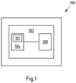
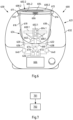
- the Figure 1 shows a schematic view of an embodiment of an accessory 100 for a kitchen appliance (not shown).
- the kitchen appliance is, in particular, a food processor configured for the at least partially automated preparation of food.
- the kitchen appliance comprises a reading arrangement with a reading controller and at least one reading antenna connectable to the reading controller.
- the accessory 100 is, for example, a Varoma, stirring attachment, blade cover, measuring cup, lid, cooking basket, or the like.
- the accessory 100 can be coupled directly or indirectly to the kitchen appliance.
- the accessory 100 comprises, according to the application, a transponder arrangement 102.
- the transponder arrangement 102 can be read, in particular, by the reading antenna at least in the operating position of the accessory 100.
- the transponder arrangement 102 comprises a transponder 104 and an accessory position sensor 108 coupled to the transponder 104.
- the accessory position sensor 108 is preferably an acceleration sensor 108.
- the accessory position sensor 108 is configured to detect at least one accessory position parameter (e.g., vertical axis angle, transverse axis angle, and/or longitudinal axis angle) of the accessory 100.
- the accessory position sensor 108 can preferably be configured to detect the inclination angle of the accessory 100 in relation to the acceleration due to gravity.
- the transponder 104 is preferably an RFID transponder 104.
- the accessory position sensor 108 can provide the (currently) detected accessory position parameter or value to the transponder 104.
- the accessory position sensor 108 can be activated by the Transponder 104 supplies the accessory position sensor 108 with energy based on the received reading field of the reading antenna.
- the accessory position sensor 108 can then provide the (instantaneously) detected accessory position parameter or value to the transponder 104. This is then transmitted by the transponder 104 to the reading arrangement.
- the transponder 104 can encode or manipulate the reading field according to the at least one (instantaneously) detected accessory position parameter. This can be decoded by the reading controller (in particular an RFID reader).
- the transponder 104 can comprise at least one readable memory 101.
- at least one accessory identifier such as a serial number or a Universally Unique Identifier (UUID)
- origin information such as manufacturer identity, time of manufacture, place of manufacture, and/or authentication information
- an accessory type identifier and/or calibration information of the accessory position sensor 108 can be stored in the memory 101. This could be stored before distribution, during or at the end of production, or during a dedicated calibration step.
- Corresponding data can be read out, in particular, by the reading arrangement in addition to the (currently) detected accessory position parameter.
- the Figure 2 shows a schematic view of an embodiment of a kitchen appliance 230 according to the present application.
- the kitchen appliance 230 comprises an appliance base 232, a pot 216, and a lid 200 as an accessory according to the application. It is understood that the pot is also an accessory and, in variants of the application, can have a transponder arrangement according to the application.
- the pot 216 and the lid 200 can, in particular, form a vessel arrangement of the kitchen appliance 230.
- the pot 216 has a circumferential pot wall and a pot base.
- the lid 200 is configured to close an opening of the pot 216.
- This closed state of the vessel arrangement is in the Figure 2
- the cover 200 is located in the Figure 1 in the locked position.
- the lid 200 is (correctly) mechanically locked to the pot 216, i.e., the vessel arrangement is in the locked state.
- this is equivalent to the accessory 200 being in the operating position, i.e., positioned or arranged on the kitchen appliance 230 in a ready-to-use manner.
- the lid 200 is movable relative to the pot 216 between an unlocked position and a (defined) locked position.
- the locking mechanism can be, for example, a bayonet lock or a similar mechanical lock.
- the illustrated kitchen appliance 230 comprises an appliance base 232 with a pot receptacle 234.
- the pot receptacle 234 is configured to receive the pot 216, in particular at least the pot base.
- the pot receptacle 234 corresponds to the pot 216 of the vessel arrangement in such a way that an electrical connection is established between a first lower electrical pot contact 220 and a first electrical base contact 236 of the appliance base 232 and an electrical connection is established between a second lower electrical pot contact 222 and a second electrical base contact 238 of the appliance base 232 when the pot 216 is (correctly) arranged in the pot receptacle 232.
- the kitchen appliance 230 comprises a reading arrangement 221.
- the reading arrangement 221 comprises a reading controller 226, in particular an RFID reader, and a reading antenna 206, in particular an antenna coil.
- the reading controller 226 is connected to the first base contact 236 and the second base contact 238 via an optional filter and matching network 240.
- the reading antenna 206 is presently connected to the first lower pot contact 220 and the second lower pot contact 222.
- the reading controller 226 can apply an antenna signal to the reading antenna 206 so that the reading antenna 206 transmits a reading field.
- the accessory part 200 in the form of the cover 200 comprises a transponder arrangement 202.
- the transponder arrangement 202 can in particular be designed like the transponder arrangement according to Figure 1 be formed so that in order to avoid repetition, the explanations on the Figure 1 is referred to.
- the reading arrangement 221 is particularly configured to read the transponder arrangement 202.
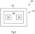
- FIG. 3 shows a schematic view of another embodiment of a kitchen appliance 330 according to the present application. To avoid repetition, only the differences from the previous embodiments are described below, and otherwise reference is made to the previous explanations. In particular, an accessory part has been omitted for the sake of clarity.
- the reading controller 326 of the reading arrangement 321 comprises an evaluation module 370 and a kitchen appliance position sensor 372.
- the kitchen appliance position sensor 372 can be configured to detect a kitchen appliance position parameter.
- the kitchen appliance position sensor 372 can be an acceleration sensor, in particular a 3-axis acceleration sensor.
- the axes can in particular be the transverse axis, longitudinal axis and vertical axis.
- the at least one accessory position parameter can preferably be a (current) angle of inclination of the kitchen appliance 330 (in particular the appliance base 332) in relation to the acceleration due to gravity. For example, from a detected transverse axis angle, longitudinal axis angle and/or vertical axis angle, the The angle of inclination of the kitchen appliance 330 (in particular the appliance base 332) in relation to the acceleration due to gravity can be determined.
- the evaluation module 370 can be configured to determine whether the accessory comprising the transponder arrangement is properly positioned or arranged on the kitchen appliance 330. For this purpose, at least one accessory position parameter can be read from the transponder arrangement and, in particular, the at least one read accessory position parameter can be evaluated.
- the evaluation module 370 can compare the at least one read accessory position parameter (e.g., an aforementioned angle, in particular an angle of inclination relative to the acceleration due to gravity) with the operating position criterion.
- the operating position criterion can define when proper positioning is present (or when not).
- the operating position criterion can define a corresponding angular range.
- the angular range can be based, in particular, on the at least one kitchen appliance position parameter (e.g., the aforementioned angle of inclination).
- the angular range can be a tolerance range around the current angle of inclination.
- the evaluation module 370 can determine that the accessory is properly positioned or arranged on the kitchen appliance 330. If the read angle (value) is not within the angular range, the evaluation module 370 can determine that the accessory is not properly positioned or arranged on the kitchen appliance 330.
- the evaluation module 370 can additionally use further read data in the evaluation, such as an accessory identifier (such as a serial number or a Universally Unique Identifier (UUID)) and/or Origin information (such as manufacturer identity, time of manufacture, place of manufacture and/or authentication information) and/or an accessory type identifier and/or calibration information of the accessory and/or calibration information of the kitchen appliance 330, in particular the appliance base 332.
- an accessory identifier such as a serial number or a Universally Unique Identifier (UUID)
- Origin information such as manufacturer identity, time of manufacture, place of manufacture and/or authentication information
- an accessory type identifier and/or calibration information of the accessory and/or calibration information of the kitchen appliance 330 in particular the appliance base 332.
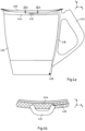
- the Figure 4a shows a schematic side view of an embodiment of a pot 416 of a kitchen appliance according to the present application and the Figure 4c a schematic plan view of an embodiment of a lid 400 of the kitchen appliance according to the present application, structurally corresponding to the pot 416.
- the Figure 4b shows an enlarged section, in particular a top view, of the pot 416 according to Figure 4a .
- the pot 416 is preferably formed partly from metal and partly from plastic.
- a portion 442 can be formed from plastic.
- This portion 442 can also form the handle and, in particular, can have an at least partially, preferably completely, annular portion 443 arranged on the pot rim 403.
- a first upper electrical pot contact 412 is arranged on the upper pot edge 403.
- a second upper electrical pot contact (not shown) is preferably arranged on the opposite side of the upper pot edge 403.
- the first electrical pot connection 418 extends from the first upper electrical pot contact 412, in particular through the section 442, to the first lower pot contact 420.
- the first pot connection 418 can be integrated into the plastic section 442.
- the first lower pot contact 420 is arranged in particular in or on the pot base.
- the further pot connection (not shown) can be designed accordingly.
- the upper first pot contact 412 and the second pot contact are preferably embedded in the annular plastic section 443.
- This section 443 preferably comprises part of the locking mechanism of the vessel assembly.
- the section 443 can have contours for locking the lid 400 to the pot 416 in the defined locking position.
- a first cover contact 411 and a second cover contact 413 are arranged on the cover 400, in particular on the outer cover edge 405.
- the reading antenna 406 of the reading arrangement 421 of the kitchen appliance is, in particular, an antenna coil 406.
- the antenna coil 406 can be formed by at least one winding 409, preferably a plurality of windings 409, as shown.
- the at least one winding 409 can, in particular, be formed from a metal, preferably from copper.
- the at least one turn 409 runs in particular along the cover edge 405 or in the vicinity of the cover edge 405 from the first cover contact 411 to the second cover contact 413.
- the second cover contact 413 is located in particular on a side of the cover edge 405 opposite the first cover contact 411.
- the at least one winding 409 is preferably inserted into the lid base body during production and then provided with a cover (not shown) (preferably made of plastic), which can be attached to the lid base body, for example, by ultrasonic welding.
- the first cover contact 411 and the second cover contact 413 can be arranged on the cover 40 and relative to the upper pot contacts 412, such that an electrical connection between the first cover contact 411 and the The first upper pot contact 412 and an electrical connection between the second lid contact 410 and the second upper pot contact can only be established in the locked position of the lid 400.
- an antenna signal can only be applied to the reading antenna 406 by the reading controller when the lid 400 is in the locked position.
- the circuit is only closed in the locked position.
- the respective connections between the lid contact and pot contact are contact-type connections.
- the respective contacts 411, 412, 413 slide off each other or contact each other. This prevents a deterioration of the contact resistance at the respective contacts 411, 412, 413, since any contaminants adhering to the contacts 411, 412, 413 are scraped off.
- a backing 444 with an elastic material can be provided on the cover contact 411, 413 or pot contact 412.
- the cover 400 further comprises a transponder arrangement 402 as an accessory.
- the transponder arrangement 402 and the reading antenna 406 of the reading arrangement 421 can be arranged in an accessory part.
- the transponder 404 is arranged within range of the antenna coil 406.
- the transponder 408 is surrounded by at least one winding 409. In one embodiment, there may be three or four windings.
- the transponder connected to a previously described accessory position sensor 408 has a second antenna coil 425.
- the transponder arrangement 402 can be adhesively bonded.
- the transponder arrangement 402, in particular the antenna coil 425, can be covered by a cover (not shown), for example, made of plastic.
- a contactless electrical connection can generally also be provided between a lid contact and a pot contact.
- the first cover contact can be formed as a first cover surface element (e.g. by a film made of an electrically conductive material, for example a metal foil) and the second cover contact can be formed as a second cover surface element (e.g. by a film made of an electrically conductive material, for example a metal foil).
- first cover surface element e.g. by a film made of an electrically conductive material, for example a metal foil
- second cover contact can be formed as a second cover surface element (e.g. by a film made of an electrically conductive material, for example a metal foil).
- the first upper pot contact can be formed as a first pot surface element (e.g. by a foil made of an electrically conductive material, for example a metal foil) and the second upper pot contact (e.g. by a foil made of an electrically conductive material, for example a metal foil) can be formed as a second pot surface element.
- first pot surface element e.g. by a foil made of an electrically conductive material, for example a metal foil
- the second upper pot contact e.g. by a foil made of an electrically conductive material, for example a metal foil
- the first lid surface element and the first pot surface element can form a first coupling capacitor.
- the second The cover surface element and the second pot surface element can form a second coupling capacitor.
- the aforementioned surface elements form a respective coupling capacitor only when the cover is in the locked position.
- the antenna signal provided by the reading controller can only be transmitted to the reading antenna (e.g., an antenna coil (schematically indicated)) via the aforementioned coupling capacitors in the locked position.
- the dielectric of the respective coupling capacitor is determined in particular by air and/or the plastic used.
- reference numeral 450 designates the vertical axis of the accessory 400
- reference numeral 452 designates the longitudinal axis of the accessory 400
- reference numeral 454 designates the transverse axis of the accessory 400.
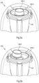
- the Figure 5a shows a schematic view of an embodiment of an accessory 500.1 according to the present application in an operating position and the Figure 5b (compared to Figure 5a ) shows a schematic view of an embodiment of the accessory part 500.1 in a non-operating position.
- the Figure 5b shows a schematic view of an embodiment of the accessory part 500.1 in a non-operating position.
- the accessory 500.1 is linked to the kitchen appliance 530 and is ready for operation.
- the accessory 500.1 is coupled or connected to the lid 500.2 of the kitchen appliance 530.
- the accessory 500.1 is in the operating position.
- Pot 516 and lid 500.2 can, for example, be used as pot and lid of the Figure 4 be educated.
- the evaluation module of a reading arrangement will determine that, for example, the detected angle of inclination in relation to the gravitational acceleration of the accessory 500.1 satisfies the operating position criterion.
- the operating position criterion can be a detected angle of inclination in relation to the gravitational acceleration of the kitchen appliance 530 (or a tolerance range around this angle of inclination).
- the operating position criterion is met in particular when the angle of inclination in relation to the gravitational acceleration of the accessory 500.1 essentially corresponds to the angle of inclination in relation to the gravitational acceleration of the kitchen appliance 500.1, i.e., in particular, lies within the angle range or tolerance range. This means, in particular, that the angle of inclination between the two sensors (within a tolerance range) is equal to zero.
- an accessory type criterion and, if applicable, calibration information can be taken into account.
- at least one of the inclination angles can be corrected or adjusted using the accessory type criterion and/or calibration information.
- the evaluation module can therefore determine the operating position of the accessory part 500.1 based on the read-out accessory position parameter and an operating position criterion.
- the accessory 500.1 is not properly or operationally positioned on the kitchen appliance 530. Rather, the accessory 500.1 lies in the edge area of the lid 500.2 and thus, due to the design and/or structural measures taken on the accessory 500.1 and/or the additional accessory 500.2, is at an angle. The accessory 500.1 is therefore not coupled to the lid 500.2 of the kitchen appliance 530 or is not correctly positioned. In other words, the accessory 500.1 is in a non-operating position. Proper operation is not possible in this position.
- the evaluation module of a reading arrangement will determine that, for example, the detected angle of inclination relative to the acceleration due to gravity of the accessory 500.1 does not meet the operating position criterion.
- the operating position criterion can be a detected angle of inclination relative to the acceleration due to gravity of the kitchen appliance 530 (or a tolerance range around this angle of inclination).
- the operating position criterion is not met in particular if the angle of inclination in relation to the acceleration due to gravity of the accessory part 500.1 does not essentially correspond to the angle of inclination in relation to the acceleration due to gravity of the kitchen appliance 500.1, i.e. in particular if it lies outside the angle range or tolerance range.
- an accessory type criterion and, if applicable, calibration information can be taken into account.
- at least one of the inclination angles can be corrected or adjusted using the accessory type criterion and/or calibration information.
- the evaluation module can therefore determine the non-operating position of the accessory 500.1 based on the read-out accessory position parameter and an operating position criterion.
- FIG. 6 shows a schematic view of another embodiment of a kitchen appliance 630 according to the present application. To avoid repetition, only the differences from the previous embodiments are described below, and otherwise reference is made to the previous explanations.
- the appliance base 632 has a tool drive 660.
- the tool drive 660 is configured to drive or operate an (accessory in the form of) a kitchen appliance tool 662, which can be located in particular in the pot 616.
- a cutting tool 662 is shown as an example of the kitchen appliance tool 662.
- the kitchen base can comprise a control device that controls and monitors the heater integrated in the pot 602.
- an accessory 600.1 in the form of a stirring attachment 600.1 is positioned on or on the kitchen appliance tool 662. As shown, the accessory 600.1 is correctly positioned or, in the present case, coupled to the kitchen appliance tool 662 (and thus to the kitchen appliance 630). In particular, the illustrated accessory 600.1 is in an operating position.
- the kitchen appliance 630 comprises a further accessory 600.2 in the form of a lid 600.2.
- Pot 616 and lid 600.2 can, for example, correspond to the pot and lid of the Figures 4a and 4b be educated.
- the reading controller 626 comprises, in particular, an evaluation module 670 and a kitchen appliance position sensor 672.
- the evaluation module 670 is, in particular, configured to detect or determine the operating position or an operating state of the accessories 600.1, 600.2 based on the data read from the transponder arrangements 602.1, 602.2 (at least the respective currently detected accessory position parameters).
- the lid 600.2 can be moved into the locked position by a user. Once the lid 600.2 is in the locked position, an electrical connection is established between the first lid contact 611 and the first upper pot contact 612, and an electrical connection is established between the second lid contact 613 and the second upper pot contact 614. Once the connections have been established, an antenna signal is applied to the reading antenna 606 by the reading controller 626, so that in particular a reading field is generated and transmitted.
- the transponders 604.1, 604.2 arranged within range receive the reading field and, in particular, extract the instructions contained therein. Based on the instructions, the respective transponder 604.1, 604.2 generates a response. For example, the respective transponder 604.1, 604.2 outputs the respective currently detected accessory position parameters and, optionally, the respective stored data, such as an accessory identifier and/or origin information and/or an accessory type identifier and/or calibration information of the respective accessory position sensor 608.1, 608.2. In particular, the respective transponder 604.1, 604.2 influences the reading field accordingly. This can be detected by the reading controller 626, so that the aforementioned data is read out.
- an operating position or a non-operating position of the accessories 600.1, 600.2 can be determined.
- the device base 632 comprises an enabling module 674.
- the enabling module 674 is configured, in particular, to enable at least one device function, in particular depending on the accessory type of the at least one accessory 600.1, 600.2 (properly) positioned on the device base 632 and/or another accessory.
- the enabling module 674 can, in particular, be communicatively connected to the evaluation module 670. If no properly positioned accessory is detected, the at least one device function can remain blocked.
- the evaluation module 670 can additionally be configured to determine the accessory type based on the read data, in particular the accessory type identifier and a stored accessory type criterion.
- the accessory type criterion can be a previously described assignment table.
- the assignment table can also store at least one device function permitted for each accessory type.
- Exemplary and non-exhaustive kitchen appliance functions or appliance functions are a first cutting function with a first maximum permissible target speed and/or target torque, a further cutting function with a second maximum permissible target speed and/or target torque (different from the first maximum permissible target speed and/or target torque), a first stirring function with a first maximum permissible target speed and/or target torque, a further stirring function with a second maximum permissible target speed and/or target torque (different from the first maximum permissible target speed and/or target torque), a first motor rotation direction, a second opposite motor rotation direction, a first target temperature (or heating output) and/or a first target temperature range (or heating output range) of a heater integrated in the food receiving element, a second target temperature (different from the first target temperature) and/or a second target temperature range (different from the first target temperature range) of a heater integrated in the food receiving element, control programs and/or control program target parameters for certain operations, etc.
- the at least one device function permitted for this accessory type can be released by the release module 674.
- the accessory type and optionally the permitted device function can be determined in particular by comparing the read accessory type identifier with the accessory type identifiers stored in the assignment table.
- the permissible device function includes a maximum permissible drive setpoint parameter value, enabling a device function, in particular, limiting, for example by the enable module 674, the operation of the tool drive 660 to the drive target parameter value stored for this accessory type (e.g. a maximum permissible target speed and/or a maximum permissible torque).
- the kitchen appliance 630 can have a (visual) indicator 666, for example, a display.
- the indicator 666 can be configured to display the identified accessory type.
- an error message for example, if an operating position or a coupling state was detected, but no accessory type could be determined, or if a non-operating position or a non-coupling state was detected
- a notification message for example, a cleaning request
- FIG. 7 shows a diagram of an embodiment of a method according to the present application. The method is used to detect or determine the operating position of an accessory.
- a step 701 the accessory position parameter of the accessory detected by the accessory position sensor is read out by a reading arrangement of the kitchen appliance, as already described.
- an evaluation module of the reading arrangement determines an operating position of the accessory based on the read-out accessory position parameter and an operating position criterion.
Landscapes
- Engineering & Computer Science (AREA)
- Computer Networks & Wireless Communication (AREA)
- Signal Processing (AREA)
- Food Science & Technology (AREA)
- Mechanical Engineering (AREA)
- Computer Hardware Design (AREA)
- Microelectronics & Electronic Packaging (AREA)
- Physics & Mathematics (AREA)
- General Physics & Mathematics (AREA)
- Theoretical Computer Science (AREA)
- Cookers (AREA)
Priority Applications (5)
| Application Number | Priority Date | Filing Date | Title |
|---|---|---|---|
| ES22160537T ES3035689T3 (en) | 2022-03-07 | 2022-03-07 | Accessory for a kitchen appliance |
| PL22160537.1T PL4243293T3 (pl) | 2022-03-07 | 2022-03-07 | Akcesorium do urządzenia kuchennego |
| EP22160537.1A EP4243293B1 (de) | 2022-03-07 | 2022-03-07 | Zubehörteil für ein küchengerät |
| US18/177,325 US20230276998A1 (en) | 2022-03-07 | 2023-03-02 | Accessory for a Kitchen Appliance |
| CN202310203906.2A CN116711972A (zh) | 2022-03-07 | 2023-03-06 | 用于厨房用具的附件 |
Applications Claiming Priority (1)
| Application Number | Priority Date | Filing Date | Title |
|---|---|---|---|
| EP22160537.1A EP4243293B1 (de) | 2022-03-07 | 2022-03-07 | Zubehörteil für ein küchengerät |
Publications (3)
| Publication Number | Publication Date |
|---|---|
| EP4243293A1 EP4243293A1 (de) | 2023-09-13 |
| EP4243293B1 true EP4243293B1 (de) | 2025-05-21 |
| EP4243293C0 EP4243293C0 (de) | 2025-05-21 |
Family
ID=80682764
Family Applications (1)
| Application Number | Title | Priority Date | Filing Date |
|---|---|---|---|
| EP22160537.1A Active EP4243293B1 (de) | 2022-03-07 | 2022-03-07 | Zubehörteil für ein küchengerät |
Country Status (5)
| Country | Link |
|---|---|
| US (1) | US20230276998A1 (pl) |
| EP (1) | EP4243293B1 (pl) |
| CN (1) | CN116711972A (pl) |
| ES (1) | ES3035689T3 (pl) |
| PL (1) | PL4243293T3 (pl) |
Families Citing this family (2)
| Publication number | Priority date | Publication date | Assignee | Title |
|---|---|---|---|---|
| EP4241637B1 (de) * | 2022-03-07 | 2025-05-07 | Vorwerk & Co. Interholding GmbH | Gefässanordnung für ein küchengerät |
| WO2025147746A1 (en) * | 2024-01-12 | 2025-07-17 | Breville Pty Limited | Kitchen device accessory identification system |
Citations (1)
| Publication number | Priority date | Publication date | Assignee | Title |
|---|---|---|---|---|
| CN206496384U (zh) * | 2017-01-03 | 2017-09-15 | 广东格兰仕集团有限公司 | 一种微波炉的安全集成结构 |
Family Cites Families (14)
| Publication number | Priority date | Publication date | Assignee | Title |
|---|---|---|---|---|
| WO2009138893A1 (en) * | 2008-05-15 | 2009-11-19 | Nxp B.V. | Sensor calibration in an rfid tag |
| WO2010052631A2 (en) * | 2008-11-04 | 2010-05-14 | Koninklijke Philips Electronics N.V. | Kitchen device and blending device |
| ES2371809B1 (es) * | 2010-06-18 | 2012-12-04 | Electrodomésticos Taurus, S.L. | Encimera de cocina motorizada y recipiente de cocina utilizable con dicha encimera |
| JP5443332B2 (ja) * | 2010-12-27 | 2014-03-19 | リンナイ株式会社 | ガス炊飯器 |
| ES2393378B1 (es) * | 2011-06-07 | 2013-10-31 | Electrodomésticos Taurus, S.L. | Encimera de cocina con medios de accionamiento giratorio y recipiente de cocina utilizable con dicha encimera |
| FI126325B (en) * | 2014-09-03 | 2016-09-30 | Metso Flow Control Oy | RFID reader method and RFID reader |
| CN105795926B (zh) * | 2014-12-31 | 2018-06-05 | 佛山市顺德区美的电热电器制造有限公司 | 电饭煲的控制方法 |
| US10413131B2 (en) | 2015-04-24 | 2019-09-17 | Vita-Mix Management Corporation | Interlocking blending system |
| EP3172996B1 (en) * | 2015-11-30 | 2021-01-13 | Whirlpool Corporation | Cooking system |
| US11013371B2 (en) * | 2017-03-10 | 2021-05-25 | Vita-Mix Management Corporation | Wireless food processor discs |
| CN208301548U (zh) * | 2017-06-08 | 2019-01-01 | 深圳拓邦股份有限公司 | 一种搅拌机 |
| US12144464B2 (en) * | 2018-06-29 | 2024-11-19 | Breville Pty Limited | Safety system, a method for selecting an operating mode, and a lid for a kitchen device |
| AU2020245708A1 (en) * | 2019-03-25 | 2021-09-23 | Breville Pty Limited | Kitchen device |
| DE102021201800B3 (de) * | 2021-02-25 | 2022-06-15 | BORA - Vertriebs GmbH & Co KG | Tragbares Bediengerät zum Steuern eines Küchengeräts aus unterschiedlichen Bedienpositionen und Küchengerätesystem |
-
2022
- 2022-03-07 PL PL22160537.1T patent/PL4243293T3/pl unknown
- 2022-03-07 ES ES22160537T patent/ES3035689T3/es active Active
- 2022-03-07 EP EP22160537.1A patent/EP4243293B1/de active Active
-
2023
- 2023-03-02 US US18/177,325 patent/US20230276998A1/en active Pending
- 2023-03-06 CN CN202310203906.2A patent/CN116711972A/zh active Pending
Patent Citations (1)
| Publication number | Priority date | Publication date | Assignee | Title |
|---|---|---|---|---|
| CN206496384U (zh) * | 2017-01-03 | 2017-09-15 | 广东格兰仕集团有限公司 | 一种微波炉的安全集成结构 |
Also Published As
| Publication number | Publication date |
|---|---|
| PL4243293T3 (pl) | 2025-07-21 |
| US20230276998A1 (en) | 2023-09-07 |
| CN116711972A (zh) | 2023-09-08 |
| EP4243293A1 (de) | 2023-09-13 |
| EP4243293C0 (de) | 2025-05-21 |
| ES3035689T3 (en) | 2025-09-08 |
Similar Documents
| Publication | Publication Date | Title |
|---|---|---|
| EP4243293B1 (de) | Zubehörteil für ein küchengerät | |
| EP3639942B2 (de) | Pressmaschine mit sensorsystem zur automatisierten erkennung einer pressbackenanordnung | |
| DE102008031378B4 (de) | Gewerbliches Gargerät, insbesondere gewerblicher Heißluftdämpfer | |
| DE60133378T2 (de) | Automatisches herstellungssteuerungssystem | |
| WO2016188959A1 (de) | Chirurgisches behälterinhalt-erfassungssystem | |
| EP3841926B1 (de) | Funktionselement für ein küchengerät, küchengerät sowie verfahren zur datenkommunikation | |
| DE60122473T2 (de) | Identifikationsvorrichtung | |
| EP4241638B1 (de) | Gefässanordnung für ein küchengerät | |
| EP3328204B1 (de) | Vorrichtung mit drahtlosmodul zum bearbeiten eines mediums | |
| EP3420864A1 (de) | Mit sensoren zur ermittlung eines betriebszustandes ausgestattetes zusatzteil, insbesondere messbecher oder abdeckteil einer küchenmaschine | |
| EP3446081B1 (de) | System und verfahren zum automatischen ermitteln des gewichts von nahrungsmitteln | |
| DE102005023468B4 (de) | Gargerät | |
| EP3813486A1 (de) | Verfahren zum betrieb eines kochsystems sowie kochfeld und gargeschirr | |
| DE202014104429U1 (de) | Messer mit einem am Erl angeordneten RFID-Transponder | |
| EP4241637B1 (de) | Gefässanordnung für ein küchengerät | |
| DE202008006868U1 (de) | Chirurgische Antriebseinheit, chirurgisches Instrument und chirurgisches Antriebssystem | |
| DE102011051151A1 (de) | Anordnung zur Überprüfung einer Verschlusslage eines Deckels | |
| AT409328B (de) | Speisenverteilsystem | |
| EP3115758B1 (de) | Abnehmbarer kochsensor | |
| WO2009146691A2 (de) | Dosiervorrichtung und haushaltsmaschine, insbesondere geschirrspülmaschine | |
| EP3201593B1 (de) | Prüfscheibensystem | |
| EP2538377A2 (de) | Verfahren zur Abwickung von Kanban-Aufrägen und RFID-Palettenbox | |
| EP4467041A1 (de) | Aufnahmegefäss für ein küchengerät, küchengerät und verfahren zum betreiben eines küchengeräts | |
| EP4312868A1 (de) | Integrierter rfid-tag in einem handinstrument | |
| DE102015106729B4 (de) | Elektromotorisch betriebene Küchenmaschine |
Legal Events
| Date | Code | Title | Description |
|---|---|---|---|
| PUAI | Public reference made under article 153(3) epc to a published international application that has entered the european phase |
Free format text: ORIGINAL CODE: 0009012 |
|
| STAA | Information on the status of an ep patent application or granted ep patent |
Free format text: STATUS: THE APPLICATION HAS BEEN PUBLISHED |
|
| AK | Designated contracting states |
Kind code of ref document: A1 Designated state(s): AL AT BE BG CH CY CZ DE DK EE ES FI FR GB GR HR HU IE IS IT LI LT LU LV MC MK MT NL NO PL PT RO RS SE SI SK SM TR |
|
| STAA | Information on the status of an ep patent application or granted ep patent |
Free format text: STATUS: REQUEST FOR EXAMINATION WAS MADE |
|
| 17P | Request for examination filed |
Effective date: 20240219 |
|
| RBV | Designated contracting states (corrected) |
Designated state(s): AL AT BE BG CH CY CZ DE DK EE ES FI FR GB GR HR HU IE IS IT LI LT LU LV MC MK MT NL NO PL PT RO RS SE SI SK SM TR |
|
| GRAP | Despatch of communication of intention to grant a patent |
Free format text: ORIGINAL CODE: EPIDOSNIGR1 |
|
| STAA | Information on the status of an ep patent application or granted ep patent |
Free format text: STATUS: GRANT OF PATENT IS INTENDED |
|
| INTG | Intention to grant announced |
Effective date: 20241115 |
|
| GRAS | Grant fee paid |
Free format text: ORIGINAL CODE: EPIDOSNIGR3 |
|
| GRAA | (expected) grant |
Free format text: ORIGINAL CODE: 0009210 |
|
| STAA | Information on the status of an ep patent application or granted ep patent |
Free format text: STATUS: THE PATENT HAS BEEN GRANTED |
|
| AK | Designated contracting states |
Kind code of ref document: B1 Designated state(s): AL AT BE BG CH CY CZ DE DK EE ES FI FR GB GR HR HU IE IS IT LI LT LU LV MC MK MT NL NO PL PT RO RS SE SI SK SM TR |
|
| REG | Reference to a national code |
Ref country code: GB Ref legal event code: FG4D Free format text: NOT ENGLISH |
|
| REG | Reference to a national code |
Ref country code: CH Ref legal event code: EP |
|
| REG | Reference to a national code |
Ref country code: DE Ref legal event code: R096 Ref document number: 502022004002 Country of ref document: DE |
|
| REG | Reference to a national code |
Ref country code: IE Ref legal event code: FG4D Free format text: LANGUAGE OF EP DOCUMENT: GERMAN |
|
| U01 | Request for unitary effect filed |
Effective date: 20250603 |
|
| U07 | Unitary effect registered |
Designated state(s): AT BE BG DE DK EE FI FR IT LT LU LV MT NL PT RO SE SI Effective date: 20250611 |
|
| REG | Reference to a national code |
Ref country code: ES Ref legal event code: FG2A Ref document number: 3035689 Country of ref document: ES Kind code of ref document: T3 Effective date: 20250908 |
|
| PG25 | Lapsed in a contracting state [announced via postgrant information from national office to epo] |
Ref country code: GR Free format text: LAPSE BECAUSE OF FAILURE TO SUBMIT A TRANSLATION OF THE DESCRIPTION OR TO PAY THE FEE WITHIN THE PRESCRIBED TIME-LIMIT Effective date: 20250822 Ref country code: NO Free format text: LAPSE BECAUSE OF FAILURE TO SUBMIT A TRANSLATION OF THE DESCRIPTION OR TO PAY THE FEE WITHIN THE PRESCRIBED TIME-LIMIT Effective date: 20250821 |
|
| PG25 | Lapsed in a contracting state [announced via postgrant information from national office to epo] |
Ref country code: HR Free format text: LAPSE BECAUSE OF FAILURE TO SUBMIT A TRANSLATION OF THE DESCRIPTION OR TO PAY THE FEE WITHIN THE PRESCRIBED TIME-LIMIT Effective date: 20250521 |
|
| PG25 | Lapsed in a contracting state [announced via postgrant information from national office to epo] |
Ref country code: RS Free format text: LAPSE BECAUSE OF FAILURE TO SUBMIT A TRANSLATION OF THE DESCRIPTION OR TO PAY THE FEE WITHIN THE PRESCRIBED TIME-LIMIT Effective date: 20250821 |
|
| PG25 | Lapsed in a contracting state [announced via postgrant information from national office to epo] |
Ref country code: IS Free format text: LAPSE BECAUSE OF FAILURE TO SUBMIT A TRANSLATION OF THE DESCRIPTION OR TO PAY THE FEE WITHIN THE PRESCRIBED TIME-LIMIT Effective date: 20250921 |
|
| PG25 | Lapsed in a contracting state [announced via postgrant information from national office to epo] |
Ref country code: SM Free format text: LAPSE BECAUSE OF FAILURE TO SUBMIT A TRANSLATION OF THE DESCRIPTION OR TO PAY THE FEE WITHIN THE PRESCRIBED TIME-LIMIT Effective date: 20250521 |
|
| PG25 | Lapsed in a contracting state [announced via postgrant information from national office to epo] |
Ref country code: CZ Free format text: LAPSE BECAUSE OF FAILURE TO SUBMIT A TRANSLATION OF THE DESCRIPTION OR TO PAY THE FEE WITHIN THE PRESCRIBED TIME-LIMIT Effective date: 20250521 |
|
| PG25 | Lapsed in a contracting state [announced via postgrant information from national office to epo] |
Ref country code: SK Free format text: LAPSE BECAUSE OF FAILURE TO SUBMIT A TRANSLATION OF THE DESCRIPTION OR TO PAY THE FEE WITHIN THE PRESCRIBED TIME-LIMIT Effective date: 20250521 |