EP4243096A2 - Système de source de lumière blanche - Google Patents
Système de source de lumière blanche Download PDFInfo
- Publication number
- EP4243096A2 EP4243096A2 EP23174762.7A EP23174762A EP4243096A2 EP 4243096 A2 EP4243096 A2 EP 4243096A2 EP 23174762 A EP23174762 A EP 23174762A EP 4243096 A2 EP4243096 A2 EP 4243096A2
- Authority
- EP
- European Patent Office
- Prior art keywords
- light source
- white light
- phosphor
- light emission
- source system
- Prior art date
- Legal status (The legal status is an assumption and is not a legal conclusion. Google has not performed a legal analysis and makes no representation as to the accuracy of the status listed.)
- Pending
Links
- OAICVXFJPJFONN-UHFFFAOYSA-N Phosphorus Chemical compound [P] OAICVXFJPJFONN-UHFFFAOYSA-N 0.000 claims abstract description 285
- 238000000295 emission spectrum Methods 0.000 claims description 155
- 230000005457 Black-body radiation Effects 0.000 claims description 101
- 238000001228 spectrum Methods 0.000 claims description 93
- 229920005989 resin Polymers 0.000 claims description 76
- 239000011347 resin Substances 0.000 claims description 76
- 230000003595 spectral effect Effects 0.000 claims description 62
- 239000000843 powder Substances 0.000 claims description 58
- 230000002596 correlated effect Effects 0.000 claims description 49
- 229920002050 silicone resin Polymers 0.000 claims description 41
- 230000014509 gene expression Effects 0.000 claims description 31
- 239000002245 particle Substances 0.000 claims description 29
- 230000000875 corresponding effect Effects 0.000 claims description 26
- 229910010272 inorganic material Inorganic materials 0.000 claims description 19
- 239000000203 mixture Substances 0.000 claims description 14
- 150000002484 inorganic compounds Chemical class 0.000 claims description 9
- 229910052684 Cerium Inorganic materials 0.000 claims description 5
- ZMIGMASIKSOYAM-UHFFFAOYSA-N cerium Chemical compound [Ce][Ce][Ce][Ce][Ce][Ce][Ce][Ce][Ce][Ce][Ce][Ce][Ce][Ce][Ce][Ce][Ce][Ce][Ce][Ce][Ce][Ce][Ce][Ce][Ce][Ce][Ce][Ce][Ce][Ce][Ce][Ce][Ce][Ce][Ce][Ce][Ce][Ce] ZMIGMASIKSOYAM-UHFFFAOYSA-N 0.000 claims 1
- 238000005286 illumination Methods 0.000 abstract description 51
- 239000000463 material Substances 0.000 abstract description 36
- 238000009877 rendering Methods 0.000 abstract description 36
- 238000010422 painting Methods 0.000 abstract description 12
- 230000002411 adverse Effects 0.000 abstract 1
- 239000010410 layer Substances 0.000 description 168
- 239000000758 substrate Substances 0.000 description 62
- 230000000052 comparative effect Effects 0.000 description 48
- 229910052693 Europium Inorganic materials 0.000 description 44
- PNEYBMLMFCGWSK-UHFFFAOYSA-N aluminium oxide Inorganic materials [O-2].[O-2].[O-2].[Al+3].[Al+3] PNEYBMLMFCGWSK-UHFFFAOYSA-N 0.000 description 38
- VYPSYNLAJGMNEJ-UHFFFAOYSA-N Silicium dioxide Chemical compound O=[Si]=O VYPSYNLAJGMNEJ-UHFFFAOYSA-N 0.000 description 37
- -1 europium activated strontium Chemical class 0.000 description 33
- 238000010521 absorption reaction Methods 0.000 description 31
- 238000012937 correction Methods 0.000 description 31
- OGPBJKLSAFTDLK-UHFFFAOYSA-N europium atom Chemical compound [Eu] OGPBJKLSAFTDLK-UHFFFAOYSA-N 0.000 description 30
- 239000010408 film Substances 0.000 description 28
- 239000003086 colorant Substances 0.000 description 26
- 238000009826 distribution Methods 0.000 description 25
- 239000010419 fine particle Substances 0.000 description 23
- 238000000034 method Methods 0.000 description 23
- 235000019557 luminance Nutrition 0.000 description 22
- XLYOFNOQVPJJNP-UHFFFAOYSA-N water Substances O XLYOFNOQVPJJNP-UHFFFAOYSA-N 0.000 description 19
- 230000000694 effects Effects 0.000 description 17
- 101100129500 Caenorhabditis elegans max-2 gene Proteins 0.000 description 14
- 238000011156 evaluation Methods 0.000 description 14
- 229910021485 fumed silica Inorganic materials 0.000 description 14
- 238000005259 measurement Methods 0.000 description 12
- 241000282412 Homo Species 0.000 description 11
- 238000010586 diagram Methods 0.000 description 10
- 239000011147 inorganic material Substances 0.000 description 10
- 238000004364 calculation method Methods 0.000 description 9
- 230000007423 decrease Effects 0.000 description 9
- 238000000695 excitation spectrum Methods 0.000 description 9
- 238000002474 experimental method Methods 0.000 description 9
- 150000004762 orthosilicates Chemical class 0.000 description 9
- XLOMVQKBTHCTTD-UHFFFAOYSA-N Zinc monoxide Chemical compound [Zn]=O XLOMVQKBTHCTTD-UHFFFAOYSA-N 0.000 description 8
- 239000000377 silicon dioxide Substances 0.000 description 8
- 239000002002 slurry Substances 0.000 description 8
- 229910052782 aluminium Inorganic materials 0.000 description 7
- 230000009931 harmful effect Effects 0.000 description 7
- 230000008447 perception Effects 0.000 description 7
- XAGFODPZIPBFFR-UHFFFAOYSA-N aluminium Chemical compound [Al] XAGFODPZIPBFFR-UHFFFAOYSA-N 0.000 description 6
- 230000015556 catabolic process Effects 0.000 description 6
- 238000006731 degradation reaction Methods 0.000 description 6
- 230000005284 excitation Effects 0.000 description 6
- 239000002223 garnet Substances 0.000 description 6
- RVTZCBVAJQQJTK-UHFFFAOYSA-N oxygen(2-);zirconium(4+) Chemical compound [O-2].[O-2].[Zr+4] RVTZCBVAJQQJTK-UHFFFAOYSA-N 0.000 description 6
- 239000000049 pigment Substances 0.000 description 6
- 229910052761 rare earth metal Inorganic materials 0.000 description 6
- 150000002910 rare earth metals Chemical class 0.000 description 6
- 239000010409 thin film Substances 0.000 description 6
- 229910001928 zirconium oxide Inorganic materials 0.000 description 6
- 230000027288 circadian rhythm Effects 0.000 description 5
- DXNVUKXMTZHOTP-UHFFFAOYSA-N dialuminum;dimagnesium;barium(2+);oxygen(2-) Chemical class [O-2].[O-2].[O-2].[O-2].[O-2].[O-2].[O-2].[Mg+2].[Mg+2].[Al+3].[Al+3].[Ba+2].[Ba+2] DXNVUKXMTZHOTP-UHFFFAOYSA-N 0.000 description 5
- 239000000428 dust Substances 0.000 description 5
- 239000010931 gold Substances 0.000 description 5
- 230000006872 improvement Effects 0.000 description 5
- 229910052748 manganese Inorganic materials 0.000 description 5
- 239000011572 manganese Substances 0.000 description 5
- 229910052814 silicon oxide Inorganic materials 0.000 description 5
- 238000012360 testing method Methods 0.000 description 5
- GWEVSGVZZGPLCZ-UHFFFAOYSA-N Titan oxide Chemical compound O=[Ti]=O GWEVSGVZZGPLCZ-UHFFFAOYSA-N 0.000 description 4
- GWXLDORMOJMVQZ-UHFFFAOYSA-N cerium Chemical compound [Ce] GWXLDORMOJMVQZ-UHFFFAOYSA-N 0.000 description 4
- 239000004020 conductor Substances 0.000 description 4
- 230000003247 decreasing effect Effects 0.000 description 4
- 238000007667 floating Methods 0.000 description 4
- 239000002356 single layer Substances 0.000 description 4
- OGIDPMRJRNCKJF-UHFFFAOYSA-N titanium oxide Inorganic materials [Ti]=O OGIDPMRJRNCKJF-UHFFFAOYSA-N 0.000 description 4
- 239000011787 zinc oxide Substances 0.000 description 4
- 101100083446 Danio rerio plekhh1 gene Proteins 0.000 description 3
- 238000000149 argon plasma sintering Methods 0.000 description 3
- 230000008859 change Effects 0.000 description 3
- 239000000470 constituent Substances 0.000 description 3
- 230000001276 controlling effect Effects 0.000 description 3
- 230000002950 deficient Effects 0.000 description 3
- 230000006870 function Effects 0.000 description 3
- 239000011521 glass Substances 0.000 description 3
- 229910052751 metal Inorganic materials 0.000 description 3
- 239000002184 metal Substances 0.000 description 3
- TWNQGVIAIRXVLR-UHFFFAOYSA-N oxo(oxoalumanyloxy)alumane Chemical compound O=[Al]O[Al]=O TWNQGVIAIRXVLR-UHFFFAOYSA-N 0.000 description 3
- IBIRZFNPWYRWOG-UHFFFAOYSA-N phosphane;phosphoric acid Chemical compound P.OP(O)(O)=O IBIRZFNPWYRWOG-UHFFFAOYSA-N 0.000 description 3
- SMKQIOCKGHFKQZ-UHFFFAOYSA-N phosphanylidynecerium Chemical compound [Ce]#P SMKQIOCKGHFKQZ-UHFFFAOYSA-N 0.000 description 3
- 230000005855 radiation Effects 0.000 description 3
- 230000009467 reduction Effects 0.000 description 3
- 210000001525 retina Anatomy 0.000 description 3
- 230000035807 sensation Effects 0.000 description 3
- 235000019615 sensations Nutrition 0.000 description 3
- FNWBQFMGIFLWII-UHFFFAOYSA-N strontium aluminate Chemical class [O-2].[O-2].[O-2].[O-2].[O-2].[Al+3].[Al+3].[Sr+2].[Sr+2] FNWBQFMGIFLWII-UHFFFAOYSA-N 0.000 description 3
- CURLTUGMZLYLDI-UHFFFAOYSA-N Carbon dioxide Chemical compound O=C=O CURLTUGMZLYLDI-UHFFFAOYSA-N 0.000 description 2
- 239000004593 Epoxy Substances 0.000 description 2
- PWHULOQIROXLJO-UHFFFAOYSA-N Manganese Chemical compound [Mn] PWHULOQIROXLJO-UHFFFAOYSA-N 0.000 description 2
- 239000008119 colloidal silica Substances 0.000 description 2
- 239000013078 crystal Substances 0.000 description 2
- 238000005520 cutting process Methods 0.000 description 2
- 230000007812 deficiency Effects 0.000 description 2
- 238000000151 deposition Methods 0.000 description 2
- 230000008020 evaporation Effects 0.000 description 2
- 238000001704 evaporation Methods 0.000 description 2
- 230000001747 exhibiting effect Effects 0.000 description 2
- 239000000284 extract Substances 0.000 description 2
- 238000005562 fading Methods 0.000 description 2
- PCHJSUWPFVWCPO-UHFFFAOYSA-N gold Chemical compound [Au] PCHJSUWPFVWCPO-UHFFFAOYSA-N 0.000 description 2
- 229910052737 gold Inorganic materials 0.000 description 2
- 238000010438 heat treatment Methods 0.000 description 2
- 230000001788 irregular Effects 0.000 description 2
- 238000004519 manufacturing process Methods 0.000 description 2
- 239000011159 matrix material Substances 0.000 description 2
- 230000003287 optical effect Effects 0.000 description 2
- 230000002265 prevention Effects 0.000 description 2
- 239000011164 primary particle Substances 0.000 description 2
- 238000007639 printing Methods 0.000 description 2
- 230000035945 sensitivity Effects 0.000 description 2
- MCSXGCZMEPXKIW-UHFFFAOYSA-N 3-hydroxy-4-[(4-methyl-2-nitrophenyl)diazenyl]-N-(3-nitrophenyl)naphthalene-2-carboxamide Chemical group Cc1ccc(N=Nc2c(O)c(cc3ccccc23)C(=O)Nc2cccc(c2)[N+]([O-])=O)c(c1)[N+]([O-])=O MCSXGCZMEPXKIW-UHFFFAOYSA-N 0.000 description 1
- 229910002704 AlGaN Inorganic materials 0.000 description 1
- 238000012935 Averaging Methods 0.000 description 1
- 229910052581 Si3N4 Inorganic materials 0.000 description 1
- 230000003044 adaptive effect Effects 0.000 description 1
- JNDMLEXHDPKVFC-UHFFFAOYSA-N aluminum;oxygen(2-);yttrium(3+) Chemical class [O-2].[O-2].[O-2].[Al+3].[Y+3] JNDMLEXHDPKVFC-UHFFFAOYSA-N 0.000 description 1
- 208000003464 asthenopia Diseases 0.000 description 1
- JRPBQTZRNDNNOP-UHFFFAOYSA-N barium titanate Chemical compound [Ba+2].[Ba+2].[O-][Ti]([O-])([O-])[O-] JRPBQTZRNDNNOP-UHFFFAOYSA-N 0.000 description 1
- 229910002113 barium titanate Inorganic materials 0.000 description 1
- 239000011230 binding agent Substances 0.000 description 1
- 229910052799 carbon Inorganic materials 0.000 description 1
- 229910002092 carbon dioxide Inorganic materials 0.000 description 1
- 239000001569 carbon dioxide Substances 0.000 description 1
- 229910000420 cerium oxide Inorganic materials 0.000 description 1
- 239000011248 coating agent Substances 0.000 description 1
- 238000000576 coating method Methods 0.000 description 1
- 238000004737 colorimetric analysis Methods 0.000 description 1
- 238000012790 confirmation Methods 0.000 description 1
- 230000008094 contradictory effect Effects 0.000 description 1
- PMHQVHHXPFUNSP-UHFFFAOYSA-M copper(1+);methylsulfanylmethane;bromide Chemical compound Br[Cu].CSC PMHQVHHXPFUNSP-UHFFFAOYSA-M 0.000 description 1
- 230000007797 corrosion Effects 0.000 description 1
- 238000005260 corrosion Methods 0.000 description 1
- 230000008021 deposition Effects 0.000 description 1
- 238000013461 design Methods 0.000 description 1
- 238000001514 detection method Methods 0.000 description 1
- 239000007772 electrode material Substances 0.000 description 1
- 230000007613 environmental effect Effects 0.000 description 1
- 239000003822 epoxy resin Substances 0.000 description 1
- 230000004438 eyesight Effects 0.000 description 1
- 238000010304 firing Methods 0.000 description 1
- 230000004907 flux Effects 0.000 description 1
- 230000005484 gravity Effects 0.000 description 1
- 231100001261 hazardous Toxicity 0.000 description 1
- 238000009413 insulation Methods 0.000 description 1
- 238000011835 investigation Methods 0.000 description 1
- 230000031700 light absorption Effects 0.000 description 1
- 230000007246 mechanism Effects 0.000 description 1
- 229910044991 metal oxide Inorganic materials 0.000 description 1
- 150000004706 metal oxides Chemical class 0.000 description 1
- 210000003205 muscle Anatomy 0.000 description 1
- BMMGVYCKOGBVEV-UHFFFAOYSA-N oxo(oxoceriooxy)cerium Chemical compound [Ce]=O.O=[Ce]=O BMMGVYCKOGBVEV-UHFFFAOYSA-N 0.000 description 1
- 229910052763 palladium Inorganic materials 0.000 description 1
- 230000002093 peripheral effect Effects 0.000 description 1
- UXXSRDYSXZIJEN-UHFFFAOYSA-N phosphanylidyneeuropium Chemical compound [Eu]#P UXXSRDYSXZIJEN-UHFFFAOYSA-N 0.000 description 1
- 238000007747 plating Methods 0.000 description 1
- 229910052697 platinum Inorganic materials 0.000 description 1
- 229920000647 polyepoxide Polymers 0.000 description 1
- 210000001747 pupil Anatomy 0.000 description 1
- 229910052707 ruthenium Inorganic materials 0.000 description 1
- 238000007789 sealing Methods 0.000 description 1
- 239000004065 semiconductor Substances 0.000 description 1
- HQVNEWCFYHHQES-UHFFFAOYSA-N silicon nitride Chemical compound N12[Si]34N5[Si]62N3[Si]51N64 HQVNEWCFYHHQES-UHFFFAOYSA-N 0.000 description 1
- 229910052709 silver Inorganic materials 0.000 description 1
- 229910000679 solder Inorganic materials 0.000 description 1
- 210000005070 sphincter Anatomy 0.000 description 1
- 239000000126 substance Substances 0.000 description 1
- 230000001629 suppression Effects 0.000 description 1
- 229920001187 thermosetting polymer Polymers 0.000 description 1
- WFKWXMTUELFFGS-UHFFFAOYSA-N tungsten Chemical compound [W] WFKWXMTUELFFGS-UHFFFAOYSA-N 0.000 description 1
- 229910052721 tungsten Inorganic materials 0.000 description 1
- 239000010937 tungsten Substances 0.000 description 1
- 239000011882 ultra-fine particle Substances 0.000 description 1
- 230000016776 visual perception Effects 0.000 description 1
Images


Classifications
-
- H—ELECTRICITY
- H01—ELECTRIC ELEMENTS
- H01L—SEMICONDUCTOR DEVICES NOT COVERED BY CLASS H10
- H01L33/00—Semiconductor devices having potential barriers specially adapted for light emission; Processes or apparatus specially adapted for the manufacture or treatment thereof or of parts thereof; Details thereof
- H01L33/48—Semiconductor devices having potential barriers specially adapted for light emission; Processes or apparatus specially adapted for the manufacture or treatment thereof or of parts thereof; Details thereof characterised by the semiconductor body packages
- H01L33/50—Wavelength conversion elements
- H01L33/507—Wavelength conversion elements the elements being in intimate contact with parts other than the semiconductor body or integrated with parts other than the semiconductor body
-
- H—ELECTRICITY
- H01—ELECTRIC ELEMENTS
- H01L—SEMICONDUCTOR DEVICES NOT COVERED BY CLASS H10
- H01L33/00—Semiconductor devices having potential barriers specially adapted for light emission; Processes or apparatus specially adapted for the manufacture or treatment thereof or of parts thereof; Details thereof
- H01L33/48—Semiconductor devices having potential barriers specially adapted for light emission; Processes or apparatus specially adapted for the manufacture or treatment thereof or of parts thereof; Details thereof characterised by the semiconductor body packages
- H01L33/50—Wavelength conversion elements
-
- H—ELECTRICITY
- H01—ELECTRIC ELEMENTS
- H01L—SEMICONDUCTOR DEVICES NOT COVERED BY CLASS H10
- H01L25/00—Assemblies consisting of a plurality of individual semiconductor or other solid state devices ; Multistep manufacturing processes thereof
- H01L25/03—Assemblies consisting of a plurality of individual semiconductor or other solid state devices ; Multistep manufacturing processes thereof all the devices being of a type provided for in the same subgroup of groups H01L27/00 - H01L33/00, or in a single subclass of H10K, H10N, e.g. assemblies of rectifier diodes
- H01L25/04—Assemblies consisting of a plurality of individual semiconductor or other solid state devices ; Multistep manufacturing processes thereof all the devices being of a type provided for in the same subgroup of groups H01L27/00 - H01L33/00, or in a single subclass of H10K, H10N, e.g. assemblies of rectifier diodes the devices not having separate containers
- H01L25/075—Assemblies consisting of a plurality of individual semiconductor or other solid state devices ; Multistep manufacturing processes thereof all the devices being of a type provided for in the same subgroup of groups H01L27/00 - H01L33/00, or in a single subclass of H10K, H10N, e.g. assemblies of rectifier diodes the devices not having separate containers the devices being of a type provided for in group H01L33/00
- H01L25/0753—Assemblies consisting of a plurality of individual semiconductor or other solid state devices ; Multistep manufacturing processes thereof all the devices being of a type provided for in the same subgroup of groups H01L27/00 - H01L33/00, or in a single subclass of H10K, H10N, e.g. assemblies of rectifier diodes the devices not having separate containers the devices being of a type provided for in group H01L33/00 the devices being arranged next to each other
-
- F—MECHANICAL ENGINEERING; LIGHTING; HEATING; WEAPONS; BLASTING
- F21—LIGHTING
- F21S—NON-PORTABLE LIGHTING DEVICES; SYSTEMS THEREOF; VEHICLE LIGHTING DEVICES SPECIALLY ADAPTED FOR VEHICLE EXTERIORS
- F21S2/00—Systems of lighting devices, not provided for in main groups F21S4/00 - F21S10/00 or F21S19/00, e.g. of modular construction
-
- H—ELECTRICITY
- H01—ELECTRIC ELEMENTS
- H01L—SEMICONDUCTOR DEVICES NOT COVERED BY CLASS H10
- H01L27/00—Devices consisting of a plurality of semiconductor or other solid-state components formed in or on a common substrate
- H01L27/15—Devices consisting of a plurality of semiconductor or other solid-state components formed in or on a common substrate including semiconductor components having potential barriers, specially adapted for light emission
- H01L27/153—Devices consisting of a plurality of semiconductor or other solid-state components formed in or on a common substrate including semiconductor components having potential barriers, specially adapted for light emission in a repetitive configuration, e.g. LED bars
- H01L27/156—Devices consisting of a plurality of semiconductor or other solid-state components formed in or on a common substrate including semiconductor components having potential barriers, specially adapted for light emission in a repetitive configuration, e.g. LED bars two-dimensional arrays
-
- H—ELECTRICITY
- H01—ELECTRIC ELEMENTS
- H01L—SEMICONDUCTOR DEVICES NOT COVERED BY CLASS H10
- H01L33/00—Semiconductor devices having potential barriers specially adapted for light emission; Processes or apparatus specially adapted for the manufacture or treatment thereof or of parts thereof; Details thereof
- H01L33/48—Semiconductor devices having potential barriers specially adapted for light emission; Processes or apparatus specially adapted for the manufacture or treatment thereof or of parts thereof; Details thereof characterised by the semiconductor body packages
- H01L33/50—Wavelength conversion elements
- H01L33/501—Wavelength conversion elements characterised by the materials, e.g. binder
- H01L33/502—Wavelength conversion materials
- H01L33/504—Elements with two or more wavelength conversion materials
-
- H—ELECTRICITY
- H01—ELECTRIC ELEMENTS
- H01L—SEMICONDUCTOR DEVICES NOT COVERED BY CLASS H10
- H01L33/00—Semiconductor devices having potential barriers specially adapted for light emission; Processes or apparatus specially adapted for the manufacture or treatment thereof or of parts thereof; Details thereof
- H01L33/48—Semiconductor devices having potential barriers specially adapted for light emission; Processes or apparatus specially adapted for the manufacture or treatment thereof or of parts thereof; Details thereof characterised by the semiconductor body packages
- H01L33/50—Wavelength conversion elements
- H01L33/505—Wavelength conversion elements characterised by the shape, e.g. plate or foil
-
- H—ELECTRICITY
- H01—ELECTRIC ELEMENTS
- H01L—SEMICONDUCTOR DEVICES NOT COVERED BY CLASS H10
- H01L33/00—Semiconductor devices having potential barriers specially adapted for light emission; Processes or apparatus specially adapted for the manufacture or treatment thereof or of parts thereof; Details thereof
- H01L33/48—Semiconductor devices having potential barriers specially adapted for light emission; Processes or apparatus specially adapted for the manufacture or treatment thereof or of parts thereof; Details thereof characterised by the semiconductor body packages
- H01L33/52—Encapsulations
- H01L33/54—Encapsulations having a particular shape
-
- H—ELECTRICITY
- H01—ELECTRIC ELEMENTS
- H01L—SEMICONDUCTOR DEVICES NOT COVERED BY CLASS H10
- H01L33/00—Semiconductor devices having potential barriers specially adapted for light emission; Processes or apparatus specially adapted for the manufacture or treatment thereof or of parts thereof; Details thereof
- H01L33/48—Semiconductor devices having potential barriers specially adapted for light emission; Processes or apparatus specially adapted for the manufacture or treatment thereof or of parts thereof; Details thereof characterised by the semiconductor body packages
- H01L33/52—Encapsulations
- H01L33/56—Materials, e.g. epoxy or silicone resin
-
- H—ELECTRICITY
- H05—ELECTRIC TECHNIQUES NOT OTHERWISE PROVIDED FOR
- H05B—ELECTRIC HEATING; ELECTRIC LIGHT SOURCES NOT OTHERWISE PROVIDED FOR; CIRCUIT ARRANGEMENTS FOR ELECTRIC LIGHT SOURCES, IN GENERAL
- H05B45/00—Circuit arrangements for operating light-emitting diodes [LED]
- H05B45/10—Controlling the intensity of the light
-
- H—ELECTRICITY
- H05—ELECTRIC TECHNIQUES NOT OTHERWISE PROVIDED FOR
- H05B—ELECTRIC HEATING; ELECTRIC LIGHT SOURCES NOT OTHERWISE PROVIDED FOR; CIRCUIT ARRANGEMENTS FOR ELECTRIC LIGHT SOURCES, IN GENERAL
- H05B45/00—Circuit arrangements for operating light-emitting diodes [LED]
- H05B45/20—Controlling the colour of the light
-
- H—ELECTRICITY
- H05—ELECTRIC TECHNIQUES NOT OTHERWISE PROVIDED FOR
- H05B—ELECTRIC HEATING; ELECTRIC LIGHT SOURCES NOT OTHERWISE PROVIDED FOR; CIRCUIT ARRANGEMENTS FOR ELECTRIC LIGHT SOURCES, IN GENERAL
- H05B47/00—Circuit arrangements for operating light sources in general, i.e. where the type of light source is not relevant
- H05B47/10—Controlling the light source
- H05B47/16—Controlling the light source by timing means
-
- F—MECHANICAL ENGINEERING; LIGHTING; HEATING; WEAPONS; BLASTING
- F21—LIGHTING
- F21W—INDEXING SCHEME ASSOCIATED WITH SUBCLASSES F21K, F21L, F21S and F21V, RELATING TO USES OR APPLICATIONS OF LIGHTING DEVICES OR SYSTEMS
- F21W2131/00—Use or application of lighting devices or systems not provided for in codes F21W2102/00-F21W2121/00
- F21W2131/40—Lighting for industrial, commercial, recreational or military use
- F21W2131/405—Lighting for industrial, commercial, recreational or military use for shop-windows or displays
-
- F—MECHANICAL ENGINEERING; LIGHTING; HEATING; WEAPONS; BLASTING
- F21—LIGHTING
- F21Y—INDEXING SCHEME ASSOCIATED WITH SUBCLASSES F21K, F21L, F21S and F21V, RELATING TO THE FORM OR THE KIND OF THE LIGHT SOURCES OR OF THE COLOUR OF THE LIGHT EMITTED
- F21Y2113/00—Combination of light sources
- F21Y2113/10—Combination of light sources of different colours
- F21Y2113/13—Combination of light sources of different colours comprising an assembly of point-like light sources
-
- F—MECHANICAL ENGINEERING; LIGHTING; HEATING; WEAPONS; BLASTING
- F21—LIGHTING
- F21Y—INDEXING SCHEME ASSOCIATED WITH SUBCLASSES F21K, F21L, F21S and F21V, RELATING TO THE FORM OR THE KIND OF THE LIGHT SOURCES OR OF THE COLOUR OF THE LIGHT EMITTED
- F21Y2115/00—Light-generating elements of semiconductor light sources
- F21Y2115/10—Light-emitting diodes [LED]
-
- Y—GENERAL TAGGING OF NEW TECHNOLOGICAL DEVELOPMENTS; GENERAL TAGGING OF CROSS-SECTIONAL TECHNOLOGIES SPANNING OVER SEVERAL SECTIONS OF THE IPC; TECHNICAL SUBJECTS COVERED BY FORMER USPC CROSS-REFERENCE ART COLLECTIONS [XRACs] AND DIGESTS
- Y02—TECHNOLOGIES OR APPLICATIONS FOR MITIGATION OR ADAPTATION AGAINST CLIMATE CHANGE
- Y02B—CLIMATE CHANGE MITIGATION TECHNOLOGIES RELATED TO BUILDINGS, e.g. HOUSING, HOUSE APPLIANCES OR RELATED END-USER APPLICATIONS
- Y02B20/00—Energy efficient lighting technologies, e.g. halogen lamps or gas discharge lamps
- Y02B20/40—Control techniques providing energy savings, e.g. smart controller or presence detection
Definitions
- the present invention relates to a white light source and a white light source system for use in illumination in which natural light equivalent to sunlight is required, for example, illumination for articles on exhibition in an art museum or the like, illumination for patients who are forced to stay for long periods in a hospital or the like, and illumination in houses and offices where high color rendering is required.
- the colors that the works have are one of the most important characteristics.
- a painting or a pot itself does not emit light.
- the illumination at a time of appreciating an article on exhibition is as important in meaning as the article itself.
- the reason for this is that a person who appreciates the article on exhibition observes that portion of the visible light radiated from an illumination light source that is reflected by the surface of the article.
- the most desirable light source for this purpose of illumination is sunlight.
- sunlight is composed of consecutive wavelength components of light
- the sunlight includes, substantially equally, all light components of visible light wavelengths from 400 nm to 780 nm, and can reproduce all colors existing in nature as original colors inherent to substances in nature.
- precious works of art, such as paintings are not appreciated in an outdoor bright space, while such works of art are directly exposed to sunlight.
- the reason why the works of art are stored in a specific place such as an art museum and are appreciated is, in part, because it is necessary to protect them from accidents such as by the weather and sealing. However, a more important reason is that it is necessary to protect the works of art from a great quantity of irradiation.
- sunlight includes the visible light of all wavelengths, and also includes emission light components other than visible light, such as ultraviolet and infrared.
- emission light components other than visible light
- ultraviolet and infrared since ultraviolet is stronger in energy than visible light, direct exposure to sunlight promotes fading and embrittlement of historic paintings, etc.
- an artificial light source is needed.
- the artificial light source is required to be able to reproduce sunlight as correctly as possible, in addition to having such convenient features of artificial light that the amount of light is adjustable and the amount of ultraviolet is reduced as much as possible.
- LED light-emitting diode
- the LED has a long lifetime and can achieve energy saving.
- LED illumination is rapidly gaining in popularity in the market.
- white light was obtained by combining a blue light emitting LED and a yellow light emitting phosphor, and only unnatural white which lacks in warmth could be reproduced.
- various improvements have been made to combinations of LEDs and phosphors. As a result, some white light sources that can reproduce sunlight have been developed.
- Patent document 1 discloses an invention relating to a white light source having the same light emission spectrum as sunlight. Sunlights with different color temperatures are reproduced with blackbody radiation spectra of the same color temperatures. In this invention, a white light source can be obtained which reproduces light close to sunlight of various color temperatures which vary with time, not only with respect to apparent white light but also with respect to the spectrum shape.
- Patent document 2 discloses an invention relating to an illumination system using a white light source, and relates to office illumination or the like, with the object of illumination being mainly a human or the like. This system can adjust color temperature or illuminance of indoor light, while detecting a variation of outdoor light. White light illumination corresponding to variations due to physiological phenomena of humans and seasons can be obtained.
- patent document 3 discloses an invention relating to an artificial sunlight system in which a plural of light-emitting diode modules with different color temperatures are combined. This system can reproduce variations of color temperatures of sunlight which is radiated on places of different latitudes and longitudes on the earth.
- the object of the present invention is to provide an artificial light source system which is usable for an object that requires the same natural illumination as sunlight, such as an article on exhibition in an art museum or the like, or an inpatient staying for a long time, the system being an illumination system which can reproduce light as close as possible to sunlight, and can successively reproduce even fine differences of sunlight varying from time to time and from place to place.
- patent documents 1 to 3 Some patent documents have proposed artificial light sources which can reproduce sunlight. Aside from these, many products, whose main attraction is reproduction of sunlight, are on the market. Most of these illumination products aim at providing light sources which emit light close to sunlight of a certain time instant, or aim at providing, even when a variation in sunlight is captured, light close to sunlight by paying attention to an apparent color temperature variation of sunlight. Like patent document 3 among others, there is a concept of controlling the color temperatures and optical characteristic variation data of sunlight due to differences in time and place. In the case of patent document 3, however, as regards optical characteristic variations other than color temperatures, no concrete description is given, nor is any improvement made.
- the variation of sunlight is not limited to the variation due to the color temperature.
- sunlight also varies due to a radiation rate, purity and turbidity.
- Subtle variations including these elements in addition to the color temperature are major factors which affect different climates in different regions. For example, assuming that Japan is divided into a Japan Sea side and a Pacific side, there are many cloudy, rainy and snowy days in the Japan Sea-side region. Since the atmosphere contains much floating matter such as moisture vapor and dust, the sunlight becomes gloomy, and the colors of things look turbid.
- the Pacificside region since there is less moisture vapor, the purity of the atmosphere is high, and things appear in clear colors.
- there occur differences in taste of colors among regions and there is a tendency that the people living on the Japan Sea side favor turbid colors while the people living on the Pacific side favor clear colors.
- the white light source of the present invention basically reproduces sunlight of various color temperatures. Specifically, when sunlight of a specific color temperature is reproduced, a blackbody radiation spectrum having the same color temperature as sunlight is regarded as a spectrum by rays of sunlight. In addition, the shape of the spectrum, too, is approximated. The sun can be thought to be a kind of blackbody. There is a good agreement between a radiation spectral curve of a blackbody and a light emission spectrum curve of sunlight, and it is considered that the spectral distribution of the actual rays of the sun is close to a blackbody radiation spectrum of 5800 K.
- the present invention is devised so as to cope with even such fine differences. Specifically, as regards a difference between the spectrum of sunlight reaching the earth and the blackbody radiation spectrum of the same color temperature as the sunlight, the degree of this difference is converted to a deviation from a blackbody locus, and white light of a correlated color temperature having a predetermined deviation is reproduced.
- the white light source of the present invention reproduces fine color variations due to differences between regions as described above, and also successively reproduces even the color temperature variations of sunlight which varies from time to time, thus providing very natural sunlight by an artificial light source.
- the white light source of this invention greatly reduces, compared to conventional artificial light sources, light emission components of ultraviolet and blue light, which are regarded as being harmful to paintings and human bodies.
- the merits of sunlight are adopted in all senses, and natural white light is provided.
- P( ⁇ ) is a light emission spectrum of white light emitted from the white light source system
- B( ⁇ ) is a light emission spectrum of blackbody radiation of a color temperature correspond to a color temperature of the white light source system
- V( ⁇ ) is a spectrum of a spectral luminous efficiency
- a white light source system configured to be capable of reproducing white light of a color temperature on a locus of blackbody radiation, and white light of a correlated color temperature with a deviation from the locus of the blackbody radiation, wherein an average color rendering index Ra of white light emitted from the white light source system is 95 or more, and all of color rendering indexes R 1 to R 8 and special color rendering indexes R 9 to R 15 are 85 or more.
- the white light source of the present invention can reproduce a spectrum shape of blackbody radiation, and can also approximate a light emission spectrum having the same shape as sunlight reaching the earth, by taking into account a difference in time and a difference in region.
- the white light source is utilized for illumination in an art museum where articles on exhibition, such as works of art, are displayed, it is possible to obtain the illumination which can be made close to the same sunlight as in the time and place in which the articles on exhibition were created, and can more accurately reproduce the creator's intention.
- the white light source of this invention can successively reproduce variations of sunlight in a day, that is, color temperature variations of sunlight which is changing every moment from sunrise to sunset.
- variations of sunlight in a day that is, color temperature variations of sunlight which is changing every moment from sunrise to sunset.
- an inpatient since the state of changing is reproduced as a minute difference which is imperceptible to humans, an inpatient, for example, is unable to perceive a moment when the color temperature varies, and thus the illumination is very natural and acceptable to the inpatient.
- this white light source compared to conventional artificial white light sources, the intensity of a blue emission light component, etc. is greatly reduced, and, needless to say, the illumination is kind to human bodies, etc.
- a white light source of the present invention aims at more accurately reproducing light of the sun.
- a variation due to a difference in latitude or longitude of the earth occurs because the distance of passage of sunlight traveling through the atmosphere on the surface of the earth varies depending on the difference of the incidence angle of the sunlight.
- the sunlight passes through the atmospheric air, the sunlight is scattered by gas molecules, etc. floating in the air, and a difference occurs in the degree of scattering of blue light or the like due to the distance of passage.
- Such a variation of sunlight can be macroscopically grasped as a difference in color temperature.
- the light emission spectrum of sunlight varies, not only simply depending on the latitude and longitude, but also depending on regional differences. In this case, various factors of variations are thinkable.
- the scattering relates to not only molecules of air and gas, but also fine particles such as moisture vapor, dust, etc.
- the density of moisture vapor, dust, etc. varies from region to region.
- the influence of reflection, as well as scattering is not negligible.
- the light, which humans perceive as sunlight includes not only direct light falling from the sun, but also light which is reflected after reaching the earth.
- the light emission spectra of sunlight which vary from region to region and from time to time, are actually measured, and as much as possible data is collected, stored and utilized.
- the variations of sunlight are reproduced.
- the light emission spectra of sunlight are measured in major regions around the world, and one-day variations from hour to hour, and yearly variations from season to season are accumulated as data.
- the accumulated data in principle, relates to clear days, and no consideration is given to the influences of clouds, rain, snow, etc.
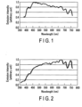
- FIG. 1 shows an example of a light emission spectrum of sunlight in the daytime (12:00 p.m.) in winter (December 16) in Milan, Italy.
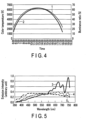
- FIG. 2 shows an example of a light emission spectrum of sunlight in the evening (17:00 p.m.) in spring (May 27) in Tokyo. These light emission spectra were measured by the following method.
- a light detection portion of a colorimetry device (spectral distribution measuring device), in which a diffraction grating is incorporated and has a wavelength component resolving function of light intensity, was directed to the sun. Sunlight was directly taken in the spectral distribution measuring device, and light emission spectra were measured. The wavelength range for measurement was set to 360 nm to 780 nm, which covers the visible light range.
- the adjustment of light intensity that is taken in the spectral distribution measuring device by an exposure time adjustment function which is incorporated in the measuring device, it was confirmed that no saturation phenomenon occurred even in a wavelength region with high light emission intensity.
- light intensity for each wavelength was calculated from electronic data. Based on this result, CIE chromaticity coordinate values, correlated color temperatures and deviations were calculated.
- CIE is the acronym of the Commission Internationale de l'Eclairage.
- Each of the light emission spectra is formed of an irregular curve. If the curves are smoothed, the curves can be approximated to the shape of a blackbody radiation spectrum of an arbitrary color temperature. If the two Figures are compared, since the positions of irregularities in the spectrum curves overlap, it is understood that the irregularities are based not on noise or the like, but on factors inherent to specific floating matter, etc. In particular, portions indicative of characteristic irregularities are present in long wavelength regions, and the degree of irregularities is large. It is thus presumed that the spectrum shape of these wavelength regions is one of factors which cause regional differences or the like. If light emission colors are calculated based on the spectral shapes of FIG. 1 and FIG. 2 , it turned out that the light in FIG. 1 is white light indicative of a correlated color temperature of 5991 K + 0.001 duv, and the light in FIG. 2 is white light indicative of a correlated color temperature of 4483 K - 0.001 duv.
- the white light source of the present invention all light emission colors in the above range can be reproduced.
- the white light source of the present invention includes six kinds of white light sources corresponding to x1, x2, x3, x4, x5 and x6. Specifically, by mixing at least two or more of the six kinds of white light sources with any intensities, all light emission colors in the polygonal range can be reproduced. From FIG. 3
- the range of this shape covers all the light emission colors on the blackbody locus from 2000 K to 6500 K of color temperatures and the white light region with the deviation from the blackbody locus in the range of ⁇ 0.005 duv. Accordingly, in the white light source of the present invention, it is possible to reproduce not merely white light on the blackbody locus, but also subtle deviations of color temperatures which vary due to various environmental factors on the earth.
- the range of color temperatures of white light to be reproduced is 2000 K to 6500 K. By setting these values as the upper and lower limits, color temperatures between two or more kinds of arbitrary light sources can be selected as the range of reproduction.
- each white light source includes all light emission components which can reproduce the light emission spectra of sunlight. Accordingly, when at least two or more kinds of white light sources of the above-described four or more kinds of white light sources are combined, and white light of any color temperature on the blackbody locus or white light of any correlated color temperature close to the blackbody locus is reproduced, the light emission spectral shape of the mixed white light will be similar to the light emission spectral shape of the blackbody radiation of the corresponding color temperatures.
- a light emission spectrum of a white light source of the present invention is characterized by satisfying the following expression (3): ⁇ 0.2 ⁇ _ P ⁇ ⁇ V ⁇ / P ⁇ max 1 ⁇ V ⁇ max 1 ⁇ B ⁇ ⁇ V ⁇ / B ⁇ max 2 ⁇ V ⁇ max 2 ⁇ _ + 0.2
- P( ⁇ ) is the light emission spectrum of mixed white light emitted from the white light source system
- B( ⁇ ) is the light emission spectrum of blackbody radiation having the same color temperature as that of the white light source
- V( ⁇ ) is the spectrum of a spectral luminous efficiency
- ⁇ max1 is the wavelength at which P( ⁇ ) ⁇ V( ⁇ ) is largest
- Xmax2 is the wavelength at which B( ⁇ ) ⁇ V( ⁇ ) is largest.
- the (P( ⁇ ) ⁇ V( ⁇ )) indicates the intensity of the light emission spectrum of the white light source in a spectral luminous efficiency V( ⁇ ) region.
- the (P( ⁇ ) ⁇ V( ⁇ )) is divided by (P( ⁇ max1) ⁇ V( ⁇ max1)) that is the maximum value, whereby the upper limit thereof can be 1.0.
- the (B( ⁇ ) ⁇ V( ⁇ )) indicates the intensity of the light emission spectrum of the blackbody radiation in the spectral luminous efficiency V( ⁇ ) region.
- the (B( ⁇ ) ⁇ V( ⁇ )) is divided by (B(Xmax2) ⁇ V( ⁇ max2)) that is the maximum value, whereby the upper limit thereof can be 1.0.
- the white light source of the present invention satisfies the following expression (4): ⁇ 0.1 ⁇ _ P ⁇ ⁇ V ⁇ / P ⁇ max 1 ⁇ V ⁇ max 1 ⁇ B ⁇ ⁇ V ⁇ / B ⁇ max2 ⁇ V ⁇ max 2 ⁇ _ + 0.1 .
- the white light source system of the present invention at least four kinds of basic white light sources include, without excess or deficiency, the respective light emission color components which sunlight has, and each white light, in which the at least four kinds of light sources are mixed at an arbitrary ratio, also includes the light emission components which sunlight has.
- the white light obtained by the white light source system of the present invention has the characteristics of the blackbody radiation spectrum of each color temperature, and can reproduce fine variations of any wavelength regions.
- one-day variations of sunlight can be expressed as successive variations which are very natural to human eyes.
- David Lewis MacAdam derived from isochromatic experiments of the sense of sight (“Shikisai Kougaku” [Color Engineering], 2nd ed., Tokyo Denki University Press), it was found that if the standard deviation of discernment variations for a central color is expressed on the xy chromaticity diagram, this standard deviation is expressed in a range of a shape called "MacAdam ellipse", and the range of color temperatures which humans can discern is three times the standard deviation.
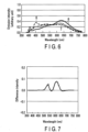
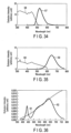
- FIG. 4 is a graph showing a color temperature variation and an illuminance variation of sunlight from 6:00 a.m. to 6:00 p.m. in a day in spring in Tokyo at latitude 35°N.
- a graph denoted by reference sign 1 indicates the color temperature variation
- a graph denoted by reference sign 2 indicates the illuminance variation.
- the graphs were created based on the result of actual measurement for every three minutes of the variation with time of sunlight.
- the illuminance is expressed as an illuminance ratio (%) by relative comparison to a certain value as a reference.
- the one-day color temperature variation of sunlight is a rate of approximately a little less than 200 K per three minutes, the difference in color temperature in every measurement unit in the invention is not perceivable to human eyes. Accordingly, even when the color temperature variation is reproduced by using the measurement data, the moment at which the color temperature of the light source changes cannot be recognized, and the variation can be accepted in a natural manner, as if the color temperature varied continuously.
- the feature of the white light source of the present invention is in the light emission characteristics.
- the white light source may employ any structural member as long as the white light source can reproduce sunlight.
- various light sources are applicable.
- the simplest method is a method of adjusting light emission colors by using phosphors, thus a phosphor-applied product is desirable.
- a light source created by combining an LED (light-emitting diode) with phosphor has excellent features, not only in characteristics but also in manufacture and application, and is optimal.
- an LED having a light emission peak wavelength in a range of an ultraviolet to violet region it is preferable to use, to be more specific, a range of 350 to 420 nm.
- an LED having a light emission peak wavelength in a range exceeding 420 nm is produced, the LED exhibits a sharp light emission at a specific wavelength. Consequently, the balance between this light emission and the light emission of a phosphor having a generally broad spectral shape becomes poorer, and it may be difficult to satisfy the relations of the above expressions (3) and (4).
- the light emission color of the LED is in a range of ultraviolet to violet, since the luminosity function is low, the influence on white light is small.
- the primary light is not emitted from the light emission device by cutting out the primary light from the LED. Therefore, no problem will occur.
- the kind of LED there is no particular limitation, aside from the light emission peak wavelength.
- the LED may be a laser-emission LED, and the material of the LED is not limited.
- a phosphor which is excited by an LED having a light emission peak wavelength of 350 to 420 nm, and exhibits a light emission peak in a range of 420 to 700 nm.
- the peak wavelengths of the respective phosphors deviate by 150 nm or less, or more preferably, by 10 to 100 nm, or still more preferably, by 10 to 50 nm.
- the distance between a certain peak wavelength and a neighboring peak wavelength is 150 nm or less, or more preferably 10 to 100 nm, or still more preferably 10 to 50 nm.
- the light emission spectra of at least two kinds of phosphors constituting the mixture of phosphors satisfy this relationship.
- the half-value width of the light emission spectrum of at least one kind of phosphor constituting the mixture of phosphors is as wide as 50 nm or more, and more preferably 50 to 100 nm.
- phosphors with overlapping light emission spectra it is possible to suppress a variation in light emission color upon long-time continuous lighting.
- phosphors used in the present invention there exists a phosphor having a wide absorption band. Such a phosphor can be not only excited by ultraviolet or violet light, but can also be simultaneously excited by blue light or green light and can emit green light or red light. If a plural of such phosphors with overlapping light emission spectra are used, re-absorption or double excitation tends to more easily occur, which means that it is easier to suppress any variation in light emission color.
- a green phosphor is not only excited by ultraviolet or violet light emitted from the LED and emits green light, but also the green phosphor absorbs light of a blue phosphor which is excited by the LED and emits blue light, and can emit green light.
- the green phosphor can emit light by double excitation by the LED and blue phosphor.
- white light is obtained by mixing, within the device, emission lights of a plural of phosphors such as red, green and blue phosphors. When this white light source is continuously turned on, the brightness of phosphors, in usual cases, gradually decreases with time.
- the chromaticity of the obtained white light is unchanged.
- the luminance degradation rate of a certain kind of phosphor is different from the luminance degradation rates of some other phosphors, excess or deficiency of light emission of a certain component occurs in the obtained white light, and a change occurs in the obtained light emission color.
- the degradation rates are averaged between the phosphors, and it is possible to suppress degradation of only a certain phosphor. As a result, the chromaticity variation of the obtained white light decreases.
- the white light source system of the present invention can reduce the magnitude of the chromaticity variation between the initial time of lighting of the white light source and the time after continuous lighting of 6000 hours to 0.010 or less with use of the CIE chromaticity diagram.
- the magnitude of this chromaticity variation can be decreased to as small as less than 0.010, and, furthermore, to less than 0.009. That the magnitude of chromaticity variation is less than 0.010 refers to the state in which there is no substantial change of color from the initial time of lighting even in the case of long-time use. Thus, sunlight can be reproduced for a long time.
- Concrete phosphors which are usable in the white light source system of the present invention, are as follows.
- the blue phosphor include a europium activated alkaline earth phosphate phosphor (a peak wavelength of 440 to 455 nm), and a europium activated barium magnesium aluminate phosphor (a peak wavelength of 450 to 460 nm).
- examples of the blue-green phosphor include a europium activated strontium aluminate phosphor (a peak wavelength of 480 to 500 nm), and a europium and manganese activated barium magnesium aluminate phosphor (a peak wavelength of 510 to 520 nm).
- Examples of the green phosphor include a europium activated orthosilicate phosphor (a peak wavelength of 520 to 550 nm), a europium activated ⁇ -sialon phosphor (a peak wavelength of 535 to 545 nm), and a europium activated strontium sialon phosphor (a peak wavelength of 520 to 540 nm).
- Examples of the yellow phosphor include a europium activated orthosilicate phosphor (a peak wavelength of 550 to 580 nm), and a cerium activated rare earth aluminum garnet phosphor (a peak wavelength of 550 to 580 nm).
- red phosphor examples include a europium activated strontium sialon phosphor (a peak wavelength of 600 to 630 nm), a europium activated calcium nitridoaluminosilicate phosphor (a peak wavelength of 620 to 660 nm), a europium activated lanthanum oxysulfide phosphor (a peak wavelength of 620 to 630 nm), and a manganese activated magnesium fluorogermanate phosphor (a peak wavelength of 640 to 660 nm) .
- FIG. 34 shows a light emission characteristic of the europium activated orthosilicate phosphor of green light emission, and shows a light emission spectrum 57 having a peak at 527 nm, and an excitation spectrum 58 corresponding to light emission of the peak wavelength 527 nm.
- a long wavelength end of the excitation spectrum 58 of this phosphor spreads to approximately 525 nm, and the phosphor is excited by ultraviolet light, violet light, blue light or blue-green light, and exhibits green light emission.
- FIG. 35 shows a light emission spectrum 59 and an excitation spectrum 60 of the europium activated calcium nitridoaluminosilicate phosphor of red light emission.
- the excitation spectrum 60 of this phosphor spreads from an ultraviolet region to yellow region, and it is understood that the phosphor is excited by ultraviolet light, violet light, blue light or green light, and also by yellow light, and exhibits red light emission.
- a light source of white light emission is constituted by combining the above two kinds of phosphors with a violet LED and a blue phosphor
- the blue phosphor is excited by the LED
- the green phosphor is excited by the LED and blue phosphor
- the red phosphor is excited by the LED
- blue phosphor and green phosphor and re-absorption and multiple excitation occur between the phosphors.
- the luminance variation of blue light also affects the luminance of the green phosphor and red phosphor, and the luminance variation as a whole is averaged. As a result, the suppression effect of chromaticity variation of white light can be obtained.
- Table 1-1 is a list of half-value widths with respect to light emission spectra of phosphors used in the present invention.
- the numerical values in the Table show, as representative values, the half-value widths of light emission spectra corresponding to main peaks, with respect to the light emission spectra of the respective phosphors.
- the half-value widths of most of the phosphors are 50 nm or more. If phosphors to be used are properly selected, it is possible to constitute a white light source in which all phosphors with half-value widths of 50 nm or more are combined.
- a phosphor is mixed with a resin material, and is used in the form of a phosphor film (phosphor layer).
- the periphery of the LED chip is directly or indirectly covered with the phosphor layer. Thereby, primary light, which is emitted from the LED, is converted to secondary light (white light) by the phosphor layer, and the secondary light is radiated to the outside.
- the white light source of the present invention can exhibit a light emission spectral distribution which is substantially equal to the light emission spectral distribution of sunlight. Accordingly, when the white light source of the present invention is used for illumination, high color rendering properties, which are equal to those of sunlight, can be exhibited, and an average color rendering index Ra can be set to 95 or more. Moreover, not only the mean value, but also all of the color rendering indexes R 1 to R 8 and special color rendering indexes R 9 to R 15 can be set to 85 or more.
- the average color rendering index Ra it is possible to set the average color rendering index Ra to 97 or more, and set all of the color rendering indexes R 1 to R 8 and special color rendering indexes R 9 to R 15 to 90 or more.
- the white light source of the present invention when utilized not as illumination for inorganic objects such as works of art, but as illumination for human bodies, it is possible to realize illumination which is kind to human bodies as if it were sunlight.
- LED illumination attention has been paid to the problems of blue light hazards.
- white light is obtained by combining a blue LED with a yellow phosphor or the like, and this is considered to be a factor related to the above hazards.
- a phosphor generally exhibits a broad light emission spectrum, while a blue LED has an excessively sharp spectrum shape having a peak at a specific blue wavelength.
- the light emission spectral distribution of the white light source of the present invention does not have an unnatural spike portion in the blue wavelength region, and the light emission spectrum of sunlight, including the blue wavelength region, can be reproduced. Therefore, the white light source of the present invention can be utilized as an illumination light source kind to human bodies, which does not cause blue light hazards, etc.
- a P( ⁇ )/B( ⁇ ) value which will be described below, is adopted as an index which characterizes the properties of the white light source of the present invention, the P( ⁇ )/B( ⁇ ) value serving as the criterion for satisfying, at the same time, both the color rendering property for the purpose of use as illumination and the safety to human bodies.
- the light emission spectrum of the white light source of the present invention is P( ⁇ )
- the light emission spectrum of blackbody radiation of the corresponding correlated color temperature is B( ⁇ )
- the spectrum of the spectral luminous efficiency is V( ⁇ )
- ⁇ 380 780 P ⁇ V ⁇ d ⁇ ⁇ 380 780 B ⁇ V ⁇ d ⁇
- the light emission spectrum of the white light source of the invention can satisfy, in a wavelength range of 400 nm to 495 nm, a relational expression: P ⁇ / B ⁇ ⁇ _ 1.8 .
- the intensity ratio ((P( ⁇ )/B( ⁇ )) between both in this wavelength region never exceeds 1.8 at maximum.
- a relational expression (5): P ⁇ / B ⁇ ⁇ _ 1.5 can be satisfied in the wavelength range of 400 nm to 495 nm. Accordingly, the white light source of the present invention exhibits a gentler, smoother, continuous spectrum, without an excessive spike of light emission intensity at a specific wavelength in the blue wavelength region.
- the lower limit value of the above-described P( ⁇ )/B( ⁇ ) value is not particularly limited.
- the P( ⁇ )/B( ⁇ ) value indicates a value close to 1.
- the white light source of this invention is a light source which can exhibit fixed values or more of the average color rendering index and special color rendering indexes.
- the white light source of this invention has the feature that approximation is made to the light emission spectrum of blackbody radiation over the entire visible light wavelength range.
- the P( ⁇ )/B( ⁇ ) value of the white light source indicates the ratio of a blue light component which is excessively included, compared to the light emission spectrum of blackbody radiation of the same color temperature. From the standpoint of the degree of influence on human bodies, the upper limit value of the P( ⁇ )/B( ⁇ ) value is particularly important.
- white light emission is obtained by the combination of phosphor light emissions. It is preferable that as much energy of primary light as possible from the LED is absorbed in the phosphor. At the same time, it is necessary to prevent LED light from leaking to the outside of the light source. In particular, when ultraviolet is included in the LED light, it is possible that the body color of a work of art or the like is damaged, or a harmful effect is exerted on the skin or the like of the human body. Thus, the prevention of leakage is strongly required.
- a phosphor layer is formed to have a sufficient film thickness.
- the phosphor layer is formed as a thick film, in order to prevent LED light, which is reflected by the surface of each phosphor particle, from leaking to the outside of the light source through the phosphor layer.
- the thickness of the phosphor layer is too large, the emission light itself of the phosphor cannot exit from the phosphor layer, and the light emission intensity of the phosphor layer lowers. It is generally known that the particle size of a phosphor and the optimal film thickness have a proportional relationship.
- the phosphor layer of this invention a phosphor, whose particles are as large as possible in practical use, is used, and the phosphor layer is formed as thick as possible.
- the phosphor used in the LED module of this invention has an average particle size in a range of 5 ⁇ m to 50 um. A more preferable range of the average particle size is 10 ⁇ m to 40 um. It is preferable that the thickness of the phosphor layer corresponding to this average particle size is in a range of 0.07 mm to 1.5 mm. A more preferable range is 100 ⁇ m to 1000 um.
- the content of the phosphor in the phosphor layer is set such that the mass ratio of the phosphor in the phosphor layer is in a range of 60 mass% to 90 mass%.
- the phosphor content is less than 60 mass%, there is concern that even if the phosphor layer is made thick, the phosphor content in the phosphor layer becomes deficient. If the phosphor content is deficient, part of LED light passes through a gap between phosphor particles and leaks out of the white light source.
- an LED module can be obtained which suppresses leakage of ultraviolet to 0.4 mW/lm or less, and which avoids a reduction in light emission of the phosphor layer to the extent possible.
- an ultraviolet absorption film may be formed on the outside of the phosphor layer.
- an ultraviolet absorption/reflection material use can be made of fine particle white pigments such as zinc oxide, titanium oxide, aluminum oxide, etc. Like the phosphor layer, these fine particle pigments are dispersed in a resin, and an ultraviolet absorption film is formed directly or indirectly on the outside of the phosphor layer.
- the LED module of the objective can be obtained.
- the amount of ultraviolet leaking to the outside of the module can be reduced to 0.4 mW/lm or less.
- UV ⁇ 360 420 P ⁇ d ⁇
- the primary light energy per light flux which is emitted from the light emission device, can be calculated by UV/ ⁇ .
- the white light source of the present invention has substantially the same light emission spectrum shape as that of sunlight, and also has substantially the same intensity level of the light emission spectrum in the wavelength region of blue light as sunlight.
- a leakage prevention film for such light emissions may be formed.
- absorption materials of violet light or blue light fine particle pigments of zirconium oxide or silicon oxide can be used. Like the phosphor layer, these fine particle pigments are dispersed in a resin, and an absorption film is formed directly or indirectly on the outside of the phosphor layer. Thereby, the LED module of the objective can be obtained.
- a measure may be taken by forming an evaporation deposition film of zirconium oxide or silicon oxide on a transparent cover of a white light source, for example, a transparent globe member of an LED bulb.
- FIG. 27 illustrates an example of a white light source system of an embodiment.
- the white light source system of the embodiment includes a white light source unit 21 and a controller 22.
- the white light source unit 21 includes a substrate 23, a plural of white light sources 24 disposed on the substrate 23, and a light emission device cover 25 which is fixed to the substrate 23 in a manner to cover the plural white light sources.
- Each of the white light sources 24 is composed of an LED module.
- the LED module includes an LED chip 26 disposed on the substrate 23, and a phosphor layer 27 which is disposed on the substrate 23 and covers the LED chip 26.
- a wiring network is provided on the substrate 23, and electrodes of the LED chips 26 are electrically connected to the wiring network.
- the light emission device cover 25 may be provided with a lens (not shown) which is disposed on an outer surface of a wall portion facing the substrate 23.
- a lens not shown
- at least a part of the light emission device cover 25 may be formed as a transparent portion which can take out light. It is preferable that the transparent portion is formed in a wall portion on the side opposed to the substrate 23.
- a reflector (not shown) can be disposed, for example, on an inner surface of the light emission device cover 25.
- the controller 22 includes a control unit 28, a memory unit 29, and a data input/output unit 30.
- the white light sources 24, which are composed of the LED modules, are connected to electronic circuit (not shown) of the control unit 28 by wiring lines 31.
- the white light sources 24 emit light by being supplied with electric current flowing from the control unit 28 via the wiring lines 31.
- the electronic circuit memory unit 29 of the control unit 28 one-day variation data of sunlight is stored with respect to each of places and each of seasons (times of year).
- place information such as a city name or latitude/longitude
- time information such as a season
- the control unit 28 extracts stored data corresponding to the input data, reads data of correlated color temperatures and illuminance of sunlight with respect to which the place and season were specified, and calculates, based on these data, the mixture intensity ratio of respective white light sources. Based on the calculation result, the electronic circuit of the control unit 28 controls the value of electric current which is applied to each white light source 24, and can reproduce characteristic variations of required sunlight.
- the LED module including the LED and phosphor is used.
- the LED module includes a substrate, an LED chip disposed on the substrate, and a phosphor layer formed in a manner to cover the periphery of the LED chip.
- a material such as alumina, aluminum nitride, silicon nitride or glass epoxy, is used for the substrate.
- alumina substrate or a glass epoxy substrate it is more preferable to select an alumina substrate or a glass epoxy substrate, judging comprehensively from the standpoints of heat conductivity, resistance to ultraviolet to violet light, insulation, reflectance, cost, etc. It is possible to use one kind or two or more kinds of materials which constitute the substrate.
- any material may be used provided the material emits ultraviolet to violet light.
- a GaN-based material such as InGaN, GaN or AlGaN, can be used.
- a great number of LED chips 52 are arranged linearly on a substrate 51.
- the number of chip lines may be one or more.
- a plural of chip lines can be arranged in accordance with the number of chips that are used.
- a plural of chip lines are arranged in a matrix.
- the LED chips 52 are arranged with a highest possible density.
- the distances between the LED chips 52 are too short, mutual absorption of LED emission light occurs between the LED chips 52, and this is undesirable.
- the arrangement of the chips is not limited to the linear arrangement. Also when the chips are arranged in a staggered fashion or the like, the arrangement with the same high density can be realized.
- the respective LED chips 52 are connected by wires 53, and are connected to electrodes 54.
- the electrodes 54 have a pattern, and serve also as conductors on the substrate 51. It is preferable that at least one kind of metal selected from among Ag, Pt, Ru, Pd, and Al is used as the material of the conductors. It is also preferable that an Au film is formed on the surface of the metal in order to prevent corrosion or the like.
- the Au film may be formed by using any one of a printing method, an evaporation deposition method and a plating method.
- FIG. 29 to FIG. 33 illustrate examples of disposition of the phosphor layer.
- a phosphor layer 55 may be directly formed on the surface of the LED chip 52.
- the periphery of the phosphor layer may be covered with a transparent resin layer 56.
- a substantially entire surface of the transparent resin layer 56 may be covered with the phosphor layer 55.
- a plural of LED chips 52 are covered with a single phosphor layer 55 or transparent resin layer 56.
- a single LED chip 52 may be coated with a single phosphor layer 55 or single transparent resin layer 56.
- such a multilayer structure may be adopted that the periphery of a single or plural LED chips are covered with a transparent resin layer, a phosphor layer is formed on the outside of the transparent resin layer, and an additional transparent resin layer is formed on the outside of the phosphor layer.
- the purpose of forming the transparent resin layer is to average light emission intensities.
- a plural of LED chips are arranged in a certain pattern, both a location where LED chips exist and a location where no LED chip exists are present on the substrate. If the peripheries of the LED chips of such a pattern are covered with a phosphor layer, the light emission intensity is high in the part where the LED chips exist, and the light emission intensity is low in the part where no LED chip exists. Thus, a uniform light emission over the entire surface of the phosphor layer cannot be obtained. At this time, if a transparent resin layer is formed on the inner surface or outer surface of the phosphor layer, it becomes easier to obtain uniform light over the entire layer.
- the reason for this is that if the transparent resin layer is formed on the inner surface of the phosphor layer, primary light from the LEDs is scattered in the transparent resin layer. On the other hand, if the transparent resin layer is formed on the outer surface of the phosphor layer, secondary light from the phosphor is scattered in the transparent resin layer. Aside from the case in which the number of LED chips is plural, even in the case in which the number of LED chips is one, the same advantageous effects can be obtained. Although a general shape of the LED chip is rectangular parallelepipedic, the light emission intensities of light emitted from the respective planes of the rectangular parallelepiped are not equal, and a light intensity distribution occurs depending on directions of emission. Accordingly, if the transparent resin layer is formed on the inner surface or outer surface of the phosphor layer which covers the periphery of the LED chip, the light emission intensity can be averaged, like the case in which the number of LED chips is plural.
- the averaging of light emission intensity is obtained by the light scattering effect in the transparent resin layer.
- a greater scattering effect is exhibited by using, instead of a simple transparent resin layer, a resin layer in which particulate inorganic compound powder is contained.
- the inorganic material powder which is contained in the resin layer, include silica powder such as fumed silica (dry silica) or precipitated silica (wet silica), alumina powder such as fumed alumina or pulverized alumina, and metal oxide powder such as cerium oxide powder, zirconium oxide powder, titanium oxide powder or barium titanate powder.
- silica powder such as fumed silica (dry silica) or precipitated silica (wet silica)
- alumina powder such as fumed alumina or pulverized alumina
- metal oxide powder such as cerium oxide powder, zirconium oxide powder, titanium oxide powder or barium titanate powder.
- One kind or two or more kinds of inorganic materials can be
- the silica powder and alumina powder are preferable as an inorganic compound powder to be contained in the transparent resin layer, since the silica powder and alumina powder are inexpensive and can easily be made into fine particles.
- fumed silica and fumed alumina are suitable since spherical ultra-fine particles can easily be obtained.
- the maximum particle size of the inorganic material powder is 1/4 or less of the wavelength of light passing through the transparent resin layer. If the inorganic compound powder having the maximum particle size of 1/4 or less of the wavelength of light is used, the passing light is properly scattered, the intensity of light emitted from the light source is averaged, and the light distribution can be improved. When the maximum particle size exceeds 1/4 of the wavelength of light, it is highly probable that the light emitted from the LED or phosphor is reflected by fine particles of the inorganic material, and is returned to the inside of the light source (the LED chip side).
- the lower limit value of the maximum particle size of the inorganic material powder is not particularly limited from the aspect of the scattering effect. However, it is difficult to obtain extremely fine particles from the industrial aspect. Besides, from the aspect of handling of powder, the lower limit value of the maximum particle size should preferably be greater than several nm, and more preferably be severalten nm or more.
- a concrete maximum particle size of the inorganic material powder is 140 nm or less for yellow light of 560 nm, and is 105 nm or less for violet light of 420 nm.
- the minimum wavelength of passing light is ultraviolet in a case of using an LED having a light emission peak at 360 nm. If inorganic material powder having the maximum particle size of 90 nm is used, this inorganic material powder is adaptive to transparent resin layers in all cases.
- the above-described inorganic compound powder is contained in the transparent resin layer in a range of 0.1 to 5 mass%. If the content of inorganic compound powder in the transparent resin layer is less than 0.1 mass%, there is concern that the light scattering effect by the inorganic compound powder cannot fully be obtained. On the other hand, if the content of inorganic compound powder in the transparent resin layer exceeds 5 mass%, multiple scattering of light, or the like tends to easily occur, and there is concern that the amount of light extracted to the outside of the light source decreases. It is more preferable that the content of inorganic compound powder in the transparent resin layer is 1 mass% or more.
- the phosphor layer may contain a transparent resin material.
- the transparent resin layer may mainly consist of a transparent resin material, but may contain some other component such as a phosphor or inorganic material powder. Any kind of such transparent resin material may be used if the material has sufficient strength, heat resistance and transparency. Concretely, it is preferable to use silicone resin, epoxy resin, etc. In particular, like the present invention, when the transparent resin layer is used in combination with the LED of ultraviolet emission, it is more preferable to use silicone resin which is excellent in characteristic of resistance to degradation due to ultraviolet.
- the silicone resin is used as the transparent resin material
- the strength of adhesion to the silicone resin-containing layer e.g., silicone resin-containing transparent resin layer and silicone resin-containing phosphor layer
- the adhesion strength between the alumina substrate and silicone resin-containing layer can be set at 1 N (100 gf) or more. It is assumed that the water absorption coefficient of the alumina substrate indicates a value measured by a water absorption coefficient evaluation method disclosed in EMAS-9101.
- the adhesion strength between the alumina substrate and the silicone resin-containing layer indicates a pushing force at a time when the silicone resin-containing layer (phosphor layer) was pushed from the side surface thereof by a tension gauge, and the silicone resin-containing layer (phosphor layer) was peeled.
- the strength of adhesion to the silicone resin-containing layer can be enhanced.
- the water absorption coefficient of the alumina substrate is less than 5%, the permeation of silicone resin is weak, and a sufficient adhesion strength cannot be obtained.
- the silicone resin is excessively permeated, and it becomes difficult to form the silicone resin-containing layer (phosphor layer) in a predetermined shape. It is more preferable that the water absorption coefficient of the alumina substrate is in a range of 20 to 50%.
- the water absorption coefficient of the alumina substrate can be adjusted, for example, by varying the firing temperature at a time of baking the substrate. Concretely, in accordance with the material for forming the alumina substrate, etc., the temperature at a time of baking the substrate is properly adjusted in a range of 1100 to 1500°C. Thereby, the alumina substrate having a proper water absorption coefficient (in a range of 5 to 60%) can be obtained.
- the adhesion strength between the alumina substrate and the silicone resin-containing layer can be set at 1 N or more.
- a transparent silicone resin-containing layer is interposed between the LED chip and phosphor layer, and the adhesion strength between the alumina substrate and the transparent silicone resin-containing layer can be set at 1 N or more.
- the handling efficiency of the LED module is enhanced. Specifically, the peeling of the silicone resin-containing layer at a time of handling is suppressed. Therefore, a failure in lighting or damage due to the peeling of the silicone resin-containing layer can be suppressed, while good reproducibility is obtained.
- phosphors with compositions described in Table 1-2 were mixed at predetermined ratios described in the Table, and white lights of six kinds of color temperatures were obtained.
- Powder with an average particle size of 25 to 35 ⁇ m was used for each phosphor, and a slurry in which the powder was dispersed in a silicone resin was applied to the periphery of an LED chip. Thereby, an LED module was formed.
- the thickness of the phosphor layer was adjusted in a range of 500 to 700 um, and the density of the phosphor powder in the phosphor layer was adjusted in a range of 70 to 80 mass%.
- a GaN-based LED having a light emission peak at 410 nm was used as the LED.
- a reflector, a lens and a cover were attached to this LED module, and electronic circuit was connected to the LED module.
- white light sources of this Example were prepared.
- the reproduced variation is a one-day variation in Yokohama in spring (May 14, 2015).
- the data used for reproduction are data obtained by measuring sunlight emission spectra for about every three minutes from sunrise to sunset in the same day.
- FIG. 5 extracts and shows light emission spectra of sunlight at 7:00 a.m., 12:00 p.m. and 6:45 p.m. in the same day.
- the respective correlated color temperatures were calculated based on the light emission spectrum data.
- the results of calculation were 4236 K + 0.004 duv at 7:00 a.m., 5704 K + 0.001 duv at 12:00 p.m., and 2990 K - 0.004 duv at 6:45 p.m.
- the sunlight emission spectra at the three time instants were reproduced by using the above six kinds of white light sources (white light sources 1 to 6) of the present invention.
- the mixture ratios of the respective light source colors are as shown in Table 2.
- the numerals in the Table indicate intensity ratios (relative values).
- light emission spectral distributions of three kinds of white light sources are as shown by curves 6 to 8 in FIG. 6 . If these light emission spectrum shapes are compared with light emission spectra of blackbody radiation of the same color temperature, it is understood that the overall shapes of both show good agreement, aside from microscopic irregularities appearing in the light emission spectrum curves. In particular, in the wavelength range of 400 nm to 650 nm to which human eyes have high sensitivity, both showed very similar curves.
- difference spectra between both were calculated.
- the difference spectrum is obtained as follows.
- P( ⁇ ) is the light emission spectrum of each white light source
- B( ⁇ ) is the light emission spectrum of blackbody radiation having the same color temperature as the white light source
- V( ⁇ ) is the spectrum of a spectral luminous efficiency
- ⁇ max1 is the wavelength at which P( ⁇ ) ⁇ V( ⁇ ) becomes largest
- ⁇ max2 is the wavelength at which B( ⁇ ) ⁇ V( ⁇ ) becomes largest
- P ⁇ ⁇ V ⁇ / P ⁇ max 1 ⁇ V ⁇ max 1 ⁇ B ⁇ ⁇ V ⁇ / B ⁇ max 2 ⁇ V ⁇ max 2 is calculated.
- the difference spectrum is obtained by plotting the calculated value over the visible light wavelength range of 380 nm to 780 nm. As is understood from FIG. 7 to FIG. 9 , with respect to each of the light sources A, B and C, the difference spectrum is in the range of ⁇ 0.1 or less, and satisfies the above expression (3). Thus, each of the light sources has characteristics suitable for the white light source of the present invention.
- the color rendering indexes of these light sources were calculated.
- the data of each spectrum intensity was calculated at intervals of 5 nm over the wavelength range of 380 nm to 780 nm.
- calculations were made according to the method described in JIS-8726, and the average color rendering index and special color rendering indexes were calculated.
- Table 3 The results are shown in Table 3 below.
- the white light sources of Example 1 indicate high values in all evaluation indices, and exhibit excellent color rendering properties which are substantially equal to those of sunlight.
- Each of the white light sources of Example 1 employs the LED module in which the violet emission LED having the light emission peak at 410 nm and the four kinds of phosphors are combined.
- the LED has a light emission spectrum having a sharp shape at a light emission peak wavelength, and the phosphor has a broad light emission spectrum.
- the whole spectrum shape tends to become unnatural, with a spike of light emission of the LED.
- the light emission peak of the LED used in Example 1 exists not in the blue region but in the violet region. Blue light is not conspicuous, and most of violet light emitted from the LED is absorbed by the phosphor.
- the white light source of the present invention can be configured as a white light source which is kind to human bodies, with no fear of blue light hazards, etc.
- the value of P( ⁇ )/B( ⁇ ) of each white light source was obtained by calculation.
- the calculation method of the P( ⁇ )/B( ⁇ ) value is as follows. To begin with, the light emission spectral distribution of the light source C is measured by using a spectral distribution measuring device. Various kinds of devices have recently been commercially available as the spectral distribution measuring device. If there is no problem with precision, the type of device does not need to be particularly restricted. A concrete shape of the light emission spectrum is as shown by the curve 8 in FIG. 6 , as already described, and this emission spectrum is set as P( ⁇ ).
- the P( ⁇ )/B( ⁇ ) value can be calculated.
- the result will vary in any way, depending on the method of calculation.
- the P( ⁇ ) and B( ⁇ ) which satisfy this condition were calculated, and then both were compared.
- V( ⁇ ) is the spectral distribution of the spectral luminous efficiency
- each spectral distribution of the P( ⁇ ) and B( ⁇ ) which satisfy the above equation (1) was obtained by calculation. If the P( ⁇ ) and B( ⁇ ) after correction are shown together in one graph, spectral distributions shown in FIG. 10 are obtained.
- a curve 9 is B( ⁇ ) after correction, and a curve 10 is P( ⁇ ) after correction.
- the maximum value of the P( ⁇ )/B( ⁇ ) ratio as calculated in the above is adopted as a representative value, and is set as an evaluation reference of each white light source. Specifically, if the P( ⁇ )/B( ⁇ ) value exceeds 1 and indicates a greater value, this means that an excessive and large amount of visible light of 400 nm to 495 nm included in each white light source, in particular, blue light, is included relative to the visible light of the same wavelength range included in the light emission spectrum of the blackbody. From the above, it is understood that the light source C satisfies the relationship of the following expression (9) in the wavelength range of 400 nm to 495 nm: P ⁇ / B ⁇ ⁇ _ 1.37
- the white light sources C, B and A are regarded as light sources which exhibit smooth light emission spectra with less irregularities in the blue wavelength region, and scarcely exert a harmful effect on the circadian rhythms of human bodies.
- the amount of ultraviolet leaking from the module is reduced.
- the LED primary lights leaking from the light sources of the Example were calculated by using the above equations (7) and (8), the LED primary lights were all 0.1 mW/lm, and were very weak. Accordingly, when the white light sources of Example 1 were used as illumination for works of art or the like, the pigments or the like used in the works of art were not deteriorated. When the white light sources of Example 1 were used as illumination for human bodies, the skin or eyes of human bodies were not damaged, and suitable illumination for these purposes was successfully obtained.
- FIG. 13 is a graph showing one-day variations in Yokohama in spring (May 14, 2015).
- the values of respective correlated color temperatures were calculated, and sunlight was reproduced by determining the mixture ratio of the light source 1 to light source 6 such that predetermined correlated color temperatures can be obtained.
- the variation of illuminance was plotted as an illuminance ratio (%), by calculating relative values with reference to a certain value.
- a curve 15 indicates the variation of the correlated color temperature
- a curve 16 indicates an illuminance variation.
- the one-day variation in Yokohama in spring was such that the illuminance became brighter with the sunrise, the illuminance took a maximum value at around 11:00 a.m. and then remained high until after 1:00 p.m., and the illuminance gradually decreased toward sunset.
- the color temperature the sun in crimson of about 2200 K appeared at sunrise, the color temperature increased in accordance with the increase of illuminance, warm white changed to white and to daylight white, and the color temperature reached about 6000 K at maximum at around 12:00 p.m. Thereafter, with the progress reverse to the morning, the color temperature decreases back to 2300 K at around 7:00 p.m., and then the sun set.
- the variations with time of the color temperature and illuminance shown in FIG. 13 were reproduced by controlling the values of electric currents applied to the white light sources.
- the intensity ratio of electric currents applied to the light source 1 to light source 6 was determined.
- the intensity of the total electric current was adjusted such that a predetermined illumination can be obtained while the above-described current ratio is maintained.
- the program control of current values is executed such that the data of the variation with time shown in FIG. 13 can be adjusted based on the actual measurement values every three minutes, and the variation with time of the sunlight was reproduced.
- This white light source system was applied as illumination for an art museum, a hospital, and a home.
- instantaneous characteristics of sunlight are not reproduced, but light emission characteristics, which vary from time to time, are reproduced. Good influence on the circadian rhythms which human bodies have can be expected.
- characteristic variation of white illumination gentle variations, which are not perceptible to human eyes, are reproduced. Thus, such variations are perceived by humans as very natural variations like sunlight. Accordingly, even inpatients or the like, who are physically weak, can accept the reproduced light as natural illumination.
- a LED module which was used, is a combination of a blue LED and a yellow phosphor.
- a europium activated orthosilicate phosphor having a peak wavelength at 560 nm was used for the phosphor.
- the average particle size of the phosphor was 7 ⁇ m.
- a phosphor slurry was created by dispersing the phosphor particles in a silicone resin. The slurry was uniformly applied in a manner to cover the LED chip disposed on the substrate. Thereby, the LED module was formed.
- the film thickness of the phosphor layer was about 65 ⁇ m, as a result of adjustment to such a thickness that desired white light is obtained by mixing blue light of the LED and yellow light of the phosphor.
- a reflector, a lens and a cover were attached to this LED module, and electronic circuit was connected to the LED module.
- a white light source of this Comparative Example was fabricated.
- the color temperature of the obtained white light source was 6338 K, and the light emission spectrum characteristic, (P( ⁇ ) ⁇ V( ⁇ )/(P( ⁇ max1) ⁇ V( ⁇ max1)), was as shown in FIG. 14 .
- the blackbody radiation spectrum of the corresponding color temperature of 6338 K if B( ⁇ ) ⁇ V( ⁇ )/(B( ⁇ max2) ⁇ V(Xmax2)) is calculated, a curve shown in FIG. 15 was obtained. Furthermore, a difference spectrum between FIG. 14 and FIG.
- the white light source of Comparative Example 1 agreed with the color temperature on the locus of blackbody radiation. However, since the light emission spectrum shape was different, such high color rendering properties as sunlight could not be exhibited.
- the average color rendering index Ra was as low as about 70, and R 1 to R 15 were as shown in the Table below, which were very different from the characteristics of sunlight.
- the characteristics of the blue wavelength region were confirmed.
- the light emission spectrum of the white light source of Comparative Example 1 is P( ⁇ )
- the light emission spectrum distribution of blackbody radiation having the corresponding correlated color temperature is B( ⁇ )
- the spectrum of the spectral luminous efficiency is V( ⁇ )
- ⁇ 380 780 P ⁇ V ⁇ d ⁇ ⁇ 380 780 B ⁇ V ⁇ d ⁇
- the light emission spectrum of the white light source of Comparative Example 1 exhibited a relationship of the following expression (12) in a wavelength range of 400 nm to 495 nm: P ⁇ / B ⁇ ⁇ _ 1.87 and the P( ⁇ )/B( ⁇ ) value exceeded the upper limit value of 1.8 of the white light source of the present invention.
- the white light source of Comparative Example 1 has a sharp light emission spectrum shape having a peak in the neighborhood of 450 nm. Compared to the light emission spectrum shape of blackbody radiation, this spectrum shape has an excessive projection portion near 450 nm and has an excessive recess portion before 500 nm, and this light emission spectrum had clearly different characteristics from the blackbody radiation (sunlight). In the meantime, the white light source using the blue LED is characterized by such a conspicuous projection portion. As the color temperature of the white light source becomes lower, this projection portion becomes more conspicuous. Accordingly, although the white light source of Comparative Example 1 was the white light source of the color temperature which is as high as 6338 K, there is a tendency that if the color temperature becomes lower, the P( ⁇ )/B( ⁇ ) value becomes greater than 1.87.
- the white color source of Comparative Example 1 apparently exhibited the same white light emission as the present invention, but exhibited characteristics which are poor in redness and have a low color rendering property.
- a white light source is used as illumination for a hospital, since a strong light emission wavelength component is included in the blue region, there is concern about the problem of blue light hazards, etc., and the harmful effect on circadian rhythms of human bodies.
- the white light source of Comparative Example 1 since the blue light emission LED was used as the LED module, little ultraviolet is included in the white light source of Comparative Example 1. However, if an ultraviolet light emission LED is used, it is clear that a great amount of ultraviolet leaks.
- the ultraviolet light emission LED is used as illumination for an art museum, there is concern about harmful effects as a matter of course, such as increased fading of paintings.
- the white light source of Comparative Example 1 are too greatly different from those of sunlight in every aspect, it is meaningless to reproduce one-day sunlight variations by using the white light source of Comparative Example 1.
- a white light source system which uses such a white light source, was not created.
- Evaluation experiments were conducted as to how the blue light emission component included in the white light source of the present invention is perceived by human bodies.
- the P( ⁇ )/B( ⁇ ) value shown in the above equation (1) is used as a criterion of evaluation. If this numerical value is as close as possible to 1, this value is a most desirable value, judging comprehensively from the aspects of the color rendering property of the illumination light source and the safety to human bodies. On the other hand, from the aspect of safety, it is preferable that this numerical value is as small as possible. Confirmation experiments were conducted as to what values are tolerable as the upper limit value.
- the physical characteristics of blue light are utilized as a method for evaluating the degree of influence of blue light upon eyes, by distinguishing this degree of influence from the degree of influence of other visible light.
- the light emission component of the wavelength range of 400 to 495 nm including blue light has higher energy than the visible light components of other wavelengths.
- electromagnetic waves having high energy tend to collide with various obstacles while traveling through space and tend to be easily scattered.
- blue light is scattered more easily than other visible light components.
- a blue light emission component is scattered by the influence of floating matter such as gas molecules and dust in the air, and, at the same time, the blue light reaching the inside of the eye strongly undergoes the influence of scattering while traveling through the crystal lens.
- vision cells of the retina which the blue light reaches after passing through the crystal lens, are composed of cones, which are mainly located in a central part of the retina and which normally perceive a bright image, and rods, which are mainly located in a peripheral part of the retina and which perceive a dark image.
- scattered blue light reaches rods which normally sense a dark image. If bright scattered light that is not normally sensed by the rods reach the rods, the sphincter muscle of the pupil excessively contracts, and a human strongly senses dazzle.
- the mechanism of sensing dazzle differs between both cases. Accordingly, by utilizing this phenomenon, for example, the overall intensity of the white light source is kept constant, and then the content ratio of the blue light component that is a constituent of the white light is varied. Thereby, the degree of dazzle perceived by humans can correctly be evaluated. Specifically, even when the amount of light reaching the cones is constant or slightly decreases, if the amount of light reaching the rods increases, humans sense dazzle more strongly. To measure this variation is the most effective means for evaluating the influence of blue light upon the human body.
- a white light source was fabricated in which the light emission intensity of the blue wavelength region in the light emission spectrum of white light was reduced as much as possible.
- an ultraviolet to blue light absorption film was formed on the LED module of the light source B of Example 1.
- a three-layer film was formed on the periphery of the phosphor layer which covers the periphery of the LED chip of the light source B of Example 1.
- Each of the thin films was formed such that fine particle powder was dispersed in a silicone resin, the specific gravity and viscosity were adjusted, and then a predetermined amount of a slurry of the result was applied.
- a predetermined electric current was applied to the obtained LED module, and it was confirmed that the LED module emits white light.
- the light emission spectral distribution of white light emitted from the LED module was measured by using the spectral distribution measuring device. Based on the obtained light emission spectrum data, a chromaticity point on the (x, y) chromaticity diagram was calculated. The calculated chromaticity point was 5110 K - 0.002 duv. It turned out that the color temperature shifted to a lower color temperature side by about 600 K, relative to the correlated color temperature of 5704 K + 0.001 duv of the light source B before the violet to blue component was cut.
- the light emission intensity of the obtained white light source was compared with the light emission intensity of blackbody radiation, the light emission intensity of the light source of Example 2 never exceeded the light emission intensity of blackbody radiation in the entire wavelength range of 400 nm to 495 nm.
- Example 2 four kinds of white light sources (4) to (7) of Example 2, which exhibit relatively large values of the above P( ⁇ )/B( ⁇ ) value, were fabricated. All the materials and parts used in the fabrication are the same as those in Example 1, and the parts were assembled in the same manner as in Example 1. Specifically, the light source colors of the white light sources 1 to 6 of Example 1 were mixed at mixture ratios shown in Table 5-2. Thereby, the four kinds of white light sources (4) to (7) of Example 2 were obtained.
- the numerals in Table 5-2 indicate intensity ratios (relative values). The intensity ratios were controlled by controlling the values of electric currents which are applied to the white color sources 1 to 6.
- the light emission spectra of the additionally experimentally fabricated white light sources (5) to (7) were compared with the light emission spectra of blackbody radiation corresponding to the white light sources. Then, graphs of FIG. 18 , FIG. 19 and FIG. 20 were obtained.
- the maximum values of the P( ⁇ )/B( ⁇ ) value in the wavelength range of 400 nm to 495 nm were 1.47 in the light source of FIG. 18 , 1.69 in the light source of FIG. 19 , and 1.76 in the light source of FIG. 20 .
- the difference spectra of the white light sources (4) to (7) were in the range of ⁇ 0.1 or less, and satisfied the above expression (3).
- Light source 1 Light source 2
- Light source 3 Light source 4
- Light source 5 Light source 6
- Light source (4) 0. 09 - 0. 51 0. 34 - 0. 06
- Light source (5) 0. 09 - 0. 70 0. 18 - 0. 03
- Light source (7) - 0. 14 0. 43 0. 33 0. 10 -
- the amount of the phosphor combined with the LED was changed by decreasing the thickness of the phosphor layer to 55 ⁇ m, and the white light source exhibiting a different P( ⁇ )/B( ⁇ ) value was fabricated.
- a concrete light emission spectrum shape is as shown in FIG. 36 , and the maximum value of the P( ⁇ )/B( ⁇ ) value in the wavelength range of 400 nm to 495 nm was 3.28.
- the ten kinds of light sources of the above Table 5-1 were prepared.
- the ten kinds of light sources were successively lighted under the operational condition under which the luminances of the light sources become equal.
- the curtains of windows were closed, and the brightness of ceiling illumination was constantly kept at a fixed value so that the indoor illuminance may not change.
- a human stands at a position at a distance of 3 m from the light sources. The human directly viewed each light source, and the strength of a stimulus received from the light source was comparatively evaluated.
- the ratio of persons who sensed dazzle of the light source (4) is 14%, while this ratio is 28% with respect to the light source (5), and a large difference was recognized. If the P( ⁇ )/B( ⁇ ) values of both are confirmed, this value is 0.98 in the light source (4), while the value is 1.47 in the light source (5). In accordance with the magnitude of the P( ⁇ )/B( ⁇ ) value, the ratio of scattering light incident on the eyes increased, thus influencing the degree of perception of dazzle.
- the P( ⁇ )/B( ⁇ ) value defines the amount of blue light which is excessively included, compared to the corresponding blackbody radiation.
- the color temperature of blackbody radiation which is a reference for comparison, is 2990 K in the light source (3), while this color temperature is 5704 K in the light source (2).
- the blue light component of the light source (2) was greater than the blue light component of the light source (3).
- the content of the blue light component in the white light source influences the degree of perception of dazzle by humans, and that as the P( ⁇ )/B( ⁇ ) value becomes greater, more dazzle is perceived by humans.
- This result is the content that supports the initial assumption, and the influence by the excess blue light emission component is considered to be particularly important as the factor by which the white light source was perceived as dazzling.
- the P( ⁇ )/B( ⁇ ) values are 1.87, 2.11 and 3.28, which exceed 1.8 and are large values. The level of these values is such that more than half the test subjects sensed dazzle of blue light.
- the light source with which dazzle is so strongly sensed, is an illumination for which there is concern about problems of blue light hazards or the like, which have attracted attention in recent years. In connection with this light source, the investigation of the truth and the study for improvements are to be expected in the future.
- the P( ⁇ )/B( ⁇ ) values are in the range of 0.98 to 1.76, and an improvement has been made so as to make the blue component smaller than in the conventional light sources of the Comparative Example.
- the ratio of persons sensing dazzle is less than 50%, and it is judged that the light of the white light sources of the Example has been improved with respect to the problems of blue light hazards or the like.
- the color temperatures are 2990 K to 5704 K and the P( ⁇ )/B( ⁇ ) values are in the range of 0.98 to 1.76.
- the white light sources of the present invention are characterized in that the color temperatures are in the range of 2000 K to 6500 K, and the P( ⁇ )/B( ⁇ ) values are in the range of 1.8 or less. Accordingly, the content of the blue light component in the white light source of the present invention is less than that in the white light source of Comparative Example 1 which is the conventional light source. This is because the color temperature of the white light source of Comparative Example 1 is 6338 K and is substantially close to the upper limit value.
- the color temperature of the white light source of the present invention is substantially equal to or less than the color temperature in Comparative Example 1, the content of the blue light component is equal to or less than that in Comparative Example 1. Besides, since the P( ⁇ )/B( ⁇ ) value is less than in Comparative Example 1, the content of the blue light component in the white light source of the present invention is surely less than that in the white light source of Comparative Example 1.
- the white light source e.g., white light source V of this invention in which the P( ⁇ )/B( ⁇ ) value is 1.5 or less
- the ratio of persons sensing dazzle is substantially halved, compared to the ratio with respect to the light source of Comparative Example 1, and the influence of the blue light component can be reduced more conspicuously.
- the white light source of the present invention has obvious effects of improvement, compared to the conventional light source that is the Comparative Example.
- a white light source system which is composed of four kinds of white light sources, was fabricated.
- the number of white light sources, which constitute the system is limited to a minimum necessary number.
- the range, in which the spectrum of blackbody radiation can be accurately reproduced becomes narrow.
- this system is a white light source system including light sources 7 to 10 shown in FIG. 37 .
- a white light source system including light sources 7 to 10 shown in FIG. 37 .
- a white light source system including light sources 7 to 10 shown in FIG. 37 .
- a white light source system including light sources 7 to 10 shown in FIG. 37 .
- a white light source system including light sources 7 to 10 shown in FIG. 37 .
- a white light source system including light sources 7 to 10 shown in FIG. 37 .
- a white light source system including light sources 7 to 10 shown in FIG. 37 .
- a white light source system including light sources 7 to 10 shown in FIG. 37 .
- correlated color temperatures within a deviation of ⁇ 0.005 duv can be reproduce
- the four kinds of white light sources were fabricated in the following procedure. As illustrated in FIG. 38 , on an alumina substrate 71 having an outside shape of 30 ⁇ 30 mm, LED chips 72 each having a chip shape of 0.4 ⁇ 0.4 mm were disposed in a 5 (in series) ⁇ 5 (in parallel) matrix. For the LED, GaN of violet light emission having a light emission peak wavelength at 405 nm was used. In addition, in the LED module 70 shown in FIG.
- each of chip columns, in which the LED chips 72 are connected in series, is independently covered with a transparent resin layer (not shown), and the entire surface of each of the transparent resin layers of the plural columns is covered with a phosphor layer 73.
- fumed silica with an average primary particle size of 7 nm and a maximum particle size of 25 nm was added as fine particle silica powder in an amount of 3 mass% relative to the transparent resin.
- phosphor powder as each phosphor powder which is contained in the phosphor layer, phosphor powder with an average particle size of 30 to 40 ⁇ m was used.
- the transparent resin layer was formed by applying a slurry, in which fine particle silica powder is dispersed in silicone resin, to the periphery of the LED chip.
- the phosphor layer 73 was formed by applying a slurry, in which phosphor powder is dispersed in silicone resin, to the entire surface of the transparent resin layer.
- the thickness of the phosphor layer 73 was set at 500 to 750 ⁇ m, and the density of phosphor powder in the phosphor layer was adjusted to fall within the range of 75 to 85 mass%.
- a conductor 75 is formed as an electrode on the substrate 71, and each LED chip 72 is connected to the electrode.
- the material of the electrode Pa metal was used.
- an Au film was formed on the surface of the electrode by a printing method.
- a dam 74 is disposed in a manner to surround the columns of LED chips 72 on the substrate 71.
- a reflector, a lens and a cover were attached to this LED module 70, and electronic circuit was connected to the LED module 70.
- white light sources included in the white light source system of Example A were fabricated.
- Each white light source is a combination of four kinds of phosphors, namely a blue phosphor, a green phosphor, a yellow phosphor and a red phosphor, and an LED.
- the kinds and mixture ratios of the respective phosphors, and the correlated color temperatures of the obtained light sources are as shown in Table 8 below.
- FIG. 39 to FIG. 42 show graphs in which light emission spectra of the four kinds of white light sources are compared to the spectra of blackbody radiation of the corresponding color temperatures.
- the spectra of the four kinds of light sources agree with the spectra of blackbody radiation to a high extent. Difference spectra between the respective white light sources and the corresponding blackbody radiation spectra were calculated. In all of the four kinds, the difference spectra are in the range of ⁇ 0.2 or less, and it was confirmed that the relational expression (3) is satisfied. Accordingly, each of the light sources has characteristics suitable for the white light source of the present invention, and white light obtained by mixing white lights of the four kinds is also suitable for the white light source of the present invention, and can reproduce sunlight.
- the P( ⁇ )/B( ⁇ ) values obtained by the above relational expressions (2) and (5) were confirmed.
- a light source 11 was obtained.
- the correlated color temperature of the mixed white light source was 6000 K + 0.001 duv. If the spectrum shape is compared with the spectrum of blackbody radiation of the same color temperature, the comparison result is as shown in FIG. 44 .
- the P( ⁇ )/B( ⁇ ) value is 1.17, and it was confirmed that the light source satisfies each of the relational expression (2) and relational expression (5).
- the light emission spectra of the white light sources of the present invention can exhibit continuous spectra without a break over the wavelength range of 380 nm to 780 nm.
- the continuous spectrum means a spectrum which does not include, in this wavelength range, a planar wavelength region where the light emission intensity is substantially zero.
- the light emission spectrum of FIG. 39 of the light source of the present invention is compared with the light emission spectrum shape of FIG. 17 of the light source of Comparative Example 1, which was fabricated in Example 1.
- One to three recess portions are observed in the curves of both spectra. Such a recess portion occurred due to a gap between neighboring two kinds of light emission spectra.
- the reason why the light emission intensity at the bottom of the recess portion does not become zero is that a long wavelength end of a short wavelength-side light emission spectrum and a short wavelength end of a long wavelength-side light emission spectrum overlap.
- the reason why the degree of irregularity of the spectrum curve is less in the light source of the present invention than in the light source of the Comparative Example is that the area of overlap between light emission spectra is large. This effect occurs by making as close as possible the light emission spectra with large half-value widths.
- the kinds of phosphors in such a combination By further selecting the kinds of phosphors in such a combination, re-absorption between phosphors becomes easier to occur, and also double excitation or the like becomes easier to occur.
- the light emission color variation during continuous lighting of the light source can be suppressed as low as possible.
- the smooth curve with less irregularity can be obtained, it is natural that the light emission spectrum of blackbody radiation can easily be reproduced and the color rendering property or the like can be improved.
- the light sources of the present invention are characterized in that the light emission intensity does not become zero even in a near-ultraviolet region of 380 nm or a deep red region of 780 nm.
- planar curves appear in a region of 400 nm or less and in a region of 750 nm or more, and the level of the intensity thereof can be regarded as substantially zero.
- the white light source of the present invention over the entire wavelength region of 380 nm to 780 nm which is the object of evaluation of the color rendering evaluation index, there is no planar wavelength region in which the light emission intensity is substantially zero.
- the white light source of the present invention can exhibit high numerical values, not only with respect to the average index Ra, but also with respect to R 1 to R 15 .
- Concrete values are as shown in Table 9.
- FIG. 18 to FIG. 20 show other examples of continuous spectra with no break over the entire wavelength range of 380 nm to 780 nm, that is, light emission spectra including no planar wavelength region in which the emission intensity is substantially zero.
- the white light source 12 is a light source of the Comparative Example, which was experimentally fabricated for the purpose of comparison of characteristics.
- the basic configuration of the LED module is the same as that of the light sources 7 to 10 of Example A.
- InGaN having a light emission peak at 455 nm was used for the LED, and a cerium activated yttrium aluminum garnet phosphor was used as a phosphor to be combined.
- the thickness of the phosphor layer and the amount of phosphor were adjusted such that white light of a color temperature of 5300 K is emitted from the light source 12 of the Comparative Example. Concretely, the film thickness was set at 0.15 mm, and the content of phosphor powder in the phosphor layer was set at 10 mass%.
- the chromaticity variation after continuous lighting exceeded 0.01 and was large.
- the white light of the light source 12 is obtained by the mixing the blue light of the LED and the yellow light of the phosphor, the speed of the decrease in luminance of the LED and the speed of the decrease in luminance of the phosphor during continuous lighting are different, and thus such a large variation was exhibited.
- the white light sources 7 to 11 of the present invention all the constituent components of the white light utilize the emission lights of phosphors, and the phosphors used are doubly excited by the LED and phosphors. Moreover, the combination in which re-absorption between the phosphors occurs is adopted.
- the speeds of the decrease of luminance in the respective phosphors are averaged.
- the effect of reduction of the color variation was brought about.
- the magnitude of the chromaticity variation in each light source was 0.01 or less, and was small.
- White light sources were fabricated in order to examine the relationship between the water absorption coefficient of the alumina substrate and the adhesion strength of the silicone resin. Except for the material of the substrate, use was made of the same members for fabricating the light sources as those of the light source 7 of Example A.
- the basic configuration of the LED module was also the same as that of the light source 7. However, in order to evaluate the strength of the resin film, the configuration was simplified, and a linear arrangement of only one column was adopted as the chip arrangement of LEDs, instead of the matrix-type arrangement.
- an alumina substrate (shape: 8 ⁇ 3 ⁇ 0.38 mm) with a water absorption coefficient of 5.8% was prepared.
- the temperature at a time of baking this alumina substrate was set at 1480°C, and thereby the water absorption coefficient was adjusted to 5.8%.
- Three LED chips were linearly arranged on this substrate, and were connected in series.
- a slurry including four kinds of phosphors and silicone resin was applied onto these LED chips such that the three LED chips were covered at the same time, and the silicone resin was cured by a heat treatment at a temperature of 140°C. In this manner, a columnar phosphor layer was formed with a size of 6.5 mm in longitudinal dimension, 2.5 mm in transverse dimension, and 1.9 mm in thickness.
- alumina substrates having water absorption coefficients of 38% and 59%, respectively, were prepared, and the same LED modules as in the light source 13 were fabricated.
- an LED module having a double-layer structure of a transparent silicone resin layer and a phosphor layer was fabricated.
- Three LED chips were mounted on an alumina substrate having a water absorption coefficient of 11%.
- a silicone resin including no phosphor was applied.
- a phosphor slurry prepared for the light source 13 was applied.
- the resultant was subjected to heat treatment at a temperature of 140°C, and the silicone resin was cured. Thereby, a double-layer film was formed in which the thickness of the transparent silicone resin layer is 3 mm and the thickness of the phosphor layer is 0.5 mm.
- a module to be described below was fabricated.
- the module was fabricated by the same method as the light source 13, except that an alumina substrate having a water absorption coefficient of 0% was used as the substrate material.
- An electric current of 20 mA was passed through the above five kinds of white light sources 13 to 17 and the light source 10 of Example A, and the light emission efficiency of each light source was measured. Thereafter, the adhesion strength between the silicone resin and substrate was measured by a predetermined method. The result is shown in Table 11.
- the adhesion strength between the silicone resin layer and substrate indicated a characteristic of more than 1 N, and light sources with no peeling of the resin layer and with good handling efficiency were successfully obtained.
- White light sources were fabricated for confirming the characteristic effect of the transparent resin layer that is a constituent member of an LED module, and characteristic effect of inorganic fine particle powder included in the transparent resin layer.
- the members used for fabricating the light sources were exactly the same as those in the light source 7 of Example A.
- unique configurations were adopted for the purpose of evaluation.
- alumina substrate 8.0 mm in longitudinal dimension ⁇ 3.0 mm in transverse dimension
- solder paste or the like at intervals of 2.0 mm.
- the bonded LED chips were wire-bonded to the wiring pattern by using gold wires.
- the LEDs and gold wires were coated with a thermosetting transparent silicone resin.
- a necessary amount of the resin was applied by using a dispenser, a mask or the like, such that the center LED chip is set at the center, and the three LEDs are coated with a common continuous transparent resin layer.
- the resin was heated and cured at temperatures of 100 to 150°C, and thus the transparent resin layer was formed.
- the size of the transparent resin layer was 5.5 mm in longitudinal dimension ⁇ 2.5 mm in transverse dimension, and the thickness thereof was 1.2 mm.
- a silicone resin including a phosphor was applied to the surface of the transparent resin layer, and heated and cured. Thereby, a phosphor layer (7.5 mm in longitudinal dimension ⁇ 3.0 mm in transverse dimension ⁇ 1.5 mm in thickness) was formed, and the LED module of Example C was fabricated.
- a light source 19 a light source having exactly the same configuration as the light source 18, except for the transparent resin layer, was fabricated.
- the transparent resin layer the three LED chips were not coated with the continuous transparent resin layer. Instead, each of the LED chips was coated with an individual independent transparent resin layer.
- the phosphor layer the three transparent resin films were coated with an identical continuous phosphor layer, and the same phosphor layer (7.5 mm in longitudinal dimension ⁇ 3.0 mm in transverse dimension ⁇ 1.5 mm in thickness) as in the light source 18 was formed.
- a light source 20 was fabricated.
- the light source 20 was formed with the same configuration as the light source 18 and light source 19. However, the transparent resin layer was not formed between the LED and the phosphor layer.
- the above three kinds of light sources and the light source 10 of Example A were evaluated in the following procedure.
- nine measurement points A to I on a phosphor layer 84 were determined, and the luminances on the respective measurement points were measured by a two-dimensional color/luminance analyzer CA-2000 (manufactured by KONICA MINOLTA JAPAN, INC.). From the measured values of the luminance at the respective measurement points, the nonuniformity in luminance of each semiconductor light emission device was evaluated. The result is as shown in Table 12. Numerical values in the Table are luminance (Cd/m 2 ), and numerical values in parentheses () are relative values in the case in which the luminance at point E was set as 100.
- the kinds of inorganic fine particle powder dispersed in transparent resin layers were evaluated.
- the evaluation was conducted by fabricating light sources in which various kinds of inorganic fine particle powder were disposed in transparent resin layers, and by measuring the light emission efficiencies of the obtained light sources.
- the light emission efficiencies were measured by using an integrating sphere manufactured by Labsphere, Inc.
- the device configuration of the LEDs was identical to that of the light source 18 of Example C, except for the presence/absence of inorganic fine particle powder in the transparent resin layer.
- Table 13 also shows the result relating to the light source 10 of Example A.
- the light emission efficiency is excellent in the light source 10 of Example A and light sources 21 to 23 of Example D which use inorganic fine particle powder with a maximum particle size of 1/4 or less of the light emission peak wavelength (405 nm) of the LED chip, compared to the light sources 24 and 25 of Example D which use inorganic fine particle powder with a maximum particle size of more than 1/4 of the light emission peak wavelength (405 nm) of the LED chip.
- the light source 10 and light source 21, which use fumed silica with a maximum particle size of 25 ⁇ m exhibited excellent characteristics.
- the optimal content was confirmed.
- the detailed configuration of the light sources is identical to that of the light sources 21 and 23, except that the content of inorganic fine particle powder was varied.
- the result is as shown in Table 14.
- Table 14 also shows the result relating to the light source 10 of Example A.
- a preferable content of inorganic fine particle powder was 0.1 mass% to 5 mass%, and a more preferable content was 1 mass% to 5 mass%.
- Light source 10 (Example A) Fumed silica 3.0 65.0 Light source 26 (light source 21 of Example E) Fumed silica 0.06 53.5 Light source 27 (light source 23 of Example E) Fumed alumina 0.08 52.9 Light source 28 (light source 21 of Example E) Fumed silica 1.0 63.9 Light source 29 (light source 23 of Example E) Fumed alumina 1.0 62.7 Continued Light source 30 (light source 21 of Example E) Fumed silica 2.0 65.5 Light source 31 (light source 21 of Example E) Fumed silica 3.5 66.8 Light source 32 (light source 21 of Example E) Fumed silica 4.8 65.8 Light source 33 (light source 21 of Example E) Fumed silica 6.0 55.9 Light source 34 (light source 21 of Example E) - 0 52.5
- a white light source system of the present invention which can reproduce various correlated color temperatures, was fabricated by arbitrarily mixing lights from at least two kinds of light sources selected from among the white light sources 1 to 6 described in Table 1-2 of Example 1.
- This system can reproduce all chromaticity points in a hexagonal inside area formed by six light emission chromaticity points indicated by the respective light sources.
- the system can reproduce all correlated chromaticity points in the range of ⁇ 0.005 duv or less.
- the same light source as in Example 1 is used for each light source, and it is natural that the white light reproduced by this white light source system can exhibit the same characteristics as the other Examples, that is, the characteristics such as the color rendering property and light emission spectrum shape.
- Example 3 one-day variations of sunlight in spring in Wakkanai (Hokkaido), Japan.
- Example 4 one-day variations of sunlight in summer in Taipei, Taiwan.
- Example 5 one-day variations of sunlight in summer in Los Angeles, the USA.
- Example 6 one-day variations of sunlight in autumn in Sakai (Osaka), Japan.
- Example 7 one-day variations of sunlight in winter in Naha (Okinawa), Japan.
- the light emission spectrum of the white light source of the present invention can exhibit good coincidence in the visible light region with the light emission spectrum of blackbody radiation of the same color temperature as sunlight.
- the spectrum shape of the blackbody radiation is not merely reproduced, but the degree of influence, which light emission by blackbody radiation (sun) receives while reaching each place on the earth, is quantized as a deviation from the color temperature of blackbody radiation.
- the sunlight in an arbitrary place can be reproduced, and the reproduced light contains only ultraviolet which is much weaker than sunlight.
- the reproduced light is used as illumination for articles on exhibition in an art museum or the like, paintings or the like are not damaged, and the real body colors of the articles on exhibition can be reproduced with very high precision, compared to conventional light sources.
- the white light source of the present invention can serve as a light source that is kind to human bodies.
- This light source can radiate white light in which the intensity of the blue light emission component that is a concern due to its harmful effect on paintings and human bodies is sufficiently reduced, compared to conventional artificial light sources, and this light source can well maintain the circadian rhythms of human bodies and be good for human bodies, while being able to obtain a high color rendering effect, like sunlight.
Landscapes
- Engineering & Computer Science (AREA)
- Microelectronics & Electronic Packaging (AREA)
- Power Engineering (AREA)
- Computer Hardware Design (AREA)
- Manufacturing & Machinery (AREA)
- Condensed Matter Physics & Semiconductors (AREA)
- Physics & Mathematics (AREA)
- General Physics & Mathematics (AREA)
- General Engineering & Computer Science (AREA)
- Led Device Packages (AREA)
- Circuit Arrangement For Electric Light Sources In General (AREA)
- Non-Portable Lighting Devices Or Systems Thereof (AREA)
- Illuminated Signs And Luminous Advertising (AREA)
- Fastening Of Light Sources Or Lamp Holders (AREA)
Applications Claiming Priority (5)
| Application Number | Priority Date | Filing Date | Title |
|---|---|---|---|
| JP2015126776 | 2015-06-24 | ||
| JP2016082968 | 2016-04-18 | ||
| PCT/JP2016/068714 WO2016208683A1 (fr) | 2015-06-24 | 2016-06-23 | Système à source lumineuse blanche |
| EP20166868.8A EP3708902B1 (fr) | 2015-06-24 | 2016-06-23 | Système de source de lumière blanche |
| EP16814452.5A EP3316321B1 (fr) | 2015-06-24 | 2016-06-23 | Système à source lumineuse blanche |
Related Parent Applications (2)
| Application Number | Title | Priority Date | Filing Date |
|---|---|---|---|
| EP20166868.8A Division EP3708902B1 (fr) | 2015-06-24 | 2016-06-23 | Système de source de lumière blanche |
| EP16814452.5A Division EP3316321B1 (fr) | 2015-06-24 | 2016-06-23 | Système à source lumineuse blanche |
Publications (2)
| Publication Number | Publication Date |
|---|---|
| EP4243096A2 true EP4243096A2 (fr) | 2023-09-13 |
| EP4243096A3 EP4243096A3 (fr) | 2023-09-20 |
Family
ID=57585039
Family Applications (3)
| Application Number | Title | Priority Date | Filing Date |
|---|---|---|---|
| EP23174762.7A Pending EP4243096A3 (fr) | 2015-06-24 | 2016-06-23 | Système de source de lumière blanche |
| EP20166868.8A Active EP3708902B1 (fr) | 2015-06-24 | 2016-06-23 | Système de source de lumière blanche |
| EP16814452.5A Active EP3316321B1 (fr) | 2015-06-24 | 2016-06-23 | Système à source lumineuse blanche |
Family Applications After (2)
| Application Number | Title | Priority Date | Filing Date |
|---|---|---|---|
| EP20166868.8A Active EP3708902B1 (fr) | 2015-06-24 | 2016-06-23 | Système de source de lumière blanche |
| EP16814452.5A Active EP3316321B1 (fr) | 2015-06-24 | 2016-06-23 | Système à source lumineuse blanche |
Country Status (6)
| Country | Link |
|---|---|
| US (7) | US10231305B2 (fr) |
| EP (3) | EP4243096A3 (fr) |
| JP (3) | JP6640852B2 (fr) |
| KR (5) | KR102295831B1 (fr) |
| CN (2) | CN112349825A (fr) |
| WO (1) | WO2016208683A1 (fr) |
Families Citing this family (42)
| Publication number | Priority date | Publication date | Assignee | Title |
|---|---|---|---|---|
| EP4243096A3 (fr) * | 2015-06-24 | 2023-09-20 | Seoul Semiconductor Co., Ltd. | Système de source de lumière blanche |
| US10918747B2 (en) | 2015-07-30 | 2021-02-16 | Vital Vio, Inc. | Disinfecting lighting device |
| EP3344918B1 (fr) * | 2015-09-01 | 2019-10-09 | Signify Holding B.V. | Système d'éclairage de viande avec une efficacité améliorée et une sursaturation rouge |
| CN109155347B (zh) * | 2016-05-20 | 2021-05-07 | 株式会社东芝 | 白色光源 |
| JP7025424B2 (ja) * | 2017-06-28 | 2022-02-24 | 京セラ株式会社 | 発光装置および照明装置 |
| US10957825B2 (en) * | 2017-09-25 | 2021-03-23 | Lg Innotek Co., Ltd. | Lighting module and lighting apparatus having thereof |
| CN107606578B (zh) * | 2017-10-12 | 2020-06-02 | 深圳大学 | 一种照明系统 |
| EP3737469A4 (fr) | 2018-01-11 | 2021-11-10 | Ecosense Lighting Inc. | Systèmes d'éclairage d'affichage à effets circadiens |
| WO2019140309A1 (fr) | 2018-01-11 | 2019-07-18 | Ecosense Lighting Inc. | Systèmes commutables pour lumière blanche à haut rendu de couleurs et à effets biologiques |
| DE102018101428A1 (de) * | 2018-01-23 | 2019-07-25 | Osram Opto Semiconductors Gmbh | Optoelektronisches Bauelement |
| US10413626B1 (en) * | 2018-03-29 | 2019-09-17 | Vital Vio, Inc. | Multiple light emitter for inactivating microorganisms |
| US11213693B2 (en) * | 2018-04-27 | 2022-01-04 | Seoul Viosys Co., Ltd. | Light source for eye therapy and light emitting device having the same |
| CN110630912B (zh) * | 2018-05-30 | 2021-04-27 | 周卓煇 | 智能型光源 |
| US10349484B1 (en) * | 2018-05-31 | 2019-07-09 | Cree, Inc. | Solid state lighting devices with reduced melatonin suppression characteristics |
| US10685941B1 (en) * | 2019-07-09 | 2020-06-16 | Intematix Corporation | Full spectrum white light emitting devices |
| CN108598244B (zh) * | 2018-06-25 | 2020-11-03 | 欧普照明股份有限公司 | 一种光源模组及包括该光源模组的照明装置 |
| US10371325B1 (en) | 2018-06-25 | 2019-08-06 | Intematix Corporation | Full spectrum white light emitting devices |
| WO2020001333A1 (fr) * | 2018-06-25 | 2020-01-02 | 欧普照明股份有限公司 | Module de source de lumière et dispositif d'éclairage le comprenant |
| KR102646700B1 (ko) | 2018-08-16 | 2024-03-13 | 엘지이노텍 주식회사 | 조명 장치 |
| KR20210045356A (ko) * | 2018-09-12 | 2021-04-26 | 서울반도체 주식회사 | 발광 장치 |
| US11783748B2 (en) | 2018-11-08 | 2023-10-10 | Korrus, Inc. | Display lighting systems with bioactive lighting |
| US20220001200A1 (en) | 2018-11-08 | 2022-01-06 | Ecosense Lighting Inc. | Switchable bioactive lighting |
| WO2020097576A1 (fr) * | 2018-11-08 | 2020-05-14 | Ecosense Lighting Inc. | Éclairage bioactif commutable |
| US11517764B2 (en) * | 2018-11-30 | 2022-12-06 | Seoul Viosys Co., Ltd. | Light irradiation device for synthesis of functional substance in a human body |
| US11083060B2 (en) | 2018-11-30 | 2021-08-03 | Seoul Semiconductor Co., Ltd. | Lighting apparatus and lighting system including the same |
| WO2020187840A1 (fr) * | 2019-03-18 | 2020-09-24 | Zumtobel Lighting Gmbh | Module del |
| EP3840068A1 (fr) * | 2019-12-18 | 2021-06-23 | Zumtobel Lighting GmbH | Module à del émettant de la lumière blanche |
| EP3921874A1 (fr) | 2019-03-18 | 2021-12-15 | Zumtobel Lighting GmbH | Module del |
| WO2020190102A1 (fr) * | 2019-03-21 | 2020-09-24 | 서울바이오시스 주식회사 | Dispositif de rayonnement de lumière |
| CN110094641B (zh) * | 2019-04-29 | 2020-07-21 | 佛山市国星光电股份有限公司 | 一种白光led灯珠和灯条及灯具 |
| US11714153B2 (en) | 2019-05-29 | 2023-08-01 | Nvision Solutions, Inc. | Remote controlled navigation/locator beacon system |
| US11541135B2 (en) | 2019-06-28 | 2023-01-03 | Vyv, Inc. | Multiple band visible light disinfection |
| US11887973B2 (en) | 2019-07-09 | 2024-01-30 | Intematix Corporation | Full spectrum white light emitting devices |
| WO2021030748A1 (fr) | 2019-08-15 | 2021-02-18 | Vital Vio, Inc. | Dispositifs configurés pour désinfecter des intérieurs |
| CN110635013A (zh) * | 2019-09-20 | 2019-12-31 | 深圳市长方集团股份有限公司 | 一种利用紫光激发的全光谱冷白led光源 |
| US11878084B2 (en) | 2019-09-20 | 2024-01-23 | Vyv, Inc. | Disinfecting light emitting subcomponent |
| US11870016B2 (en) | 2019-12-02 | 2024-01-09 | Seoul Semiconductor Co., Ltd. | Light emitting device and lighting apparatus including the same |
| JP7346716B2 (ja) * | 2020-03-26 | 2023-09-19 | 三菱電機株式会社 | 照明器具 |
| JP7242962B2 (ja) * | 2020-03-26 | 2023-03-20 | 三菱電機株式会社 | 照明器具 |
| WO2021219442A1 (fr) * | 2020-04-30 | 2021-11-04 | Signify Holding B.V. | Source de lumière à haute intensité, à indice de rendu des couleurs élevé et à faible température de couleur corrélée, utilisant un luminophore vert à pompage laser |
| WO2022230882A1 (fr) * | 2021-04-28 | 2022-11-03 | 三井化学株式会社 | Dispositif de traitement d'informations, procédé de traitement d'informations et programme informatique |
| CN117295210B (zh) * | 2023-11-24 | 2024-02-23 | 深圳市金威源科技股份有限公司 | 一种基于农业照明的智能电源控制方法、系统及存储介质 |
Citations (2)
| Publication number | Priority date | Publication date | Assignee | Title |
|---|---|---|---|---|
| JP2011023339A (ja) | 2009-06-15 | 2011-02-03 | Motoko Ishii Lighting Design Inc | 照度・色温度による制御装置を装備した照明システム |
| WO2012144087A1 (fr) | 2011-04-22 | 2012-10-26 | 株式会社東芝 | Source de lumière blanche et système utilisant ladite source |
Family Cites Families (45)
| Publication number | Priority date | Publication date | Assignee | Title |
|---|---|---|---|---|
| US6577073B2 (en) * | 2000-05-31 | 2003-06-10 | Matsushita Electric Industrial Co., Ltd. | Led lamp |
| WO2003019072A1 (fr) | 2001-08-23 | 2003-03-06 | Yukiyasu Okumura | Eclairage par del a temperature de couleur reglable |
| JP2004253309A (ja) | 2003-02-21 | 2004-09-09 | Nichia Chem Ind Ltd | 演色性を備えた特殊用途led照明 |
| TW200512949A (en) * | 2003-09-17 | 2005-04-01 | Nanya Plastics Corp | A method to provide emission of white color light by the principle of secondary excitation and its product |
| JP4543250B2 (ja) * | 2004-08-27 | 2010-09-15 | Dowaエレクトロニクス株式会社 | 蛍光体混合物および発光装置 |
| US20070052342A1 (en) * | 2005-09-01 | 2007-03-08 | Sharp Kabushiki Kaisha | Light-emitting device |
| TWI432677B (zh) * | 2006-04-18 | 2014-04-01 | Cree Inc | 照明裝置及照明方法 |
| KR101318968B1 (ko) | 2006-06-28 | 2013-10-17 | 서울반도체 주식회사 | 발광 다이오드를 이용한 인공태양광 시스템 |
| US9441793B2 (en) * | 2006-12-01 | 2016-09-13 | Cree, Inc. | High efficiency lighting device including one or more solid state light emitters, and method of lighting |
| TWI587742B (zh) * | 2007-05-08 | 2017-06-11 | 克里公司 | 照明裝置及照明方法 |
| US8143777B2 (en) | 2007-08-23 | 2012-03-27 | Stanley Electric Co., Ltd. | LED lighting unit with LEDs and phosphor materials |
| JP4526559B2 (ja) * | 2007-11-13 | 2010-08-18 | スタンレー電気株式会社 | Led照明灯具 |
| WO2009063915A1 (fr) * | 2007-11-12 | 2009-05-22 | Mitsubishi Chemical Corporation | Système d'éclairage |
| US8866410B2 (en) * | 2007-11-28 | 2014-10-21 | Cree, Inc. | Solid state lighting devices and methods of manufacturing the same |
| JP2009260319A (ja) | 2008-03-26 | 2009-11-05 | Toshiba Lighting & Technology Corp | 照明装置 |
| US20130307419A1 (en) * | 2012-05-18 | 2013-11-21 | Dmitri Simonian | Lighting system with sensor feedback |
| KR100924912B1 (ko) * | 2008-07-29 | 2009-11-03 | 서울반도체 주식회사 | 웜화이트 발광장치 및 그것을 포함하는 백라이트 모듈 |
| TW201011942A (en) * | 2008-09-11 | 2010-03-16 | Advanced Optoelectronic Tech | Method and system for configuring high CRI LED |
| WO2011011134A2 (fr) | 2009-07-23 | 2011-01-27 | Lorenz Kenneth R | Systèmes et procédés de récupération d'eau |
| US8716952B2 (en) * | 2009-08-04 | 2014-05-06 | Cree, Inc. | Lighting device having first, second and third groups of solid state light emitters, and lighting arrangement |
| CN102405538A (zh) | 2009-08-26 | 2012-04-04 | 三菱化学株式会社 | 白色半导体发光装置 |
| JP4930649B1 (ja) * | 2011-02-25 | 2012-05-16 | 三菱化学株式会社 | ハロリン酸塩蛍光体、及び白色発光装置 |
| US8104908B2 (en) * | 2010-03-04 | 2012-01-31 | Xicato, Inc. | Efficient LED-based illumination module with high color rendering index |
| US8508127B2 (en) * | 2010-03-09 | 2013-08-13 | Cree, Inc. | High CRI lighting device with added long-wavelength blue color |
| WO2011111334A1 (fr) | 2010-03-11 | 2011-09-15 | 株式会社 東芝 | Dispositif électroluminescent |
| CN102313249B (zh) * | 2010-07-01 | 2014-11-26 | 惠州元晖光电股份有限公司 | 可调白色的方法及其应用 |
| JP2012113959A (ja) * | 2010-11-24 | 2012-06-14 | Panasonic Corp | 発光装置 |
| US8828531B2 (en) * | 2010-12-01 | 2014-09-09 | Nitto Denko Corporation | Emissive ceramic materials having a dopant concentration gradient and methods of making and using the same |
| JP5864851B2 (ja) | 2010-12-09 | 2016-02-17 | シャープ株式会社 | 発光装置 |
| CN103329293B (zh) * | 2011-02-03 | 2015-11-25 | 松下电器产业株式会社 | Led模块以及照明装置 |
| JP5462211B2 (ja) * | 2011-03-16 | 2014-04-02 | 株式会社東芝 | 白色発光装置 |
| US20120326627A1 (en) * | 2011-06-14 | 2012-12-27 | Luminus Devices, Inc. | Systems and methods for controlling white light |
| US9082939B2 (en) | 2011-10-24 | 2015-07-14 | Kabushiki Kaisha Toshiba | White light source and white light source system including the same |
| EP4332434A3 (fr) * | 2011-10-24 | 2024-05-01 | Seoul Semiconductor Co., Ltd. | Source de lumière blanche et système de source de lumière blanche utilisant une source de lumière blanche |
| EP3483496B1 (fr) | 2011-11-07 | 2020-07-29 | Kabushiki Kaisha Toshiba | Source de lumière blanche et système de source de lumière blanche la comprenant |
| TWI507641B (zh) | 2012-04-17 | 2015-11-11 | Delta Electronics Inc | 照明裝置及產生白光之方法 |
| JP2014134771A (ja) | 2012-12-12 | 2014-07-24 | Dainippon Printing Co Ltd | 光学フィルム、画像表示装置、露光用部材、露光マスクの保持部材 |
| JP6279209B2 (ja) * | 2013-01-17 | 2018-02-14 | 山本化成株式会社 | 波長変換層、及びこれを用いた波長変換フィルタ |
| CN106888522B (zh) | 2013-03-04 | 2018-12-07 | 西铁城电子株式会社 | 发光装置 |
| JP2014170843A (ja) | 2013-03-04 | 2014-09-18 | Mitsubishi Chemicals Corp | Led照明装置 |
| KR20160077144A (ko) * | 2013-10-28 | 2016-07-01 | 지이 라이팅 솔루션스, 엘엘씨 | 향상된 광증백 및 컬러 선호도를 위한 램프 |
| JP2015133455A (ja) | 2014-01-15 | 2015-07-23 | パナソニックIpマネジメント株式会社 | 発光装置、照明用光源、および照明装置 |
| EP4024454B1 (fr) * | 2014-10-28 | 2023-08-30 | Seoul Semiconductor Co., Ltd. | Système de source de lumière blanche |
| EP4243096A3 (fr) * | 2015-06-24 | 2023-09-20 | Seoul Semiconductor Co., Ltd. | Système de source de lumière blanche |
| EP3214659A1 (fr) | 2016-03-02 | 2017-09-06 | DSM IP Assets B.V. | Dispositif photovoltaïque bi-facial comprenant une texture arrière |
-
2016
- 2016-06-23 EP EP23174762.7A patent/EP4243096A3/fr active Pending
- 2016-06-23 KR KR1020217005610A patent/KR102295831B1/ko active IP Right Grant
- 2016-06-23 EP EP20166868.8A patent/EP3708902B1/fr active Active
- 2016-06-23 KR KR1020207012436A patent/KR102152942B1/ko active IP Right Grant
- 2016-06-23 EP EP16814452.5A patent/EP3316321B1/fr active Active
- 2016-06-23 KR KR1020177036677A patent/KR102071954B1/ko active IP Right Grant
- 2016-06-23 KR KR1020207025236A patent/KR102222254B1/ko active IP Right Grant
- 2016-06-23 KR KR1020207002241A patent/KR102107669B1/ko active IP Right Grant
- 2016-06-23 CN CN202011228505.5A patent/CN112349825A/zh active Pending
- 2016-06-23 JP JP2017524976A patent/JP6640852B2/ja active Active
- 2016-06-23 CN CN201680036820.3A patent/CN107750401B/zh active Active
- 2016-06-23 WO PCT/JP2016/068714 patent/WO2016208683A1/fr active Application Filing
-
2017
- 2017-12-21 US US15/850,399 patent/US10231305B2/en active Active
-
2019
- 2019-01-18 US US16/251,468 patent/US10375786B2/en active Active
- 2019-06-18 US US16/444,243 patent/US10674577B2/en active Active
- 2019-12-25 JP JP2019234487A patent/JP6918091B2/ja active Active
-
2020
- 2020-04-21 US US16/853,847 patent/US11094679B2/en active Active
-
2021
- 2021-04-19 US US17/234,035 patent/US11430771B2/en active Active
- 2021-07-20 JP JP2021119607A patent/JP7187622B2/ja active Active
-
2022
- 2022-08-29 US US17/897,230 patent/US11721675B2/en active Active
-
2023
- 2023-06-29 US US18/215,841 patent/US11978726B2/en active Active
Patent Citations (2)
| Publication number | Priority date | Publication date | Assignee | Title |
|---|---|---|---|---|
| JP2011023339A (ja) | 2009-06-15 | 2011-02-03 | Motoko Ishii Lighting Design Inc | 照度・色温度による制御装置を装備した照明システム |
| WO2012144087A1 (fr) | 2011-04-22 | 2012-10-26 | 株式会社東芝 | Source de lumière blanche et système utilisant ladite source |
Non-Patent Citations (1)
| Title |
|---|
| SHIKISAI KOUGAKU: "Color Engineering", TOKYO DENKI UNIVERSITY PRESS |
Also Published As
Similar Documents
| Publication | Publication Date | Title |
|---|---|---|
| US11430771B2 (en) | White light source system | |
| JP7285877B2 (ja) | 白色光源システム | |
| JP6794486B2 (ja) | 白色光源システム | |
| CN114270547A (zh) | 全光谱白色发光装置 | |
| JP6707728B2 (ja) | 医療施設照明用白色光源システム |
Legal Events
| Date | Code | Title | Description |
|---|---|---|---|
| PUAI | Public reference made under article 153(3) epc to a published international application that has entered the european phase |
Free format text: ORIGINAL CODE: 0009012 |
|
| STAA | Information on the status of an ep patent application or granted ep patent |
Free format text: STATUS: THE APPLICATION HAS BEEN PUBLISHED |
|
| REG | Reference to a national code |
Ref country code: DE Ref legal event code: R079 Free format text: PREVIOUS MAIN CLASS: H01L0033500000 Ipc: F21S0002000000 |
|
| PUAL | Search report despatched |
Free format text: ORIGINAL CODE: 0009013 |
|
| AC | Divisional application: reference to earlier application |
Ref document number: 3316321 Country of ref document: EP Kind code of ref document: P Ref document number: 3708902 Country of ref document: EP Kind code of ref document: P |
|
| AK | Designated contracting states |
Kind code of ref document: A2 Designated state(s): AL AT BE BG CH CY CZ DE DK EE ES FI FR GB GR HR HU IE IS IT LI LT LU LV MC MK MT NL NO PL PT RO RS SE SI SK SM TR |
|
| AK | Designated contracting states |
Kind code of ref document: A3 Designated state(s): AL AT BE BG CH CY CZ DE DK EE ES FI FR GB GR HR HU IE IS IT LI LT LU LV MC MK MT NL NO PL PT RO RS SE SI SK SM TR |
|
| RIC1 | Information provided on ipc code assigned before grant |
Ipc: H05B 45/20 20200101ALI20230814BHEP Ipc: H01L 25/075 20060101ALI20230814BHEP Ipc: H05B 47/10 20200101ALI20230814BHEP Ipc: F21S 8/00 20060101ALI20230814BHEP Ipc: F21K 9/64 20160101ALI20230814BHEP Ipc: F21Y 101/00 20160101ALI20230814BHEP Ipc: F21S 2/00 20160101AFI20230814BHEP |
|
| STAA | Information on the status of an ep patent application or granted ep patent |
Free format text: STATUS: REQUEST FOR EXAMINATION WAS MADE |
|
| 17P | Request for examination filed |
Effective date: 20240320 |
|
| RBV | Designated contracting states (corrected) |
Designated state(s): AL AT BE BG CH CY CZ DE DK EE ES FI FR GB GR HR HU IE IS IT LI LT LU LV MC MK MT NL NO PL PT RO RS SE SI SK SM TR |