EP4242639A1 - Systèmes et procédés de détection de blocage dans des détecteurs de gaz - Google Patents
Systèmes et procédés de détection de blocage dans des détecteurs de gaz Download PDFInfo
- Publication number
- EP4242639A1 EP4242639A1 EP23160283.0A EP23160283A EP4242639A1 EP 4242639 A1 EP4242639 A1 EP 4242639A1 EP 23160283 A EP23160283 A EP 23160283A EP 4242639 A1 EP4242639 A1 EP 4242639A1
- Authority
- EP
- European Patent Office
- Prior art keywords
- radiation
- detector
- amount
- controller
- barrier
- Prior art date
- Legal status (The legal status is an assumption and is not a legal conclusion. Google has not performed a legal analysis and makes no representation as to the accuracy of the status listed.)
- Pending
Links
- 238000001514 detection method Methods 0.000 title claims abstract description 77
- 238000000034 method Methods 0.000 title abstract description 17
- 230000005855 radiation Effects 0.000 claims abstract description 341
- 230000004888 barrier function Effects 0.000 claims abstract description 71
- 230000035699 permeability Effects 0.000 claims description 8
- 238000000149 argon plasma sintering Methods 0.000 claims description 4
- 239000007789 gas Substances 0.000 description 112
- 239000012528 membrane Substances 0.000 description 91
- 238000005259 measurement Methods 0.000 description 26
- 230000008859 change Effects 0.000 description 18
- 238000012360 testing method Methods 0.000 description 12
- 239000007788 liquid Substances 0.000 description 8
- 238000012423 maintenance Methods 0.000 description 7
- 239000000428 dust Substances 0.000 description 6
- XLYOFNOQVPJJNP-UHFFFAOYSA-N water Substances O XLYOFNOQVPJJNP-UHFFFAOYSA-N 0.000 description 5
- 230000001364 causal effect Effects 0.000 description 4
- 238000004891 communication Methods 0.000 description 4
- 238000004880 explosion Methods 0.000 description 4
- 238000010586 diagram Methods 0.000 description 3
- 238000001914 filtration Methods 0.000 description 3
- 230000002209 hydrophobic effect Effects 0.000 description 3
- 239000011148 porous material Substances 0.000 description 3
- 230000008569 process Effects 0.000 description 3
- 230000003213 activating effect Effects 0.000 description 2
- 230000008901 benefit Effects 0.000 description 2
- 239000000356 contaminant Substances 0.000 description 2
- 230000005670 electromagnetic radiation Effects 0.000 description 2
- 239000000463 material Substances 0.000 description 2
- 239000002184 metal Substances 0.000 description 2
- 238000012986 modification Methods 0.000 description 2
- 230000004048 modification Effects 0.000 description 2
- 239000002245 particle Substances 0.000 description 2
- 239000004576 sand Substances 0.000 description 2
- 230000009471 action Effects 0.000 description 1
- 230000009286 beneficial effect Effects 0.000 description 1
- 230000000903 blocking effect Effects 0.000 description 1
- 230000001010 compromised effect Effects 0.000 description 1
- 230000003111 delayed effect Effects 0.000 description 1
- 230000001419 dependent effect Effects 0.000 description 1
- 230000023077 detection of light stimulus Effects 0.000 description 1
- 230000000694 effects Effects 0.000 description 1
- 239000011521 glass Substances 0.000 description 1
- 229930195733 hydrocarbon Natural products 0.000 description 1
- 150000002430 hydrocarbons Chemical class 0.000 description 1
- 230000031700 light absorption Effects 0.000 description 1
- 230000007257 malfunction Effects 0.000 description 1
- 239000000203 mixture Substances 0.000 description 1
- 239000003921 oil Substances 0.000 description 1
- 230000008439 repair process Effects 0.000 description 1
- 230000004044 response Effects 0.000 description 1
- 239000002904 solvent Substances 0.000 description 1
- 238000012546 transfer Methods 0.000 description 1
- 230000000007 visual effect Effects 0.000 description 1
Images


Classifications
-
- G—PHYSICS
- G01—MEASURING; TESTING
- G01N—INVESTIGATING OR ANALYSING MATERIALS BY DETERMINING THEIR CHEMICAL OR PHYSICAL PROPERTIES
- G01N15/00—Investigating characteristics of particles; Investigating permeability, pore-volume, or surface-area of porous materials
- G01N15/02—Investigating particle size or size distribution
- G01N15/0272—Investigating particle size or size distribution with screening; with classification by filtering
-
- G—PHYSICS
- G01—MEASURING; TESTING
- G01N—INVESTIGATING OR ANALYSING MATERIALS BY DETERMINING THEIR CHEMICAL OR PHYSICAL PROPERTIES
- G01N21/00—Investigating or analysing materials by the use of optical means, i.e. using sub-millimetre waves, infrared, visible or ultraviolet light
- G01N21/17—Systems in which incident light is modified in accordance with the properties of the material investigated
- G01N21/59—Transmissivity
-
- B—PERFORMING OPERATIONS; TRANSPORTING
- B01—PHYSICAL OR CHEMICAL PROCESSES OR APPARATUS IN GENERAL
- B01D—SEPARATION
- B01D63/00—Apparatus in general for separation processes using semi-permeable membranes
- B01D63/06—Tubular membrane modules
-
- B—PERFORMING OPERATIONS; TRANSPORTING
- B01—PHYSICAL OR CHEMICAL PROCESSES OR APPARATUS IN GENERAL
- B01D—SEPARATION
- B01D65/00—Accessories or auxiliary operations, in general, for separation processes or apparatus using semi-permeable membranes
- B01D65/10—Testing of membranes or membrane apparatus; Detecting or repairing leaks
- B01D65/109—Testing of membrane fouling or clogging, e.g. amount or affinity
-
- G—PHYSICS
- G01—MEASURING; TESTING
- G01N—INVESTIGATING OR ANALYSING MATERIALS BY DETERMINING THEIR CHEMICAL OR PHYSICAL PROPERTIES
- G01N21/00—Investigating or analysing materials by the use of optical means, i.e. using sub-millimetre waves, infrared, visible or ultraviolet light
- G01N21/17—Systems in which incident light is modified in accordance with the properties of the material investigated
- G01N21/25—Colour; Spectral properties, i.e. comparison of effect of material on the light at two or more different wavelengths or wavelength bands
- G01N21/31—Investigating relative effect of material at wavelengths characteristic of specific elements or molecules, e.g. atomic absorption spectrometry
- G01N21/35—Investigating relative effect of material at wavelengths characteristic of specific elements or molecules, e.g. atomic absorption spectrometry using infrared light
- G01N21/3504—Investigating relative effect of material at wavelengths characteristic of specific elements or molecules, e.g. atomic absorption spectrometry using infrared light for analysing gases, e.g. multi-gas analysis
- G01N21/3518—Devices using gas filter correlation techniques; Devices using gas pressure modulation techniques
-
- G—PHYSICS
- G01—MEASURING; TESTING
- G01N—INVESTIGATING OR ANALYSING MATERIALS BY DETERMINING THEIR CHEMICAL OR PHYSICAL PROPERTIES
- G01N21/00—Investigating or analysing materials by the use of optical means, i.e. using sub-millimetre waves, infrared, visible or ultraviolet light
- G01N21/84—Systems specially adapted for particular applications
- G01N21/88—Investigating the presence of flaws or contamination
- G01N21/94—Investigating contamination, e.g. dust
-
- G—PHYSICS
- G01—MEASURING; TESTING
- G01N—INVESTIGATING OR ANALYSING MATERIALS BY DETERMINING THEIR CHEMICAL OR PHYSICAL PROPERTIES
- G01N33/00—Investigating or analysing materials by specific methods not covered by groups G01N1/00 - G01N31/00
- G01N33/0004—Gaseous mixtures, e.g. polluted air
- G01N33/0009—General constructional details of gas analysers, e.g. portable test equipment
- G01N33/0027—General constructional details of gas analysers, e.g. portable test equipment concerning the detector
- G01N33/0029—General constructional details of gas analysers, e.g. portable test equipment concerning the detector cleaning
-
- G—PHYSICS
- G01—MEASURING; TESTING
- G01V—GEOPHYSICS; GRAVITATIONAL MEASUREMENTS; DETECTING MASSES OR OBJECTS; TAGS
- G01V8/00—Prospecting or detecting by optical means
- G01V8/10—Detecting, e.g. by using light barriers
- G01V8/12—Detecting, e.g. by using light barriers using one transmitter and one receiver
-
- G—PHYSICS
- G08—SIGNALLING
- G08B—SIGNALLING OR CALLING SYSTEMS; ORDER TELEGRAPHS; ALARM SYSTEMS
- G08B17/00—Fire alarms; Alarms responsive to explosion
- G08B17/10—Actuation by presence of smoke or gases, e.g. automatic alarm devices for analysing flowing fluid materials by the use of optical means
- G08B17/103—Actuation by presence of smoke or gases, e.g. automatic alarm devices for analysing flowing fluid materials by the use of optical means using a light emitting and receiving device
-
- G—PHYSICS
- G08—SIGNALLING
- G08B—SIGNALLING OR CALLING SYSTEMS; ORDER TELEGRAPHS; ALARM SYSTEMS
- G08B29/00—Checking or monitoring of signalling or alarm systems; Prevention or correction of operating errors, e.g. preventing unauthorised operation
- G08B29/02—Monitoring continuously signalling or alarm systems
- G08B29/04—Monitoring of the detection circuits
- G08B29/043—Monitoring of the detection circuits of fire detection circuits
-
- B—PERFORMING OPERATIONS; TRANSPORTING
- B01—PHYSICAL OR CHEMICAL PROCESSES OR APPARATUS IN GENERAL
- B01D—SEPARATION
- B01D2313/00—Details relating to membrane modules or apparatus
- B01D2313/60—Specific sensors or sensor arrangements
-
- G01N2015/138—
-
- G—PHYSICS
- G01—MEASURING; TESTING
- G01N—INVESTIGATING OR ANALYSING MATERIALS BY DETERMINING THEIR CHEMICAL OR PHYSICAL PROPERTIES
- G01N21/00—Investigating or analysing materials by the use of optical means, i.e. using sub-millimetre waves, infrared, visible or ultraviolet light
- G01N21/17—Systems in which incident light is modified in accordance with the properties of the material investigated
- G01N2021/1738—Optionally different kinds of measurements; Method being valid for different kinds of measurement
- G01N2021/1744—Optionally different kinds of measurements; Method being valid for different kinds of measurement either absorption or scatter
-
- G—PHYSICS
- G01—MEASURING; TESTING
- G01N—INVESTIGATING OR ANALYSING MATERIALS BY DETERMINING THEIR CHEMICAL OR PHYSICAL PROPERTIES
- G01N2201/00—Features of devices classified in G01N21/00
- G01N2201/02—Mechanical
- G01N2201/022—Casings
-
- G—PHYSICS
- G08—SIGNALLING
- G08B—SIGNALLING OR CALLING SYSTEMS; ORDER TELEGRAPHS; ALARM SYSTEMS
- G08B17/00—Fire alarms; Alarms responsive to explosion
- G08B17/10—Actuation by presence of smoke or gases, e.g. automatic alarm devices for analysing flowing fluid materials by the use of optical means
- G08B17/103—Actuation by presence of smoke or gases, e.g. automatic alarm devices for analysing flowing fluid materials by the use of optical means using a light emitting and receiving device
- G08B17/107—Actuation by presence of smoke or gases, e.g. automatic alarm devices for analysing flowing fluid materials by the use of optical means using a light emitting and receiving device for detecting light-scattering due to smoke
Definitions
- the invention relates generally to blockage detection and, more specifically, to blockage detection in gas detectors.
- Gas detectors generally use barriers and weather shields to protect sensors from the environment (e.g., liquids, dirt, debris, etc.). Some weather shields may include a barrier that allows gas to flow through while still blocking water. Other gas detectors may include a separate sensing interface that allows gas to flow through to the gas sensor (e.g., for providing flame-path characteristics to meet explosion proof requirements). However, the barrier may become blocked or clogged with dust and debris, which may impede gas detection on gas detectors.
- aspects of the invention relate to methods, apparatuses, and/or systems for blockage detection.
- the invention provides a gas detector.
- the gas detector comprises a barrier configured to define a sensing chamber of the gas detector.
- the gas detector further comprises a radiation detection system.
- the radiation detection system comprises a radiation source and one or more radiation detectors.
- the radiation detection system is configured for generating output signals related to radiation transmitted through the barrier.
- the gas detector comprises a controller operatively connected to the radiation detection system. The controller is configured to: determine an amount of radiation transmitted through the barrier based on the output signals; and determine a condition of the barrier based on the determined amount of radiation, wherein the determined condition indicates whether the barrier is blocked.
- the presence of blockage in the barrier may be determined responsive to the determined amount of radiation being below a radiation threshold.
- the radiation threshold may be determined based on the radiation permeability of the barrier.
- the controller may be further configured to determine an amount of blockage of the barrier based on the determined amount of radiation.
- the controller may be further configured to determine a remaining operational life of the barrier based on the determined amount of radiation.
- the controller may be configured to send an alert to a user, the alert indicating the condition of the barrier.
- the one or more detectors may comprise a first detector and a second detector.
- the first detector may be located outside the sensing chamber, and the second detector and the radiation source may be located inside the sensing chamber.
- the controller may be configured to determine a first amount of radiation transmitted through the barrier and received by the first detector; determine a second amount of radiation received by the second detector without going through the barrier; and determine the condition of the barrier based on a comparison of the first amount of radiation and the second amount of radiation.
- the radiation source may be a light source and the detector may be a light detector.
- the invention provides a method for detecting barrier blockage in a gas detector.
- the gas detector may comprise a barrier defining a sensing chamber of the gas detector, and a radiation detection system.
- the method may comprise generating output signals related to radiation transmitted through the barrier; determining an amount of radiation transmitted through the barrier based on the output signals; determining a condition of the barrier based on the determined amount of radiation, wherein the determined condition indicates whether the barrier is blocked.
- the method of the second aspect may be implemented by the gas detector of the first aspect.
- the invention provides a gas detector.
- the gas detector comprises a barrier blockage sensing interface; a radiation detection system, the radiation detection system comprising a radiation source and one or more radiation detectors, the radiation detection system configured for generating output signals related to radiation transmitted through the sensing interface; and a controller operatively connected to the radiation detection system.
- the controller is configured to: determine an amount of radiation transmitted through the sensing interface based on the output signals; and determine a condition of the sensing interface based on the determined amount of radiation, wherein the determined condition indicates whether the sensing interface is blocked.
- the gas detector may comprise an enclosure, the enclosure configured to house a gas sensor and the radiation detection system; and a reflector located outside the enclosure, the reflector configured to reflect radiation, received from the radiation source through the sensing interface, back to the one or more radiation detectors, wherein the controller may be configured to determine the amount of radiation transmitted through the sensing interface based on the radiation reflected back to the one or more detectors.
- the one or more detectors may comprise a first detector and a second detector, wherein the first detector, the second detector, and the radiation source are located inside the enclosure; and the controller may be configured to determine a first amount of radiation transmitted through the sensing interface and reflected back to the first radiation detector; determine a second amount of radiation received by the second detector without going through the sensing interface; and determine the condition of the sensing interface based on a comparison of the first amount of radiation and the second amount of radiation.
- the reflector may be a light scattering surface.
- the controller may be configured to determine an amount of blockage of the barrier based on the determined amount of radiation.
- the controller may be configured to send an alert to a user, the alert indicating the condition of the barrier.
- the invention provides a gas detector.
- the gas detector comprises a barrier blockage sensing interface comprising a window; a radiation detection system, the radiation detection system comprising a radiation source and one or more radiation detectors, the radiation detection system configured for generating output signals related to radiation transmitted through the window of the sensing interface; an enclosure, the enclosure configured to house a gas sensor and the radiation detection system; a reflector located outside the enclosure, the reflector configured to reflect radiation received from the radiation source through the window, back to the one or more radiation detectors through the window; and a controller operatively connected to the radiation detection system, the controller configured to determine an amount of radiation transmitted through the window of the sensing interface based on the output signals; and determine a condition of the sensing interface based on the determined amount of radiation, wherein the determined condition indicates whether the sensing interface is blocked.
- the one or more detectors may comprise a first detector and a second detector, wherein the first detector, the second detector, and the radiation source may be located inside the enclosure; and the controller may be configured to determine a first amount of radiation transmitted through the window of the sensing interface and reflected back to the first radiation detector through the window; determine a second amount of radiation received by the second detector without going through the window; and determine the condition of the sensing interface based on a comparison of the first amount of radiation and the second amount of radiation.
- gas sensors may include a weather shield meant to protect the sensor interface of the gas sensor from the environment (e.g., water, dust, debris, etc.) that may affect the sensor performance.
- weather shields may include a barrier that defines a sensing chamber where the gas sensing interface is located. The barrier may be configured to allow gas to flow through, but blocks other elements
- the barrier may get dirty or clogged which may prevent the gas from flowing into the sensing chamber and from reaching the gas sensor.
- gas detectors e.g., combustible gas detectors
- the explosion proof product may include a sensing interface that allows gas to flow through to the sensor and provides appropriate flame-path characteristics to meet explosion proof requirements. In these cases, the sensing interface may get dirty or clogged which may prevent the gas from reaching the gas sensor.
- the present invention in some embodiments, describes methods and systems for detecting one or more of blockage, compromised, and/or missing barrier.
- barrier blockage may be detected by measuring the amount of radiation transmitted through the barrier. For example, a decrease in radiation transmitted through the barrier may be indicative of blockage.
- a comparison of radiation measurement inside the sensing chamber (defined by the barrier) and outside the sensing chamber may be indicative of blockage (e.g., radiation inside the sensing chamber does not go through the barrier before being measured).
- blockage of the sensing interface may be detected by measuring the amount of radiation transmitted through the sensing interface.
- a radiation detection system may be used to measure radiation through the barrier or the sensing interface.
- the radiation detection system may include a radiation source and one or more radiation detectors.
- membrane refers to any type of barrier used in gas detectors which allows gas to flow to the sensing chamber and preventing other elements from reaching the gas sensor.
- membrane as referred to herein may be one or more of porous sintered metal, a flexible membrane, a hydrophobic membrane, filter or any other type of barrier that allows the transfer of the gas(es) of interest.
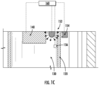
- FIGS. 1A-C are perspective views of an example of a gas detector 100, in accordance with one or more embodiments.
- gas detector 100 may include a membrane 120, a gas sensor 140, and a radiation detection system 150 (which may be referred to herein as a photosensor).
- gas detector 100 may include a controller (shown in FIGS. 1B-C ) operatively connected to one or more components of gas detector 100.
- the controller may be configured to control one or more operations of gas detector 100.
- controller may include one or more processors configured to execute instructions stored on a memory to perform one or more operations of gas detector 100 described herein.
- Other components known to one of ordinary skill in the art may be included in the controller or in gas detector 100 to gather, process, transmit, receive, acquire, and provide information used in conjunction with the disclosed embodiments.
- membrane 120 may be configured to form a sensing chamber 130 where gas sensor 140 is located.
- membrane 120 may be a porous membrane, that acts as a barrier, and is configured to allow gas to flow into sensing chamber 130 and reach gas sensor 140 while filtering out other elements (e.g., liquids, dust, debris, etc.).
- the permeability (dependent on the number and size of the pores) of membrane 120 may depend on type of gas the gas detector 100 is configured to detect (e.g., different membranes with different permeabilities may be used in different gas detectors, depending on the gas to be detected).
- Membrane 120 may be any barrier which allows gas to flow to the sensing chamber and prevents other elements from reaching the gas sensor.
- membrane 120 may be a hydrophobic membrane configured to repel and prevent liquids (e.g., water) from reaching sensing chamber 130.
- membrane 120 may be flexible.
- membrane 120 may contract, expand, flex, or change shape as a result of accumulated elements (e.g., liquids, dust, debris, dirt, etc.) or applied force on one or more walls of its surfaces.
- membrane 120 may be consisting of porous sintered metal.
- Radiation detection system 150 may be configured to generate output signals related to radiation through membrane 120.
- radiation detection system 150 may be configured to measure the amount of radiation that passes through one or more walls of the membrane 120. This measurement may indicate a condition of membrane 120 (e.g., clean, dirty, clogged, damaged, missing, etc.).
- the amount of radiation may also indicate a degree of blockage of one or more walls of the membrane.
- the amount of radiation may indicate presence or absence of the membrane.
- radiation detection system 150 may include a radiation source 152 and a radiation detector 154. Radiation source 152 may be configured to generate radiation and detector 154 may configured to detect the generated radiation after it passes through one or more walls of membrane 120.
- radiation source 152 may be configured to generate electromagnetic radiation having different wavelengths.
- the type of radiation e.g., the wavelength of the radiation
- radiation source 152 may be configured to generate visible light, infrared light, ultraviolet light, or other wavelength electromagnetic radiation.
- radiation detection system 150 (or source 152) may include an aperture or collimator for directing radiation to detector 154 and to limit the detection of light that has not traveled the intended path from the source.
- Detector 154 may be configured to determine the amount of radiation that passes through the one or more walls of membrane 120 (based on the detected radiation). For example, in some embodiments, detector 154 may be configured to detect one or more wavelengths generated by radiation source 152 after it passes through the membrane. The wavelength band may be selectively filtering the radiation at the source or at the detector(s). In some embodiments, the selection may further be to optimize for scatter by particles (e.g., sand, dirt, and/or other particles); or by selective absorption of light by contaminants (e.g., water, solvents, condensing gases oils, or other contaminants). In some embodiments, detector 154 may include control electronics for determining the amount of radiation detected by the detector 154.
- particles e.g., sand, dirt, and/or other particles
- contaminants e.g., water, solvents, condensing gases oils, or other contaminants.
- detector 154 may include control electronics for determining the amount of radiation detected by the detector 154.
- detector 154 may be configured to modulate, demodulate, amplify, and/or select specific wavelengths from the radiation received.
- controller 160 may provide the control electronics operations for the detector 154.
- Detectors may include, but are not limited to, pyrodetectors, bolometers, photoresistors, photoconductors, photocells, and/or photodiodes.
- the radiation source 152 and the radiation detector 154 may be placed on opposite sides of membrane 120.
- radiation source 152 is placed inside sensing chamber 130, while detector 154 is placed outside the sensing chamber.
- this is not intended to be limiting.
- Other configurations of radiation detection system 150 may be used and are consistent with the present invention.
- radiation source 152 may be placed outside sensing chamber 130 and detector 154 may be placed inside the sensing chamber.
- radiation source 152 and detector 154 may be placed on the same side of the membrane 120 (e.g., both inside, or both outside the sensing chamber).
- a radiation reflector may be placed on the opposite side of the membrane to reflect the radiation that passes through the membrane back to the detector for radiation measurements.
- radiation source 152 and detector 154 may both be placed inside the sensing chamber 130.
- a radiation reflector e.g., reflective or light scattering surface, a mirror or other radiation non-absorbing element
- the radiation reflector may be configured to reflect the radiation that passes through the membrane back to detector 154 inside the chamber for radiation measurements.
- radiation source 152 and detector 154 may both be placed outside the sensing chamber 130 and the radiation reflector may be placed inside sensing chamber 130.
- radiation source 152 may be modulated and sensors or sensor signals may be demodulated to reduce effects of detected radiation from other sources.
- FIGS. 1A-B show a radiation detection system 150 having a single radiation detector 154.
- radiation detection system 150 may include two detectors placed on either side of the membrane (outer surface and inner surface). In these cases, comparison of measurements from the detectors may be used to determine the condition of the membrane.
- FIG. 1C illustrates an example of radiation detection system 150 including a second radiation detector 156 placed on the same side of the radiation source 152. Second detector 156 may be configured to detect radiation directly from radiation source 152 (i.e., without going through the membrane). In this example, radiation source 152 and second detector 156 are both inside sensing chamber 130, and detector 154 is outside the chamber.
- radiation source 152 and second detector 156 may be both outside sensing chamber 130, and detector 154 may be inside the chamber.
- a difference in radiation measurements from detector 154 and the second detector 156 may be indicative of whether the membrane is blocked.
- membrane 120 may be determined to be clogged if the difference between the radiation measurements reaches a pre-determined value.
- radiation detection system 150 may include one or more of a beamsplitter and/or additional filters between source 152 and the detectors 154 (and/or 156) to adjust the amount of light in the selected wavelength bands from the source falling on the detectors.
- Controller 160 may be configured to control one or more operations of gas detector 100.
- controller 160 is operatively connected to membrane 120, radiation detection system 150, sensor 140, and/or other components of gas detector 100.
- controller 160 (shown in FIG. 1B ) may control operations of radiation detection system 150.
- controller 160 may activate radiation detection system 150.
- some, or all operations of control electronics of radiation detection system 150 may be performed by controller 160.
- controller 160 may be configured to determine an amount of radiation transmitted through one or more walls of membrane 120 based on output signals from radiation detection system 150 (e.g., from detector 154). For example, controller 160 may determine the amount of radiation based on radiation detected by detector 154.
- the forms of the invention shown in the drawings and described herein are to be taken as examples of embodiments.
- Other types of the gas detector components may be used and are consistent with the present invention.
- the barrier may be the weather shield.
- more than one radiation source may be used.
- a plurality of sensors may be used to investigate the blockages from specific materials of interest (e.g. water, hydrocarbons, sand etc.)
- controller 160 may be configured to determine a radiation change through membrane 120 based on the determined amount of radiation. For example, controller 160 may be configured to determine the radiation change by comparing the determined amount of radiation with previous measurements (e.g., when membrane 120 was clean, when gas detector was first installed, or when membrane was serviced, etc.). In some embodiments, where radiation detection system 150 includes two detectors placed on either side of the membrane (e.g., inside or outside the sensing chamber), controller 160 may be configured to determine radiation change (or difference) by comparing radiation from the detector inside the sensing chamber with the detector outside the sensing chamber.
- controller 160 may be configured to determine a condition of membrane 120. For example, controller 160 may be configured to determine whether membrane 120 is clean, dirty, clogged, damaged, missing, etc. In some embodiments, controller 160 may be configured to determine a condition of membrane 120 based on the measured (or determined) amount of radiation transmitted through membrane 120. In some embodiments, controller 160 may determine presence of blockage (e.g., caused by debris, liquids, or dirt on the membrane) responsive to the amount of radiation reaching a radiation threshold. In some embodiments, the radiation threshold may be determined by the manufacturer, a user, or controller 160. In some embodiments, the radiation threshold may be determined based on one or more of the type of gas detector, type of membrane (e.g., porosity, radiation permeability, etc.), type of gas inside the chamber, membrane condition, and previous radiation measurements.
- the type of gas detector e.g., porosity, radiation permeability, etc.
- controller 160 may be configured to determine the condition of membrane 120 based on radiation change. For example, in these embodiments, controller 160 may determine a first amount of radiation transmitted through the membrane (e.g., when membrane is clean). Controller 160 may subsequently determine the change in the amount of radiation (e.g., via subsequent one or more radiation measurements) and determine the condition of the membrane based on the radiation change. In some embodiments, controller 160 may determine that membrane 120 is clogged (or damaged or missing) responsive to the determined radiation change reaching a radiation change threshold. In some embodiments, the radiation change threshold may be determined based on one or more the type of gas detector, type of membrane (e.g., porosity, radiation permeability, etc.), type of gas inside the chamber, membrane condition, and previous radiation measurements.
- the type of gas detector e.g., porosity, radiation permeability, etc.
- controller 160 may be configured to determine the condition of membrane 120 based on radiation change between the inside and the outside of the sensing chamber (e.g., in cases where the radiation detection system includes a detector inside the sensing chamber and a detector outside the sensing chamber). For example, in these embodiments, controller 160 may determine a second amount of radiation (e.g., directly from the radiation source without going through the membrane) and determine whether the membrane is blocked based on a difference between the determined radiation measurements. In some embodiments, controller 160 may determine that membrane 120 is clogged (or damaged or missing) responsive to the determined difference in the radiation measurements reaching a threshold value for the difference in radiation. In some embodiments, the threshold may be defined with respect to a simultaneous measurement on the second detector that detects radiation directly from the radiation source. In some embodiments, the radiation threshold value may be determined based on one or more the type of gas detector, type of membrane (e.g., porosity, radiation permeability, etc.), type of gas inside the chamber, membrane condition, and previous radiation measurements.
- the type of gas detector
- controller 160 may be configured to determine (or estimate) an amount of blockage of the membrane based on the determined membrane radiation (radiation change, or radiation difference). In some embodiments, controller 160 may be configured to determine (or estimate) a remaining operational life of the membrane based on the determined radiation, radiation change, or radiation ratio. For example, controller 160 may indicate whether or when the membrane should be cleaned or replaced based the determined radiation.
- controller 160 may be configured to automatically activate radiation detection system 150 (e.g., by activating the radiation source and the detector to measure radiation transmitted through membrane 120).
- the controller 160 may activate radiation detection system 150 periodically to check (or test) for blockage in the membrane.
- the controller may check for blockage on pre-determined schedule, on demand (e.g., locally, or remotely via a communication network), or based on previous test results.
- the controller 160 may be configured to change testing schedule (e.g., may check for blockage before a pre- scheduled test).
- the controller may skip a scheduled check for blockage.
- controller 160 may be configured to generate a feedback or alert including one or more of the radiation measurements, a condition of the membrane, determination of whether the membrane is blocked, the amount of blockage, or an estimation of remaining operational life of the membrane.
- the feedback may be displayed on a display of the gas detector.
- controller 160 may generate an alarm (e.g., audible, or visual alarm) responsive to determining the condition of the membrane (e.g., lights, or alarm sounds).
- an alarm e.g., audible, or visual alarm
- different types of alarms may be used based on the condition of the membrane. For example, green light if the barrier is clean, yellow if it's beginning to clog, red light it's nearly or completely blocked, torn, or missing, etc.
- different audible alarms may be based on the condition of the membrane.
- the feedback/alert may be sent to a user device (e.g., via a communication network) which may allow users to remotely monitor operations of the gas detector (e.g., detecting the condition of the membrane).
- controller 160 may be configured to communicate with a maintenance scheduling system to trigger a maintenance call based on the determined condition of the membrane. With this advance warning, the end-user may schedule maintenance to replace the membrane prior to failure and reduce costly down-time or gas detector failures due to blocked membranes.
- FIGS. 2A-B are perspective views of an example of a combustible gas detector 200, in accordance with one or more embodiments.
- gas detector 200 may include a gas sensor 240 and a radiation detection system 250 (252, 254).
- gas detector 200 may include a controller 260 (shown in FIG. 2B ) operatively connected to one or more components of gas detector 200.
- the controller may be configured to control one or more operations of gas detector 200.
- controller may include one or more processors configured to execute instructions stored on a memory to perform one or more operations of gas detector 200 described herein.
- Other components known to one of ordinary skill in the art may be included in the controller or in gas detector 200 to gather, process, transmit, receive, acquire, and provide information used in conjunction with the disclosed embodiments.
- gas sensor 240 may be configured to detect (or measure) gas within enclosure 201.
- the enclosure 201 may be configured to house one or more components of gas detector 200.
- gas sensor 240 may be housed in enclosure 201.
- gas sensor 240 may be detachably connected to enclosure 201 to facilitate removal of gas sensor 240 (e.g., for maintenance, repair, malfunction, or if gas detector 200 is used to detect a different gas).
- enclosure 201 may include a sensing interface 202 configured to act as a barrier which allows gas to flow into enclosure 201 and reach gas sensor 240 while filtering out other elements (e.g., liquids, dust, debris, etc.).
- sensing interface 202 may include a porous material.
- a porous membrane e.g., hydrophobic membrane
- sinter or other porous material.
- Radiation detection system 250 may be configured to generate output signals related to radiation through sensing interface 202.
- radiation detection system 250 may be similar to radiation detection system 150 described above.
- radiation detection system 250 may be configured to measure the amount of radiation that passes through sensing interface 202. This measurement may indicate a condition of sensing interface 202 (e.g., clean, dirty, clogged, damaged, missing, etc.).
- the amount of detected radiation at the radiation detection systems may also indicate a degree of blockage of sensing interface 202.
- radiation detection system 250 may include a radiation source 252, a radiation detector 254, and a radiation reflector 258.
- radiation reflector 258 may be a reflective or light scattering surface, a mirror, or other radiation partial absorbing or non-absorbing element. Radiation reflector 258 may be configured to reflect the radiation that passes through the membrane 202 back to detector 254.
- radiation source 252 and detector 254 may be placed inside enclosure 201.
- Radiation source 252 may be configured to generate radiation and detector 254 may configured to detect the generated radiation after it passes through sensing interface 202.
- gas detector 200 may include a radiation reflector 258 placed outside of enclosure 201. The radiation reflector 258 may be configured to reflect the radiation that passes through the sensing interface 202 back to detector 254 inside the enclosure 201 for radiation measurements.
- radiation source 252 and detector 254 may both be placed outside the enclosure 201 and the radiation reflector 258 may be placed inside enclosure 201.
- Controller 260 may be configured to control one or more operations of gas detector 200.
- controller 260 is operatively connected to radiation detection system 250, gas sensor 240, and/or other components of gas detector 200.
- controller 260 may control operations of radiation detection system 250.
- controller 260 may activate radiation detection system 250.
- some, or all operations of control electronics of radiation detection system 250 may be performed by controller 260.
- controller 260 may be configured to determine an amount of radiation transmitted through sensor interface 202 based on output signals from radiation detection system 250 (e.g., from detector 254).
- controller 260 may determine the amount of radiation based on radiation detected by detector 254.
- controller 260 may be configured to determine a radiation change through sensing interface 202 based on the determined amount of radiation (e.g., by comparing the determined amount of radiation with previous measurements). In some embodiments, controller 260 may be configured to determine a condition of sensing interface 202 (e.g., clean, dirty, clogged, damaged, missing, etc.) based on the measured amount of radiation transmitted through sensing interface 202. In some embodiments, controller 260 may determine presence of blockage (e.g., caused by debris, liquids, or dirt on the membrane) responsive to the amount of radiation reaching a radiation threshold. In some embodiments, the radiation threshold may be determined by the manufacturer, a user, or controller 260. In some embodiments, the radiation threshold may be determined based on one or more of the type of gas detector, type of sensing interface (e.g., type of membrane or type of sinter), ambient environment conditions, membrane condition, and previous radiation measurements.
- a condition of sensing interface 202 e.g., clean, dirty, clogged,
- controller 260 may be configured to determine (or estimate) an amount of blockage of sensing interface 202 based on the determined radiation (or radiation change). In some embodiments, controller 260 may be configured to determine (or estimate) a remaining operational life of the membrane based on the determined radiation, or radiation change. For example, controller 260 may indicate whether or when the sensing interface should be cleaned or replaced based the determined radiation.
- controller 260 may be configured to automatically activate radiation detection system 250 (e.g., by activating the radiation source and the detector to measure radiation transmitted through sensing interface 202).
- the controller 260 may activate radiation detection system 250 periodically to check (or test) for blockage in the sensing interface 202.
- the controller may check for blockage on pre-determined schedule, on demand (e.g., locally, or remotely via a communication network), or based on previous test results.
- the controller 260 may be configured to change testing schedule (e.g., may check for blockage before a pre- scheduled test).
- the controller may skip a scheduled check for blockage.
- controller 260 may be configured to generate a feedback or alert including one or more of the radiation measurements, a condition of the sensing interface, determination of whether the sensing interface is blocked, the amount of blockage, or an estimation of remaining operational life of the sensing interface.
- the feedback may be displayed on a display of the gas detector.
- controller 260 may generate an alarm responsive to determining the condition of the sensing interface.
- the feedback/alert may be sent to a user device (e.g., via a communication network) which may allow users to remotely monitor operations of the gas detector (e.g., detecting the condition of the membrane).
- controller 260 may be configured to communicate with a maintenance scheduling system to trigger a maintenance call based on the determined condition of the sensing interface.
- FIG. 2C is a perspective view of an example of a combustible gas detector 200, in accordance with one or more embodiments.
- sensing interface 202 may include a window 204.
- the window may be located in the detector housing (as shown in FIG. 2D ).
- the condition of window 204 may be indicative of the condition of the barrier (e.g., sensing interface 202).
- radiation reflector 258 may be configured to reflect the radiation that passes through window 204 back to detector 254.
- controller 260 may be configured to determine a condition of sensing interface 202 (e.g., whether it is clean, dirty, clogged, damaged, missing, etc.) based on the measured amount of radiation transmitted through window 204. In some embodiments, controller 260 may determine the condition of sensing interface 202 responsive to the amount of radiation through window 204 reaching a radiation threshold. In some embodiments, the radiation threshold may be determined based on window 204 composition (e.g., glass, plastic, etc.).
- FIGS. 2D is a perspective view of an example of a combustible gas detector 200, in accordance with one or more embodiments. FIG. 2D shows an example where window 204 is located in hosing 201.
- FIG. 3 shows a flow diagram illustrating an example of a method 300 for detecting membrane blockage in a gas detector, in accordance with one or more embodiments of the present invention.
- the gas detector comprises a membrane defining a sensing chamber of the detector, and a radiation detection system (e.g., as described above).
- one or more output signals related to radiation transmitted through the membrane may be generated.
- operation 302 may be performed by a radiation detection system the same as or similar to radiation detection system 150 (shown in FIGS.1A-C and described herein).
- an amount of radiation transmitted through the membrane may be determined.
- operation 304 may be performed by a controller the same as or similar to controller 160 (shown in FIGs.IB-C and described herein).
- a condition of the membrane may be determined based on the determined amount of radiation.
- operation 306 may be performed by controller the same as or similar to controller 160 (shown in FIGs.1B-C and described herein).
- the word “may” is used in a permissive sense (i.e., meaning having the potential to), rather than the mandatory sense (i.e., meaning must).
- the words “include”, “including”, and “includes” and the like mean including, but not limited to.
- the singular forms “a,” “an,” and “the” include plural referents unless the content explicitly indicates otherwise.
- statements that one value or action is "based on" another condition or value encompass both instances in which the condition or value is the sole factor and instances in which the condition or value is one factor among a plurality of factors.
- statements that "each" instance of some collection have some property should not be read to exclude cases where some otherwise identical or similar members of a larger collection do not have the property, i.e., each does not necessarily mean each and every.
Applications Claiming Priority (1)
| Application Number | Priority Date | Filing Date | Title |
|---|---|---|---|
| US202263268966P | 2022-03-07 | 2022-03-07 |
Publications (1)
| Publication Number | Publication Date |
|---|---|
| EP4242639A1 true EP4242639A1 (fr) | 2023-09-13 |
Family
ID=85505417
Family Applications (1)
| Application Number | Title | Priority Date | Filing Date |
|---|---|---|---|
| EP23160283.0A Pending EP4242639A1 (fr) | 2022-03-07 | 2023-03-06 | Systèmes et procédés de détection de blocage dans des détecteurs de gaz |
Country Status (2)
| Country | Link |
|---|---|
| US (1) | US20230280255A1 (fr) |
| EP (1) | EP4242639A1 (fr) |
Citations (9)
| Publication number | Priority date | Publication date | Assignee | Title |
|---|---|---|---|---|
| JPS5214399A (en) * | 1975-07-24 | 1977-02-03 | Oki Electric Ind Co Ltd | Dust cleaner mesh choking monitor of smoke sensor |
| JPH02181297A (ja) * | 1989-01-06 | 1990-07-16 | Oki Denki Bosai Kk | 試験機能付煙感知器 |
| JPH04250345A (ja) * | 1991-01-28 | 1992-09-07 | Matsushita Electric Works Ltd | 煙感知器 |
| EP2330577A1 (fr) * | 2009-12-04 | 2011-06-08 | Atral-Secal GmbH | Détecteur de fumée doté d'une surveillance du recouvrement infrarouge |
| JP2016070505A (ja) * | 2014-09-26 | 2016-05-09 | 東芝キヤリア株式会社 | エアフィルタの目詰まり検知装置、および、それを備えた空調機 |
| EP3113133A2 (fr) * | 2015-06-29 | 2017-01-04 | Atral-Secal GmbH | Detecteur de fumee dote d'un dispositif combine de detection de particule et de recouvrement de l'orifice d'entree de fumee |
| WO2019153665A1 (fr) * | 2018-02-08 | 2019-08-15 | 芜湖美智空调设备有限公司 | Procédé de détection de la propreté d'un tamis filtrant, capteur de propreté de tamis filtrant et appareil de traitement d'air |
| CN111044685A (zh) * | 2019-12-31 | 2020-04-21 | 佛山华谱测智能科技有限公司 | 一种scr出口气体成分在线网格式巡回检测系统 |
| US10639577B1 (en) * | 2018-01-17 | 2020-05-05 | Filtersmarts, Inc | Clogged dust filter monitor |
-
2023
- 2023-02-09 US US18/167,037 patent/US20230280255A1/en active Pending
- 2023-03-06 EP EP23160283.0A patent/EP4242639A1/fr active Pending
Patent Citations (9)
| Publication number | Priority date | Publication date | Assignee | Title |
|---|---|---|---|---|
| JPS5214399A (en) * | 1975-07-24 | 1977-02-03 | Oki Electric Ind Co Ltd | Dust cleaner mesh choking monitor of smoke sensor |
| JPH02181297A (ja) * | 1989-01-06 | 1990-07-16 | Oki Denki Bosai Kk | 試験機能付煙感知器 |
| JPH04250345A (ja) * | 1991-01-28 | 1992-09-07 | Matsushita Electric Works Ltd | 煙感知器 |
| EP2330577A1 (fr) * | 2009-12-04 | 2011-06-08 | Atral-Secal GmbH | Détecteur de fumée doté d'une surveillance du recouvrement infrarouge |
| JP2016070505A (ja) * | 2014-09-26 | 2016-05-09 | 東芝キヤリア株式会社 | エアフィルタの目詰まり検知装置、および、それを備えた空調機 |
| EP3113133A2 (fr) * | 2015-06-29 | 2017-01-04 | Atral-Secal GmbH | Detecteur de fumee dote d'un dispositif combine de detection de particule et de recouvrement de l'orifice d'entree de fumee |
| US10639577B1 (en) * | 2018-01-17 | 2020-05-05 | Filtersmarts, Inc | Clogged dust filter monitor |
| WO2019153665A1 (fr) * | 2018-02-08 | 2019-08-15 | 芜湖美智空调设备有限公司 | Procédé de détection de la propreté d'un tamis filtrant, capteur de propreté de tamis filtrant et appareil de traitement d'air |
| CN111044685A (zh) * | 2019-12-31 | 2020-04-21 | 佛山华谱测智能科技有限公司 | 一种scr出口气体成分在线网格式巡回检测系统 |
Also Published As
| Publication number | Publication date |
|---|---|
| US20230280255A1 (en) | 2023-09-07 |
Similar Documents
| Publication | Publication Date | Title |
|---|---|---|
| KR100955994B1 (ko) | 산란광 신호를 측정하기 위한 방법 및 상기 방법을구현하는 산란광 검출기 | |
| US7129847B2 (en) | Detector with dust filter and airflow monitor | |
| KR101069042B1 (ko) | 유동체가 제1 속도로 통과하여 흐르는 입구를 갖는 입자탐지기를 위한 챔버 구성 | |
| EP2452323B1 (fr) | Conditionnement de chambre | |
| TWI570670B (zh) | 煙霧感測器 | |
| CN104897536A (zh) | 过滤器旁路技术 | |
| US11828687B2 (en) | Detection of a clogged filter in an aspirating detection system | |
| CN110892460B (zh) | 带有室内空气质量检测和监测的无腔室型烟雾检测器 | |
| KR20200033619A (ko) | 미세먼지 감지 센서 어셈블리 | |
| KR101753873B1 (ko) | 적외선광 산란보정 비분산형 연기감지장치 | |
| EP3894837B1 (fr) | Étalonnage d'un détecteur optique | |
| CN102762972B (zh) | 用于确定散射光测量设备的测量结果质量的方法和装置 | |
| EP4242639A1 (fr) | Systèmes et procédés de détection de blocage dans des détecteurs de gaz | |
| US20210364422A1 (en) | Calibration of optical detector | |
| US20060192968A1 (en) | Optical assembly | |
| JP6948703B2 (ja) | 光学監視装置 | |
| US11892396B2 (en) | Gas sensor with two switchable filters and method for operating such a gas sensor | |
| US20220050039A1 (en) | Photoelectric smoke sensor tube | |
| EP3635700B1 (fr) | Procédé de surveillance de l'état d'un couvercle de protection d'un dispositif de détection | |
| JP4566659B2 (ja) | 光検出器 | |
| EP3460428A1 (fr) | Détecteur de longueur d'onde double | |
| AU706461B2 (en) | Filter integrity monitoring system | |
| AU2004207146A1 (en) | Optical assembly |
Legal Events
| Date | Code | Title | Description |
|---|---|---|---|
| PUAI | Public reference made under article 153(3) epc to a published international application that has entered the european phase |
Free format text: ORIGINAL CODE: 0009012 |
|
| STAA | Information on the status of an ep patent application or granted ep patent |
Free format text: STATUS: THE APPLICATION HAS BEEN PUBLISHED |
|
| AK | Designated contracting states |
Kind code of ref document: A1 Designated state(s): AL AT BE BG CH CY CZ DE DK EE ES FI FR GB GR HR HU IE IS IT LI LT LU LV MC ME MK MT NL NO PL PT RO RS SE SI SK SM TR |
|
| STAA | Information on the status of an ep patent application or granted ep patent |
Free format text: STATUS: REQUEST FOR EXAMINATION WAS MADE |
|
| 17P | Request for examination filed |
Effective date: 20240312 |
|
| RBV | Designated contracting states (corrected) |
Designated state(s): AL AT BE BG CH CY CZ DE DK EE ES FI FR GB GR HR HU IE IS IT LI LT LU LV MC ME MK MT NL NO PL PT RO RS SE SI SK SM TR |