EP4241685A2 - Medizinisches system und verfahren zur herstellung davon - Google Patents
Medizinisches system und verfahren zur herstellung davon Download PDFInfo
- Publication number
- EP4241685A2 EP4241685A2 EP23169503.2A EP23169503A EP4241685A2 EP 4241685 A2 EP4241685 A2 EP 4241685A2 EP 23169503 A EP23169503 A EP 23169503A EP 4241685 A2 EP4241685 A2 EP 4241685A2
- Authority
- EP
- European Patent Office
- Prior art keywords
- housing
- protective cap
- medical system
- cap
- sterility
- Prior art date
- Legal status (The legal status is an assumption and is not a legal conclusion. Google has not performed a legal analysis and makes no representation as to the accuracy of the status listed.)
- Granted
Links
Images
Classifications
-
- A—HUMAN NECESSITIES
- A61—MEDICAL OR VETERINARY SCIENCE; HYGIENE
- A61B—DIAGNOSIS; SURGERY; IDENTIFICATION
- A61B5/00—Measuring for diagnostic purposes; Identification of persons
- A61B5/68—Arrangements of detecting, measuring or recording means, e.g. sensors, in relation to patient
- A61B5/6801—Arrangements of detecting, measuring or recording means, e.g. sensors, in relation to patient specially adapted to be attached to or worn on the body surface
- A61B5/6843—Monitoring or controlling sensor contact pressure
-
- A—HUMAN NECESSITIES
- A61—MEDICAL OR VETERINARY SCIENCE; HYGIENE
- A61B—DIAGNOSIS; SURGERY; IDENTIFICATION
- A61B5/00—Measuring for diagnostic purposes; Identification of persons
- A61B5/145—Measuring characteristics of blood in vivo, e.g. gas concentration or pH-value ; Measuring characteristics of body fluids or tissues, e.g. interstitial fluid or cerebral tissue
- A61B5/14503—Measuring characteristics of blood in vivo, e.g. gas concentration or pH-value ; Measuring characteristics of body fluids or tissues, e.g. interstitial fluid or cerebral tissue invasive, e.g. introduced into the body by a catheter or needle or using implanted sensors
-
- A—HUMAN NECESSITIES
- A61—MEDICAL OR VETERINARY SCIENCE; HYGIENE
- A61B—DIAGNOSIS; SURGERY; IDENTIFICATION
- A61B5/00—Measuring for diagnostic purposes; Identification of persons
- A61B5/145—Measuring characteristics of blood in vivo, e.g. gas concentration or pH-value ; Measuring characteristics of body fluids or tissues, e.g. interstitial fluid or cerebral tissue
- A61B5/14532—Measuring characteristics of blood in vivo, e.g. gas concentration or pH-value ; Measuring characteristics of body fluids or tissues, e.g. interstitial fluid or cerebral tissue for measuring glucose, e.g. by tissue impedance measurement
-
- A—HUMAN NECESSITIES
- A61—MEDICAL OR VETERINARY SCIENCE; HYGIENE
- A61B—DIAGNOSIS; SURGERY; IDENTIFICATION
- A61B5/00—Measuring for diagnostic purposes; Identification of persons
- A61B5/145—Measuring characteristics of blood in vivo, e.g. gas concentration or pH-value ; Measuring characteristics of body fluids or tissues, e.g. interstitial fluid or cerebral tissue
- A61B5/1468—Measuring characteristics of blood in vivo, e.g. gas concentration or pH-value ; Measuring characteristics of body fluids or tissues, e.g. interstitial fluid or cerebral tissue using chemical or electrochemical methods, e.g. by polarographic means
- A61B5/1486—Measuring characteristics of blood in vivo, e.g. gas concentration or pH-value ; Measuring characteristics of body fluids or tissues, e.g. interstitial fluid or cerebral tissue using chemical or electrochemical methods, e.g. by polarographic means using enzyme electrodes, e.g. with immobilised oxidase
- A61B5/14865—Measuring characteristics of blood in vivo, e.g. gas concentration or pH-value ; Measuring characteristics of body fluids or tissues, e.g. interstitial fluid or cerebral tissue using chemical or electrochemical methods, e.g. by polarographic means using enzyme electrodes, e.g. with immobilised oxidase invasive, e.g. introduced into the body by a catheter or needle or using implanted sensors
-
- A—HUMAN NECESSITIES
- A61—MEDICAL OR VETERINARY SCIENCE; HYGIENE
- A61B—DIAGNOSIS; SURGERY; IDENTIFICATION
- A61B5/00—Measuring for diagnostic purposes; Identification of persons
- A61B5/68—Arrangements of detecting, measuring or recording means, e.g. sensors, in relation to patient
- A61B5/6801—Arrangements of detecting, measuring or recording means, e.g. sensors, in relation to patient specially adapted to be attached to or worn on the body surface
- A61B5/683—Means for maintaining contact with the body
- A61B5/6832—Means for maintaining contact with the body using adhesives
-
- A—HUMAN NECESSITIES
- A61—MEDICAL OR VETERINARY SCIENCE; HYGIENE
- A61B—DIAGNOSIS; SURGERY; IDENTIFICATION
- A61B5/00—Measuring for diagnostic purposes; Identification of persons
- A61B5/68—Arrangements of detecting, measuring or recording means, e.g. sensors, in relation to patient
- A61B5/6846—Arrangements of detecting, measuring or recording means, e.g. sensors, in relation to patient specially adapted to be brought in contact with an internal body part, i.e. invasive
-
- A—HUMAN NECESSITIES
- A61—MEDICAL OR VETERINARY SCIENCE; HYGIENE
- A61B—DIAGNOSIS; SURGERY; IDENTIFICATION
- A61B2560/00—Constructional details of operational features of apparatus; Accessories for medical measuring apparatus
- A61B2560/02—Operational features
- A61B2560/0204—Operational features of power management
- A61B2560/0214—Operational features of power management of power generation or supply
-
- A—HUMAN NECESSITIES
- A61—MEDICAL OR VETERINARY SCIENCE; HYGIENE
- A61B—DIAGNOSIS; SURGERY; IDENTIFICATION
- A61B2560/00—Constructional details of operational features of apparatus; Accessories for medical measuring apparatus
- A61B2560/04—Constructional details of apparatus
- A61B2560/0456—Apparatus provided with a docking unit
-
- A—HUMAN NECESSITIES
- A61—MEDICAL OR VETERINARY SCIENCE; HYGIENE
- A61B—DIAGNOSIS; SURGERY; IDENTIFICATION
- A61B2560/00—Constructional details of operational features of apparatus; Accessories for medical measuring apparatus
- A61B2560/06—Accessories for medical measuring apparatus
- A61B2560/063—Devices specially adapted for delivering implantable medical measuring apparatus
-
- A—HUMAN NECESSITIES
- A61—MEDICAL OR VETERINARY SCIENCE; HYGIENE
- A61B—DIAGNOSIS; SURGERY; IDENTIFICATION
- A61B2562/00—Details of sensors; Constructional details of sensor housings or probes; Accessories for sensors
- A61B2562/12—Manufacturing methods specially adapted for producing sensors for in-vivo measurements
-
- A—HUMAN NECESSITIES
- A61—MEDICAL OR VETERINARY SCIENCE; HYGIENE
- A61B—DIAGNOSIS; SURGERY; IDENTIFICATION
- A61B2562/00—Details of sensors; Constructional details of sensor housings or probes; Accessories for sensors
- A61B2562/24—Hygienic packaging for medical sensors; Maintaining apparatus for sensor hygiene
- A61B2562/242—Packaging, i.e. for packaging the sensor or apparatus before use
-
- A—HUMAN NECESSITIES
- A61—MEDICAL OR VETERINARY SCIENCE; HYGIENE
- A61B—DIAGNOSIS; SURGERY; IDENTIFICATION
- A61B2562/00—Details of sensors; Constructional details of sensor housings or probes; Accessories for sensors
- A61B2562/24—Hygienic packaging for medical sensors; Maintaining apparatus for sensor hygiene
- A61B2562/247—Hygienic covers, i.e. for covering the sensor or apparatus during use
Definitions
- the invention relates to a medical system and to a method of manufacturing a medical system.
- the medical system specifically may be used for detecting at least one analyte in a body fluid, such as a body fluid contained in a body tissue.
- the medical system specifically may be used for inserting an analyte sensor contained in the system into the body tissue of the user.
- the medical system may be applied both in the field of home care and in the field of professional care, such as in hospitals. Other applications are feasible.
- analytes can include by way of example, but not exclusively, blood glucose, lactate, cholesterol or other types of analytes and metabolites.
- analytes can include by way of example, but not exclusively, blood glucose, lactate, cholesterol or other types of analytes and metabolites.
- the invention will be described in the following text with reference to blood-glucose monitoring. However, additionally or alternatively, the invention can also be applied to other types of analytes, such as the analytes mentioned above.
- electrochemical sensors are used which transcutaneously are inserted into the body tissue of the user.
- the sensors typically comprise an elongated flexible substrate onto which a plurality of electrodes, including one or more working electrodes and one or more further electrodes such as one or more counter electrodes and/or one or more reference electrodes are applied.
- US 2010/0200538 A1 discloses methods for fabricating analyte sensor components, using IC- or MEMs-based fabrication techniques and sensors prepared therefrom.
- Fabrication of the analyte sensor component comprises providing an inorganic substrate having deposited thereon a release layer, a first flexible dielectric layer and a second flexible dielectric layer insulating there between electrodes, contact pads and traces connecting the electrodes and the contact pads of a plurality of sensors. Openings are provided in one of the dielectric layers over one or more of the electrodes to receive an analyte sensing membrane for the detection of an analyte of interest and for electrical connection with external electronics.
- the plurality of fabricated sensor components are lifted off the inorganic substrate.
- EP 2348964 B1 discloses an electrode system for measuring the concentration of an analyte under in-vivo conditions.
- the electrode system comprises a counter-electrode having an electrical conductor, a working electrode having an electrical conductor on which an enzyme layer containing immobilized enzyme molecules for catalytic conversion of the analyte is arranged, and a diffusion barrier that slows the diffusion of the analyte from body fluid surrounding the electrode system to enzyme molecules down.
- the invention provides the enzyme layer in the form of multiple fields that are arranged on the conductor of the working electrode at a distance from each other.
- one challenge resides in appropriate devices for inserting the analyte sensor into the body tissue.
- a further challenge resides in the fact that, in many systems, the analyte sensor has to be electrically connected to an electronics unit disposed on the surface of the skin of the user.
- Further challenges reside in the overall handling of the medical system which, in many cases, has to be performed by untrained users including children and elderly people, which generally requires easy handling procedures with as little steps as possible.
- WO 2016/012482 A1 discloses an insertion device for inserting an analyte sensor into a body tissue, the insertion device having an insertion needle holder and a drive mechanism for linearly driving the insertion needle holder in a longitudinal direction.
- the drive mechanism comprises at least one actuator for actuating the drive mechanism.
- the actuator comprises at least one actuator arm which is pivotable about at least one axle in order to actuate the drive mechanism.
- the insertion device further comprises at least one protection against reuse including at least one locking mechanism.
- the locking mechanism is adapted to at least partially prevent a back-pivoting of the actuator arm in a direction reversing the actuation direction once the actuator arm has been pivoted by at least one threshold angle.
- WO 2016/012497 A1 discloses an insertion device for inserting an analyte sensor into a body tissue.
- the insertion device comprises an insertion needle holder and a drive mechanism for driving the insertion needle holder in a longitudinal direction.
- the drive mechanism comprises at least one actuator for actuating the drive mechanism.
- the drive mechanism comprises a rotor adapted to transform an actuation motion of the actuator into a motion of the insertion needle holder in the longitudinal direction.
- the insertion device further comprises at least one safety lock.
- the safety lock in a locked position, is adapted to at least partially block a rotation of the rotor. In an unlocked position, the safety lock is adapted to permit the rotation of the rotor.
- WO 2017/037191 A1 discloses a kit for determining a concentration of at least one analyte in a body fluid of a user, comprising: a) a sensor module comprising i. at least one sensor element adapted to determine the concentration of the analyte, wherein the sensor element is at least partly implantable into a body tissue of the user; ii.
- control device connected to the sensor element, wherein the control device comprises at least one data collection device adapted to collect measurement data acquired by using the sensor element, wherein the control device further comprises at least one wireless near-field communication device adapted to transmit measurement data, wherein the sensor module comprises a sensor module mechanical interface; b) at least one data reader module adapted to receive measurement data transmitted by the sensor module via wireless near-field communication, wherein the data reader module comprises at least one data storage device and is adapted to store the measurement data; c) at least one data transmission module adapted to receive measurement data transmitted by the sensor module via wireless near-field communication, wherein the data transmission module comprises at least one wireless far-field communication device, wherein the wireless far-field communication device is adapted to transmit at least part of the measurement data to an external device via wireless far-field communication.
- the data reader module and the data transmission module each comprise a mechanical interface adapted to reversibly engage the sensor module mechanical interface, thereby alternatively generating a fixed spatial relationship between the sensor module and the data reader module or the sensor module and the data transmission
- EP 2 991 552 A1 systems, devices, and methods are described for changing the power state of a sensor control device in an in vivo analyte monitoring system in various manners, such as through the use of external stimuli (light, magnetics) and RF transmissions.
- WO 2011/119896 A1 describes an apparatus for insertion of a medical device in the skin of a subject, as well as methods of inserting medical devices.
- Said apparatus includes a sheath, a device support movable between a proximal and distal position, a sharp support movable between a proximal and distal position, a handle movable between a proximal and distal position, and a driver.
- US 2010/286714 A1 describes an inserter device for inserting a medical device into the subcutaneous or intramuscular area of a patient. More specifically, an inserter device is described comprising means for providing a controlled and defined acceleration and deceleration of a penetrating member.
- the inserter device according to the invention comprises a housing (encompassing said penetrating member, a rotating member and driving means for rotating the rotating member around a rotating axis.
- the rotating member comprises transformation means transforming the rotational movement into a longitudinal movement of the penetrating member in the direction of insertion and the transformation means comprises controlling means providing a controlled variation of the velocity of the penetrating member in the direction of insertion.
- US 2007/202488 A1 describes method for determining the relative benefits of products which affect animal epithelial tissue. Also provided is a method for evaluating quantitative changes on one or more affected surfaces of epithelial tissue of a subject caused by a test product.
- US 2016/331284 A1 describes compact medical device inserters, systems incorporating the same, and related methods of use.
- the inserters can include a housing, a sharp support, a sharp body, and a shroud, and can apply a sensor control device to a recipient with a sensor implanted in the recipient's body.
- the shroud can extend from the sensor control device in a position that covers or protects the sensor and a sharp, and can be retracted by pressure placed upon the inserter against the recipient's body to cause the sharp and sensor to penetrate the body, after which the sharp can be automatically withdrawn with the aid of a biasing element.
- a medical system which allows for easy and user-friendly insertion of an analyte sensor into a body tissue, with few handling steps and with a high degree of protection against detrimental mechanical and environmental influences.
- the terms “have”, “comprise” or “include” or any arbitrary grammatical variations thereof are used in a non-exclusive way. Thus, these terms may both refer to a situation in which, besides the feature introduced by these terms, no further features are present in the entity described in this context and to a situation in which one or more further features are present.
- the expressions “A has B”, “A comprises B” and “A includes B” may both refer to a situation in which, besides B, no other element is present in A (i.e. a situation in which A solely and exclusively consists of B) and to a situation in which, besides B, one or more further elements are present in entity A, such as element C, elements C and D or even further elements.
- the terms "at least one”, “one or more” or similar expressions indicating that a feature or element may be present once or more than once typically will be used only once when introducing the respective feature or element.
- the expressions “at least one” or “one or more” will not be repeated, non-withstanding the fact that the respective feature or element may be present once or more than once.
- a medical system In a first aspect of the present invention, a medical system is disclosed.
- the system specifically may be configured for and used for qualitatively and/or quantitatively detecting at least one analyte in a body fluid, such as one or more of the analyte listed above.
- the medical system comprises:
- Components a., b., and c. as listed above specifically may be pre-assembled, such as to form a pre-assembled module, a pre-assembled single unit, a single factory-assembled module.
- This pre-assembled module or unit specifically, may be packaged, as will be outlined in further detail below, e.g. in a blister pack.
- the term "medical system” as used herein is a broad term and is to be given its ordinary and customary meaning to a person of ordinary skill in the art and is not to be limited to a special or customized meaning.
- the term specifically may refer, without limitation, to a system configured for performing at least one medical function.
- the medical system may be configured for qualitatively and/or quantitatively detecting at least one analyte in a body fluid, such as in a body fluid contained in a body tissue of a user.
- the medical system specifically may be configured for performing at least two actions, which are the action of inserting an analytical sensor into the body tissue and to the action of detecting the analyte in the body fluid by using the analytical sensor.
- the medical system specifically may be, in a basic state before use, a unitary system which may be handled as one single piece. After use, which is after insertion of the analyte sensor into the body tissue, the medical system may disassemble into a disposable handling component including an inserter in a used state, and into an analyte sensor unit, with a body mount and the analyte sensor, wherein the body mount may be attached to the skin of the user and wherein the analyte sensor may protrude from the analyte sensor unit into the body tissue.
- housing is a broad term and is to be given its ordinary and customary meaning to a person of ordinary skill in the art and is not to be limited to a special or customized meaning.
- the term specifically may refer, without limitation, to a basically arbitrary element which is configured for fully or partially enclosing one or more components and for providing protection for these one or more components, such as against mechanical influence and/or humidity.
- the housing specifically, may be or may comprise a rigid housing, such as a rigid housing made of one or more of a plastic material, a metallic material or a cardboard material.
- the housing may have a front face which is configured for being disposed on the skin of the user, such as an essentially flat front face.
- the front face may have a rim, with an opening enclosed by the rim, wherein the rim, as an example, is configured for tightening the skin for application of the analyte sensor.
- the housing may comprise, may contain or may encase one or more further components, such as an insertion actuator.
- the term "functional module” is a broad term and is to be given its ordinary and customary meaning to a person of ordinary skill in the art and is not to be limited to a special or customized meaning.
- the term specifically may refer, without limitation, to a module, such as a unitary module made of one or more components, specifically a plurality of interconnected components, which are configured for interacting for performing at least one function, specifically at least one medical function.
- the functional module specifically may be a medical functional module configured for performing at least one medical function, such as for qualitatively and/or quantitatively detecting at least one analyte in a body fluid.
- the term "preassembled” generally refers to the fact that an assembly process has already taken place.
- the medical system comprises the functional module as defined above in a preassembled state, which means the components of the functional module already being assembled, such as by being mechanically and/or electrically interconnected, thereby being ready for use for the at least one function, such as the at least one medical function, e.g. for the at least one analytical function.
- the preassembling specifically may take place in a factory, thereby rendering the preassembled functional module a factory-assembled functional module.
- the medical system may be configured such that the at least one preassembled functional module is fully covered by the combination of the housing and the protective cap, such that the user may not see or manipulate the preassembled functional module without opening the medical device, e.g. without removing the protective cap.
- the term "received in the housing” generally refers to the fact that the preassembled functional module is fully or partially surrounded by the housing.
- the housing may comprise at least one receptacle for receiving the preassembled functional module.
- the receptacle as an example, may be located in a front face of the housing, wherein the receptacle may fully or partially be surrounded by a frame formed e.g. by the housing.
- the receptacle may be covered by the protective cap, such that, when the protective cap is removed from the housing, the functional module is accessible and may be placed on the skin of the user.
- the term "sensor” as used herein is a broad term and is to be given its ordinary and customary meaning to a person of ordinary skill in the art and is not to be limited to a special or customized meaning.
- the term specifically may refer, without limitation, to an arbitrary element or device configured for detecting at least one condition or for measuring at least one measurement variable.
- the sensor specifically may be or may comprise an analyte sensor for at least partial implantation into a body tissue of a user, more specifically an analyte sensor for continuous monitoring of the analyte.
- the sensor specifically may be a monolithic sensor element.
- the term “analytical sensor” is a broad term and is to be given its ordinary and customary meaning to a person of ordinary skill in the art and is not to be limited to a special or customized meaning.
- the term specifically may refer, without limitation, to a sensor according to the definition given above, which is configured for being used for analytical purposes.
- the analytical sensor may be configured for qualitatively and/or quantitatively detecting at least one analyte in a body fluid of the user, such as one or more of the analytes listed above, more specifically glucose.
- the body fluid as an example, may be or may contain one or more of blood or interstitial fluid.
- the analytical sensor specifically may be configured for long-term monitoring of the analyte.
- the analytical sensor as an example, may be configured for being placed into the body tissue and for remaining therein for at least one week, by providing measurement data over this period of use.
- the analytical sensor specifically may be or may comprise an electrochemical analytical sensor, as will be described in further detail below.
- the term "electronics unit” as used herein is a broad term and is to be given its ordinary and customary meaning to a person of ordinary skill in the art and is not to be limited to a special or customized meaning.
- the term specifically may refer, without limitation, to a unit, such as a unit which may be handled as a single piece, which is configured for performing at least one electronic function.
- the electronics unit may have at least one interface for being connected to the analytical sensor, wherein the electronics unit may provide at least one electronic function interacting with the analytical sensor, such as at least one measurement function.
- the electronics unit specifically may be configured for measuring at least one voltage and/or for measuring at least one current, thereby interacting with the analytical sensor, specifically the electrochemical analytical sensor.
- the electronics unit specifically may comprise at least one electronics unit housing, wherein the analytical sensor, e.g. with a proximal end, may protrude into the housing and may be electrically connected with at least one electronic component within the housing.
- the proximal end and/or at least one contact portion of the electrochemical sensor may protrude into the housing and, therein, may be electrically connected to at least one electronic component, such as to at least one printed circuit board and/or at least one contact portion of the electronics unit, e.g. by one or more of a soldering connection, a bonding connection, a plug, a clamping connection or the like.
- the electronics unit as will be outlined in further detail below, specifically may be used as a transmitter for transmitting measurement data to at least one external device, such as to at least one receiver, e.g. wirelessly.
- the electronics unit is electrically connected to the analytical sensor.
- an electrical connection exists between the analytical sensor and the electronics unit.
- the electronics unit may interact with the analytical sensor for performing at least one electrochemical measurement.
- the electrical connection specifically, as outlined above, may be established by at least one connection portion of the analytical sensor protruding into a housing of the electronics unit.
- the functional module may be preassembled in the sense that, the electronics unit is already electrically connected to the analytical sensor when the functional module is received in the housing, with the protective cap being connected to the housing.
- the electronics unit may be irreversibly electrically connected to the analytical sensor.
- no need for assembly of the electronics unit and the analytical sensor is given, since, in the preassembled functional module, the electronics unit and the analytical sensor are already connected, electrically and optionally also mechanically.
- insertion component as used herein is a broad term and is to be given its ordinary and customary meaning to a person of ordinary skill in the art and is not to be limited to a special or customized meaning.
- the term specifically may refer, without limitation, to an element or a combination of elements which are configured for inserting at least one component into a body tissue of a user, e.g. transcutaneously or subcutaneously.
- the at least one insertion component may be or may comprise at least one insertion cannula, with a tip or sharp configured for piercing the skin of the user and further, optionally, with at least one slot configured for receiving at least a part of the analytical sensor.
- the insertion component may comprise further elements, such as at least one holder for manipulating or holding the insertion component such as the insertion cannula.
- the electronics unit specifically may have an opening there through, through which the insertion component may protrude.
- the electronics unit may have an upper side and a lower side, with the lower side facing towards the skin of the user and with the upper side facing towards the housing, such as towards an insertion actuator.
- the insertion actuator may drive the insertion component, such as the insertion cannula, through the opening, such as through a through hole in in a housing of the electronics unit.
- the term "protective cap” as used herein is a broad term and is to be given its ordinary and customary meaning to a person of ordinary skill in the art and is not to be limited to a special or customized meaning.
- the term specifically may refer, without limitation, to an element configured for partially covering at least one other device, component or element, thereby providing at least partial protection against mechanical and/or environmental influences.
- the protective cap specifically may be fully or partially made of at least one rigid material, such as of at least one plastic material and/or at least one metal.
- the protective cap specifically may have an opening which is configured to be directed towards the housing of the medical system.
- the protective cap specifically may be made essentially rotationally symmetric, e.g. by having an axial rotational symmetry about an axis such as a cylinder axis.
- the protective cap as an example, may be designed as a cylinder, a hemisphere or as a dome.
- the protective cap may be connected to the housing by at least one of a form-fit or a force-fit connection. Specifically, a rim of the protective cap may be pushed over a rim of the housing or vice a versa.
- the protective cap may have a circular, oval or polygonal rim which fits tightly over the rim of the housing having a corresponding shape, or vice a versa. There may be an overlap region in the connected state, in which the protective cap overlaps with the housing or vice a versa.
- the housing specifically may comprise at least one receptacle for receiving the electronics unit, the receptacle being open towards an end of the housing covered by the protective cap.
- the receptacle may comprise at least one open space, being open towards the front face of the housing, wherein the electronics unit is received within the open space.
- the electronics unit may be held in the receptacle by at least one holding means, such as by at least one hook or the like, which may free the electronics unit once applied to the skin of the user, e.g. after insertion of the analytical sensor into the body tissue.
- the electronics unit specifically may comprise at least one electronics component.
- the electronics unit may comprise at least one of a measurement device for providing electrochemical measurement values, specifically at least one of an amperometric or a potentiostatic measurement device; a transmitter for transmitting measurement values to at least one external receiver; an integrated data storage device; an integrated battery.
- a measurement device for providing electrochemical measurement values specifically at least one of an amperometric or a potentiostatic measurement device
- a transmitter for transmitting measurement values to at least one external receiver
- an integrated data storage device an integrated battery.
- the analytical sensor is fixedly electrically connected to the electronics unit.
- the analytical sensor specifically may be electrically connected to electronics unit prior to insertion.
- the analytical sensor and the electronics unit may form part of a disposable unit.
- the analytical sensor specifically may be an electrochemical analytical sensor.
- the electrochemical analytical sensor specifically may have at least one working electrode and at least one further electrode selected from the group consisting of a counter electrode and a reference electrode.
- the at least one working electrode may comprise at least one chemical reagent for detecting the at least one analyte, such as at least one chemical reagent containing at least one enzyme.
- the at least one working electrode and the at least one further electrode specifically may be connected to the electronics unit via at least two electrical leads.
- the preassembled functional module may further comprise at least one sterility cap at least partially surrounding the insertion component.
- sterility cap as used herein is a broad term and is to be given its ordinary and customary meaning to a person of ordinary skill in the art and is not to be limited to a special or customized meaning.
- the term specifically may refer, without limitation, to an element such as a cover which is configured for maintaining a sterile atmosphere in a space fully or partially surrounded by the element.
- the sterility cap as an example, may be a rigid sterility cap, e.g. made of a rigid plastic material and/or a metal.
- the sterility cap may have a rotational symmetry about an axis which, as an example, may be identical to a rotational symmetry axis of the protective cap and/or of a rotational symmetry axis of the housing.
- the sterility cap as an example, may have an elongated shape, with a length exceeding its diameter or equivalent diameter by at least a factor of 2, more preferably by at least a factor of five.
- the sterility cap as an example, may have a length of 5 to 20 mm, e.g. a length of 10 to 15 mm.
- the insertion component specifically may comprise at least one insertion cannula.
- the insertion cannula may fully or partially be received in the sterility cap.
- the sterility cap as an example, may have an elongated shape, with a closed end and an open end, with the insertion cannula protruding from the open end into the sterility cap, with the tip of the insertion cannula facing the closed end.
- the analytical sensor may partially be received in the insertion cannula, such as in a slot of the insertion cannula.
- the insertion component may further comprise at least one holder for the insertion cannula, wherein the holder, the insertion cannula and the sterility cap form components of a sterile container for the analytical sensor.
- the holder may comprise a rigid component connected to a proximal end of the insertion cannula, i.e. to an end of the insertion cannula opposing the tip of the insertion cannula.
- the insertion cannula may be connected to the holder by gluing and/or by injection molding and/or e.g. by other means of material engagement.
- the holder as an example, may have a cylindrical shape.
- the protective cap specifically may be removable from the housing by pulling off the protective cap from the housing.
- the protective cap may, in a stage connected to the housing, overlap with the housing or vice a versa.
- the protective cap specifically may be stuck onto the housing in a tight fashion.
- the housing specifically may comprise at least one guiding surface for guiding the protective cap during pulling off the protective cap, specifically a circumferential guiding surface.
- the guiding surface may be an outer surface of the housing, such as an outer surface having one of a circular cross-section, and oval cross-section or a polygonal cross-section.
- the protective cap In the connected state, the protective cap may overlap with the housing within the guiding surface.
- the protective cap such as an inner surface of the protective cap, may slide over the guiding surface.
- the sterility cap specifically may be fixedly connected to the protective cap.
- the sterility cap may be configured for being pulled off from the insertion component when the protective cap is pulled off from the housing. Still, the sterility cap may be distinct from the protective cap. Thus, even though the sterility cap may be received within the protective cap, the wall of the sterility cap should be different from the wall of the protective cap.
- the sterility cap may be connected to the protective cap at a distal end of the sterility cap, e.g. by one or more of a form-fit connection, a force-fit connection or a connection by material engagement such as a gluing or a connection by injection molding.
- the protective cap and the sterility cap specifically may be made of different materials.
- the preassembled functional module may comprise at least one guiding surface for guiding the sterility cap during pulling off the sterility cap from the insertion component.
- a length of the guiding surface of the housing may exceed a length of the guiding surface for the sterility cap, specifically by at least a factor of 2, more specifically by at least a factor of 5 or by at least a factor of 10.
- a length of the guiding surface of the housing may exceed a length of the sterility cap, specifically such that the sterility cap is fully pulled off from the insertion component before the guiding by the guiding surface of the housing ends when the protective cap is pulled off from the housing.
- the insertion cannula is fully free and until the sterility cap is fully removed from the insertion component.
- the risk of mechanically damaging the insertion component, e.g. the insertion cannula, during removal of the sterility cap may be significantly reduced, since the movement of the sterility cap is well-defined and may be directed precisely along a longitudinal axis of the insertion component, e.g. the insertion cannula, specifically over the full length of the insertion cannula.
- the guiding surface of the housing specifically may provide for at least one movement selected from the group consisting of a translational movement of the protective cap and the sterility cap when the protective cap is pulled off from the housing; a rotational movement of the protective cap and the sterility cap when the protective cap is pulled off from the housing; both a translational and a rotational movement of the protective cap and the sterility cap when the protective cap is pulled off from the housing.
- a translational movement of the protective cap and the sterility cap when the protective cap is pulled off from the housing
- both a translational and a rotational movement of the protective cap and the sterility cap when the protective cap is pulled off from the housing may even be combined.
- the protective cap may only perform a translational movement, e.g. along a longitudinal axis of the medical system.
- rotational movements may be introduced additionally or alternatively.
- the at least one guiding surface may provide for one or more spiral-shaped guiding elements or guiding surfaces, thereby introducing a rotational movement.
- the rotational movement specifically may also be used for blocking or unlocking actions.
- the guiding surface of the housing may provide at least a rotational component when the protective cap is pulled off from the housing.
- the sterility cap may be connected to the preassembled functional module by at least one bayonet connection, wherein, by the rotational component, the bayonet connection may be untightened and the sterility cap may be removable from the preassembled functional module.
- the medical system may further comprise at least one indicator seal connected to the protective cap and the housing.
- the term "indicator seal” specifically may refer to an element which is visible to a user and which indicates whether the medical system has been used before, specifically whether the protective cap has already been removed from the housing before.
- the indicator seal may also be referred to as an originality seal.
- the medical system may comprise one or more tamper-evident closure means and the indicator seal may be part of the tamper-evident closure means.
- the indicator seal as an example, may be configured to be broken when the protective cap is removed from the housing.
- the indicator seal specifically may comprise one of a sealing foil and a sealing tape.
- the indicator seal may exemplarily be an originality closure.
- the indicator seal may provide further functionality to the medical system.
- the indicator seal may also provide sealing properties, such as against ingression of humidity into the housing and/or into the protective cap. Additionally or alternatively, the indicator seal may be light-tight. This option is specifically useful in connection with the option of the electronics unit being activated by an optical switch, which will be explained in further detail below.
- the medical system may be configured such that the electronics unit is switched on when the protective cap is removed from the housing.
- the electronics unit specifically may be switched on by at least one switching mechanism selected from the group consisting of a mechanical switch connected to the cap, wherein the mechanical switch is switched on when the protective cap is removed from the housing; a light-sensitive switch, wherein the light-sensitive switch is switched on by ambient light when the protective cap is removed from the housing; a liner covering a battery of the electronics unit, wherein the liner is pulled off when the protective cap is removed from the housing.
- the protective cap may comprise a pin or a ribbon which is connected to the electronics unit.
- the electronics unit may comprise a photodiode, a phototransistor or another light-sensitive element which is configured for detecting the removal of the protective cap and ambient light shining on to the electronics unit, the electronics unit being configured for being switched on by the detection of the light.
- the light-sensitive element may generate a photocurrent or a photovoltage sufficient for switching on the electronics unit.
- the medical system may further comprise at least one adhesive plaster for attaching the electronics unit to a skin surface of a user.
- the adhesive plaster may be attached directly or indirectly to the electronics unit or to a part which, e.g. during insertion of the analytical sensor, is connected to the electronics unit.
- the adhesive plaster may be or may comprise an adhesive surface, e.g. an adhesive surface of a rigid part or of a flexible bandage.
- the adhesive plaster in an initial state of the medical system with the protective cap being connected to the housing, may be covered by at least one removable liner.
- the liner may be connected to the protective cap, e.g. directly by attaching the liner or a part thereof such as a ribbon or a latch of the liner to the protective cap, or indirectly, e.g. by connecting the protective cap and the liner by using a ribbon, a protrusion of the protective cap or the like. By these means or other means, the liner thus may be configured for being pulled off from the adhesive plaster when the protective cap is removed from the housing.
- the medical system may further comprise at least one insertion actuator.
- insertion actuator as used herein is a broad term and is to be given its ordinary and customary meaning to a person of ordinary skill in the art and is not to be limited to a special or customized meaning.
- the term specifically may refer, without limitation, to an arbitrary device which is configured for directly or indirectly inserting at least one insertable element into a body tissue.
- the insertion actuator may comprise at least one mechanical device which is configured for driving forward the insertable element or the insertion component such as the insertion cannula into the body tissue.
- the insertion actuator may comprise at least one slider connected to the insertion component or the holder for the insertion component and configured for performing a forward linear motion in an insertion direction and, optionally, a backward linear motion in an opposite direction.
- the slider may be driven by at least one spring element, which may be pre-tensioned or biased in the forward direction or in the backward direction.
- the slider may be connected to at least one actuation button which may be pushed by the user, thereby driving the slider in the forward direction.
- the insertion actuator thus, may be configured for driving the insertion component into the body tissue and, optionally, backwards again after insertion of the insertable analytical sensor.
- the backward motion as an example, for retracting the insertion component such as the insertion cannula from the body tissue, may be driven by a return spring or by a motion inverter.
- the insertion actuation by the insertion actuator may further initiate or provide other actions, such as an assembly of components of the body mount, such as components providing a shell for the electronics unit, and/or an attachment of a body mount to the skin of the user. Inserting actuators configured for driving an insertion motion as known to the skilled person may also be used in the context of the present invention.
- insertion actuators may also be used in the context of the present invention, directly or with context-specific modifications.
- the insertion actuator may be configured for advancing the insertion component after removal of the protective cap from the housing and for inserting the analytical sensor into the body tissue.
- the medical system may comprise a body mount.
- body mount as used herein is a broad term and is to be given its ordinary and customary meaning to a person of ordinary skill in the art and is not to be limited to a special or customized meaning.
- the term specifically may refer, without limitation, to an analytical component interacting with the analytical sensor configured for being mounted to the skin of the user.
- the body mount may comprise the adhesive plaster and a cradle attached to the adhesive plaster and configured for receiving the electronics unit, as well as, fully or partially, the electronics unit.
- the body mount may comprise an upper shell covering the electronics unit, wherein, as an example, the upper shell may be connected to the cradle, thereby forming a shell fully or partially enclosing the electronics unit.
- the analytical sensor in an inserted state with the body mount attached to the skin, may protrude from a lower side of the electronics unit, through an opening in the cradle and an opening in the adhesive plaster, into the body tissue.
- the body mount may be received in the housing.
- the body mount may be received in the housing in an assembled state or in a disassembled state, wherein, in the latter case, an assembly may take place during insertion or after insertion of the analytical sensor into the body tissue.
- the body mount may comprise at least one cradle for attachment to the skin of the user and at least one upper shell, wherein the electronics unit is received in the upper shell.
- the cradle and the upper shell may be disassembled before actuation of the insertion actuator.
- the medical system specifically the cradle and the upper shell, may be configured for being assembled when the insertion actuator is actuated.
- the adhesive plaster and/or the cradle may reach the skin and, thereby, a forward movement of these components may be stopped, wherein the electronics unit with the analytical sensor connected thereto and, optionally, the upper shell still may move forward towards the skin.
- the electronics unit may be inserted into the cradle.
- the upper shell may be put on top and may be locked to the electronics unit and/or to the cradle, thereby forming a casing or shell for the electronics unit.
- the insertion component may be driven into the body tissue, thereby inserting the analytical sensor into the body tissue.
- the insertion component may be retracted from the body tissue, with the analytical sensor remaining in the body tissue.
- the insertion actuator specifically may comprise at least one pushbutton.
- the pushbutton may comprise a linearly slidable pushbutton which may be pushed in a linear direction, such as perpendicular to the skin of the user.
- the insertion actuator, specifically the pushbutton may be comprised in the housing, may be attached to the housing or may be integrated into the housing.
- the insertion actuator further may be configured for retracting the insertion component from the body tissue after insertion of the analytical sensor.
- the protective cap in addition or as an alternative to one or more of the above-mentioned functions, may provide further functionality.
- the protective cap may also provide functions for keeping the level of humidity within the closed medical system, before removal of the protective cap, low.
- the protective cap may comprise a plurality of chambers at least partially filled with a desiccant such as silica gel.
- the protective cap may comprise one or more separating walls protruding from the at least one in the surface into an interior of the protective cap, thereby forming the chambers, which, as an example, may be open towards the housing.
- the chambers may fully or partially be filled with the at least one desiccant.
- the medical system may further comprise at least one humidity seal received in between the protective cap and the housing.
- the protective cap may overlap with the housing in an overlap region, which may also provide the at least one guiding surface.
- at least one humidity seal may be provided, such as by providing O-ring and/or by providing a line of glue, such as a circumferential line. The humidity seal may be broken when the protective cap is removed from the housing.
- the medical system may further comprise at least one package.
- the package specifically may be an airtight and/or a humidity-tight package such as a blister pack.
- the remaining components of the medical system may be enclosed in the closed package, specifically in the blister pack.
- the housing, the preassembled functional module and the removable protective cap connected to the housing may form a single, closed unit of the medical system which may be enclosed in the closed package, with the preassembled functional module, e.g. preassembled by factory assembly, enclosed in the housing with the protective cap attached thereto.
- the preassembled functional module e.g. preassembled by factory assembly
- a method of manufacturing a medical system specifically of a medical system as disclosed above or as disclosed in further detail below, is proposed.
- the method comprises the steps disclosed in the following.
- the steps specifically may be performed in the given order.
- the method may comprise additional steps which are not mentioned.
- two or more of the method steps may be performed in a timely overlapping fashion or simultaneously.
- the method steps comprised by the method of manufacturing the medical system are:
- the method specifically may be used for manufacturing the medical system as proposed therein, such as according to any one of the embodiments disclosed above and/or according to any one of the embodiments disclosed in further detail below.
- the method may comprise the following steps, preferably in the given order. A different order, however, may also be feasible. Further, again, one, more than one or even all of the method steps may be performed repeatedly. Further, two or more of the method steps may also be performed fully or partially simultaneously. The method may comprise further steps.
- the method comprises:
- Method step I. may also include removing a unit of the medical system, comprising the housing, the protective cap and the preassembled functional module, from a closed package, such as from a blister pack.
- Method step II. may comprise a plurality of sub-steps, which may be initiated by removing the protective cap from the housing.
- One or more of the sub-steps disclosed in the following may be comprised.
- the steps may comprise switching on the electronics unit.
- the step may comprise removing a sterility cap from the insertion component.
- the step may also comprise breaking an indicator seal.
- the step may also comprise removing a liner from an adhesive plaster.
- Method step III. may comprise attaching an adhesive plaster to the skin and, further, optionally, placing a cradle onto the skin and adhering the cradle to the skin with the adhesive plaster.
- method step IV. may comprise one or more of the following sub-steps.
- the method step may comprise the step of initiating the insertion by activating an insertion actuator, such as by pushing a pushbutton.
- the step may also comprise an assembly of a body mount, e.g. by assembling the adhesive plaster, the cradle and the electronics unit as well as, optionally, an upper shell to form a single unit.
- the medical system and the method according to the present invention provide a large number of advantages over known methods and devices.
- the above-mentioned technical challenges of known inserting devices, specifically for continuous monitoring sensors, are addressed.
- the medical system may provide for a fully disposable continuous monitoring system, such as a fully disposable continuous glucose monitoring system.
- the functional module may be preassembled, such that the body mount, the electronics unit and the analytical sensor are already in an assembled state.
- the functional module in combination with the housing and the removable protective cap may also form a preassembled module and may be delivered to the customer in such a preassembled fashion. Thus, no further assembling steps generally needs to be performed by the user.
- the preassembled module may comprise the housing, the functional module and the protective cap.
- the protective cap may combine different functionalities in one element.
- Such functionalities may include one or more of ensuring a sterile and safe environment, providing a simple user handling for removal of the protective cap, providing for a sterile barrier of the analytical sensor compartment, initializing of medical system, providing for tamper-evident closure means such as the indicator seal or further functionalities.
- the protective cap specifically may ensure, in a simple and cost efficient fashion, a high robustness, and easy system initialization, as well as easy handling steps, in one system element.
- the medical system may provide for a sensor system for monitoring an analyte concentration, comprising an assembly of the analytical sensor, an inserter and an electronics unit.
- the analytical sensor, the inserter and the electronics unit may be preassembled prior to application of the analytical sensor.
- This pre-assembly specifically may be a factory pre-assembly, prior to unpacking the system by a user.
- the assembly may further comprise the protective cap which may fix the inserter, the analytical sensor and the electronics unit in place and, upon removal of the protective cap, may allow for insertion of the analytical sensor into subcutaneous tissue.
- the protective cap may be part of an initialization concept for the medical system, e.g. by the electronics unit comprising at least one photosensitive element which detects ambient light once the protective cap is removed, thereby initiating the electronics unit in connection with the analytical sensor.
- the protective cap may incorporate guiding means for simpler user handling on removal of the protective cap, e.g. via a screw that also may be used as seal.
- the protective cap may include a tamper-evident closure, which may also aid as a barrier for liquid or humidity.
- the protective cap specifically may provide multiple functions and multiple solutions for the technical challenges.
- the protective cap may protect sensitive components of the analytical sensor, such as the substrate, enzymes or the like.
- the storage lifetime may be increased.
- the desiccant may be placed in the protective cap, e.g. by placing the desiccant directly into the protective cap and/or by implementing one or more packages of desiccant into the protective cap, e.g. by material engagement such as gluing and/or by formfitting connection.
- the amount of desiccant may be adapted to the desired storage lifetime of the medical system.
- the protective cap may further, as indicated above, be used as a switch for switching on the electrical unit, such as the transmitter.
- the electrical unit such as the transmitter.
- optical switches such as one or more phototransistors may be used, wherein, when removing the protective cap from the housing, ambient light may switch on the electronics unit.
- the protective cap generally may be designed by using a light-tight material, in order to avoid unintentionally switching on the electronics unit and in order to provide a light barrier which is broken immediately before use of the medical system by the user. An appropriate geometry of the protective cap may be chosen.
- the protective cap may further provide mechanical protection.
- an additional mechanical protection for the entire medical system is provided.
- the protective cap alone or in conjunction with the housing may absorb or reduce mechanical influences and shocks.
- the medical system may be dropped onto a sterility cap covering the insertion component such as the insertion cannula and thereby inducing damages to the insertion component. Without the protective cap, other constructive protective measures would be required.
- the sterility cap and the removal of the same impose further technical challenges onto typical medical systems.
- a minimum length of guiding such as a minimum length of 10 mm
- the protective cap may be guided by the housing when removing the protective cap from the housing, wherein a guiding length or guiding distance increases the length of the insertion component and/or the length of the protective cap.
- a guiding length or guiding distance increases the length of the insertion component and/or the length of the protective cap.
- the protective cap may further be used for preparing the body mount for attachment to the skin of the user.
- the removal of the protective cap from the housing may also be used for removing a liner from an adhesive plaster.
- the protective cap may further be used in connection with an indicator seal, such as the originality closure, and/or with a humidity barrier.
- an indicator seal such as the originality closure
- a humidity barrier may be provided in between the protective cap and the housing, such as by providing a visible adhesive tape which clearly indicates whether the medical system has been opened and/or damaged.
- the indicator seal may also provide an additional barrier against humidity and, thus, may render an additional package obsolete.
- a humidity barrier may be provided in between the protective cap and the housing or the pushbutton of the actuator.
- the sterility cap when removing the protective cap from the housing, various movements are feasible. Thus, purely translational movements as well as combinations with rotational movements are feasible. Further, the movement of the protective cap may be translated into an appropriate movement of the sterility cap. Thus, even if the protective cap performs a purely translational movement, this translational movement may be translated into a rotational component of the sterility cap or vice a versa. For transforming a movement of the protective cap into a desired movement of the sterility cap, the sterility cap may be connected to the protective cap via one or more guiding elements, such as one or more cam controls.
- the sterility cap may be unlocked from one or more of the insertion component, the electronics unit, the holder or the preassembled functional module, e.g. by a bayonet lock.
- the geometry of the medical system such as the geometry of the insertion actuator, may be separated from the geometry of other components of the medical system and, generally, may be chosen freely.
- the insertion actuator not necessarily has to have a round cross-section, and the electronics unit may be optimized onto a small area.
- the geometry may be chosen independent from the functions of the components, such as of the transmitter.
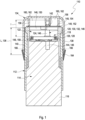
- FIG. 1 a cross-sectional view of an embodiment of a medical system 110 is shown.
- the medical system comprises a housing 112 which, as an example, may be made of a plastic material.
- the housing 112 may comprise one component or a plurality of components.
- an insertion actuator 114 is comprised, which, as an example, may comprise a pushbutton 116.
- a pushbutton 116 As an example for potential details of the insertion actuator, reference may be made to the above-mentioned prior art documents, such as to WO 2017/037191 A1 as well as the prior art cited therein. It shall be noted, however, that other insertion mechanisms are feasible.
- the housing 112 may comprise a receptacle 122 in which the preassembled functional module 118 is received.
- the preassembled functional module 118 comprises an analytical sensor 120 which is not visible in this figure and which is received within a sterility cap 124.
- the preassembled functional module 118 further comprises at least one electronics unit 126, such as at least one transmitter 128.
- the preassembled functional module 118 comprises at least one insertion component 130, which also is not visible in this figure.
- the insertion component 130 may comprise at least one insertion cannula 132, e.g. an insertion cannula 132 having a slot with the analytical sensor 120 received therein.
- the medical system 110 further comprises at least one protective cap 134.
- the protective cap 134 in the closed state as shown in Figure 1 , which is the state before use of the medical system 110, is connected to the housing 112.
- the protective cap 134 may overlap with the housing 112 in an overlap region 136.
- a circumferential rim 138 of the protective cap 134 may snugly fit on a circumferential guiding surface 140 on an upper outer side of the housing 112.
- the protective cap 134 for disconnecting from the housing 112, may be pulled off from the housing 112, wherein the guiding surface 140 may have a length L in the direction of pulling off the protective cap 134.
- the sterility cap 124 may be connected to the protective cap 134 by a connection 142.
- the sterility cap 124 may be pulled off from the insertion component 130.
- a length 1 of the sterility cap 124 may be smaller than the guiding length L, such that the sterility cap 124 fully clears the insertion component 130 before the guiding of the protective cap 134 by the guiding surface 140 ends.
- the sterility cap 124, the insertion component 130 and a holder 144 for the insertion component 130 may form a miniaturized sterile container 146 for the analytical sensor 120.
- This sterile container 146 may be disassembled, by removing the sterility cap 124, when the protective cap 134 is removed from the housing 112.
- the medical system 110 may further comprise a body mount 148.
- the body mount 148 which may also be placed in the receptacle 122, may contain a cradle 150 which may be placed against the skin of the user once the protective cap 134 is removed.
- the body mount 148 may further comprise an adhesive plaster 152 on top of the cradle 150, for adhering the cradle 150 onto the skin.
- the adhesive plaster 152 may be protected by a liner 154 which, e.g. via one or more protrusions 156 of the protective cap 134, may be connected to the protective cap 134.
- the protective cap 134 may also remove the liner 154 from the adhesive plaster 152.
- the cradle 150 may be configured for receiving the electronics unit 126.
- the electronics unit 126 may also fully or partially be part of the body mount 148.
- the electronics unit 126 in this exemplary embodiment, may be received in an upper shell 158, which may also form part of the body mount 148 and which may interact with the cradle 150 for providing a cover for the electronics unit 126.
- the medical system 110 may further comprise at least one desiccant 160.
- the desiccant 160 may be comprised in the protective cap 134, specifically in a plurality of chambers 162 provided by the protective cap 134.
- the medical system 110 may further comprise at least one indicator seal 164, such as at least one clearly visible tape, at a transition between the protective cap 134 and the housing 112.
- the indicator seal 164 firstly, may clearly indicate whether the medical system 110 has been used or not and may be broken when removing the protective cap 134 from the housing 112.
- the indicator seal 164 may provide further functionality, such as by providing a humidity barrier and by preventing or reducing the ingression of humidity into the protective cap 134 and/or into the housing 112. Further, the indicator seal 164 may provide a light barrier and may be rendered light-tight. This is specifically useful in connection with an optical switching mechanism.
- the electronics unit 126 may comprise an optical switch, such as an optical switch having a photodiode or a phototransistor.
- the protective cap 134 may be light-tight. When removing the protective cap 134 from the housing 112 for the first time, the photosensitive element of the electronics unit 126 may register the ambient light and may switch on the electronics unit 126. Other switches connected to the movement and removal of the protective cap 134 are feasible, such as mechanical switches.
- the electronics unit 126 may be configured for being switched on when the protective cap 134 is removed from the housing 112.
- At least one humidity seal 166 may be provided in between the protective cap 134 and the housing.
- one or more lines of glue may be provided on the guiding surface 140.
- the protective cap 134 may be removed from the housing 112.
- the sterility cap 124 may be removed from the insertion component 130.
- the removal of the sterility cap 124 may take place by purely translational movement, such as in an axial direction in Figure 1 .
- the removal of the sterility cap 124 may also imply a rotational movement, e.g. by transforming a translational movement of the protective cap 134 into a rotational movement of the sterility cap 124.
- a connection between the protective cap 134 and the sterility cap 124 may provide for an appropriate motion transformation, e.g. by providing one or more cams.
- the liner 154 may be removed, and the electronics unit 126 may be switched on. Subsequent to the removal of the protective cap 134, the housing 112 may be placed onto the desired skin side. Thereby, by the adhesive plaster 152, the cradle 150 is adhered to the skin.
- the insertion component 130 e.g. the insertion cannula 132
- the body mount 148 is assembled.
- the upper shell 158 is connected to the cradle 150, safely placing the electronics unit 126 in between.
- the electronics unit 126 may fully be designed as a disposable unit, without reusable parts.
- the switching mechanism e.g. triggered by the removal of the protective cap 134, the number of handling steps may significantly be reduced, leading to a simplified operating procedure which can be managed even by elderly people and children.
- the analytical sensor 120 and the electronics unit 126 may provide measurement values.
- the measurement values may be transmitted wirelessly to a receiver, such as a medical data management system.
Landscapes
- Health & Medical Sciences (AREA)
- Life Sciences & Earth Sciences (AREA)
- Physics & Mathematics (AREA)
- Surgery (AREA)
- General Health & Medical Sciences (AREA)
- Engineering & Computer Science (AREA)
- Biomedical Technology (AREA)
- Heart & Thoracic Surgery (AREA)
- Medical Informatics (AREA)
- Molecular Biology (AREA)
- Biophysics (AREA)
- Animal Behavior & Ethology (AREA)
- Pathology (AREA)
- Public Health (AREA)
- Veterinary Medicine (AREA)
- Optics & Photonics (AREA)
- Chemical & Material Sciences (AREA)
- Chemical Kinetics & Catalysis (AREA)
- General Chemical & Material Sciences (AREA)
- Emergency Medicine (AREA)
- Measurement Of The Respiration, Hearing Ability, Form, And Blood Characteristics Of Living Organisms (AREA)
- External Artificial Organs (AREA)
Priority Applications (4)
| Application Number | Priority Date | Filing Date | Title |
|---|---|---|---|
| SM20250055T SMT202500055T1 (it) | 2017-12-21 | 2018-12-20 | Sistema medico e procedimento di fabbricazione dello stesso |
| SI201831211T SI4241685T1 (sl) | 2017-12-21 | 2018-12-20 | Medicinski sistem in način njegove izdelave |
| RS20250201A RS66568B1 (sr) | 2017-12-21 | 2018-12-20 | Medicinski sistem i postupak za njegovu proizvodnju |
| HRP20250147TT HRP20250147T1 (hr) | 2017-12-21 | 2018-12-20 | Medicinski sustav i postupak za njegovu proizvodnju |
Applications Claiming Priority (4)
| Application Number | Priority Date | Filing Date | Title |
|---|---|---|---|
| EP17209756 | 2017-12-21 | ||
| EP21209045.0A EP3988014B1 (de) | 2017-12-21 | 2018-12-20 | Medizinisches system und verfahren zur herstellung davon |
| EP18826028.5A EP3727130B1 (de) | 2017-12-21 | 2018-12-20 | Medizinisches system und verfahren zur herstellung davon |
| PCT/EP2018/086139 WO2019122095A1 (en) | 2017-12-21 | 2018-12-20 | Medical system and method of manufacturing thereof |
Related Parent Applications (2)
| Application Number | Title | Priority Date | Filing Date |
|---|---|---|---|
| EP21209045.0A Division EP3988014B1 (de) | 2017-12-21 | 2018-12-20 | Medizinisches system und verfahren zur herstellung davon |
| EP18826028.5A Division EP3727130B1 (de) | 2017-12-21 | 2018-12-20 | Medizinisches system und verfahren zur herstellung davon |
Publications (3)
| Publication Number | Publication Date |
|---|---|
| EP4241685A2 true EP4241685A2 (de) | 2023-09-13 |
| EP4241685A3 EP4241685A3 (de) | 2023-10-25 |
| EP4241685B1 EP4241685B1 (de) | 2024-12-18 |
Family
ID=60781954
Family Applications (7)
| Application Number | Title | Priority Date | Filing Date |
|---|---|---|---|
| EP23169504.0A Active EP4241686B1 (de) | 2017-12-21 | 2018-12-20 | Medizinisches system und verfahren zur herstellung davon |
| EP21209045.0A Active EP3988014B1 (de) | 2017-12-21 | 2018-12-20 | Medizinisches system und verfahren zur herstellung davon |
| EP23169503.2A Active EP4241685B1 (de) | 2017-12-21 | 2018-12-20 | Medizinisches system und verfahren zur herstellung davon |
| EP23169501.6A Active EP4241684B1 (de) | 2017-12-21 | 2018-12-20 | Medizinisches system und verfahren zur herstellung davon |
| EP23169506.5A Active EP4238495B1 (de) | 2017-12-21 | 2018-12-20 | Medizinisches system und verfahren zur herstellung davon |
| EP24220147.3A Pending EP4537753A3 (de) | 2017-12-21 | 2018-12-20 | Medizinisches system und verfahren zu seiner herstellung |
| EP18826028.5A Active EP3727130B1 (de) | 2017-12-21 | 2018-12-20 | Medizinisches system und verfahren zur herstellung davon |
Family Applications Before (2)
| Application Number | Title | Priority Date | Filing Date |
|---|---|---|---|
| EP23169504.0A Active EP4241686B1 (de) | 2017-12-21 | 2018-12-20 | Medizinisches system und verfahren zur herstellung davon |
| EP21209045.0A Active EP3988014B1 (de) | 2017-12-21 | 2018-12-20 | Medizinisches system und verfahren zur herstellung davon |
Family Applications After (4)
| Application Number | Title | Priority Date | Filing Date |
|---|---|---|---|
| EP23169501.6A Active EP4241684B1 (de) | 2017-12-21 | 2018-12-20 | Medizinisches system und verfahren zur herstellung davon |
| EP23169506.5A Active EP4238495B1 (de) | 2017-12-21 | 2018-12-20 | Medizinisches system und verfahren zur herstellung davon |
| EP24220147.3A Pending EP4537753A3 (de) | 2017-12-21 | 2018-12-20 | Medizinisches system und verfahren zu seiner herstellung |
| EP18826028.5A Active EP3727130B1 (de) | 2017-12-21 | 2018-12-20 | Medizinisches system und verfahren zur herstellung davon |
Country Status (22)
| Country | Link |
|---|---|
| US (4) | US12064244B2 (de) |
| EP (7) | EP4241686B1 (de) |
| JP (2) | JP7139429B2 (de) |
| CN (2) | CN116509332B (de) |
| CA (1) | CA3085538C (de) |
| CY (2) | CY1125137T1 (de) |
| DE (5) | DE202018006849U1 (de) |
| DK (6) | DK4241686T3 (de) |
| ES (6) | ES2905955T3 (de) |
| FI (5) | FI4238495T3 (de) |
| HR (5) | HRP20230596T1 (de) |
| HU (6) | HUE070427T2 (de) |
| IL (1) | IL275385B2 (de) |
| LT (5) | LT4241685T (de) |
| PL (6) | PL4241684T3 (de) |
| PT (6) | PT4241684T (de) |
| RS (5) | RS66567B1 (de) |
| RU (1) | RU2755245C1 (de) |
| SI (5) | SI3988014T1 (de) |
| SM (5) | SMT202500061T1 (de) |
| WO (1) | WO2019122095A1 (de) |
| ZA (1) | ZA202002998B (de) |
Families Citing this family (12)
| Publication number | Priority date | Publication date | Assignee | Title |
|---|---|---|---|---|
| CN119924827A (zh) | 2018-06-07 | 2025-05-06 | 雅培糖尿病护理公司 | 用于分析物监测系统的聚焦灭菌和已灭菌的子组件 |
| EP3871602B1 (de) | 2020-02-26 | 2023-09-27 | Roche Diabetes Care GmbH | Medizinisches system und verfahren zur sterilitätsprüfung des medizinischen systems |
| CN115988988A (zh) | 2020-08-26 | 2023-04-18 | 丁格医疗有限责任公司 | 葡萄糖感测的系统、装置和方法以及相关方法的有关应用 |
| EP3960079A1 (de) | 2020-08-31 | 2022-03-02 | Roche Diabetes Care GmbH | Vorrichtung zum einsetzen einer medizinischen vorrichtung in ein körpergewebe |
| WO2022049229A1 (en) * | 2020-09-07 | 2022-03-10 | Ascensia Diabetes Care Holdings Ag | Methods and apparatus enabling coupling of an electronics unit to a base unit of a continuous analyte monitoring device |
| TWD231831S (zh) * | 2023-03-15 | 2024-06-21 | 華廣生技股份有限公司 臺中市南區大慶街2段100號 (中華民國) | 用於生理監測裝置的拆分器之部分 |
| WO2024218057A1 (en) | 2023-04-19 | 2024-10-24 | F. Hoffmann-La Roche Ag | Insertion device |
| CN121908987A (zh) | 2023-09-26 | 2026-04-21 | 罗氏糖尿病护理有限责任公司 | 用于检测体液中的分析物的医疗装置 |
| GB2634100A (en) * | 2023-09-29 | 2025-04-02 | Glucorx Tech Limited | Analyte sensor applicator |
| WO2025132157A1 (en) | 2023-12-20 | 2025-06-26 | Roche Diabetes Care Gmbh | Continuous analyte monitoring device |
| WO2025149300A1 (en) | 2024-01-10 | 2025-07-17 | Roche Diabetes Care Gmbh | Continuous analyte monitoring unit |
| WO2025162779A1 (en) | 2024-01-31 | 2025-08-07 | Roche Diabetes Care Gmbh | Continuous analyte monitoring device |
Citations (10)
| Publication number | Priority date | Publication date | Assignee | Title |
|---|---|---|---|---|
| US20070202488A1 (en) | 2004-02-26 | 2007-08-30 | Hendrix Stephen W | Methods for determining the relative benefits and/or evaluating quantitative changes of products on epithelial tissue |
| US20100200538A1 (en) | 2009-02-09 | 2010-08-12 | Edwards Lifesciences Corporation | Analyte Sensor and Fabrication Methods |
| US20100286714A1 (en) | 2007-07-18 | 2010-11-11 | Steffen Gyrn | Inserter device with controlled acceleration |
| WO2011119896A1 (en) | 2010-03-24 | 2011-09-29 | Abbott Diabetes Care Inc. | Medical device inserters and processes of inserting and using medical devices |
| EP2348964B1 (de) | 2008-09-11 | 2013-05-15 | Roche Diagnostics GmbH | Elektrodensystem zur messung einer analytenkonzentration unter in-vivo-bedingungen |
| WO2016012497A1 (en) | 2014-07-22 | 2016-01-28 | Roche Diagnostics Gmbh | Insertion device with safety lock |
| WO2016012482A1 (en) | 2014-07-22 | 2016-01-28 | Roche Diagnostics Gmbh | Insertion device with protection against reuse |
| EP2991552A1 (de) | 2013-04-30 | 2016-03-09 | Abbott Diabetes Care Inc. | Systeme, vorrichtungen und verfahren für energieeffiziente aktivierung einer elektrischen vorrichtung |
| US20160331284A1 (en) | 2015-05-14 | 2016-11-17 | Abbott Diabetes Care Inc. | Compact medical device inserters and related systems and methods |
| WO2017037191A1 (en) | 2015-09-02 | 2017-03-09 | Roche Diabetes Care Gmbh | Kit for determining an analyte concentration |
Family Cites Families (84)
| Publication number | Priority date | Publication date | Assignee | Title |
|---|---|---|---|---|
| DE954712C (de) | 1953-03-22 | 1956-12-20 | Licentia Gmbh | Schaltelement zur Betaetigung mehrerer Kontakte |
| US5638818A (en) | 1991-03-21 | 1997-06-17 | Masimo Corporation | Low noise optical probe |
| US5413690A (en) | 1993-07-23 | 1995-05-09 | Boehringer Mannheim Corporation | Potentiometric biosensor and the method of its use |
| US5762770A (en) | 1994-02-21 | 1998-06-09 | Boehringer Mannheim Corporation | Electrochemical biosensor test strip |
| US5798031A (en) | 1997-05-12 | 1998-08-25 | Bayer Corporation | Electrochemical biosensor |
| US6129823A (en) | 1997-09-05 | 2000-10-10 | Abbott Laboratories | Low volume electrochemical sensor |
| US6360888B1 (en) | 1999-02-25 | 2002-03-26 | Minimed Inc. | Glucose sensor package system |
| US20010030511A1 (en) | 2000-04-18 | 2001-10-18 | Shunpei Yamazaki | Display device |
| DE20020566U1 (de) | 2000-12-04 | 2002-01-24 | Filtec Filtertechnologie für die Elektronikindustrie GmbH, 59557 Lippstadt | Mehrpoliger Steckverbinder |
| IL157916A0 (en) | 2001-03-14 | 2004-03-28 | Tyco Healthcare | Safety shield for medical needles |
| US6923936B2 (en) | 2001-10-23 | 2005-08-02 | Medtronic Minimed, Inc. | Sterile device and method for producing same |
| JP2004049607A (ja) | 2002-07-22 | 2004-02-19 | Enomoto Co Ltd | 留置針及び採血用器具 |
| US7381184B2 (en) | 2002-11-05 | 2008-06-03 | Abbott Diabetes Care Inc. | Sensor inserter assembly |
| JP4398647B2 (ja) | 2003-01-28 | 2010-01-13 | テルモ株式会社 | 成分測定用穿刺具とその製造方法 |
| EP1475113A1 (de) | 2003-05-08 | 2004-11-10 | Novo Nordisk A/S | Externer Nadeleinsetzer |
| JP2007524816A (ja) | 2003-06-20 | 2007-08-30 | エフ ホフマン−ラ ロッシュ アクチェン ゲゼルシャフト | 細い均一な試薬ストリップの製造方法およびその試薬 |
| US20140121989A1 (en) * | 2003-08-22 | 2014-05-01 | Dexcom, Inc. | Systems and methods for processing analyte sensor data |
| GB0324450D0 (en) | 2003-10-20 | 2003-11-19 | Alertis Medical As | Sensor |
| US7699807B2 (en) | 2003-11-10 | 2010-04-20 | Smiths Medical Asd, Inc. | Device and method for insertion of a cannula of an infusion device |
| ATE408370T1 (de) | 2003-12-22 | 2008-10-15 | Paul Hadvary | Dermal befestigte sensorvorrichtung |
| US7585287B2 (en) | 2004-06-16 | 2009-09-08 | Smiths Medical Md, Inc. | Device and method for insertion of a cannula of an infusion device |
| US8989833B2 (en) | 2004-07-13 | 2015-03-24 | Dexcom, Inc. | Transcutaneous analyte sensor |
| EP1781164A1 (de) | 2004-08-10 | 2007-05-09 | Novo Nordisk A/S | Verfahren zur bildung einer sterilisierten sensorpackung und sterilisierte sensorpackung |
| CA2590559C (en) | 2004-12-13 | 2011-06-14 | Bayer Healthcare Llc | Sensor-dispensing instruments |
| US10226207B2 (en) * | 2004-12-29 | 2019-03-12 | Abbott Diabetes Care Inc. | Sensor inserter having introducer |
| US20090105569A1 (en) | 2006-04-28 | 2009-04-23 | Abbott Diabetes Care, Inc. | Introducer Assembly and Methods of Use |
| US8333714B2 (en) | 2006-09-10 | 2012-12-18 | Abbott Diabetes Care Inc. | Method and system for providing an integrated analyte sensor insertion device and data processing unit |
| US9259175B2 (en) | 2006-10-23 | 2016-02-16 | Abbott Diabetes Care, Inc. | Flexible patch for fluid delivery and monitoring body analytes |
| DE502005002216D1 (de) | 2005-04-08 | 2008-01-24 | Roche Diagnostics Gmbh | Vorrichtung zur Platzierung einer Sonde in lebendem Gewebe |
| US9072476B2 (en) | 2005-09-23 | 2015-07-07 | Medtronic Minimed, Inc. | Flexible sensor apparatus |
| US7638095B2 (en) | 2006-02-10 | 2009-12-29 | Roche Diagnostics Operations, Inc. | Personal portable blood glucose meter with replaceable cartridge of test strips |
| ITFI20060310A1 (it) * | 2006-12-07 | 2008-06-08 | Menarini Farma Ind | Dispositivo portatile per la misura ed il controllo di analiti in fluidi biologici. |
| EP1972267A1 (de) | 2007-03-20 | 2008-09-24 | Roche Diagnostics GmbH | System zur in-vivo Messung einer Analytkonzentration |
| SI1972275T1 (sl) | 2007-03-20 | 2016-02-29 | F. Hoffmann-La Roche Ag | Sistem za merjenje koncentracije analita in vivo |
| WO2009126900A1 (en) | 2008-04-11 | 2009-10-15 | Pelikan Technologies, Inc. | Method and apparatus for analyte detecting device |
| JP5743900B2 (ja) | 2008-12-15 | 2015-07-01 | ノボ・ノルデイスク・エー/エス | 傾斜可能な安全注射針 |
| US20100198034A1 (en) | 2009-02-03 | 2010-08-05 | Abbott Diabetes Care Inc. | Compact On-Body Physiological Monitoring Devices and Methods Thereof |
| CN101596104A (zh) | 2009-06-11 | 2009-12-09 | 浙江大学 | 慢性病社区防治的无线反馈控制系统与方法 |
| US20100331738A1 (en) | 2009-06-30 | 2010-12-30 | Orthosensor | Integrated sensor and interconnect for measuring a parameter of the muscular-skeletal system |
| JP5624984B2 (ja) * | 2009-06-30 | 2014-11-12 | アークレイ株式会社 | 連続分析装置 |
| CN102549115B (zh) | 2009-07-29 | 2014-12-10 | 詹姆斯·马修·梅森 | 用于下吸式气化的系统和方法 |
| RU2509532C2 (ru) | 2009-09-24 | 2014-03-20 | АРКРЭЙ, Инк. | Измерительное устройство и способ измерения |
| EP2503959A4 (de) | 2009-11-25 | 2014-07-09 | Univ Drexel | In einem hybridverfahren hergestellter gefässpfropf von geringem durchmesser |
| DK2506914T3 (en) | 2009-11-30 | 2018-12-10 | Hoffmann La Roche | ANALYSIS MONITORING AND FLUID SUBMISSION SYSTEM |
| US20120259192A1 (en) | 2009-12-24 | 2012-10-11 | Arkray, Inc. | Measuring apparatus and sensor placement method |
| MX2012011085A (es) | 2010-03-30 | 2012-10-10 | Unomedical As | Dispositivo medico. |
| EP2422693B1 (de) | 2010-08-27 | 2018-11-28 | Roche Diabetes Care GmbH | Vorrichtung und Verfahren zur Durchführung mindestens einer medizinischen Funktion |
| JP5748595B2 (ja) | 2010-08-30 | 2015-07-15 | アークレイ株式会社 | センサ挿入・回収装置 |
| EP2621333B1 (de) | 2010-09-28 | 2015-07-29 | Masimo Corporation | Bewusstseinstiefenmonitor mit oximeter |
| FI3300658T3 (fi) | 2011-12-11 | 2024-03-01 | Abbott Diabetes Care Inc | Analyyttianturimenetelmiä |
| CN103156619A (zh) | 2011-12-12 | 2013-06-19 | 深圳市泰嘉电子有限公司 | 硅胶指夹式血氧饱和度传感器 |
| US9610401B2 (en) | 2012-01-13 | 2017-04-04 | Medtronic Minimed, Inc. | Infusion set component with modular fluid channel element |
| RU2611038C2 (ru) * | 2012-03-27 | 2017-02-20 | Ф.Хоффманн-Ля Рош Аг | Улучшенная спейсерная мембрана для ферментного датчика in vivo |
| US9931065B2 (en) | 2012-04-04 | 2018-04-03 | Dexcom, Inc. | Transcutaneous analyte sensors, applicators therefor, and associated methods |
| US9493807B2 (en) | 2012-05-25 | 2016-11-15 | Medtronic Minimed, Inc. | Foldover sensors and methods for making and using them |
| EP2668901A1 (de) | 2012-05-31 | 2013-12-04 | Roche Diagniostics GmbH | Sensoreinführanordnung, Sensorpatrone und Inserter |
| RU2616131C2 (ru) | 2012-07-05 | 2017-04-12 | Микротек Медикал Текнолоджис Лтд. | Система и способ прямого введения устройства для контроля физиологических условий |
| US20150173661A1 (en) | 2012-07-27 | 2015-06-25 | Abbott Diabetes Care, Inc. | Medical Device Applicators |
| WO2014018069A1 (en) * | 2012-07-27 | 2014-01-30 | Bayer Healthcare Llc | System and method for detecting used and dried sensors |
| US8888709B2 (en) | 2012-09-12 | 2014-11-18 | Boston Scientific Scimed, Inc. | Method and apparatus for sensing and avoiding cardiac conduction system during valve deployment |
| JP6182155B2 (ja) | 2012-12-12 | 2017-08-16 | パナソニックヘルスケアホールディングス株式会社 | 血液成分の測定装置、血液成分の測定方法、及び、バイオセンサ |
| JP6166904B2 (ja) | 2013-01-25 | 2017-07-19 | テルモ株式会社 | 血糖計 |
| US10357191B2 (en) | 2013-03-14 | 2019-07-23 | Becton, Dickinson And Company | Continuous glucose monitoring on-body sensor |
| RU133942U1 (ru) * | 2013-06-19 | 2013-10-27 | Общество с ограниченной ответственностью "Научно-производственная фирма "ЛАБОВЭЙ" | Биосенсор-картридж для анализатора глюкозы с термокомпенсацией |
| EP2982303B1 (de) | 2014-08-06 | 2017-02-22 | Roche Diabetes Care GmbH | Medizinische Vorrichtung und Verfahren zur Herstellung einer medizinischen Vorrichtung |
| US10194843B2 (en) | 2014-09-03 | 2019-02-05 | Nova Biomedical Corporation | Subcutaneous sensor inserter and method |
| ES2894735T3 (es) | 2014-10-27 | 2022-02-15 | Glutalor Medical Inc | Aparatos de recolección continua de glucosa |
| CN204233137U (zh) | 2014-11-05 | 2015-04-01 | 深圳市光聚通讯技术开发有限公司 | 动态血糖仪探针植入定位结构 |
| CN204233136U (zh) | 2014-11-12 | 2015-04-01 | 深圳市光聚通讯技术开发有限公司 | 动态血糖监测仪探针 |
| US10213139B2 (en) | 2015-05-14 | 2019-02-26 | Abbott Diabetes Care Inc. | Systems, devices, and methods for assembling an applicator and sensor control device |
| US10105100B2 (en) | 2015-07-28 | 2018-10-23 | Verily Life Sciences Llc | Display on a bandage-type monitoring device |
| CN105534508A (zh) | 2015-12-17 | 2016-05-04 | 季婷婷 | 一种智能护理机 |
| ES2976108T3 (es) | 2015-12-30 | 2024-07-23 | Dexcom Inc | Sistemas y métodos de sensor de analito transcutáneo |
| DE202016009189U1 (de) | 2016-02-05 | 2023-08-25 | Roche Diabetes Care Gmbh | Medizinische Vorrichtung zum Nachweis mindestens eines Analyten in einer Körperflüssigkeit |
| LT4233720T (lt) | 2016-02-05 | 2024-09-25 | F. Hoffmann-La Roche Ag | Medicinos prietaisas, skirtas bent vienai medžiagai kūno skystyje aptikti |
| EP4491116A3 (de) * | 2016-02-05 | 2025-03-19 | Roche Diabetes Care GmbH | Medizinische vorrichtung zum nachweis von mindestens einem analyten in einer körperflüssigkeit |
| CH712753A2 (de) * | 2016-07-28 | 2018-01-31 | Tecpharma Licensing Ag | Trennen einer Nadelschutzkappe von einem Produktbehälter und Verfahren zum Montieren einer Injektionsvorrichtung. |
| EP3278729B1 (de) * | 2016-08-04 | 2020-06-24 | Roche Diabetes Care GmbH | Medizinische vorrichtung zur detektion von mindestens einem analyten in einer körperflüssigkeit |
| JP2020517333A (ja) | 2017-04-19 | 2020-06-18 | メトロノーム・ヘルス、インコーポレイテッド | 検体センサの挿入器 |
| CN110612061A (zh) | 2017-05-09 | 2019-12-24 | 安晟信医疗科技控股公司 | 用于连续葡萄糖监测器的传感器组件装置和方法 |
| EP3406193B1 (de) | 2017-05-23 | 2021-12-08 | Roche Diabetes Care GmbH | Sensorsystem und verfahren zur herstellung davon |
| KR102164781B1 (ko) | 2017-06-02 | 2020-10-15 | 주식회사 아이센스 | 연속 혈당 측정기용 센서 어플리케이터 조립체 |
| WO2018222010A1 (ko) | 2017-06-02 | 2018-12-06 | 주식회사 아이센스 | 연속 혈당 측정기용 센서 어플리케이터 조립체 |
| CN111093472A (zh) * | 2017-06-19 | 2020-05-01 | 德克斯康公司 | 施加经皮分析物传感器的施加器和相关制造方法 |
-
2018
- 2018-12-20 PT PT231695016T patent/PT4241684T/pt unknown
- 2018-12-20 HU HUE23169506A patent/HUE070427T2/hu unknown
- 2018-12-20 RU RU2020123105A patent/RU2755245C1/ru active
- 2018-12-20 JP JP2020534504A patent/JP7139429B2/ja active Active
- 2018-12-20 LT LTEP23169503.2T patent/LT4241685T/lt unknown
- 2018-12-20 RS RS20250200A patent/RS66567B1/sr unknown
- 2018-12-20 SM SM20250061T patent/SMT202500061T1/it unknown
- 2018-12-20 PT PT231695065T patent/PT4238495T/pt unknown
- 2018-12-20 PL PL23169501.6T patent/PL4241684T3/pl unknown
- 2018-12-20 ES ES18826028T patent/ES2905955T3/es active Active
- 2018-12-20 EP EP23169504.0A patent/EP4241686B1/de active Active
- 2018-12-20 DK DK23169504.0T patent/DK4241686T3/da active
- 2018-12-20 HR HRP20230596TT patent/HRP20230596T1/hr unknown
- 2018-12-20 FI FIEP23169506.5T patent/FI4238495T3/fi active
- 2018-12-20 SM SM20250060T patent/SMT202500060T1/it unknown
- 2018-12-20 SM SM20230181T patent/SMT202300181T1/it unknown
- 2018-12-20 HR HRP20250151TT patent/HRP20250151T1/hr unknown
- 2018-12-20 CN CN202310495763.7A patent/CN116509332B/zh active Active
- 2018-12-20 PT PT212090450T patent/PT3988014T/pt unknown
- 2018-12-20 SI SI201830932T patent/SI3988014T1/sl unknown
- 2018-12-20 ES ES23169506T patent/ES3011508T3/es active Active
- 2018-12-20 SM SM20250057T patent/SMT202500057T1/it unknown
- 2018-12-20 PL PL23169503.2T patent/PL4241685T3/pl unknown
- 2018-12-20 DK DK21209045.0T patent/DK3988014T3/da active
- 2018-12-20 LT LTEP21209045.0T patent/LT3988014T/lt unknown
- 2018-12-20 HU HUE23169501A patent/HUE070428T2/hu unknown
- 2018-12-20 HR HRP20250147TT patent/HRP20250147T1/hr unknown
- 2018-12-20 CN CN201880082537.3A patent/CN111491554B/zh active Active
- 2018-12-20 HR HRP20250138TT patent/HRP20250138T1/hr unknown
- 2018-12-20 PL PL23169506.5T patent/PL4238495T3/pl unknown
- 2018-12-20 LT LTEP23169506.5T patent/LT4238495T/lt unknown
- 2018-12-20 EP EP21209045.0A patent/EP3988014B1/de active Active
- 2018-12-20 SI SI201831209T patent/SI4241684T1/sl unknown
- 2018-12-20 DK DK18826028.5T patent/DK3727130T3/da active
- 2018-12-20 FI FIEP23169501.6T patent/FI4241684T3/fi active
- 2018-12-20 CA CA3085538A patent/CA3085538C/en active Active
- 2018-12-20 EP EP23169503.2A patent/EP4241685B1/de active Active
- 2018-12-20 DE DE202018006849.7U patent/DE202018006849U1/de active Active
- 2018-12-20 RS RS20250202A patent/RS66569B1/sr unknown
- 2018-12-20 HR HRP20250150TT patent/HRP20250150T1/hr unknown
- 2018-12-20 HU HUE23169504A patent/HUE070422T2/hu unknown
- 2018-12-20 FI FIEP21209045.0T patent/FI3988014T3/fi active
- 2018-12-20 DE DE202018006848.9U patent/DE202018006848U1/de active Active
- 2018-12-20 DK DK23169501.6T patent/DK4241684T3/da active
- 2018-12-20 SI SI201831212T patent/SI4241686T1/sl unknown
- 2018-12-20 PL PL21209045.0T patent/PL3988014T3/pl unknown
- 2018-12-20 PT PT231695032T patent/PT4241685T/pt unknown
- 2018-12-20 RS RS20250203A patent/RS66570B1/sr unknown
- 2018-12-20 FI FIEP23169504.0T patent/FI4241686T3/fi active
- 2018-12-20 DK DK23169503.2T patent/DK4241685T3/da active
- 2018-12-20 PL PL23169504.0T patent/PL4241686T3/pl unknown
- 2018-12-20 ES ES23169503T patent/ES3010391T3/es active Active
- 2018-12-20 IL IL275385A patent/IL275385B2/en unknown
- 2018-12-20 ES ES23169504T patent/ES3009418T3/es active Active
- 2018-12-20 SM SM20250055T patent/SMT202500055T1/it unknown
- 2018-12-20 HU HUE23169503A patent/HUE070431T2/hu unknown
- 2018-12-20 HU HUE21209045A patent/HUE062116T2/hu unknown
- 2018-12-20 DE DE202018006851.9U patent/DE202018006851U1/de active Active
- 2018-12-20 EP EP23169501.6A patent/EP4241684B1/de active Active
- 2018-12-20 RS RS20230428A patent/RS64267B1/sr unknown
- 2018-12-20 HU HUE18826028A patent/HUE057393T2/hu unknown
- 2018-12-20 DK DK23169506.5T patent/DK4238495T3/da active
- 2018-12-20 FI FIEP23169503.2T patent/FI4241685T3/fi active
- 2018-12-20 PT PT231695040T patent/PT4241686T/pt unknown
- 2018-12-20 EP EP23169506.5A patent/EP4238495B1/de active Active
- 2018-12-20 DE DE202018006850.0U patent/DE202018006850U1/de active Active
- 2018-12-20 PT PT188260285T patent/PT3727130T/pt unknown
- 2018-12-20 LT LTEP23169501.6T patent/LT4241684T/lt unknown
- 2018-12-20 RS RS20250201A patent/RS66568B1/sr unknown
- 2018-12-20 ES ES23169501T patent/ES3010633T3/es active Active
- 2018-12-20 ES ES21209045T patent/ES2947498T3/es active Active
- 2018-12-20 EP EP24220147.3A patent/EP4537753A3/de active Pending
- 2018-12-20 PL PL18826028T patent/PL3727130T3/pl unknown
- 2018-12-20 SI SI201831211T patent/SI4241685T1/sl unknown
- 2018-12-20 EP EP18826028.5A patent/EP3727130B1/de active Active
- 2018-12-20 WO PCT/EP2018/086139 patent/WO2019122095A1/en not_active Ceased
- 2018-12-20 DE DE202018006862.4U patent/DE202018006862U1/de active Active
- 2018-12-20 SI SI201831210T patent/SI4238495T1/sl unknown
- 2018-12-20 LT LTEP23169504.0T patent/LT4241686T/lt unknown
-
2020
- 2020-05-21 ZA ZA2020/02998A patent/ZA202002998B/en unknown
- 2020-06-10 US US16/898,049 patent/US12064244B2/en active Active
-
2022
- 2022-02-07 CY CY20221100103T patent/CY1125137T1/el unknown
- 2022-09-07 JP JP2022142550A patent/JP7477570B2/ja active Active
-
2023
- 2023-06-16 CY CY20231100284T patent/CY1126043T1/el unknown
- 2023-08-04 US US18/365,778 patent/US12082928B2/en active Active
- 2023-08-04 US US18/365,822 patent/US12064245B2/en active Active
-
2024
- 2024-07-16 US US18/774,381 patent/US20240366128A1/en active Pending
Patent Citations (10)
| Publication number | Priority date | Publication date | Assignee | Title |
|---|---|---|---|---|
| US20070202488A1 (en) | 2004-02-26 | 2007-08-30 | Hendrix Stephen W | Methods for determining the relative benefits and/or evaluating quantitative changes of products on epithelial tissue |
| US20100286714A1 (en) | 2007-07-18 | 2010-11-11 | Steffen Gyrn | Inserter device with controlled acceleration |
| EP2348964B1 (de) | 2008-09-11 | 2013-05-15 | Roche Diagnostics GmbH | Elektrodensystem zur messung einer analytenkonzentration unter in-vivo-bedingungen |
| US20100200538A1 (en) | 2009-02-09 | 2010-08-12 | Edwards Lifesciences Corporation | Analyte Sensor and Fabrication Methods |
| WO2011119896A1 (en) | 2010-03-24 | 2011-09-29 | Abbott Diabetes Care Inc. | Medical device inserters and processes of inserting and using medical devices |
| EP2991552A1 (de) | 2013-04-30 | 2016-03-09 | Abbott Diabetes Care Inc. | Systeme, vorrichtungen und verfahren für energieeffiziente aktivierung einer elektrischen vorrichtung |
| WO2016012497A1 (en) | 2014-07-22 | 2016-01-28 | Roche Diagnostics Gmbh | Insertion device with safety lock |
| WO2016012482A1 (en) | 2014-07-22 | 2016-01-28 | Roche Diagnostics Gmbh | Insertion device with protection against reuse |
| US20160331284A1 (en) | 2015-05-14 | 2016-11-17 | Abbott Diabetes Care Inc. | Compact medical device inserters and related systems and methods |
| WO2017037191A1 (en) | 2015-09-02 | 2017-03-09 | Roche Diabetes Care Gmbh | Kit for determining an analyte concentration |
Also Published As
Similar Documents
| Publication | Publication Date | Title |
|---|---|---|
| US12082928B2 (en) | Medical system and method of manufacturing thereof | |
| EP3202324B1 (de) | Medizinische vorrichtung zur detektion von mindestens einem analyten in einer körperflüssigkeit | |
| HK40035112A (en) | Medical system and method of manufacturing thereof | |
| BR112020010749B1 (pt) | Sistema médico e método para a fabricação de um sistema médico |
Legal Events
| Date | Code | Title | Description |
|---|---|---|---|
| REG | Reference to a national code |
Ref country code: HR Ref legal event code: TUEP Ref document number: P20250147T Country of ref document: HR |
|
| PUAI | Public reference made under article 153(3) epc to a published international application that has entered the european phase |
Free format text: ORIGINAL CODE: 0009012 |
|
| STAA | Information on the status of an ep patent application or granted ep patent |
Free format text: STATUS: THE APPLICATION HAS BEEN PUBLISHED |
|
| AC | Divisional application: reference to earlier application |
Ref document number: 3727130 Country of ref document: EP Kind code of ref document: P Ref document number: 3988014 Country of ref document: EP Kind code of ref document: P |
|
| AK | Designated contracting states |
Kind code of ref document: A2 Designated state(s): AL AT BE BG CH CY CZ DE DK EE ES FI FR GB GR HR HU IE IS IT LI LT LU LV MC MK MT NL NO PL PT RO RS SE SI SK SM TR |
|
| REG | Reference to a national code |
Ref country code: DE Ref legal event code: R079 Free format text: PREVIOUS MAIN CLASS: A61B0005148600 Ipc: A61B0005000000 Ref document number: 602018077867 Country of ref document: DE |
|
| PUAL | Search report despatched |
Free format text: ORIGINAL CODE: 0009013 |
|
| AK | Designated contracting states |
Kind code of ref document: A3 Designated state(s): AL AT BE BG CH CY CZ DE DK EE ES FI FR GB GR HR HU IE IS IT LI LT LU LV MC MK MT NL NO PL PT RO RS SE SI SK SM TR |
|
| RIC1 | Information provided on ipc code assigned before grant |
Ipc: A61B 5/1486 20060101ALI20230921BHEP Ipc: A61B 5/145 20060101ALI20230921BHEP Ipc: A61B 5/00 20060101AFI20230921BHEP |
|
| STAA | Information on the status of an ep patent application or granted ep patent |
Free format text: STATUS: REQUEST FOR EXAMINATION WAS MADE |
|
| 17P | Request for examination filed |
Effective date: 20231221 |
|
| RBV | Designated contracting states (corrected) |
Designated state(s): AL AT BE BG CH CY CZ DE DK EE ES FI FR GB GR HR HU IE IS IT LI LT LU LV MC MK MT NL NO PL PT RO RS SE SI SK SM TR |
|
| GRAP | Despatch of communication of intention to grant a patent |
Free format text: ORIGINAL CODE: EPIDOSNIGR1 |
|
| STAA | Information on the status of an ep patent application or granted ep patent |
Free format text: STATUS: GRANT OF PATENT IS INTENDED |
|
| INTG | Intention to grant announced |
Effective date: 20240228 |
|
| GRAJ | Information related to disapproval of communication of intention to grant by the applicant or resumption of examination proceedings by the epo deleted |
Free format text: ORIGINAL CODE: EPIDOSDIGR1 |
|
| STAA | Information on the status of an ep patent application or granted ep patent |
Free format text: STATUS: REQUEST FOR EXAMINATION WAS MADE |
|
| GRAP | Despatch of communication of intention to grant a patent |
Free format text: ORIGINAL CODE: EPIDOSNIGR1 |
|
| INTC | Intention to grant announced (deleted) | ||
| STAA | Information on the status of an ep patent application or granted ep patent |
Free format text: STATUS: GRANT OF PATENT IS INTENDED |
|
| INTG | Intention to grant announced |
Effective date: 20240718 |
|
| GRAS | Grant fee paid |
Free format text: ORIGINAL CODE: EPIDOSNIGR3 |
|
| GRAA | (expected) grant |
Free format text: ORIGINAL CODE: 0009210 |
|
| STAA | Information on the status of an ep patent application or granted ep patent |
Free format text: STATUS: THE PATENT HAS BEEN GRANTED |
|
| P01 | Opt-out of the competence of the unified patent court (upc) registered |
Free format text: CASE NUMBER: APP_59943/2024 Effective date: 20241106 |
|
| AC | Divisional application: reference to earlier application |
Ref document number: 3727130 Country of ref document: EP Kind code of ref document: P Ref document number: 3988014 Country of ref document: EP Kind code of ref document: P |
|
| AK | Designated contracting states |
Kind code of ref document: B1 Designated state(s): AL AT BE BG CH CY CZ DE DK EE ES FI FR GB GR HR HU IE IS IT LI LT LU LV MC MK MT NL NO PL PT RO RS SE SI SK SM TR |
|
| REG | Reference to a national code |
Ref country code: CH Ref legal event code: EP |
|
| REG | Reference to a national code |
Ref country code: DE Ref legal event code: R096 Ref document number: 602018077867 Country of ref document: DE |
|
| REG | Reference to a national code |
Ref country code: IE Ref legal event code: FG4D |
|
| REG | Reference to a national code |
Ref country code: PT Ref legal event code: SC4A Ref document number: 4241685 Country of ref document: PT Date of ref document: 20250205 Kind code of ref document: T Free format text: AVAILABILITY OF NATIONAL TRANSLATION Effective date: 20250130 |
|
| REG | Reference to a national code |
Ref country code: DK Ref legal event code: T3 Effective date: 20250217 |
|
| REG | Reference to a national code |
Ref country code: FI Ref legal event code: FGE |
|
| REG | Reference to a national code |
Ref country code: NL Ref legal event code: FP |
|
| REG | Reference to a national code |
Ref country code: SE Ref legal event code: TRGR |
|
| REG | Reference to a national code |
Ref country code: GR Ref legal event code: EP Ref document number: 20250400308 Country of ref document: GR Effective date: 20250314 |
|
| REG | Reference to a national code |
Ref country code: SK Ref legal event code: T3 Ref document number: E 45884 Country of ref document: SK |
|
| REG | Reference to a national code |
Ref country code: HR Ref legal event code: T1PR Ref document number: P20250147 Country of ref document: HR Ref country code: HR Ref legal event code: ODRP Ref document number: P20250147 Country of ref document: HR Payment date: 20250212 Year of fee payment: 7 |
|
| REG | Reference to a national code |
Ref country code: ES Ref legal event code: FG2A Ref document number: 3010391 Country of ref document: ES Kind code of ref document: T3 Effective date: 20250402 |
|
| REG | Reference to a national code |
Ref country code: EE Ref legal event code: FG4A Ref document number: E024891 Country of ref document: EE Effective date: 20250129 |
|
| PGFP | Annual fee paid to national office [announced via postgrant information from national office to epo] |
Ref country code: CH Payment date: 20250121 Year of fee payment: 7 |
|
| REG | Reference to a national code |
Ref country code: HU Ref legal event code: AG4A Ref document number: E070431 Country of ref document: HU |
|
| REG | Reference to a national code |
Ref country code: DE Ref legal event code: R097 Ref document number: 602018077867 Country of ref document: DE |
|
| PLBE | No opposition filed within time limit |
Free format text: ORIGINAL CODE: 0009261 |
|
| STAA | Information on the status of an ep patent application or granted ep patent |
Free format text: STATUS: NO OPPOSITION FILED WITHIN TIME LIMIT |
|
| REG | Reference to a national code |
Ref country code: CH Ref legal event code: L10 Free format text: ST27 STATUS EVENT CODE: U-0-0-L10-L00 (AS PROVIDED BY THE NATIONAL OFFICE) Effective date: 20251029 |
|
| 26N | No opposition filed |
Effective date: 20250919 |
|
| PGFP | Annual fee paid to national office [announced via postgrant information from national office to epo] |
Ref country code: PT Payment date: 20251121 Year of fee payment: 8 |
|
| PGFP | Annual fee paid to national office [announced via postgrant information from national office to epo] |
Ref country code: LU Payment date: 20251119 Year of fee payment: 8 Ref country code: NL Payment date: 20251119 Year of fee payment: 8 |
|
| REG | Reference to a national code |
Ref country code: CH Ref legal event code: U11 Free format text: ST27 STATUS EVENT CODE: U-0-0-U10-U11 (AS PROVIDED BY THE NATIONAL OFFICE) Effective date: 20260101 |
|
| REG | Reference to a national code |
Ref country code: HR Ref legal event code: ODRP Ref document number: P20250147 Country of ref document: HR Payment date: 20251202 Year of fee payment: 8 |
|
| PGFP | Annual fee paid to national office [announced via postgrant information from national office to epo] |
Ref country code: IS Payment date: 20251215 Year of fee payment: 8 Ref country code: DE Payment date: 20251126 Year of fee payment: 8 |
|
| PGFP | Annual fee paid to national office [announced via postgrant information from national office to epo] |
Ref country code: LT Payment date: 20251119 Year of fee payment: 8 Ref country code: GB Payment date: 20251119 Year of fee payment: 8 |
|
| PGFP | Annual fee paid to national office [announced via postgrant information from national office to epo] |
Ref country code: MC Payment date: 20251124 Year of fee payment: 8 Ref country code: NO Payment date: 20251121 Year of fee payment: 8 |
|
| PGFP | Annual fee paid to national office [announced via postgrant information from national office to epo] |
Ref country code: SM Payment date: 20251120 Year of fee payment: 8 Ref country code: MK Payment date: 20251125 Year of fee payment: 8 Ref country code: AT Payment date: 20251121 Year of fee payment: 8 |
|
| PGFP | Annual fee paid to national office [announced via postgrant information from national office to epo] |
Ref country code: FI Payment date: 20251119 Year of fee payment: 8 Ref country code: DK Payment date: 20251119 Year of fee payment: 8 Ref country code: IT Payment date: 20251119 Year of fee payment: 8 |
|
| PGFP | Annual fee paid to national office [announced via postgrant information from national office to epo] |
Ref country code: HR Payment date: 20251202 Year of fee payment: 8 Ref country code: HU Payment date: 20251212 Year of fee payment: 8 Ref country code: FR Payment date: 20251120 Year of fee payment: 8 |
|
| PGFP | Annual fee paid to national office [announced via postgrant information from national office to epo] |
Ref country code: AL Payment date: 20251222 Year of fee payment: 8 Ref country code: TR Payment date: 20251202 Year of fee payment: 8 Ref country code: GR Payment date: 20251121 Year of fee payment: 8 Ref country code: BE Payment date: 20251119 Year of fee payment: 8 |
|
| PGFP | Annual fee paid to national office [announced via postgrant information from national office to epo] |
Ref country code: SE Payment date: 20251119 Year of fee payment: 8 |
|
| PGFP | Annual fee paid to national office [announced via postgrant information from national office to epo] |
Ref country code: CY Payment date: 20251120 Year of fee payment: 8 Ref country code: CZ Payment date: 20251211 Year of fee payment: 8 Ref country code: IE Payment date: 20251121 Year of fee payment: 8 |
|
| PGFP | Annual fee paid to national office [announced via postgrant information from national office to epo] |
Ref country code: MT Payment date: 20251203 Year of fee payment: 8 Ref country code: LV Payment date: 20251119 Year of fee payment: 8 |
|
| PGFP | Annual fee paid to national office [announced via postgrant information from national office to epo] |
Ref country code: PL Payment date: 20251124 Year of fee payment: 8 Ref country code: BG Payment date: 20251127 Year of fee payment: 8 |
|
| PGFP | Annual fee paid to national office [announced via postgrant information from national office to epo] |
Ref country code: EE Payment date: 20251126 Year of fee payment: 8 |
|
| PGFP | Annual fee paid to national office [announced via postgrant information from national office to epo] |
Ref country code: SK Payment date: 20251124 Year of fee payment: 8 Ref country code: RO Payment date: 20251202 Year of fee payment: 8 |
|
| PGFP | Annual fee paid to national office [announced via postgrant information from national office to epo] |
Ref country code: RS Payment date: 20251218 Year of fee payment: 8 |
|
| PGFP | Annual fee paid to national office [announced via postgrant information from national office to epo] |
Ref country code: SI Payment date: 20251125 Year of fee payment: 8 |
|
| PGFP | Annual fee paid to national office [announced via postgrant information from national office to epo] |
Ref country code: ES Payment date: 20260102 Year of fee payment: 8 |