EP4240956B1 - Ensemble pour une turbomachine - Google Patents
Ensemble pour une turbomachine Download PDFInfo
- Publication number
- EP4240956B1 EP4240956B1 EP21815237.9A EP21815237A EP4240956B1 EP 4240956 B1 EP4240956 B1 EP 4240956B1 EP 21815237 A EP21815237 A EP 21815237A EP 4240956 B1 EP4240956 B1 EP 4240956B1
- Authority
- EP
- European Patent Office
- Prior art keywords
- fairing
- cone
- radially
- inner shell
- assembly according
- Prior art date
- Legal status (The legal status is an assumption and is not a legal conclusion. Google has not performed a legal analysis and makes no representation as to the accuracy of the status listed.)
- Active
Links
Images





Classifications
-
- F—MECHANICAL ENGINEERING; LIGHTING; HEATING; WEAPONS; BLASTING
- F02—COMBUSTION ENGINES; HOT-GAS OR COMBUSTION-PRODUCT ENGINE PLANTS
- F02K—JET-PROPULSION PLANTS
- F02K1/00—Plants characterised by the form or arrangement of the jet pipe or nozzle; Jet pipes or nozzles peculiar thereto
- F02K1/04—Mounting of an exhaust cone in the jet pipe
-
- F—MECHANICAL ENGINEERING; LIGHTING; HEATING; WEAPONS; BLASTING
- F01—MACHINES OR ENGINES IN GENERAL; ENGINE PLANTS IN GENERAL; STEAM ENGINES
- F01D—NON-POSITIVE DISPLACEMENT MACHINES OR ENGINES, e.g. STEAM TURBINES
- F01D25/00—Component parts, details, or accessories, not provided for in, or of interest apart from, other groups
- F01D25/24—Casings; Casing parts, e.g. diaphragms, casing fastenings
-
- F—MECHANICAL ENGINEERING; LIGHTING; HEATING; WEAPONS; BLASTING
- F02—COMBUSTION ENGINES; HOT-GAS OR COMBUSTION-PRODUCT ENGINE PLANTS
- F02K—JET-PROPULSION PLANTS
- F02K1/00—Plants characterised by the form or arrangement of the jet pipe or nozzle; Jet pipes or nozzles peculiar thereto
- F02K1/78—Other construction of jet pipes
- F02K1/80—Couplings or connections
-
- F—MECHANICAL ENGINEERING; LIGHTING; HEATING; WEAPONS; BLASTING
- F02—COMBUSTION ENGINES; HOT-GAS OR COMBUSTION-PRODUCT ENGINE PLANTS
- F02K—JET-PROPULSION PLANTS
- F02K1/00—Plants characterised by the form or arrangement of the jet pipe or nozzle; Jet pipes or nozzles peculiar thereto
- F02K1/78—Other construction of jet pipes
- F02K1/80—Couplings or connections
- F02K1/805—Sealing devices therefor, e.g. for movable parts of jet pipes or nozzle flaps
-
- F—MECHANICAL ENGINEERING; LIGHTING; HEATING; WEAPONS; BLASTING
- F05—INDEXING SCHEMES RELATING TO ENGINES OR PUMPS IN VARIOUS SUBCLASSES OF CLASSES F01-F04
- F05D—INDEXING SCHEME FOR ASPECTS RELATING TO NON-POSITIVE-DISPLACEMENT MACHINES OR ENGINES, GAS-TURBINES OR JET-PROPULSION PLANTS
- F05D2260/00—Function
- F05D2260/30—Retaining components in desired mutual position
-
- F—MECHANICAL ENGINEERING; LIGHTING; HEATING; WEAPONS; BLASTING
- F05—INDEXING SCHEMES RELATING TO ENGINES OR PUMPS IN VARIOUS SUBCLASSES OF CLASSES F01-F04
- F05D—INDEXING SCHEME FOR ASPECTS RELATING TO NON-POSITIVE-DISPLACEMENT MACHINES OR ENGINES, GAS-TURBINES OR JET-PROPULSION PLANTS
- F05D2300/00—Materials; Properties thereof
- F05D2300/60—Properties or characteristics given to material by treatment or manufacturing
- F05D2300/603—Composites; e.g. fibre-reinforced
- F05D2300/6033—Ceramic matrix composites [CMC]
-
- Y—GENERAL TAGGING OF NEW TECHNOLOGICAL DEVELOPMENTS; GENERAL TAGGING OF CROSS-SECTIONAL TECHNOLOGIES SPANNING OVER SEVERAL SECTIONS OF THE IPC; TECHNICAL SUBJECTS COVERED BY FORMER USPC CROSS-REFERENCE ART COLLECTIONS [XRACs] AND DIGESTS
- Y02—TECHNOLOGIES OR APPLICATIONS FOR MITIGATION OR ADAPTATION AGAINST CLIMATE CHANGE
- Y02T—CLIMATE CHANGE MITIGATION TECHNOLOGIES RELATED TO TRANSPORTATION
- Y02T50/00—Aeronautics or air transport
- Y02T50/60—Efficient propulsion technologies, e.g. for aircraft
Definitions
- the invention relates to an assembly for a turbomachine, in particular an ejection assembly for an aircraft turbojet or turboprop.
- a propulsion system for an aircraft typically comprises a turbomachine, for example a turbojet, a nacelle and a mast or attachment pylon intended to allow the propulsion system to be attached to a structural part, for example under the wing, of the aircraft.
- a turbomachine for example a turbojet
- a nacelle for example a nacelle
- a mast or attachment pylon intended to allow the propulsion system to be attached to a structural part, for example under the wing, of the aircraft.
- the turbomachine is for example a double-flow turbojet.
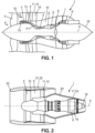
- a turbomachine 1, illustrated in figure 1 has an X axis and comprises, from upstream to downstream in the direction of circulation of the gases within the turbomachine, a fan 2, a low pressure compressor 3, a high pressure compressor 4, a combustion chamber 5, a high pressure turbine 6 and a low pressure turbine 7.
- upstream and downstream are defined in relation to the direction of gas flow within the turbomachine.
- axial, radial and circumferential are defined relative to the X axis of the turbomachine.
- the air F entering at the blower is divided into a primary air flow F1 circulating through a so-called primary vein 8 and into a secondary air flow F2 circulating through a so-called secondary vein 9, surrounding the primary vein 8.
- the low and high pressure compressors 3, 4, the combustion chamber 5 and the high and low pressure turbines 6, 7 are located at the level of the primary vein 8.
- the high-pressure turbine 6 drives the high-pressure compressor 4 via a so-called high-pressure shaft.
- the low-pressure turbine 7 drives the low-pressure compressor 3 and the blower 2, via a so-called low-pressure shaft and possibly via a speed reducer in the case where the rotation speed of the blower 2 is lower than the rotation speed of the low-pressure compressor 3.
- turbomachine 1 Most of the thrust generated by turbomachine 1 is produced by secondary flow F2, downstream of fan 2.
- the fan 2 is surrounded by a fan casing 10, a so-called intermediate casing 11 being located downstream of the fan casing 10.
- the intermediate casing 11 comprises a radially external shroud 12 located in the extension of the fan casing 10 and a so-called inter-vein part 13, located between the primary 8 and secondary 9 veins.
- the inter-vein part 13 has a separating spout 14 at its upstream end and is connected to the external ferrule 12 by so-called structural arms 15.
- the turbomachine 1 further comprises a central casing 16, located downstream of the inter-stream portion 13 of the intermediate casing 11, and an exhaust casing 17, located downstream of the central casing 16 and on which an ejection cone 18 is attached.
- the exhaust casing 17 comprises a radially internal shell 19 and a radially external shell 20, connected by blades extending radially.
- the internal shells 19 and external shells 20 of the exhaust casing 17 delimit between them the downstream end of the primary stream 8.
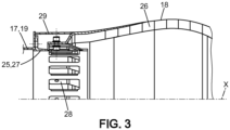
- the nacelle 21 of the propulsion unit conventionally comprises a fan nacelle 22, surrounding the fan 2 as well as the fan casing 10 and the external shroud 12 of the intermediate casing 11.
- the fan nacelle 22 forms an air inlet lip 23 at its upstream end.
- the nacelle 21 further comprises an engine nacelle 24 surrounding the zones of the turbomachine 1 comprising the high-pressure compressor 4, the combustion chamber 5, the high-pressure turbine 6, and the low-pressure turbine 7 in particular.
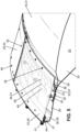
- the upstream end of the ejection cone 18 is connected to the downstream end of the internal shell 19 of the exhaust casing 17 by means of an annular connecting flange 25 (also visible in FIG. figure 4 ).
- the cone 18 is generally made of ceramic matrix composite material, also referred to by the English acronym CMC.
- the cone 18 may in particular comprise a radially external skin and a radially internal skin delimiting between them an acoustic box in which an internal acoustic structure 26 is housed.
- the internal shell 19 of the exhaust casing 18 is metallic, for example made of titanium alloy.
- the flange 25 is metallic, for example made of titanium alloy, and comprises an annular part 27 of axis X, from which flexible legs 28 extend.
- the legs 28 are regularly distributed around the circumference.
- Such flexible or supple tabs 28 make it possible to compensate for the differential expansion phenomena occurring between the internal shell 19 of the exhaust casing 17 and the cone 18, these two elements 17, 18 being made of different materials.
- An annular fairing 29 formed from a single piece can surround the legs and extend in the extension of the internal ferrule 19 and the external skin of the cone 18.
- the exhaust assembly is the assembly formed by the exhaust casing 17, the ejection cone 18, the flange 25 and the fairing 29.
- the assembly and/or disassembly of such an assembly is generally carried out downstream and via the interior volume of said assembly, which may be difficult for an operator to carry out, since the aforementioned volume may be small.
- the invention aims to remedy this drawback in a simple, reliable and inexpensive manner.
- the invention relates to an assembly for a turbomachine comprising an ejection cone and an exhaust casing comprising an annular inner shell, the ejection cone and the exhaust casing extending around an axis, the ejection cone comprising a radially outer skin extending in the extension of said inner shell and a radially inner skin delimiting a box with the outer skin, the upstream end of the cone being fixed to the inner shell by means of connecting lugs, the assembly comprising an annular fairing located radially outside said lugs and extending axially between the inner shell of the exhaust casing and the outer skin of the ejection cone, said fairing extending in the extension of said inner shell and the outer skin, characterized in that the fairing is sectorized and is formed of several angular sectors arranged circumferentially end to end, and in that it has an annular seal extending radially between the downstream end of the fairing and the cone.
- the upstream and downstream terms are defined in relation to the direction of gas flow within the turbomachine.
- the axial, radial and circumferential terms are defined in relation to the axis of the cone and the exhaust casing, which coincides with the axis of the turbomachine.
- the use of several angular sectors for the production of the fairing makes it easier to assemble and disassemble the assembly.
- the connecting legs can be flexible or elastically deformable.
- the fairing may comprise an upstream end fixed to the inner shell of the exhaust casing or to a flange fixed to said inner shell, and an opposite downstream zone supported by a support member, said support member extending radially between said downstream zone of the fairing and the cone.
- the support member can be arranged radially between the fairing and the outer skin of the cone.
- the support member may be radially deformable.
- support members can be arranged radially between the fairing and the cone.
- the support members can be regularly distributed around the circumference.
- Each support member may comprise a radially internal flat part, fixed to the upstream end of the cone, in particular to the upstream end of the external skin, a radially external flat part, fixed to the fairing, and a median flat part extending radially between the internal and external parts.
- the internal part and/or the external part may be attached by welding, riveting or bolting to the fairing or cone.
- the middle portion of each support member may extend obliquely to the radial direction.
- the support member may have a general Z shape.
- the assembly includes an annular seal extending radially between the downstream end of the fairing and the cone.
- Such a seal prevents a gas leak flow from the primary vein from entering the volume located radially inside the fairing.
- the seal may extend in particular between said downstream end of the fairing and the external skin of the cone.
- the annular middle part is thus conical.
- Said middle part can extend from upstream to downstream and radially from outside to inside.
- the embodiment is used when the pressure in the secondary vein is higher or lower than the pressure radially inside the fairing, so as to press the free radial end of the seal against the fairing or the cone due to the pressure difference on one side and the other of the middle part of the seal.
- the seal may have a hollow rounded section area.
- Such a seal may include an enlarged base secured to the fairing or cone, particularly to the outer skin of the cone, with the hollow rounded section area extending from the base.
- Circumferential ends of two adjacent fairing sectors may overlap circumferentially.
- Such a covering makes it possible to limit the leakage flow radially inwards from the primary vein.
- the overlap area may extend over a range of 10 to 100 mm, for example.
- the fairing sectors may be secured to each other at the overlap area, for example by means of removable fastening means.
- the removable fastening means comprise, for example, bolts.
- the adjacent angular sectors may be secured to each other and/or secured to the inner shell of the exhaust housing by means of removable fastening means.
- the upstream end of the fairing may be fixed to the inner shell of the exhaust casing by means of an annular connecting rail.
- the rail may comprise a generally L-shaped section, comprising a radial annular portion fixed to the inner shell of the exhaust casing, and an annular axial portion used for fixing the upstream end of the fairing.
- the assembly may include an annular flange connecting the inner ferrule of the exhaust casing to the cone, the flange including said flexible connecting tabs.
- the flange comprises an annular portion fixed to the inner shell of the exhaust casing, the connecting tabs extending axially from the annular portion.
- the annular portion may or may not be integral with the tabs.
- the tabs may be flat and may each extend along an axis parallel to the axis of the cone and the exhaust casing.
- the flange may be sectorized and may be formed of several angular sectors arranged circumferentially adjacent or end to end, each flange sector comprising at least one lug extending rectilinearly along an axis parallel to the axis of the cone.
- the assembly may comprise sealing members mounted circumferentially between the lugs. Said members may be formed by sheets or foils mounted between the lugs.
- a foam material such as honeycomb, can be mounted in the acoustic box.
- the invention also relates to a turbomachine comprising at least one assembly of the aforementioned type.
- FIG. 5 to 11 illustrate an exhaust assembly for an aircraft turbomachine 1 according to one embodiment of the invention.
- This assembly comprises an exhaust casing 17 (not shown in these figures) comprising, as previously, a radially internal annular shell 19 and a radially external annular shell 20, connected by radial blades.
- the assembly further comprises an ejection cone 18 comprising a radially internal skin 30 and a radially external skin 31, delimiting between them an acoustic box 32.
- a cellular material for example honeycomb, can be housed in the box. acoustic 32. This material can be brazed, glued or co-injected with one or the other of the inner 30 or outer 31 skins, for example.
- the inner 30 and outer 31 skins are fixed to each other at their upstream 33 and downstream 34 ends, by gluing, brazing or by means of fixing means such as rivets or bolts 35.
- An annular flange 36 connects the downstream end of the internal shell 19 of the exhaust casing 17 and the upstream end 33 of the ejection cone 18.
- the flange 36 comprises, from upstream to downstream, a radial annular fixing part 37, an axial annular part 38, connecting lugs 39 and an axial annular fixing part 40, which may be annular or formed by the ends of the lugs 39.
- Part 37 is fixed to the internal shell 19 of the exhaust casing 17, for example by means of bolts 41.
- Part 40 is fixed to the upstream ends of the skins of the cone, for example by means of bolts 35.
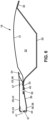
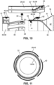
- a 29 annular and sectored fairing ( figure 8 ) surrounds the legs 39 and the upstream ends 33 of the inner 30 and outer 31 skins.
- the fairing 29 extends in the extension of the outer surface of the inner shell 19 of the exhaust casing 17 and in the extension of the outer skin 31, so as to ensure surface continuity of the primary vein 8 in this zone.
- the fairing 29 is thus made up of several sectors 42, for example 4 sectors, regularly distributed on the circumference and arranged end to end.
- the upstream end of each sector 42 is fixed on the part 37 of the flange 36, by means of an annular rail 43 of L-shaped section.
- Said rail 43 comprises a radial part 44 fixed to the radial part 37 of the flange 36 by means of at least part of the fixing means 41 or by means of separate fixing means, and an axial part 45 fixed to the upstream end of each sector 42, by means of fixing means, in particular removable, for example bolts 46.
- the circumferential ends of the adjacent sectors 42 overlap at the level of overlapping zones 42a and are fixed relative to each other at the level of these overlapping zones 42a, by means of removable fixing means 47.
- Support members 48 regularly distributed over the circumference extend radially between the upstream end 33 of the external skin 31 and a downstream zone of the fairing 29.
- Each support member 48 comprises a radially internal upstream part 49 fixed by any appropriate means, for example by riveting, to the upstream ends 33 of the internal and/or external skins 30, 31, an oblique middle part 50 forming an angle with the axial direction and the radial direction, and a radially external downstream part 51 fixed by any appropriate means to the sectors of the fairing 29, preferably by means of removable fixing means such as bolts 52.
- An annular seal 53 is mounted radially inside the fairing 29.
- Said seal 53 may be sectorized or not and comprises a radially external downstream part 54, fixed by any suitable means 55, to the downstream end of the fairing 29, an oblique middle part 56 and a rounded radially internal upstream part 57 held elastically in abutment on the upstream end 33 of the external skin 31.
- the middle part 56 is formed of adjacent fingers, the fingers being elastically deformable individually relative to each other.
- the support of the internal part 57 of the seal 53 on the external skin 31 is for example a linear support, due to the rounded shape of said internal part 57.
- the middle portion 56 is frustoconical and is inclined from upstream to downstream and radially from inside to outside.
- the seal 53 makes it possible to limit or prevent the introduction of hot gases from the turbine 7 into the volume located radially inside the fairing 29.
- Such an embodiment can in particular be used when the pressure in the volume located radially inside the fairing 29 is greater than the pressure of the gases at the level of the primary vein 8, so as to keep the internal end of the seal 53 pressing on the external skin 31, due to the pressure difference.
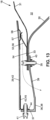
- FIG 12 illustrates another embodiment of the invention, which differs from that previously described with reference to the Figures 5 to 11 in that the middle portion 56 extends from upstream to downstream and radially from outside to inside.
- Such an embodiment can in particular be used when the pressure in the volume located radially inside the fairing 29 is lower than the pressure of the gases at the level of the primary vein 8, so as to keep the internal end 57 of the seal 53 pressing on the external skin 31, due to the pressure difference.
- FIG 13 illustrates another embodiment, which differs from those illustrated with reference to Figures 5 to 12 in that the part 54 is located upstream and radially to the inside and is fixed to the outer skin 31, the part 57 being located downstream and radially to the outside and comes to bear on a fixed support element 58 on the fairing 29.
- the middle part 56 is inclined from upstream to downstream and radially from the inside to the outside.
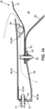
- annular seal 53 comprises a radially external base 59 fixed to the fairing 29 and a portion 60 of hollow circular section, elastically deformable in the radial direction and coming to bear on the external skin 31.
- the seal 53 can be sectorized.
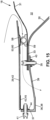
- FIG 15 illustrates another embodiment of the invention, which differs from that illustrated in the figure 14 in that the base 59 is radially internal and is fixed to the external skin 31, the circular section part 60 coming to bear on a support element 58 fixed to the fairing 29.
- FIG 16 illustrates another embodiment in which sealing members 61 are mounted circumferentially between the legs 39.
- Said members 61 can be formed by sheets or foils mounted between the legs 39. These members 61 make it possible to further limit the leakage rates of hot gases from the primary vein 8.
- the legs 39 can be made by separate parts of the flange 36, the upstream ends of the legs 39 then being fixed to the axial part 38 of the flange 36.
Landscapes
- Engineering & Computer Science (AREA)
- Mechanical Engineering (AREA)
- General Engineering & Computer Science (AREA)
- Chemical & Material Sciences (AREA)
- Combustion & Propulsion (AREA)
- Turbine Rotor Nozzle Sealing (AREA)
- Structures Of Non-Positive Displacement Pumps (AREA)
Description
- L'invention concerne un ensemble pour une turbomachine, en particulier un ensemble d'éjection pour un turboréacteur ou un turbopropulseur d'avion.
- Un ensemble propulsif pour un aéronef, également appelé système propulsif intégré, comporte classiquement une turbomachine, par exemple un turboréacteur, une nacelle et un mât ou pylône d'accrochage destiné à permettre l'accrochage de l'ensemble propulsif sur une partie structurelle, par exemple sous l'aile, de l'aéronef.
- La turbomachine est par exemple un turboréacteur à double flux. Une telle turbomachine 1, illustrée à la
figure 1 , présente un axe X et comporte de l'amont vers l'aval dans le sens de circulation des gaz au sein de la turbomachine, une soufflante 2, un compresseur basse pression 3, un compresseur haute pression 4, une chambre de combustion 5, une turbine haute pression 6 et une turbine basse pression 7. - Dans la suite de la description, les termes amont et aval sont définis par rapport au sens de circulation des gaz au sein de la turbomachine.
- Par ailleurs, les termes axial, radial et circonférentiel sont définis par rapport à l'axe X de la turbomachine.
- L'air F entrant au niveau de la soufflante est divisé en un flux d'air primaire F1 circulant au travers d'une veine dite primaire 8 et en un flux d'air secondaire F2 circulant au travers d'une veine dite secondaire 9, entourant la veine primaire 8. Les compresseurs basse et haute pression 3, 4, la chambre de combustion 5 et les turbines haute et basse pression 6, 7 sont situés au niveau de la veine primaire 8.
- La turbine haute pression 6 entraîne le compresseur haute pression 4 par l'intermédiaire d'un arbre dit haute pression. La turbine basse pression 7 entraîne le compresseur basse pression 3 et la soufflante 2, au travers d'un arbre dit basse pression et éventuellement au travers d'un réducteur de vitesses dans le cas où la vitesse de rotation de la soufflante 2 est plus faible que la vitesse de rotation du compresseur basse pression 3.
- La majeure partie de la poussée générée par la turbomachine 1 est produite par le flux secondaire F2, en aval de la soufflante 2.
- La soufflante 2 est entourée par un carter de soufflante 10, un carter dit intermédiaire 11 étant situé en aval du carter de soufflante 10. Le carter intermédiaire 11 comporte une virole radialement externe 12 située dans le prolongement du carter de soufflante 10 et une partie dite inter-veine 13, située entre les veine primaire 8 et secondaire 9. La partie inter-veine 13 comporte un bec séparateur 14 à son extrémité amont et est reliée à la virole externe 12 par des bras dit structuraux 15.
- La turbomachine 1 comporte par ailleurs un carter central 16, situé en aval de la partie inter-veine 13 du carter intermédiaire 11, et un carter d'échappement 17, situé en aval du carter central 16 et sur lequel est rapporté un cône d'éjection 18. Le carter d'échappement 17 comporte une virole radialement interne 19 et une virole radialement externe 20, reliées par des pales s'étendant radialement. Les viroles interne 19 et externe 20 du carter d'échappement 17 délimitent entre elles l'extrémité aval de la veine primaire 8.
- Comme illustré à la
figure 2 , la nacelle 21 de l'ensemble propulsif comporte classiquement une nacelle de soufflante 22, entourant la soufflante 2 ainsi que le carter de soufflante 10 et la virole externe 12 du carter intermédiaire 11. La nacelle de soufflante 22 forme une lèvre d'entrée d'air 23 à son extrémité amont. La nacelle 21 comporte en outre une nacelle de moteur 24 entourant les zones de la turbomachine 1 comportant le compresseur haute pression 4, la chambre de combustion 5, la turbine haute pression 6, et la turbine basse pression 7 notamment. - Comme cela est illustré à la
figure 3 et est connu du documentFR 3 084 916 figure 4 ). Le cône 18 est généralement réalisé en matériau composite à matrice céramique, également désigné sous l'acronyme anglais CMC. Le cône 18 peut en particulier comporter une peau radialement externe et une peau radialement interne délimitant entre elle un caisson acoustique dans lequel est logée une structure acoustique interne 26. La virole interne 19 du carter d'échappement 18 est métallique, par exemple en alliage de titane. - La bride 25 est métallique, par exemple an alliage de titane, et comporte une partie annulaire 27 d'axe X, à partir de laquelle s'étendent des pattes flexibles 28. Les pattes 28 sont régulièrement réparties sur la circonférence.
- De telles pattes souples ou flexibles 28 permettent de compenser les phénomènes de dilatation différentielle intervenant entre la virole interne 19 du carter d'échappement 17 et le cône 18, ces deux éléments 17, 18 étant réalisés dans des matériaux différents.
- Un carénage annulaire 29 formé d'une seule pièce peut venir entourer les pattes et s'étendre dans le prolongement de la virole interne 19 et de la peau externe du cône 18.
- On appelle ensemble d'échappement l'ensemble formé par le carter d'échappement 17, le cône d'éjection 18, la bride 25 et le carénage 29. En fonction des configurations, le montage et/ou le démontage d'un tel ensemble est généralement réalisé par l'aval et par le volume intérieur dudit ensemble, ce qui peut être difficile à réaliser par un opérateur, le volume précité pouvant être de faible dimension.
- Un ensemble pour une turbomachine selon l'art antérieur est également divulgué dans le document
FR2949820 - L'invention vise à remédier à cet inconvénient, de manière simple, fiable et peu onéreuse.
- A cet effet, l'invention concerne un ensemble pour une turbomachine comportant un cône d'éjection et un carter d'échappement comportant une virole interne annulaire, le cône d'éjection et le carter d'échappement s'étendant autour d'un axe, le cône d'éjection comportant une peau radialement externe s'étendant dans le prolongement de ladite virole interne et une peau radialement interne délimitant un caisson avec la peau externe, l'extrémité amont du cône étant fixée à la virole interne par l'intermédiaire de pattes de liaison, l'ensemble comportant un carénage annulaire situé radialement à l'extérieur desdites pattes et s'étendant axialement entre la virole interne du carter d'échappement et la peau externe du cône d'éjection, ledit carénage s'étendant dans le prolongement de ladite virole interne et de la peau externe, caractérisé en ce que le carénage est sectorisé et est formé de plusieurs secteurs angulaires agencés circonférentiellement bout à bout, et en ce qu'il comporte un joint annulaire s'étendant radialement entre l'extrémité aval du carénage et le cône.
- Les termes amont et aval sont définis par rapport au sens de circulation des gaz au sein de la turbomachine. Les termes axial, radial et circonférentiel sont définis par rapport à l'axe du cône et du carter d'échappement, qui est confondu avec l'axe de la turbomachine. L'utilisation de plusieurs secteurs angulaires pour la réalisation du carénage permet de faciliter le montage et le démontage de l'ensemble.
- Le caisson peut être un caisson acoustique, c'est-à-dire ayant notamment pour fonction d'atténuer les bruits.
- Les pattes de liaison peuvent être souples ou élastiquement déformables.
- Le nombre de secteurs angulaires peut être compris entre 2 et 16 et est par exemple égal à 4.
- Le carénage peut comporter une extrémité amont fixée à la virole interne du carter d'échappement ou à une bride fixée à ladite virole interne, et une zone aval opposée supportée par un organe support, ledit organe support s'étendant radialement entre ladite zone aval du carénage et le cône.
- Plus particulièrement, l'organe support peut être agencé radialement entre le carénage et la peau externe du cône.
- L'organe support peut être radialement déformable.
- Plusieurs organes support peuvent être agencés radialement entre le carénage et le cône. Les organes support peuvent être régulièrement répartis sur la circonférence.
- Chaque organe support peut comporter une partie plane radialement interne, fixée à l'extrémité amont du cône, en particulier à l'extrémité amont de la peau externe, une partie plane radialement externe, fixée au carénage, et une partie plane médiane s'étendant radialement entre les parties interne et externe. La partie interne et/ou la partie externe peuvent être fixées par soudage, rivetage ou boulonnage au carénage ou au cône. La partie médiane de chaque organe support peut s'étendre de façon oblique par rapport à la direction radiale. L'organe support peut présenter une forme générale en Z.
- L'ensemble comporte un joint annulaire s'étendant radialement entre l'extrémité aval du carénage et le cône.
- Un tel joint empêche qu'un débit de fuite de gaz issu de la veine primaire pénètre dans le volume situé radialement à l'intérieur du carénage.
- Le joint peut s'étendre en particulier entre ladite extrémité aval du carénage et la peau externe du cône.
- Le joint peut être déformable dans la direction radiale.
- Le joint peut comporter une partie de fixation au carénage ou au cône, et une partie médiane en forme de tôle, s'étendant de façon oblique par rapport à la direction radiale.
- La partie médiane annulaire est ainsi conique.
- Ladite partie médiane peut comporter une série de doigts adjacents, les doigts étant déformables élastiquement de façon individuelle les uns par rapport aux autres.
- Le joint peut comporter une extrémité arrondie en appui sur le cône ou le carénage, directement ou par l'intermédiaire d'un élément d'appui fixé sur ledit cône ou ledit carénage. Une telle extrémité arrondie permet de réaliser un appui linéique étanche avec la surface du cône ou du carénage sur laquelle elle vient en appui.
- Ladite partie médiane peut s'étendre de l'aval vers l'amont et radialement de l'extérieur vers l'intérieur.
- Ladite partie médiane peut s'étendre de l'amont vers l'aval et radialement de l'extérieur vers l'intérieur.
- En fonction de la position radialement externe ou radialement interne de la partie de fixation du joint et de l'orientation de l'inclinaison de la partie médiane du joint, la forme de réalisation est utilisée lorsque la pression dans la veine secondaire est supérieure ou inférieure à la pression radialement à l'intérieur du carénage, de manière à plaquer l'extrémité radiale libre du joint sur le carénage ou le cône du fait de la différence de pression d'un côté et de l'autre de la partie médiane du joint.
- Le joint peut comporter une zone de section arrondie creuse.
- Un tel joint peut comporter une base élargie fixée au carénage ou au cône, en particulier à la peau externe du cône, la zone de section arrondie creuse s'étendant depuis la base.
- Des extrémités circonférentielles de deux secteurs de carénage adjacents peuvent se recouvrir circonférentiellement.
- Un tel recouvrement permet de limiter le débit de fuite radialement vers l'intérieur depuis la veine primaire.
- La zone de recouvrement peut s'étendre sur une plage comprise entre 10 et 100 mm, par exemple. Les secteurs de carénage peuvent être fixés les uns aux autres au niveau de la zone de recouvrement, par exemple par l'intermédiaire de moyens de fixation amovibles. Les moyens de fixation amovibles comportent par exemple des boulons.
- Les secteurs angulaires adjacents peuvent être fixés l'un à l'autre et/ou fixés à la virole interne du carter d'échappement par l'intermédiaire de moyens de fixation amovibles.
- Les moyens de fixation amovibles comportent par exemple des boulons.
- De tels moyens amovibles permettent de pouvoir démonter aisément le carénage. L'extrémité amont du carénage peut être fixée à la virole interne du carter d'échappement par l'intermédiaire d'un rail annulaire de liaison. Le rail peut comporter une section de forme générale en L, comportant une partie annulaire radiale fixée à la virole interne du carter d'échappement, et une partie axiale annulaire servant à la fixation de l'extrémité amont du carénage.
- L'ensemble peut comporter une bride annulaire reliant la virole interne du carter d'échappement au cône, la bride comportant lesdites pattes de liaison souples.
- La bride comporte une partie annulaire fixée à la virole interne du carter d'échappement, les pattes de liaison s'étendant axialement depuis la partie annulaire. La partie annulaire peut venir ou non de matière avec les pattes. Les pattes peuvent être planes et peuvent s'étendre chacune selon un axe parallèle à l'axe du cône et du carter d'échappement.
- La bride peut être sectorisée et peut être formée de plusieurs secteurs angulaires agencés circonférentiellement de façon adjacente ou bout à bout, chaque secteur de bride comportant au moins une patte s'étendant de façon rectiligne selon un axe parallèle à l'axe du cône. L'ensemble peut comporter des organes d'étanchéité montés circonférentiellement entre les pattes. Lesdits organes peuvent être formés par des tôles ou des clinquants montés entre les pattes.
- Un matériau alvéolaire, par exemple en nid d'abeille, peut être monté dans le caisson acoustique.
- Le carénage peut être métallique, par exemple en alliage à base de nickel ou de titane, par exemple en Inconel. Le cône peut être réalisé, en tout ou partie, en matériau composite à matrice céramique, également connu sous l'acronyme anglais CMC. Le carter d'échappement peut être métallique, par exemple en alliage à base de nickel ou de titane. Le montage d'un tel ensemble peut comporter l'une ou plusieurs des étapes consistant à :
- monter le rail de liaison annulaire et/ou la bride sur le carter d'échappement,
- monter le sous-ensemble formé par la peau interne, la peau externe et/ou un matériau acoustique contenu dans le caisson acoustique, sur la bride souple,
- monter les secteurs angulaires du carénage.
- L'invention concerne également une turbomachine comportant au moins un ensemble du type précité.
-
- [
Fig. 1 ] est une vue schématique en coupe axiale d'une turbomachine de l'art antérieur, - [
Fig. 2 ] est une vue schématique en coupe axiale d'un ensemble propulsif de l'art antérieur, [Fig. 3 ] est une demie vue en coupe axiale d'une partie d'un ensemble d'éjection de turbomachine de l'art antérieur, - [
Fig. 4 ] est une vue en perspective d'une bride de liaison entre un cône d'éjection et un carter d'échappement, conformément à l'art antérieur, - [
Fig. 5 ] est une vue en perspective et en coupe axiale d'une partie d'un ensemble selon une forme de réalisation de l'invention, - [
Fig. 6 ] est une vue en section d'une partie dudit ensemble, - [
Fig. 7 ] est une vue détail de lafigure 6 , les moyens de fixation étant représentés, - [
Fig. 8 ] est une vue en perspective illustrant les secteurs de carénage, - [
Fig. 9 ] est une vue en section radiale d'une partie de l'ensemble, - [
Fig. 10 ] est une vue éclatée, en perspective et en coupe axiale, d'une partie de l'ensemble, - [
Fig. 11 ] est une vue de face et éclatée partiellement, illustrant les différents secteurs du carénage autour du reste de l'ensemble, - [
Fig. 12 ] est une vue correspondant à lafigure 7 , illustrant une autre forme de réalisation de l'invention, - [
Fig. 13 ] est une vue correspondant à lafigure 7 , illustrant une autre forme de réalisation de l'invention, - [
Fig. 14 ] est une vue correspondant à lafigure 7 , illustrant une autre forme de réalisation de l'invention, - [
Fig. 15 ] est une vue correspondant à lafigure 7 , illustrant une autre forme de réalisation de l'invention, - [
Fig. 16 ] est une vue en perspective d'une partie d'un ensemble selon l'invention, le carénage ayant été retiré. - Les
figures 5 à 11 illustrent un ensemble d'échappement pour une turbomachine 1 d'aéronef selon une forme de réalisation de l'invention. Cet ensemble comporte un carter d'échappement 17 (non représenté sur ces figures) comportant, comme précédemment, une virole annulaire radialement interne 19 et une virole annulaire radialement externe 20, reliées par des pales radiales. - L'ensemble comporte en outre un cône d'éjection 18 comportant une peau radialement interne 30 et une peau radialement externe 31, délimitant entre elles un caisson acoustique 32. Un matériau alvéolaire, par exemple en nid d'abeille, peut être logé dans le caisson acoustique 32. Ce matériau peut être brasé, collé ou co-injecté avec l'une ou l'autre des peaux interne 30 ou externe 31, par exemple. Les peaux interne 30 et externe 31 sont fixées l'une à l'autre à leur extrémités amont 33 et aval 34, par collage, brasage ou par l'intermédiaire de moyens de fixation tels que des rivets ou des boulons 35.
- Une bride annulaire 36, sectorisé ou non, relie l'extrémité aval de la virole interne 19 du carter d'échappement 17 et l'extrémité amont 33 du cône d'éjection 18.
- La bride 36 comporte, de l'amont vers l'aval, une partie annulaire radiale de fixation 37, une partie annulaire axiale 38, des pattes de liaison 39 et une partie annulaire axiale de fixation 40, qui peut être annulaire ou formée par les extrémités des pattes 39.
- La partie 37 est fixée à la virole interne 19 du carter d'échappement 17, par exemple par l'intermédiaire de boulons 41. La partie 40 est fixée aux extrémités amonts des peaux du cône, par exemple par l'intermédiaire des boulons 35.
- Un carénage 29 annulaire et sectorisé (
figure 8 ) entoure les pattes 39 et les extrémités amonts 33 des peaux interne 30 et externe 31. Le carénage 29 s'étend dans le prolongement de la surface externe de la virole interne 19 du carter d'échappement 17 et dans le prolongement de la peau externe 31, de manière à assurer une continuité de surface de la veine primaire 8 dans cette zone. - Le carénage 29 est ainsi constitué de plusieurs secteurs 42, par exemple 4 secteurs, régulièrement répartis sur la circonférence et agencés bout à bout. L'extrémité amont de chaque secteur 42 est fixée sur la partie 37 de la bride 36, par l'intermédiaire d'un rail annulaire 43 de section en L. Ledit rail 43 comporte une partie radiale 44 fixée à la partie radiale 37 de la bride 36 par l'intermédiaire d'au moins une partie des moyens de fixation 41 ou par l'intermédiaire de moyens de fixation distincts, et une partie axiale 45 fixée à l'extrémité amont de chaque secteur 42, par l'intermédiaire de moyens de fixation, en particulier amovibles, par exemple des boulons 46. Comme cela est visible à la
figure 9 , les extrémités circonférentielles des secteurs 42 adjacents se recouvrent au niveau de zones de recouvrement 42a et sont fixés les uns par rapport aux autres au niveau de ces zones de recouvrement 42a, par l'intermédiaire de moyens de fixation amovibles 47. - Des organes supports 48 régulièrement répartis sur la circonférence s'étendent radialement entre l'extrémité amont 33 de la peau externe 31 et une zone aval du carénage 29. Chaque organe support 48 comporte une partie amont 49 radialement interne fixée par tous moyens approprié, par exemple par rivetage, aux extrémités amonts 33 des peaux interne et/ou externe 30, 31, une partie médiane oblique 50 formant un angle avec la direction axiale et la direction radiale, et une partie aval 51 radialement externe fixée par tous moyens appropriés aux secteurs du carénage 29, de préférence par l'intermédiaire de moyens de fixation amovibles tels que des boulons 52.
- Un joint annulaire 53 est montée radialement à l'intérieur du carénage 29. Ledit joint 53 peut être sectorisé ou non et comporte une partie aval radialement externe 54, fixée par tous moyens appropriés 55, à l'extrémité aval du carénage 29, une partie médiane oblique 56 et une partie amont 57 radialement interne arrondie maintenue élastiquement en appui sur l'extrémité amont 33 de la peau externe 31. La partie médiane 56 est formés de doigts adjacents, les doigts étant déformables élastiquement de façon individuelle les uns par rapport aux autres.
- L'appui de la partie interne 57 du joint 53 sur la peau externe 31 est par exemple un appui linéique, du fait de la forme arrondie de ladite partie interne 57.
- Dans cette forme de réalisation, la partie médiane 56 est tronconique et est inclinée de l'amont vers l'aval et radialement de l'intérieur vers l'extérieur.
- Le joint 53 permet de limiter ou d'éviter l'introduction de gaz chauds issus de la turbine 7 dans le volume situé radialement à l'intérieur du carénage 29.
- Une telle forme de réalisation peut notamment être utilisée lorsque la pression dans le volume situé radialement à l'intérieur du carénage 29 est supérieure à la pression des gaz au niveau de la veine primaire 8, de façon à maintenir l'extrémité interne du joint 53 en appui sur la peau externe 31, du fait de la différence de pression.
- Les
figures 10 et 11 illustrent le procédé montage d'un tel ensemble. Un tel procédé comporte les étapes successives consistant à : - monter le rail de liaison annulaire 43 et la bride 36 sur le carter d'échappement 17,
- monter le sous-ensemble formé par la peau interne 30, la peau externe 31 et le matériau acoustique contenu dans le caisson acoustique 32, sur la bride 36 souple,
- monter les secteurs angulaires 42 du carénage 29.
- La
figure 12 illustre une autre forme de réalisation de l'invention, qui diffère de celle décrite précédemment en référence auxfigures 5 à 11 en ce que la partie médiane 56 s'étend de l'amont vers l'aval et radialement de l'extérieur vers l'intérieur. - Une telle forme de réalisation peut notamment être utilisée lorsque la pression dans le volume situé radialement à l'intérieur du carénage 29 est inférieure à la pression des gaz au niveau de la veine primaire 8, de façon à maintenir l'extrémité interne 57 du joint 53 en appui sur la peau externe 31, du fait de la différence de pression.
- La
figure 13 illustre une autre forme de réalisation, qui diffère de celles illustrées en référence auxfigures 5 à 12 en ce que la partie 54 est située à l'amont et radialement à l'intérieur et est fixée à la peau externe 31, la partie 57 étant située en aval et radialement à l'extérieur et vient en appui sur un élément d'appui fixé 58 sur le carénage 29. Dans cette forme de réalisation également, la partie médiane 56 est inclinée de l'amont vers l'aval et radialement de l'intérieur vers l'extérieur. - La
figure 14 illustre une autre forme de réalisation dans laquelle le joint annulaire 53 comporte une base 59 radialement externe fixée au carénage 29 et une partie 60 de section circulaire creuse, élastiquement déformable dans la direction radiale et venant en appui sur la peau externe 31. Comme précédemment, le joint 53 peut être sectorisé. - La
figure 15 illustre une autre forme de réalisation de l'invention, qui diffère de celle illustrée à lafigure 14 en ce que la base 59 est radialement interne et est fixée à la peau externe 31, la partie de section circulaire 60 venant en appui sur un élément d'appui 58 fixé au carénage 29. - La
figure 16 illustre une autre forme de réalisation dans laquelle des organes d'étanchéité 61 sont montés circonférentiellement entre les pattes 39. Lesdits organes 61 peuvent être formés par des tôles ou des clinquants montés entre les pattes 39. Ces organes 61 permettent de limiter encore les débits de fuite de gaz chauds issus de la veine primaire 8. - Les pattes 39 peuvent être réalisées par des pièces distinctes de la bride 36, les extrémités amont des pattes 39 étant alors fixées à la partie axiale 38 de la bride 36.
Claims (9)
- Ensemble pour une turbomachine (1) comportant un cône d'éjection (18) et un carter d'échappement (17) comportant une virole interne annulaire (19), le cône d'éjection (18) et le carter d'échappement (17) s'étendant autour d'un axe (X), le cône d'éjection (18) comportant une peau radialement externe (31) s'étendant dans le prolongement de ladite virole interne (19) et une peau radialement interne (30) délimitant un caisson (32) avec la peau externe (31), l'extrémité amont (33) du cône (18) étant fixée à la virole interne (19) par l'intermédiaire de pattes de liaison (39), l'ensemble comportant un carénage annulaire (29) situé radialement à l'extérieur desdites pattes (39) et s'étendant axialement entre la virole interne (19) du carter d'échappement (17) et la peau externe (31) du cône d'éjection (18), ledit carénage (29) s'étendant dans le prolongement de ladite virole interne (19) et de la peau externe (31), caractérisé en ce que le carénage (29) est sectorisé et est formé de plusieurs secteurs angulaires (42) agencés circonférentiellement bout à bout, et en ce qu'il comporte un joint annulaire (53) s'étendant radialement entre l'extrémité aval du carénage (29) et le cône (18).
- Ensemble selon la revendication 1, caractérisé en ce que le carénage (29) comporte une extrémité amont fixée à la virole interne (19) du carter d'échappement (17) ou à une bride (36) fixée à ladite virole interne (17), et une zone aval opposée supportée par un organe support (48), ledit organe support (48) s'étendant radialement entre ladite zone aval du carénage (29) et le cône (18).
- Ensemble selon la revendication 1 ou 2, caractérisé en ce que le joint (53) comporte une partie de fixation (54) au carénage (29) ou au cône (18), et une partie médiane (56) en forme de tôle, s'étendant de façon oblique par rapport à la direction radiale.
- Ensemble selon la revendication 3, caractérisé en ce que ladite partie médiane (56) s'étend de l'aval vers l'amont et radialement de l'extérieur vers l'intérieur.
- Ensemble selon la revendication 3, caractérisé en ce que ladite partie médiane (56) s'étend de l'amont vers l'aval et radialement de l'extérieur vers l'intérieur.
- Ensemble selon l'une des revendications 1 à 5, caractérisé en ce que le joint (53) comporte une zone de section arrondie creuse (60).
- Ensemble selon l'une des revendications 1 à 6, caractérisé en ce que des extrémités circonférentielles de deux secteurs de carénage (42) adjacents se recouvrent circonférentiellement (42a).
- Ensemble selon l'une des revendications 1 à 7, caractérisé en ce que les secteurs angulaires adjacents (42) sont fixés l'un à l'autre et/ou fixés à la virole interne (19) du carter d'échappement (17) par l'intermédiaire de moyens de fixation amovibles (46, 47).
- Turbomachine (1) comportant au moins un ensemble selon l'une des revendications 1 à 8.
Applications Claiming Priority (2)
| Application Number | Priority Date | Filing Date | Title |
|---|---|---|---|
| FR2011383A FR3115832B1 (fr) | 2020-11-05 | 2020-11-05 | Ensemble pour une turbomachine |
| PCT/FR2021/051936 WO2022096822A1 (fr) | 2020-11-05 | 2021-11-03 | Ensemble pour une turbomachine |
Publications (2)
| Publication Number | Publication Date |
|---|---|
| EP4240956A1 EP4240956A1 (fr) | 2023-09-13 |
| EP4240956B1 true EP4240956B1 (fr) | 2025-01-01 |
Family
ID=74553964
Family Applications (1)
| Application Number | Title | Priority Date | Filing Date |
|---|---|---|---|
| EP21815237.9A Active EP4240956B1 (fr) | 2020-11-05 | 2021-11-03 | Ensemble pour une turbomachine |
Country Status (4)
| Country | Link |
|---|---|
| US (1) | US12000300B2 (fr) |
| EP (1) | EP4240956B1 (fr) |
| FR (1) | FR3115832B1 (fr) |
| WO (1) | WO2022096822A1 (fr) |
Families Citing this family (7)
| Publication number | Priority date | Publication date | Assignee | Title |
|---|---|---|---|---|
| FR3136516B1 (fr) * | 2022-06-14 | 2024-08-02 | Safran Nacelles | Ensemble pour turbomachine |
| FR3137721A1 (fr) * | 2022-07-11 | 2024-01-12 | Safran Ceramics | Ensemble de turbine de turbomachine |
| FR3137722A1 (fr) * | 2022-07-11 | 2024-01-12 | Safran Ceramics | Ensemble de turbine de turbomachine |
| FR3137938B1 (fr) * | 2022-07-12 | 2024-07-19 | Safran Nacelles | Ensemble d’arriere-corps de turbomachine |
| FR3145183B1 (fr) * | 2023-01-25 | 2025-01-10 | Safran Aircraft Engines | Secteur de virole intérieure pour turbomachine d’aéronef |
| US20250297556A1 (en) * | 2024-03-19 | 2025-09-25 | Pratt & Whitney Canada Corp. | Aircraft powerplant with joint shield |
| FR3165041A1 (fr) * | 2024-07-24 | 2026-01-30 | Safran Nacelles | Ensemble pour turbomachine |
Family Cites Families (12)
| Publication number | Priority date | Publication date | Assignee | Title |
|---|---|---|---|---|
| US8141370B2 (en) * | 2006-08-08 | 2012-03-27 | General Electric Company | Methods and apparatus for radially compliant component mounting |
| FR2916018B1 (fr) * | 2007-05-10 | 2009-08-21 | Snecma Propulsion Solide Sa | Systeme d'echappement pour turbine a gaz |
| FR2949820B1 (fr) * | 2009-09-04 | 2011-10-14 | Aircelle Sa | Ensemble structurant pour une tuyere d'ejection. |
| FR2978989B1 (fr) * | 2011-08-12 | 2013-07-26 | Aircelle Sa | Cone d'ejection pour turboreacteur d'aeronef |
| FR2987079B1 (fr) * | 2012-02-17 | 2017-02-10 | Snecma Propulsion Solide | Cone d'echappement avec systeme d'attenuation acoustique |
| US9188024B2 (en) * | 2013-02-22 | 2015-11-17 | Pratt & Whitney Canada Corp. | Exhaust section for bypass gas turbine engines |
| DE102016217033A1 (de) * | 2016-09-07 | 2018-03-08 | Rolls-Royce Deutschland Ltd & Co Kg | Mischerbaugruppe für ein Turbofan-Triebwerk |
| FR3074227B1 (fr) * | 2017-11-28 | 2020-02-28 | Airbus Operations | Structure interne d'un conduit d'ejection primaire |
| FR3084917B1 (fr) * | 2018-08-09 | 2021-04-16 | Safran Ceram | Ensemble pour une tuyere d'ejection de turbomachine |
| FR3084916B1 (fr) | 2018-08-10 | 2020-07-17 | Safran Ceramics | Cone d'ejection a fixation flexible |
| US11300075B2 (en) * | 2019-03-12 | 2022-04-12 | Rohr, Inc. | Engine exhaust skin connection system |
| FR3095476B1 (fr) * | 2019-04-24 | 2021-06-04 | Safran Ceram | Ensemble pour une tuyere d'ejection de turbomachine |
-
2020
- 2020-11-05 FR FR2011383A patent/FR3115832B1/fr active Active
-
2021
- 2021-11-03 WO PCT/FR2021/051936 patent/WO2022096822A1/fr not_active Ceased
- 2021-11-03 EP EP21815237.9A patent/EP4240956B1/fr active Active
- 2021-11-03 US US18/034,659 patent/US12000300B2/en active Active
Also Published As
| Publication number | Publication date |
|---|---|
| WO2022096822A1 (fr) | 2022-05-12 |
| FR3115832A1 (fr) | 2022-05-06 |
| US20230392518A1 (en) | 2023-12-07 |
| EP4240956A1 (fr) | 2023-09-13 |
| FR3115832B1 (fr) | 2023-04-21 |
| US12000300B2 (en) | 2024-06-04 |
Similar Documents
| Publication | Publication Date | Title |
|---|---|---|
| EP4240956A1 (fr) | Ensemble pour une turbomachine | |
| EP1607582B1 (fr) | Montage de chambre de combustion de turbine à gaz avec distributeur intégré de turbine haute pression | |
| EP1607682B1 (fr) | Turbine à gaz | |
| EP1811131B1 (fr) | Ensemble de redresseurs fixes sectorise pour un compresseur de turbomachine | |
| EP3109406B1 (fr) | Carter de compresseur de turbomachine axiale | |
| FR2956875A1 (fr) | Aube allegee pour turbomachine, carter comportant une pluralite d'une telle aube et turbomachine comportant au moins un tel carter | |
| FR3084917A1 (fr) | Ensemble pour une tuyere d'ejection de turbomachine | |
| EP4240957B1 (fr) | Ensemble pour une turbomachine | |
| EP1517006A1 (fr) | Réalisation de l'étanchéité dans un turboréacteur pour le prélèvement cabine par un joint à brosse | |
| FR3073891B1 (fr) | Mat d'un ensemble propulsif | |
| EP4240955B1 (fr) | Fixation d'un cône d'éjection dans une tuyère de turbomachine | |
| EP4226034B1 (fr) | Ensemble d'étanchéité pour un cône d'éjection de turbine | |
| FR3010154A1 (fr) | Panneau d'etancheite de carter intermediaire de turbomachine d'aeronef a double flux | |
| EP4544155B1 (fr) | Ensemble aubagé pour turbomachine, turbine pour turbomachine et turbomachine | |
| BE1025092B1 (fr) | Joint a brosse pour rotor de turbomachine | |
| FR3072128B1 (fr) | Conduit de decharge d'un moyeu de carter intermediaire pour turboreacteur d'aeronef comportant une nervure interne | |
| WO2023242496A1 (fr) | Ensemble pour turbomachine | |
| FR2997128A1 (fr) | Aubage redresseur de turbomachine | |
| EP4240958A1 (fr) | Fixation d'un cône d'éjection dans une turbine de turbomachine | |
| EP3382155B1 (fr) | Système d'étanchéité pour turbomachine et turbomachine associée | |
| FR3115833A1 (fr) | Fixation d’un cône d’éjection dans une turbine de turbomachine | |
| FR2991404A1 (fr) | Partie fixe d'un dispositif de joint d'etancheite a labyrinthe comportant une piece intermediaire | |
| EP3935273B1 (fr) | Turbine à gaz contrarotative pour aéronef à double rotor | |
| EP3568638B1 (fr) | Chambre de combustion pour turbomachine | |
| EP4555206A1 (fr) | Ensemble de turbine de turbomachine |
Legal Events
| Date | Code | Title | Description |
|---|---|---|---|
| STAA | Information on the status of an ep patent application or granted ep patent |
Free format text: STATUS: UNKNOWN |
|
| STAA | Information on the status of an ep patent application or granted ep patent |
Free format text: STATUS: THE INTERNATIONAL PUBLICATION HAS BEEN MADE |
|
| PUAI | Public reference made under article 153(3) epc to a published international application that has entered the european phase |
Free format text: ORIGINAL CODE: 0009012 |
|
| STAA | Information on the status of an ep patent application or granted ep patent |
Free format text: STATUS: REQUEST FOR EXAMINATION WAS MADE |
|
| 17P | Request for examination filed |
Effective date: 20230428 |
|
| AK | Designated contracting states |
Kind code of ref document: A1 Designated state(s): AL AT BE BG CH CY CZ DE DK EE ES FI FR GB GR HR HU IE IS IT LI LT LU LV MC MK MT NL NO PL PT RO RS SE SI SK SM TR |
|
| DAV | Request for validation of the european patent (deleted) | ||
| DAX | Request for extension of the european patent (deleted) | ||
| GRAP | Despatch of communication of intention to grant a patent |
Free format text: ORIGINAL CODE: EPIDOSNIGR1 |
|
| STAA | Information on the status of an ep patent application or granted ep patent |
Free format text: STATUS: GRANT OF PATENT IS INTENDED |
|
| INTG | Intention to grant announced |
Effective date: 20240628 |
|
| GRAS | Grant fee paid |
Free format text: ORIGINAL CODE: EPIDOSNIGR3 |
|
| GRAA | (expected) grant |
Free format text: ORIGINAL CODE: 0009210 |
|
| STAA | Information on the status of an ep patent application or granted ep patent |
Free format text: STATUS: THE PATENT HAS BEEN GRANTED |
|
| AK | Designated contracting states |
Kind code of ref document: B1 Designated state(s): AL AT BE BG CH CY CZ DE DK EE ES FI FR GB GR HR HU IE IS IT LI LT LU LV MC MK MT NL NO PL PT RO RS SE SI SK SM TR |
|
| REG | Reference to a national code |
Ref country code: GB Ref legal event code: FG4D Free format text: NOT ENGLISH |
|
| REG | Reference to a national code |
Ref country code: CH Ref legal event code: EP |
|
| REG | Reference to a national code |
Ref country code: DE Ref legal event code: R096 Ref document number: 602021024382 Country of ref document: DE |
|
| REG | Reference to a national code |
Ref country code: IE Ref legal event code: FG4D Free format text: LANGUAGE OF EP DOCUMENT: FRENCH |
|
| REG | Reference to a national code |
Ref country code: LT Ref legal event code: MG9D |
|
| REG | Reference to a national code |
Ref country code: NL Ref legal event code: MP Effective date: 20250101 |
|
| REG | Reference to a national code |
Ref country code: AT Ref legal event code: MK05 Ref document number: 1756472 Country of ref document: AT Kind code of ref document: T Effective date: 20250101 |
|
| PG25 | Lapsed in a contracting state [announced via postgrant information from national office to epo] |
Ref country code: NL Free format text: LAPSE BECAUSE OF FAILURE TO SUBMIT A TRANSLATION OF THE DESCRIPTION OR TO PAY THE FEE WITHIN THE PRESCRIBED TIME-LIMIT Effective date: 20250101 |
|
| PG25 | Lapsed in a contracting state [announced via postgrant information from national office to epo] |
Ref country code: FI Free format text: LAPSE BECAUSE OF FAILURE TO SUBMIT A TRANSLATION OF THE DESCRIPTION OR TO PAY THE FEE WITHIN THE PRESCRIBED TIME-LIMIT Effective date: 20250101 |
|
| PG25 | Lapsed in a contracting state [announced via postgrant information from national office to epo] |
Ref country code: PL Free format text: LAPSE BECAUSE OF FAILURE TO SUBMIT A TRANSLATION OF THE DESCRIPTION OR TO PAY THE FEE WITHIN THE PRESCRIBED TIME-LIMIT Effective date: 20250101 |
|
| PG25 | Lapsed in a contracting state [announced via postgrant information from national office to epo] |
Ref country code: ES Free format text: LAPSE BECAUSE OF FAILURE TO SUBMIT A TRANSLATION OF THE DESCRIPTION OR TO PAY THE FEE WITHIN THE PRESCRIBED TIME-LIMIT Effective date: 20250101 |
|
| PG25 | Lapsed in a contracting state [announced via postgrant information from national office to epo] |
Ref country code: NO Free format text: LAPSE BECAUSE OF FAILURE TO SUBMIT A TRANSLATION OF THE DESCRIPTION OR TO PAY THE FEE WITHIN THE PRESCRIBED TIME-LIMIT Effective date: 20250401 Ref country code: IS Free format text: LAPSE BECAUSE OF FAILURE TO SUBMIT A TRANSLATION OF THE DESCRIPTION OR TO PAY THE FEE WITHIN THE PRESCRIBED TIME-LIMIT Effective date: 20250501 |
|
| PG25 | Lapsed in a contracting state [announced via postgrant information from national office to epo] |
Ref country code: HR Free format text: LAPSE BECAUSE OF FAILURE TO SUBMIT A TRANSLATION OF THE DESCRIPTION OR TO PAY THE FEE WITHIN THE PRESCRIBED TIME-LIMIT Effective date: 20250101 |
|
| PG25 | Lapsed in a contracting state [announced via postgrant information from national office to epo] |
Ref country code: PT Free format text: LAPSE BECAUSE OF FAILURE TO SUBMIT A TRANSLATION OF THE DESCRIPTION OR TO PAY THE FEE WITHIN THE PRESCRIBED TIME-LIMIT Effective date: 20250502 Ref country code: LV Free format text: LAPSE BECAUSE OF FAILURE TO SUBMIT A TRANSLATION OF THE DESCRIPTION OR TO PAY THE FEE WITHIN THE PRESCRIBED TIME-LIMIT Effective date: 20250101 |
|
| PG25 | Lapsed in a contracting state [announced via postgrant information from national office to epo] |
Ref country code: BG Free format text: LAPSE BECAUSE OF FAILURE TO SUBMIT A TRANSLATION OF THE DESCRIPTION OR TO PAY THE FEE WITHIN THE PRESCRIBED TIME-LIMIT Effective date: 20250101 Ref country code: GR Free format text: LAPSE BECAUSE OF FAILURE TO SUBMIT A TRANSLATION OF THE DESCRIPTION OR TO PAY THE FEE WITHIN THE PRESCRIBED TIME-LIMIT Effective date: 20250402 |
|
| PG25 | Lapsed in a contracting state [announced via postgrant information from national office to epo] |
Ref country code: AT Free format text: LAPSE BECAUSE OF FAILURE TO SUBMIT A TRANSLATION OF THE DESCRIPTION OR TO PAY THE FEE WITHIN THE PRESCRIBED TIME-LIMIT Effective date: 20250101 |
|
| PG25 | Lapsed in a contracting state [announced via postgrant information from national office to epo] |
Ref country code: CZ Free format text: LAPSE BECAUSE OF FAILURE TO SUBMIT A TRANSLATION OF THE DESCRIPTION OR TO PAY THE FEE WITHIN THE PRESCRIBED TIME-LIMIT Effective date: 20250101 |
|
| PG25 | Lapsed in a contracting state [announced via postgrant information from national office to epo] |
Ref country code: SE Free format text: LAPSE BECAUSE OF FAILURE TO SUBMIT A TRANSLATION OF THE DESCRIPTION OR TO PAY THE FEE WITHIN THE PRESCRIBED TIME-LIMIT Effective date: 20250101 |
|
| REG | Reference to a national code |
Ref country code: DE Ref legal event code: R097 Ref document number: 602021024382 Country of ref document: DE |
|
| PG25 | Lapsed in a contracting state [announced via postgrant information from national office to epo] |
Ref country code: SM Free format text: LAPSE BECAUSE OF FAILURE TO SUBMIT A TRANSLATION OF THE DESCRIPTION OR TO PAY THE FEE WITHIN THE PRESCRIBED TIME-LIMIT Effective date: 20250101 |
|
| PG25 | Lapsed in a contracting state [announced via postgrant information from national office to epo] |
Ref country code: DK Free format text: LAPSE BECAUSE OF FAILURE TO SUBMIT A TRANSLATION OF THE DESCRIPTION OR TO PAY THE FEE WITHIN THE PRESCRIBED TIME-LIMIT Effective date: 20250101 |
|
| PG25 | Lapsed in a contracting state [announced via postgrant information from national office to epo] |
Ref country code: IT Free format text: LAPSE BECAUSE OF FAILURE TO SUBMIT A TRANSLATION OF THE DESCRIPTION OR TO PAY THE FEE WITHIN THE PRESCRIBED TIME-LIMIT Effective date: 20250101 |
|
| PG25 | Lapsed in a contracting state [announced via postgrant information from national office to epo] |
Ref country code: EE Free format text: LAPSE BECAUSE OF FAILURE TO SUBMIT A TRANSLATION OF THE DESCRIPTION OR TO PAY THE FEE WITHIN THE PRESCRIBED TIME-LIMIT Effective date: 20250101 |
|
| PG25 | Lapsed in a contracting state [announced via postgrant information from national office to epo] |
Ref country code: RO Free format text: LAPSE BECAUSE OF FAILURE TO SUBMIT A TRANSLATION OF THE DESCRIPTION OR TO PAY THE FEE WITHIN THE PRESCRIBED TIME-LIMIT Effective date: 20250101 |
|
| PG25 | Lapsed in a contracting state [announced via postgrant information from national office to epo] |
Ref country code: SK Free format text: LAPSE BECAUSE OF FAILURE TO SUBMIT A TRANSLATION OF THE DESCRIPTION OR TO PAY THE FEE WITHIN THE PRESCRIBED TIME-LIMIT Effective date: 20250101 |
|
| PLBE | No opposition filed within time limit |
Free format text: ORIGINAL CODE: 0009261 |
|
| STAA | Information on the status of an ep patent application or granted ep patent |
Free format text: STATUS: NO OPPOSITION FILED WITHIN TIME LIMIT |
|
| 26N | No opposition filed |
Effective date: 20251002 |
|
| PGFP | Annual fee paid to national office [announced via postgrant information from national office to epo] |
Ref country code: DE Payment date: 20251118 Year of fee payment: 5 |
|
| PGFP | Annual fee paid to national office [announced via postgrant information from national office to epo] |
Ref country code: GB Payment date: 20251125 Year of fee payment: 5 |
|
| PGFP | Annual fee paid to national office [announced via postgrant information from national office to epo] |
Ref country code: FR Payment date: 20251125 Year of fee payment: 5 |