EP4240908B1 - A mould for forming a unitary article from pulp - Google Patents
A mould for forming a unitary article from pulp Download PDFInfo
- Publication number
- EP4240908B1 EP4240908B1 EP21811433.8A EP21811433A EP4240908B1 EP 4240908 B1 EP4240908 B1 EP 4240908B1 EP 21811433 A EP21811433 A EP 21811433A EP 4240908 B1 EP4240908 B1 EP 4240908B1
- Authority
- EP
- European Patent Office
- Prior art keywords
- mould
- article
- porosity
- cavity
- fibre suspension
- Prior art date
- Legal status (The legal status is an assumption and is not a legal conclusion. Google has not performed a legal analysis and makes no representation as to the accuracy of the status listed.)
- Active
Links
Images


Classifications
-
- B—PERFORMING OPERATIONS; TRANSPORTING
- B29—WORKING OF PLASTICS; WORKING OF SUBSTANCES IN A PLASTIC STATE IN GENERAL
- B29C—SHAPING OR JOINING OF PLASTICS; SHAPING OF MATERIAL IN A PLASTIC STATE, NOT OTHERWISE PROVIDED FOR; AFTER-TREATMENT OF THE SHAPED PRODUCTS, e.g. REPAIRING
- B29C33/00—Moulds or cores; Details thereof or accessories therefor
- B29C33/38—Moulds or cores; Details thereof or accessories therefor characterised by the material or the manufacturing process
- B29C33/3814—Porous moulds
-
- D—TEXTILES; PAPER
- D21—PAPER-MAKING; PRODUCTION OF CELLULOSE
- D21J—FIBREBOARD; MANUFACTURE OF ARTICLES FROM CELLULOSIC FIBROUS SUSPENSIONS OR FROM PAPIER-MACHE
- D21J3/00—Manufacture of articles by pressing wet fibre pulp, or papier-mâché, between moulds
- D21J3/10—Manufacture of articles by pressing wet fibre pulp, or papier-mâché, between moulds of hollow bodies
-
- D—TEXTILES; PAPER
- D21—PAPER-MAKING; PRODUCTION OF CELLULOSE
- D21J—FIBREBOARD; MANUFACTURE OF ARTICLES FROM CELLULOSIC FIBROUS SUSPENSIONS OR FROM PAPIER-MACHE
- D21J7/00—Manufacture of hollow articles from fibre suspensions or papier-mâché by deposition of fibres in or on a wire-net mould
Definitions
- the present invention relates to a mould for use in a system for forming a moulded article.
- the invention is concerned with forming containers from a fibre suspension, e.g. paper pulp.
- the articles/containers may be a consumer packaging useful for holding liquids.
- EP1081285A1 , EP1195466A1 , EP2198088A1 and WO2018020219A1 each describe forming an article from paper pulp in a mould.
- the mould features a negative image/impression of the article and has openings through it or is porous such that a suspending liquid introduced to the mould, with which the pulp is mixed, can be removed by applying suction.
- the pulp left behind after the liquid is removed conforms to the shape of mould.
- an inflatable member in a collapsed state is introduced into the mould and inflated to apply pressure against the internal walls of the article being formed, thereby distributing pulp to a more uniform wall thickness and expelling further suspending liquid from the article and mould.
- the formed article is released from the mould and dried to remove remaining liquid.
- the present invention is concerned with an evolution of the above-described technology to improve the specifications of the resultant article being formed or at least provide the public with an alternative.
- the invention is particularly suited to producing bottles for holding liquids such as cleaning products and beverages.
- the invention will ultimately produce an improved pulp bottle construction, made in one piece. Accordingly, a novel bottle obtainable by the process is also envisaged.
- the process herein is primarily intended for forming a bottle shaped article, which also encompasses a jar or similarly shaped lid closable container.
- the mould of the invention features a substantive volume with at least two zones of porosity.
- a first porous (or permeable) zone located at an article facing surface of the mould may have a high density (i.e. less total free space and less permeability in its volume) and a second zone, in communication with the first zone but spaced from contact with the article, may have a lower density (i.e. greater free space than the first zone and greater permeability in its volume).
- Each zone has a generally continuous porosity through its volume.
- a third and subsequent zones may be in communication with the at least two porous zones.
- the invention is embodied by the first porous area located in contact with the article during moulding, and the second porous area distant from the first porous area, where the porosity changes over the volume of the mould.
- the mould defines a transitional volume between a first and second porosity.
- the invention is embodied by a mould for forming a bottle-shaped article from a fibre suspension, the mould comprising: a cavity in a negative shape of the bottle-shaped article to be formed; wherein the mould is configured to communicate a suspending fluid of the fibre suspension through at least two regions of different porosity about the cavity; wherein a first porous region, having a porosity less than or equal to 90% (or preferably less than or equal to 70%), is a first layer comprising the substantive article facing surface of the cavity, and a second porous region, having a porosity greater than the first porous region, is a second layer serving as a supporting structure for the first porous region.
- the mould is a 3D printed (or other form of additive manufacturing) removeable insert, that may be block-shaped, for insertion into a mould block.
- Continuous porosity in the context of the invention refers to a volume/surface area of consistent and evenly distributed pore structure, as distinct from a surface that has a relatively low number of intermittent "pores" or channels through the mould from an inlet side/article forming surface to an outlet side of the mould, e.g. of the type known from prior art EP1081285A1 .
- Porosity between zones may be continuous in the sense that it gradually transitions from one density to another or may abruptly change at the boundary thereof.
- a particular advantage of the moulding method is to allow multiple brand design options and surface features.
- a conventional square carton can only be decorated by changing ink colour.
- a method associated with the invention includes preparing a fibre suspension in a suspending liquid. Preparation may involve a pulp property refiner such as a valley beater and a tank for hydrating with a shear or paddle mixer. This step may be done continuously with the process or in batches. A concentrated form of the suspension may be prepared for dilution just prior to moulding. The concentration most effective for delivery to the mould is expected to be less than 1%, e.g. approximately 0.7% fibre.
- the suspending liquid is removed via pores of the porous mould, e.g. by vacuum pressure/pump, differential or positive pressure.
- the predetermined volume may be monitored by weighing suspending liquid removed from the mould.
- 10-50 Litres of process water may have been collected in a tank outside the porous mould, leaving behind the pulp fibres on the mould surface.
- a pressurising means e.g. an impermeable surface (such as an inflatable bladder in a collapsed state) may be applied to the moulded article to impart pressure to internal walls of the article (e.g. by inflation with pneumatic or hydraulic pressure; air, water or oil) and thereby expel further suspending liquid through pores of the porous mould.
- the moulded article is removed for drying.
- the walls of the porous/permeable mould are preferably cleaned after removal of the article, e.g. by reversing expelled suspending liquid back through the mould and/or use of a water jet against walls of the mould. Cleaning removes residual fibres from the porous surface and re-conditions the mould for repeated use. Particularly, permeability of the mould is restored, which is otherwise compromised after use.
- a drying stage of the method/system may utilise microwave energy, e.g. in a continuous or batch delivery system.
- the article may be dried at a stage either before or after the nonporous mould, or both.
- a coating stage may apply a protective layer to a surface of the moulded article.
- the coating step may comprise spraying a base and sides of the moulded article internally and/or externally.
- a closure element may be applied to an opening of the moulded article after coating/drying.
- the closure element may include a neck fitment with an annular feature to seal against the opening.
- the invention may be applied in a system for forming a moulded article, comprising: a source of fibre suspension in a suspending liquid; a delivery line to deliver the fibre suspension to a porous mould according to the invention; a suction pump for removing the suspending liquid via pores of the porous mould; a pressurising means (e.g. an inflatable pressing member configured to be inserted into the mould in a collapsed state and then inflated) to apply pressure to internal walls of the article.
- a source of fibre suspension in a suspending liquid comprising: a source of fibre suspension in a suspending liquid; a delivery line to deliver the fibre suspension to a porous mould according to the invention; a suction pump for removing the suspending liquid via pores of the porous mould; a pressurising means (e.g. an inflatable pressing member configured to be inserted into the mould in a collapsed state and then inflated) to apply pressure to internal walls of the article.
- a pressurising means e.g. an inflatable pressing member configured
- the mould system devised to utilise the invention is particularly beneficial because a 3D printing process (in plastics) can be utilised to fabricate the mould's porous insert. In this way, rapid prototyping and development for process improvements can be achieved.
- the mould can also be made using other processes, e.g. other additive manufacturing techniques.
- Figure 1 outlines one example of a process for producing a pulp article, e.g. a bottle.
- the process comprises the steps of preparing a pulp suspension, introducing this to a porous mould, and expelling a suspending liquid therefrom.
- raw pulp fibres are rehydrated and passed between plates of a valley beater 11. This process encourages fibrillation, i.e. the partial delamination of the cell wall, resulting in a hairy appearance of the wetted fibre surfaces.
- the resultant "hairs”, also called fibrillations, increase the relative strength of the bond between fibres in the dry product.
- additives are used to change the structure, strength and moulding properties of the bottle and potentially reduce cost. Sizing, fillers and buffer additives can be evaluated as required.
- a concentrated form of the processed pulp can be stored in a vat 12 until required, which reduces the total amount of storage space.
- Dilution e.g. 0.1 to 5%, less than 1%, most preferably 0.7%, solid fibre of a water-based suspension
- a mixing station 13 just prior to moulding. Mixing at this step ensures the slurry is homogenised without changing the characteristics of the pulp. As shown, bubbles rise to the top, displacing the slurry above them and pulling the bottom level liquids upwards.
- the moulding step 14 features a tool 15 (e.g. 3D printed insert) where two or more cooperating pieces are clamped together using hydraulic rams to form a cavity in which the article will form.
- Slurry is top-filled into tool 15 (at an inlet tube described further below), which is in contrast to a moulding processes that submerges a mould in slurry.
- the pulp slurry is thereafter drawn via line 16 under a vacuum (or positive/differential pressure) through porous tool 15, similar to an injection moulding machine. Shot mass may be controlled by measuring (e.g. weighing) the mass/volume of water being drawn into the tank 17. Once the required mass is reached, the tool is opened to ambient air.
- a weight scale platform supporting tank 17 is visible in Figure 1 .
- the suspending liquid drawn with the fibre suspension in line 16 is water.
- Water drawn under vacuum through line 18 into tank 17 is substantially free of fibres since these are left behind against the walls of porous tool 15.
- suction of suspending liquid 18 through mould 15 is continuous until a predetermined volume (e.g. 10 litres) of water has been collected in tank 17.
- the "article" within tool 15 is, at this stage, a formed but wet shape held against the internal walls of the mould.
- a pressurising means is activated.
- a collapsible bladder 19 is inserted into mould 15 to act as an internal high-pressure core structure for the tool. As mentioned, this process strengthens the wet 'embryo' bottle so that it can be handled (or transported by mechanised means) before drying and displaces water in-between the cellulose fibres, thereby increasing the efficiency of the drying process.
- the bladder 19 is actuated using a hydraulic pump 20 with a cylinder that displaces a fluid in line 21 into bladder 19 to expand it and conform to the tool cavity. Fluid within line 21 is preferably noncompressible such as water. Use of water also has the advantage that any leaking or bursting of the bladder will not introduce a new substance to the system (since the suspending liquid is already water). Any bladder failures can be quickly cleaned up.
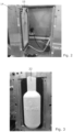
- Figures 2 and 3 show, pictorially, the appearance of a two-part mould block 14 that houses a porous mould 15 insert according to the invention. Channels through block 14 communicate with a rear side of the porous mould 15 to provide a path for suspending liquid drawn through the mould via line 18, and also reverse flow during the cleaning step (described below).
- Demoulding occurs at the step (and shown in Figure 3 ) where mould tool 15 opens for removal of a self-supporting article 22.
- a cleaning step 23 is performed to remove small fibres and maintain tool porosity/permeability.
- a high-pressure jet firing radially is inserted into the moulding chamber while the tool is open. This dislodges fibres on the surface.
- water from tank 17 is pressurised through the back of the tool 15 to dislodge entrapped fibres. Water may be drained for recycling back to an upstream step of the system. It is noteworthy that cleaning is an important step for conditioning the tool for re-use. The tool may appear visibly clean after removal of the article, but its performance will be compromised without a cleaning step.
- the self-supporting article 22 may be transported for further processing, drying etc, but such details are outside the scope of the present disclosure.
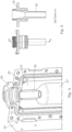
- FIG. 4 illustrates an upper portion of mould casing 14 and porous tool 15. It will be apparent that casing 14 includes a channel 24 for accommodating a seal and a fill tube 25 extends from a tool plug 26 to close off an opening into tool 15. The length of tube 25 is sufficient to extend into the substantive open volume of mould cavity 27, i.e. proximate a shoulder area of the article.
- Tube 25 overcomes issues with regard to deposition of pulp material around the neck; e.g. without this fill tube, the pulp neck may be ill-formed as it can wash away by incoming suspension. It will be apparent that tube 25 provides a hard external surface against which pulp can pack and form a neck region of the formed article. An internal surface of the bottle neck is pressed against the external surface of tube 25.
- Figure 5 shows internal detail of plug 26 and tube 25, which may include a thread for coupling to the fibre suspension delivery line 16.
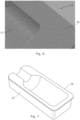
- the surface structure of a tool 15, e.g. made by additive manufacturing, is illustrated by Figure 6 .
- the image shows application of a 3D printer software 'slicer' that creates holes in the tooling.
- the porous surface is comprised of a criss-cross structure resembling a relatively consistent mesh.
- the tool 15 includes a cut-away cavity 27 which provides a negative image against which the article walls take their shape. Porosity and permeability should be generally consistent across the cavity.
- the interior surface 28 of the mould tool 15 as shown, i.e. the surface in direct contact with the forming article has, according to the present embodiment, a relatively high density of pores.
- This high detail layer 28 serves as a first zone of tool 15 and, in the illustrated example, is 5mm thick around the entire outer body of the bottle.
- Figure 7 zooms out from the image of Figure 6 to show a second zone 29 that surrounds the first zone 28.
- the second zone 29 is a lower pore density support layer that prevents the structure immediately in contact with the article from breaking due to bladder inflation (19).
- the first/inner layer 28 is typically 40% - 70% porous and the second/outer layer 29 has a typical porosity of 80-90% so that suspension liquid can be quickly pumped out of the mould from the fibre deposited against cavity 27.
- the illustrated embodiment is preferred in order to achieve desirable results in the moulded article.
- the principles of providing an additive manufactured mould (insert 14) with different zones of porosity can be adapted.
- a mixture of high- and lowdensity areas may be in contact with the article during moulding to give different surface effects.
- Three or more zones may be found to optimise the process in some future embodiments.
- the porosity may transition from a first porosity at the cavity/inlet surface to a second porosity at the outlet surface.
- Figure 8 is a cross section view of the half-mould shown in Figure 7 .
- the high-density zone 28 is clearly seen as a layer against second zone 29 that forms the substantive volume of tool insert 15.
- Layer 28 includes a lip 30 that forms a flange at edges where two halves of tool 15 meet.
- alternative configurations are possible such as where layer 28 is contained wholly within cavity 27.
- Figure 9 shows, in greater detail, a 3D printed textured porous surface of a bottle neck.
- Tool 15 may include a neck insert associated with a closure of the moulded article.
- a neck insert associated with a closure of the moulded article.
- a ring structure may be separately formed from pulp fibre by a compression moulding process and inserted into the mould to serve as a finishing step for the mouth of a bottle 22, preferably providing a flat surface 39 onto which a heat-sealed film can be applied.
- such options are not illustrated.
- the invention can generally be considered a mould (14) for forming an article from a fibre suspension.
- the mould includes an porous insert with a cavity (27) in the negative shape of an article to be formed and two regions of different porosity (28, 29) about the cavity (27).
- the mould communicates a suspending fluid of the fibre suspension, e.g. by vacuum pump, through the at least two regions of different porosity about the cavity leaving behind a formed shape on the cavity.
Landscapes
- Engineering & Computer Science (AREA)
- Manufacturing & Machinery (AREA)
- Mechanical Engineering (AREA)
- Paper (AREA)
- Moulds For Moulding Plastics Or The Like (AREA)
- Dry Formation Of Fiberboard And The Like (AREA)
- Adornments (AREA)
- Food-Manufacturing Devices (AREA)
- Diaphragms For Electromechanical Transducers (AREA)
- Details Of Rigid Or Semi-Rigid Containers (AREA)
- Application Of Or Painting With Fluid Materials (AREA)
- Containers And Packaging Bodies Having A Special Means To Remove Contents (AREA)
- Telephone Function (AREA)
- Containers Having Bodies Formed In One Piece (AREA)
- Nonwoven Fabrics (AREA)
- Casting Or Compression Moulding Of Plastics Or The Like (AREA)
- Moulding By Coating Moulds (AREA)
- General Preparation And Processing Of Foods (AREA)
Description
- The present invention relates to a mould for use in a system for forming a moulded article. Particularly, the invention is concerned with forming containers from a fibre suspension, e.g. paper pulp. The articles/containers may be a consumer packaging useful for holding liquids.
- It is desirable to reduce plastics use in consumable items, particularly packaging. Trays and simple shapes are commonly made from paper pulp, but more complex three-dimensional forms, such as bottles required to hold liquids, are more difficult to engineer.
- Published patent documents
EP1081285A1 ,EP1195466A1 ,EP2198088A1 andWO2018020219A1 each describe forming an article from paper pulp in a mould. The mould features a negative image/impression of the article and has openings through it or is porous such that a suspending liquid introduced to the mould, with which the pulp is mixed, can be removed by applying suction. The pulp left behind after the liquid is removed conforms to the shape of mould. In a second step an inflatable member in a collapsed state is introduced into the mould and inflated to apply pressure against the internal walls of the article being formed, thereby distributing pulp to a more uniform wall thickness and expelling further suspending liquid from the article and mould. The formed article is released from the mould and dried to remove remaining liquid. - The present invention is concerned with an evolution of the above-described technology to improve the specifications of the resultant article being formed or at least provide the public with an alternative. The invention is particularly suited to producing bottles for holding liquids such as cleaning products and beverages.
- According to the invention there is provided a mould as defined in claim 1 and a method as defined in claim 9.
- Other useful features are outlined in dependent claims.
- It is envisaged that the invention will ultimately produce an improved pulp bottle construction, made in one piece. Accordingly, a novel bottle obtainable by the process is also envisaged. The process herein is primarily intended for forming a bottle shaped article, which also encompasses a jar or similarly shaped lid closable container.
- The mould of the invention features a substantive volume with at least two zones of porosity. For example, a first porous (or permeable) zone located at an article facing surface of the mould may have a high density (i.e. less total free space and less permeability in its volume) and a second zone, in communication with the first zone but spaced from contact with the article, may have a lower density (i.e. greater free space than the first zone and greater permeability in its volume). Each zone has a generally continuous porosity through its volume. A third and subsequent zones may be in communication with the at least two porous zones. Furthermore, the invention is embodied by the first porous area located in contact with the article during moulding, and the second porous area distant from the first porous area, where the porosity changes over the volume of the mould. In other words, the mould defines a transitional volume between a first and second porosity.
- In one form the invention is embodied by a mould for forming a bottle-shaped article from a fibre suspension, the mould comprising: a cavity in a negative shape of the bottle-shaped article to be formed; wherein the mould is configured to communicate a suspending fluid of the fibre suspension through at least two regions of different porosity about the cavity; wherein a first porous region, having a porosity less than or equal to 90% (or preferably less than or equal to 70%), is a first layer comprising the substantive article facing surface of the cavity, and a second porous region, having a porosity greater than the first porous region, is a second layer serving as a supporting structure for the first porous region. In a particular form the mould is a 3D printed (or other form of additive manufacturing) removeable insert, that may be block-shaped, for insertion into a mould block.
- "Continuous porosity" in the context of the invention refers to a volume/surface area of consistent and evenly distributed pore structure, as distinct from a surface that has a relatively low number of intermittent "pores" or channels through the mould from an inlet side/article forming surface to an outlet side of the mould, e.g. of the type known from prior art
EP1081285A1 . Porosity between zones may be continuous in the sense that it gradually transitions from one density to another or may abruptly change at the boundary thereof. - A particular advantage of the moulding method is to allow multiple brand design options and surface features. By contrast, a conventional square carton can only be decorated by changing ink colour.
- A method associated with the invention includes preparing a fibre suspension in a suspending liquid. Preparation may involve a pulp property refiner such as a valley beater and a tank for hydrating with a shear or paddle mixer. This step may be done continuously with the process or in batches. A concentrated form of the suspension may be prepared for dilution just prior to moulding. The concentration most effective for delivery to the mould is expected to be less than 1%, e.g. approximately 0.7% fibre.
- While continuously fed to a two (or more)-part porous mould according to the invention (e.g. configured with a negative 3D image of the desired moulded article, such as a bottle) to a predetermined volume, the suspending liquid is removed via pores of the porous mould, e.g. by vacuum pressure/pump, differential or positive pressure. The predetermined volume may be monitored by weighing suspending liquid removed from the mould. By way of example, 10-50 Litres of process water may have been collected in a tank outside the porous mould, leaving behind the pulp fibres on the mould surface.
- After substantially all suspending liquid is removed, a pressurising means, e.g. an impermeable surface (such as an inflatable bladder in a collapsed state) may be applied to the moulded article to impart pressure to internal walls of the article (e.g. by inflation with pneumatic or hydraulic pressure; air, water or oil) and thereby expel further suspending liquid through pores of the porous mould. The moulded article is removed for drying.
- The walls of the porous/permeable mould are preferably cleaned after removal of the article, e.g. by reversing expelled suspending liquid back through the mould and/or use of a water jet against walls of the mould. Cleaning removes residual fibres from the porous surface and re-conditions the mould for repeated use. Particularly, permeability of the mould is restored, which is otherwise compromised after use.
- A drying stage of the method/system may utilise microwave energy, e.g. in a continuous or batch delivery system. The article may be dried at a stage either before or after the nonporous mould, or both.
- A coating stage may apply a protective layer to a surface of the moulded article. For example, the coating step may comprise spraying a base and sides of the moulded article internally and/or externally.
- A closure element may be applied to an opening of the moulded article after coating/drying. The closure element may include a neck fitment with an annular feature to seal against the opening.
- The invention may be applied in a system for forming a moulded article, comprising: a source of fibre suspension in a suspending liquid; a delivery line to deliver the fibre suspension to a porous mould according to the invention; a suction pump for removing the suspending liquid via pores of the porous mould; a pressurising means (e.g. an inflatable pressing member configured to be inserted into the mould in a collapsed state and then inflated) to apply pressure to internal walls of the article.
- The mould system devised to utilise the invention is particularly beneficial because a 3D printing process (in plastics) can be utilised to fabricate the mould's porous insert. In this way, rapid prototyping and development for process improvements can be achieved. The mould can also be made using other processes, e.g. other additive manufacturing techniques.
-
-
Figure 1 illustrates a process implementing a mould according to the invention; -
Figure 2 illustrates a 3D porous mould according to the invention; -
Figure 3 illustrates a moulded article as it is removed from the 3D porous mould; -
Figure 4 illustrates a general view of the mould and a pulp dispensing nozzle; -
Figure 5 illustrates a side and section elevation view of the pulp nozzle ofFigure 4 ; -
Figure 6 illustrates a close up view of a mould surface; -
Figure 7 illustrates a perspective view of the mould; -
Figure 8 illustrates a perspective section view of the mould fromFigure 7 ; and -
Figure 9 illustrates a view of surface features of the mould. - The following description presents an exemplary embodiment and, together with the drawings, serves to explain principles of the invention. However, the scope of the invention is not intended to be limited to the precise details of the embodiments or exact adherence with all features and steps, since variations will be apparent to a skilled person and are deemed also to be covered by the description. Terms for components used herein should be given a broad interpretation that also encompasses equivalent functions and features. In some cases, several alternative terms (synonyms) for structural features have been provided but such terms are not intended to be exhaustive.
- Descriptive terms should also be given the broadest possible interpretation; e.g. the term "comprising" as used in this specification means "consisting at least in part of" such that interpreting each statement in this specification that includes the term "comprising", features other than that or those prefaced by the term may also be present. Related terms such as "comprise" and "comprises" are to be interpreted in the same manner. Directional terms such as "vertical", "horizontal", "up", "down", "upper" and "lower" are used for convenience of explanation usually with reference to the illustrations and are not intended to be ultimately limiting if an equivalent function can be achieved with an alternative dimension and/or direction.
- The description herein refers to embodiments with particular combinations of steps or features, however, it is envisaged that further combinations and cross-combinations of compatible steps or features between embodiments will be possible. Indeed, isolated features may function independently as an invention from other features and not necessarily require implementation as a complete combination.
- For understanding the context and use of a mould according to the invention,
Figure 1 outlines one example of a process for producing a pulp article, e.g. a bottle. The process comprises the steps of preparing a pulp suspension, introducing this to a porous mould, and expelling a suspending liquid therefrom. - At a first stage of pulp processing and storage, raw pulp fibres are rehydrated and passed between plates of a
valley beater 11. This process encourages fibrillation, i.e. the partial delamination of the cell wall, resulting in a hairy appearance of the wetted fibre surfaces. The resultant "hairs", also called fibrillations, increase the relative strength of the bond between fibres in the dry product. - During this process desired additives are used to change the structure, strength and moulding properties of the bottle and potentially reduce cost. Sizing, fillers and buffer additives can be evaluated as required.
- A concentrated form of the processed pulp can be stored in a
vat 12 until required, which reduces the total amount of storage space. - Dilution, e.g. 0.1 to 5%, less than 1%, most preferably 0.7%, solid fibre of a water-based suspension, is carried out at a mixing
station 13 just prior to moulding. Mixing at this step ensures the slurry is homogenised without changing the characteristics of the pulp. As shown, bubbles rise to the top, displacing the slurry above them and pulling the bottom level liquids upwards. - The
moulding step 14 features a tool 15 (e.g. 3D printed insert) where two or more cooperating pieces are clamped together using hydraulic rams to form a cavity in which the article will form. Slurry is top-filled into tool 15 (at an inlet tube described further below), which is in contrast to a moulding processes that submerges a mould in slurry. The pulp slurry is thereafter drawn vialine 16 under a vacuum (or positive/differential pressure) throughporous tool 15, similar to an injection moulding machine. Shot mass may be controlled by measuring (e.g. weighing) the mass/volume of water being drawn into thetank 17. Once the required mass is reached, the tool is opened to ambient air. A weight scaleplatform supporting tank 17 is visible inFigure 1 . - The suspending liquid drawn with the fibre suspension in
line 16 is water. Water drawn under vacuum throughline 18 intotank 17 is substantially free of fibres since these are left behind against the walls ofporous tool 15. By way of example, suction of suspendingliquid 18 throughmould 15 is continuous until a predetermined volume (e.g. 10 litres) of water has been collected intank 17. - The "article" within
tool 15 is, at this stage, a formed but wet shape held against the internal walls of the mould. - In order to remove further suspending liquid (water) and consolidate the 3D article shape a pressurising means is activated. In the illustrated embodiment a
collapsible bladder 19 is inserted intomould 15 to act as an internal high-pressure core structure for the tool. As mentioned, this process strengthens the wet 'embryo' bottle so that it can be handled (or transported by mechanised means) before drying and displaces water in-between the cellulose fibres, thereby increasing the efficiency of the drying process. Thebladder 19 is actuated using ahydraulic pump 20 with a cylinder that displaces a fluid inline 21 intobladder 19 to expand it and conform to the tool cavity. Fluid withinline 21 is preferably noncompressible such as water. Use of water also has the advantage that any leaking or bursting of the bladder will not introduce a new substance to the system (since the suspending liquid is already water). Any bladder failures can be quickly cleaned up. -
Figures 2 and 3 show, pictorially, the appearance of a two-part mould block 14 that houses aporous mould 15 insert according to the invention. Channels throughblock 14 communicate with a rear side of theporous mould 15 to provide a path for suspending liquid drawn through the mould vialine 18, and also reverse flow during the cleaning step (described below). - Demoulding occurs at the step (and shown in
Figure 3 ) wheremould tool 15 opens for removal of a self-supportingarticle 22. A cleaningstep 23 is performed to remove small fibres and maintain tool porosity/permeability. In the illustrated form, a high-pressure jet firing radially is inserted into the moulding chamber while the tool is open. This dislodges fibres on the surface. Alternatively, or in addition, water fromtank 17 is pressurised through the back of thetool 15 to dislodge entrapped fibres. Water may be drained for recycling back to an upstream step of the system. It is noteworthy that cleaning is an important step for conditioning the tool for re-use. The tool may appear visibly clean after removal of the article, but its performance will be compromised without a cleaning step. - The self-supporting
article 22 may be transported for further processing, drying etc, but such details are outside the scope of the present disclosure. -
Figure 4 illustrates an upper portion ofmould casing 14 andporous tool 15. It will be apparent thatcasing 14 includes achannel 24 for accommodating a seal and afill tube 25 extends from atool plug 26 to close off an opening intotool 15. The length oftube 25 is sufficient to extend into the substantive open volume ofmould cavity 27, i.e. proximate a shoulder area of the article. -
Tube 25 overcomes issues with regard to deposition of pulp material around the neck; e.g. without this fill tube, the pulp neck may be ill-formed as it can wash away by incoming suspension. It will be apparent thattube 25 provides a hard external surface against which pulp can pack and form a neck region of the formed article. An internal surface of the bottle neck is pressed against the external surface oftube 25. -
Figure 5 shows internal detail ofplug 26 andtube 25, which may include a thread for coupling to the fibresuspension delivery line 16. - The surface structure of a
tool 15, e.g. made by additive manufacturing, is illustrated byFigure 6 . The image shows application of a 3D printer software 'slicer' that creates holes in the tooling. The porous surface is comprised of a criss-cross structure resembling a relatively consistent mesh. Thetool 15 includes a cut-away cavity 27 which provides a negative image against which the article walls take their shape. Porosity and permeability should be generally consistent across the cavity. - The
interior surface 28 of themould tool 15 as shown, i.e. the surface in direct contact with the forming article has, according to the present embodiment, a relatively high density of pores. - This
high detail layer 28 serves as a first zone oftool 15 and, in the illustrated example, is 5mm thick around the entire outer body of the bottle. -
Figure 7 zooms out from the image ofFigure 6 to show asecond zone 29 that surrounds thefirst zone 28. Thesecond zone 29 is a lower pore density support layer that prevents the structure immediately in contact with the article from breaking due to bladder inflation (19). - The first/
inner layer 28 is typically 40% - 70% porous and the second/outer layer 29 has a typical porosity of 80-90% so that suspension liquid can be quickly pumped out of the mould from the fibre deposited againstcavity 27. - The illustrated embodiment is preferred in order to achieve desirable results in the moulded article. However, the principles of providing an additive manufactured mould (insert 14) with different zones of porosity can be adapted. For example, a mixture of high- and lowdensity areas may be in contact with the article during moulding to give different surface effects. Three or more zones may be found to optimise the process in some future embodiments. Furthermore, assuming good control over 3D printing, the porosity may transition from a first porosity at the cavity/inlet surface to a second porosity at the outlet surface.
-
Figure 8 is a cross section view of the half-mould shown inFigure 7 . The high-density zone 28 is clearly seen as a layer againstsecond zone 29 that forms the substantive volume oftool insert 15.Layer 28 includes alip 30 that forms a flange at edges where two halves oftool 15 meet. However, alternative configurations are possible such as wherelayer 28 is contained wholly withincavity 27. Furthermore, there may be multiple cavities within a mould half to produce more than one bottle simultaneously from the same mould tool. -
Figure 9 shows, in greater detail, a 3D printed textured porous surface of a bottle neck. -
Tool 15 may include a neck insert associated with a closure of the moulded article. For example, a ring structure may be separately formed from pulp fibre by a compression moulding process and inserted into the mould to serve as a finishing step for the mouth of abottle 22, preferably providing a flat surface 39 onto which a heat-sealed film can be applied. However, such options are not illustrated. - In summary, the invention can generally be considered a mould (14) for forming an article from a fibre suspension. The mould includes an porous insert with a cavity (27) in the negative shape of an article to be formed and two regions of different porosity (28, 29) about the cavity (27). In use the mould communicates a suspending fluid of the fibre suspension, e.g. by vacuum pump, through the at least two regions of different porosity about the cavity leaving behind a formed shape on the cavity.
Claims (12)
- A mould (15) for forming a bottle shaped article (22) from a fibre suspension, the mould (15) comprising:a cavity (27) in a negative shape of the bottle shaped article (22) to be formed;wherein the mould (15) is configured to communicate a suspending fluid of the fibre suspension through at least two regions of different porosity about the cavity;wherein a first porous region (28), having a porosity less than or equal to 90%, is a first layer comprising the substantive article facing surface of the cavity (27), and a second porous region (29), having a porosity greater than the first porous region (28), is a second layer serving as a supporting structure for the first porous region.
- The mould (15) of claim 1, comprising a third porous region.
- The mould (15) of any preceding claim, wherein the mould (15) is a removeable insert for insertion into a mould block (14).
- The mould (15) of claim 3, wherein the removeable insert (15) is 3-D printed or made by another additive manufacturing technique.
- The mould (15) of claim 1, wherein a first porosity is 40%-70% and a second porosity is 80-90%.
- The mould (15) of any preceding claim, wherein the mould (15) comprises two or more cooperating pieces, each including a portion of the cavity (27), configured to open apart for removal of a moulded article (22).
- The mould (15) of any preceding claim, comprising an opening into the cavity (27) for receiving a fibre suspension dispenser nozzle.
- The mould (15) of claim 7, in combination with a fibre suspension dispenser nozzle, wherein the cavity (27) is configured for moulding a bottle comprising a neck, shoulder and main body; the fibre suspension dispenser nozzle comprising a tube (25) extendable through the opening, to a position proximate the shoulder.
- A method of moulding an article (22), comprising:preparing a fibre suspension in a suspending liquid;feeding the fibre suspension to a mould (15) according to any preceding claim;removing the suspending liquid through the at least two regions of different porosity (28, 29);applying pressure to internal walls of the article (22), in order to expel further suspending liquid through the at least two regions of different porosity (28, 29); andremoving the moulded article (22) from the mould (15).
- The method of claim 9, comprising cleaning walls of the mould (15) after removal of the article (22).
- The method of claim 10, wherein cleaning comprises reversing expelled suspending liquid back through the mould (15) and/or use of a water jet against walls of the mould (15).
- The method of any preceding claim 9 to 11, wherein the fibre suspension fed to the porous mould (15) comprises 0.1 to 1% solids, preferably 0.7% solids.
Priority Applications (2)
| Application Number | Priority Date | Filing Date | Title |
|---|---|---|---|
| EP24204680.3A EP4497871A3 (en) | 2020-11-04 | 2021-11-04 | A mould for forming a unitary article from pulp |
| HRP20241404TT HRP20241404T1 (en) | 2020-11-04 | 2021-11-04 | MOULD FOR SHAPING A UNIQUE PULP ITEM |
Applications Claiming Priority (3)
| Application Number | Priority Date | Filing Date | Title |
|---|---|---|---|
| GB2017432.2A GB2600700B (en) | 2020-11-04 | 2020-11-04 | A system and method for forming a moulded article |
| GB2019305.8A GB2600780B (en) | 2020-11-04 | 2020-12-08 | A mould for forming a unitary article from pulp |
| PCT/GB2021/052864 WO2022096888A1 (en) | 2020-11-04 | 2021-11-04 | A mould for forming a unitary article from pulp |
Related Child Applications (1)
| Application Number | Title | Priority Date | Filing Date |
|---|---|---|---|
| EP24204680.3A Division EP4497871A3 (en) | 2020-11-04 | 2021-11-04 | A mould for forming a unitary article from pulp |
Publications (2)
| Publication Number | Publication Date |
|---|---|
| EP4240908A1 EP4240908A1 (en) | 2023-09-13 |
| EP4240908B1 true EP4240908B1 (en) | 2024-10-09 |
Family
ID=73776431
Family Applications (3)
| Application Number | Title | Priority Date | Filing Date |
|---|---|---|---|
| EP21811119.3A Pending EP4240907A1 (en) | 2020-11-04 | 2021-11-04 | A system and method for forming a moulded article |
| EP24204680.3A Pending EP4497871A3 (en) | 2020-11-04 | 2021-11-04 | A mould for forming a unitary article from pulp |
| EP21811433.8A Active EP4240908B1 (en) | 2020-11-04 | 2021-11-04 | A mould for forming a unitary article from pulp |
Family Applications Before (2)
| Application Number | Title | Priority Date | Filing Date |
|---|---|---|---|
| EP21811119.3A Pending EP4240907A1 (en) | 2020-11-04 | 2021-11-04 | A system and method for forming a moulded article |
| EP24204680.3A Pending EP4497871A3 (en) | 2020-11-04 | 2021-11-04 | A mould for forming a unitary article from pulp |
Country Status (20)
| Country | Link |
|---|---|
| US (2) | US12473695B2 (en) |
| EP (3) | EP4240907A1 (en) |
| JP (2) | JP2024503777A (en) |
| KR (2) | KR20230112623A (en) |
| CN (2) | CN116802357A (en) |
| AU (2) | AU2021374875A1 (en) |
| CA (2) | CA3196795A1 (en) |
| CL (2) | CL2023001264A1 (en) |
| CO (2) | CO2023005676A2 (en) |
| DK (1) | DK4240908T3 (en) |
| ES (1) | ES2999544T3 (en) |
| FI (1) | FI4240908T3 (en) |
| GB (7) | GB2600700B (en) |
| HR (1) | HRP20241404T1 (en) |
| IL (2) | IL302418A (en) |
| MX (2) | MX2023004723A (en) |
| PE (2) | PE20240057A1 (en) |
| PL (1) | PL4240908T3 (en) |
| WO (2) | WO2022096887A1 (en) |
| ZA (1) | ZA202304914B (en) |
Families Citing this family (22)
| Publication number | Priority date | Publication date | Assignee | Title |
|---|---|---|---|---|
| SE543042C2 (en) * | 2019-01-03 | 2020-09-29 | Celwise Ab | Tool and method for producing a 3D molded pulp product |
| US20240218597A1 (en) * | 2019-10-14 | 2024-07-04 | Kiefel Gmbh | Mold body for a pre-pressing tool, and pre-pressing tool |
| US20240218606A1 (en) * | 2019-10-14 | 2024-07-04 | Kiefel Gmbh | Mold body with integrated connection unit for a pre-pressing tool, and pre-pressing tool |
| US20240218607A1 (en) * | 2019-10-14 | 2024-07-04 | Kiefel Gmbh | Mold body with varying thickness for a pre-pressing tool, and pre-pressing tool |
| GB2592452B (en) * | 2020-07-28 | 2023-05-24 | Frugalpac Ltd | Apparatus for manufacturing a container |
| GB2600700B (en) * | 2020-11-04 | 2023-07-12 | Diageo Great Britain Ltd | A system and method for forming a moulded article |
| GB2617200B (en) * | 2022-04-01 | 2024-06-12 | Pulpex Ltd | A receptacle mould and a method of manufacturing a receptacle mould |
| DE102022121491A1 (en) | 2022-08-25 | 2024-03-07 | Krones Aktiengesellschaft | Method for producing a container and an apparatus for carrying out the method |
| DE102022121462A1 (en) * | 2022-08-25 | 2024-03-07 | Krones Aktiengesellschaft | Method for producing a container comprising fibers and apparatus for carrying out the method |
| DE102022124327B4 (en) * | 2022-09-22 | 2025-12-18 | Kiefel Gmbh | Cleaning system and cleaning process, as well as manufacturing equipment for workpieces |
| TW202428429A (en) * | 2022-09-27 | 2024-07-16 | 瑞典商普勒帕克公司 | Method for dry-forming a cellulose product and product forming unit for dry-forming a cellulose product |
| US20240367079A1 (en) * | 2023-05-02 | 2024-11-07 | Koslow Technologies Corporation | Water Filter and Medium Therefor |
| GB2631421B (en) * | 2023-06-29 | 2025-09-03 | Pulpex Ltd | Transfer device |
| GB2631423B (en) * | 2023-06-29 | 2026-04-22 | Pulpex Ltd | A hollow moulded fibre product transfer mechanism and associated method |
| GB2631417A (en) * | 2023-06-29 | 2025-01-08 | Pulpex Ltd | A station and method |
| GB2631419B (en) * | 2023-06-29 | 2025-08-06 | Pulpex Ltd | A station and method |
| GB2626623B (en) * | 2023-06-29 | 2025-08-06 | Pulpex Ltd | Mould system |
| FR3158257A1 (en) * | 2024-01-12 | 2025-07-18 | Centre Technique Industriel De La Plasturgie Et Des Composites | Porous mold for the injection of natural fibers in suspension |
| WO2025163045A1 (en) | 2024-02-02 | 2025-08-07 | PAPACKS SALES GmbH | Multipart molds and three-dimensional pulp articles molded therefrom |
| US12146268B1 (en) | 2024-02-02 | 2024-11-19 | PAPACKS SALES GmbH | Multipart molds and three-dimensional pulp articles molded therefrom |
| FI20245450A1 (en) * | 2024-04-10 | 2025-10-11 | Valmet Technologies Oy | Mold for manufacturing of a molded fiber product |
| GB2642330A (en) | 2024-07-03 | 2026-01-07 | Diageo Great Britain Ltd | A package |
Citations (10)
| Publication number | Priority date | Publication date | Assignee | Title |
|---|---|---|---|---|
| JP2001140200A (en) | 1999-11-12 | 2001-05-22 | Kao Corp | Method for producing pulp molded article |
| KR20020028926A (en) | 2002-01-10 | 2002-04-17 | 김휘주 | A Process Preparing Pulp Molded Bottle Foaming |
| US6468398B1 (en) | 1998-02-23 | 2002-10-22 | Kao Corporation | Method of manufacturing pulp molded product |
| WO2006057610A2 (en) | 2004-11-26 | 2006-06-01 | Pakit International Trading Company Inc | A method and a machine for making fibre products from stock and a new type of fibre product |
| WO2009034344A2 (en) | 2007-09-14 | 2009-03-19 | Natural Resources (2000) Limited | Moulding of articles |
| DE102008008968A1 (en) | 2008-02-13 | 2009-08-20 | Schlickenrieder, Klaus, Dr. Ing. | Paper mold i.e. press mold, for manufacturing glass and plastic parts, has layer made of rough porous or foamed sintered ceramic material whose porosity is larger than porosity of fine pored layer |
| WO2016055073A1 (en) | 2014-10-08 | 2016-04-14 | Ecoxpac A/S | A system and a method for producing a molded article, such as a bottle |
| WO2018020219A1 (en) | 2016-07-26 | 2018-02-01 | Natural Resources (2000) Limited | Moulding of articles |
| WO2020141208A1 (en) | 2019-01-03 | 2020-07-09 | Celwise Ab | Tool and method for producing a 3d molded pulp product |
| WO2020182961A1 (en) | 2019-03-14 | 2020-09-17 | Danmarks Tekniske Universitet | Method of manufacturing a moulded pulp product and pulp moulding apparatus |
Family Cites Families (57)
| Publication number | Priority date | Publication date | Assignee | Title |
|---|---|---|---|---|
| CA383536A (en) * | 1939-08-22 | O. Schur Milton | Moulded waterlaid fibre article manufacture | |
| GB326305A (en) * | 1928-11-24 | 1930-03-13 | Pulp Ind Ltd | Improvements in and relating to the manufacture of hollow bodies from fibrous pulp |
| US2390457A (en) * | 1942-05-07 | 1945-12-04 | Continental Can Co | Apparatus for spraying container parts |
| US2927044A (en) * | 1956-03-05 | 1960-03-01 | Minimax Ltd | Method and apparatus for spray coating the interior of hollow articles |
| US3235455A (en) * | 1962-02-09 | 1966-02-15 | Procter & Gamble | Synergistic antibacterial compositions |
| SU818663A1 (en) * | 1979-05-11 | 1981-04-07 | Горьковский Автомобильный Завод(Производственное Объединение"Газ") | Apparatus for painting article inner surface |
| US4606942A (en) * | 1984-12-21 | 1986-08-19 | Adolph Coors Company | Spray coating apparatus |
| DE3735751A1 (en) * | 1987-10-22 | 1989-05-03 | Plansee Metallwerk | HETEROPOROESES MOLDING TOOL FOR MAKING MOLDED MOLDS AND METHOD FOR THE PRODUCTION THEREOF |
| IT1238476B (en) * | 1990-02-06 | 1993-08-18 | Gaiotto Impianti Spa | MOLD FOR THE CASTING OF CERAMIC PRODUCTS |
| US5232739A (en) * | 1990-10-15 | 1993-08-03 | Ball Corporation | Dual orifice nozzle and method for internally coating containers |
| JP2836801B2 (en) * | 1992-03-06 | 1998-12-14 | 日本碍子株式会社 | Papermaking mold, papermaking method and papermaking apparatus for fiber molded product, and paper made fiber molded product |
| EP0789644B1 (en) * | 1994-11-02 | 1999-03-24 | Portec Ag | Device for conducting fluid between a chamber bounded by a solid surface and a channel, and a method of manufacturing said device |
| JPH10212700A (en) * | 1997-01-21 | 1998-08-11 | Kobayashi Seisakusho:Kk | Molded pulp sheet-making method and apparatus therefor |
| JPH11342550A (en) * | 1998-05-29 | 1999-12-14 | Kao Corp | Papermaking mold for pulp molded products |
| WO1999042660A1 (en) | 1998-02-23 | 1999-08-26 | Kao Corporation | Method of manufacturing pulp mold formed product |
| DE69938864D1 (en) | 1998-02-23 | 2008-07-17 | Kao Corp | METHOD FOR MANUFACTURING PAPER-MADE ARTICLES |
| JP3122408B2 (en) * | 1998-02-23 | 2001-01-09 | 花王株式会社 | Method of manufacturing pulp molded product |
| JP2000027099A (en) * | 1998-07-03 | 2000-01-25 | Oji Paper Co Ltd | Manufacturing method of uneven molded body |
| DE60045819D1 (en) * | 1999-01-29 | 2011-05-19 | Kao Corp | METHOD FOR PRODUCING A FIBER FORM AND DEVICE THEREFOR |
| JP2001055697A (en) * | 1999-08-06 | 2001-02-27 | Kao Corp | Method for producing pulp molded article |
| US7048975B1 (en) * | 1999-10-15 | 2006-05-23 | Kao Corporation | Pulp molded container |
| JP3960723B2 (en) * | 1999-11-10 | 2007-08-15 | 花王株式会社 | Method for producing pulp molded article |
| JP2001137752A (en) * | 1999-11-16 | 2001-05-22 | Tokyo Gas Co Ltd | Rehabilitation repair method for existing pipeline |
| DE60033358T2 (en) * | 1999-11-17 | 2007-10-31 | Kao Corp. | Process for the production of fibrous molded parts |
| JP3331211B2 (en) * | 2000-03-01 | 2002-10-07 | 花王株式会社 | Pulp molded product |
| WO2001068984A1 (en) * | 2000-03-13 | 2001-09-20 | Kao Corporation | Drying mold for pulp mold formed body |
| US6918997B2 (en) * | 2000-04-18 | 2005-07-19 | Kao Corporation | Method of producing pulp moldings |
| JP2002105899A (en) * | 2000-09-29 | 2002-04-10 | Kao Corp | Papermaking container |
| JP3415607B2 (en) * | 2001-07-24 | 2003-06-09 | 花王株式会社 | Method for producing fiber molded body |
| GB2416143A (en) * | 2004-07-15 | 2006-01-18 | Glory Team Ind Ltd | An apparatus and a method of producing pulp moulded products |
| DE102005038887A1 (en) * | 2005-08-17 | 2007-03-01 | Dorst Technologies Gmbh & Co. Kg | Casting mold used as a die casting mold comprises a base layer made from firmly interlinked bulk material having a base layer permeability and a filter layer penetrating the surface of the base layer |
| SE529164C2 (en) * | 2004-11-26 | 2007-05-22 | Pakit Int Trading Co Inc | Pulp form and use of pulp form |
| JP2007292304A (en) * | 2006-03-27 | 2007-11-08 | Kurimoto Ltd | End surface closing cap for pipes |
| WO2011159240A1 (en) | 2010-06-15 | 2011-12-22 | Pakit International Trading Company Inc. | A method for applying a film on moulded fibrous product and a product produced by said method |
| FR2965491B1 (en) * | 2010-10-05 | 2013-05-17 | Sgd Sa | COATING PROCESS AND CORRESPONDING COATING MACHINE |
| EP3181471B8 (en) * | 2011-07-19 | 2019-06-26 | Lgab Llc | Biodegradable bottle for liquids |
| EP3038936B1 (en) * | 2013-10-02 | 2024-08-07 | Eco.logic Brands Inc. | Containers for particulate materials |
| EA032568B1 (en) * | 2014-04-21 | 2019-06-28 | Тоё Сэйкан Ко., Лтд. | Apparatus for applying material |
| PL3140454T3 (en) * | 2014-05-07 | 2020-06-01 | University Of Maine System Board Of Trustees | High efficiency production of nanofibrillated cellulose |
| US9932710B2 (en) * | 2014-12-12 | 2018-04-03 | Golden Arrow Printing Co., Ltd. | Porous metal mold for wet pulp molding process and method of using the same |
| HUE048430T2 (en) * | 2014-12-22 | 2020-07-28 | Celwise Ab | Method of molding a product from a pulp slurry and tool or tool part for use in such a process |
| PL3048415T3 (en) * | 2015-01-20 | 2018-03-30 | Sturm Maschinen- & Anlagenbau Gmbh | Method and coating system for coating of inner walls |
| TWI610007B (en) * | 2016-09-23 | 2018-01-01 | Paper plastic cover body and forming device thereof | |
| DE102017214469A1 (en) * | 2017-08-18 | 2019-02-21 | Sig Technology Ag | A method of manufacturing a container from a container blank, in particular by reducing a height of the container blank |
| SE543041C2 (en) * | 2018-07-19 | 2020-09-29 | Celwise Ab | Method of producing a pulp product |
| BR112022001656A2 (en) * | 2019-07-30 | 2022-03-22 | Varden Process Pty Ltd | Molded pulp fiber product, and method of forming the same |
| CN210916808U (en) * | 2019-09-25 | 2020-07-03 | 龙口市科利马工贸有限公司 | Mould and equipment for paper pulp moulding of bottle-shaped product |
| WO2021142505A1 (en) * | 2020-01-18 | 2021-07-22 | LIAO, Yun-Hsuan | Paper pulp cup lids with double lock structure and its forming method |
| EP3985170B1 (en) | 2020-10-19 | 2026-04-08 | Valmet Technologies Oy | Mold for manufacturing of a molded fiber product |
| GB2600700B (en) * | 2020-11-04 | 2023-07-12 | Diageo Great Britain Ltd | A system and method for forming a moulded article |
| CN112411264B (en) | 2020-11-24 | 2023-01-13 | 天津茂创科技发展有限公司 | Shaping device for molded fiber hollow structure product and preparation method thereof |
| SE2230069A1 (en) * | 2022-03-11 | 2023-09-12 | Stora Enso Oyj | A tool for molding a fiber-based product |
| GB2616479B (en) * | 2022-03-11 | 2024-10-16 | Pulpex Ltd | Method of and system for forming a receptacle |
| GB2617200B (en) * | 2022-04-01 | 2024-06-12 | Pulpex Ltd | A receptacle mould and a method of manufacturing a receptacle mould |
| WO2024123855A1 (en) * | 2022-12-06 | 2024-06-13 | The Procter & Gamble Company | Multi-region pulp article |
| US20240183109A1 (en) * | 2022-12-06 | 2024-06-06 | The Procter & Gamble Company | Multi-Region Pulp Article |
| GB2628131A (en) * | 2023-03-14 | 2024-09-18 | Pulpex Ltd | Moulding of hollow moulded fibre products |
-
2020
- 2020-11-04 GB GB2017432.2A patent/GB2600700B/en active Active
- 2020-12-08 GB GB2019308.2A patent/GB2600781B/en active Active
- 2020-12-08 GB GB2019305.8A patent/GB2600780B/en active Active
- 2020-12-08 GB GB2112650.3A patent/GB2600809B/en active Active
- 2020-12-08 GB GB2210013.5A patent/GB2614773A/en not_active Withdrawn
- 2020-12-08 GB GBGB2019307.4A patent/GB202019307D0/en not_active Ceased
- 2020-12-08 GB GB2210014.3A patent/GB2611848A/en not_active Withdrawn
-
2021
- 2021-11-04 CA CA3196795A patent/CA3196795A1/en active Pending
- 2021-11-04 US US18/033,406 patent/US12473695B2/en active Active
- 2021-11-04 EP EP21811119.3A patent/EP4240907A1/en active Pending
- 2021-11-04 KR KR1020237016919A patent/KR20230112623A/en active Pending
- 2021-11-04 US US18/033,238 patent/US20230340733A1/en active Pending
- 2021-11-04 MX MX2023004723A patent/MX2023004723A/en unknown
- 2021-11-04 ES ES21811433T patent/ES2999544T3/en active Active
- 2021-11-04 AU AU2021374875A patent/AU2021374875A1/en active Pending
- 2021-11-04 JP JP2023524979A patent/JP2024503777A/en active Pending
- 2021-11-04 PL PL21811433.8T patent/PL4240908T3/en unknown
- 2021-11-04 CN CN202180081349.0A patent/CN116802357A/en active Pending
- 2021-11-04 WO PCT/GB2021/052863 patent/WO2022096887A1/en not_active Ceased
- 2021-11-04 EP EP24204680.3A patent/EP4497871A3/en active Pending
- 2021-11-04 AU AU2021375390A patent/AU2021375390A1/en active Pending
- 2021-11-04 HR HRP20241404TT patent/HRP20241404T1/en unknown
- 2021-11-04 JP JP2023524760A patent/JP7772063B2/en active Active
- 2021-11-04 PE PE2023001545A patent/PE20240057A1/en unknown
- 2021-11-04 CN CN202180081911.XA patent/CN116583644A/en active Pending
- 2021-11-04 IL IL302418A patent/IL302418A/en unknown
- 2021-11-04 CA CA3196803A patent/CA3196803A1/en active Pending
- 2021-11-04 MX MX2023004753A patent/MX2023004753A/en unknown
- 2021-11-04 KR KR1020237017005A patent/KR20230112624A/en active Pending
- 2021-11-04 WO PCT/GB2021/052864 patent/WO2022096888A1/en not_active Ceased
- 2021-11-04 FI FIEP21811433.8T patent/FI4240908T3/en active
- 2021-11-04 EP EP21811433.8A patent/EP4240908B1/en active Active
- 2021-11-04 DK DK21811433.8T patent/DK4240908T3/en active
- 2021-11-04 IL IL302417A patent/IL302417A/en unknown
- 2021-11-04 PE PE2023001544A patent/PE20231807A1/en unknown
-
2023
- 2023-05-02 CL CL2023001264A patent/CL2023001264A1/en unknown
- 2023-05-02 ZA ZA2023/04914A patent/ZA202304914B/en unknown
- 2023-05-02 CL CL2023001265A patent/CL2023001265A1/en unknown
- 2023-05-03 CO CONC2023/0005676A patent/CO2023005676A2/en unknown
- 2023-05-03 CO CONC2023/0005667A patent/CO2023005667A2/en unknown
Patent Citations (10)
| Publication number | Priority date | Publication date | Assignee | Title |
|---|---|---|---|---|
| US6468398B1 (en) | 1998-02-23 | 2002-10-22 | Kao Corporation | Method of manufacturing pulp molded product |
| JP2001140200A (en) | 1999-11-12 | 2001-05-22 | Kao Corp | Method for producing pulp molded article |
| KR20020028926A (en) | 2002-01-10 | 2002-04-17 | 김휘주 | A Process Preparing Pulp Molded Bottle Foaming |
| WO2006057610A2 (en) | 2004-11-26 | 2006-06-01 | Pakit International Trading Company Inc | A method and a machine for making fibre products from stock and a new type of fibre product |
| WO2009034344A2 (en) | 2007-09-14 | 2009-03-19 | Natural Resources (2000) Limited | Moulding of articles |
| DE102008008968A1 (en) | 2008-02-13 | 2009-08-20 | Schlickenrieder, Klaus, Dr. Ing. | Paper mold i.e. press mold, for manufacturing glass and plastic parts, has layer made of rough porous or foamed sintered ceramic material whose porosity is larger than porosity of fine pored layer |
| WO2016055073A1 (en) | 2014-10-08 | 2016-04-14 | Ecoxpac A/S | A system and a method for producing a molded article, such as a bottle |
| WO2018020219A1 (en) | 2016-07-26 | 2018-02-01 | Natural Resources (2000) Limited | Moulding of articles |
| WO2020141208A1 (en) | 2019-01-03 | 2020-07-09 | Celwise Ab | Tool and method for producing a 3d molded pulp product |
| WO2020182961A1 (en) | 2019-03-14 | 2020-09-17 | Danmarks Tekniske Universitet | Method of manufacturing a moulded pulp product and pulp moulding apparatus |
Non-Patent Citations (7)
| Title |
|---|
| "Characterization of Materials, Second Edition", 12 October 2012, WILEY , article ESPINAL LAURA: "POROSITY AND ITS MEASUREMENT", pages: 1 - 9, XP055832126 |
| ANONYMOUS: "How to Calculate Perforated Metal Sheet Open Area?", BOEGGER (ACCESSED VIA THE WAYBACK MACHINE), 30 July 2019 (2019-07-30), XP093297158, Retrieved from the Internet <URL: https://web.archive.org/web/20190730050417/https://www.perforated-sheet.com/calculation/how-to-calculate-open-area.html> |
| ANONYMOUS: "Hydraulic conductivity", WIKIPEDIA (ACCESSED VIA THE WAYBACK MACHINE), 1 March 2019 (2019-03-01), XP093297148, Retrieved from the Internet <URL: https://web.archive.org/web/20190301085726/https://en.wikipedia.org/wiki/Hydraulic_conductivity> |
| ANONYMOUS: "Porosity", WIKIPEDIA (ACCESSED VIA THE WAYBACK MACHINE), 10 November 2020 (2020-11-10), XP093297142, Retrieved from the Internet <URL:https://web.archive.org/web/20201101020755/https://en.wikipedia.org/wiki/Porosity> |
| D4b - "Mastering The Calculation Of Mesh Open Area Percentage In Woven Wire Mesh" The mesh company, Query 27 May 2025 (no date at all on website) |
| RICHARD C. SELLEY, STEPHEN A. SONNENBERG: "Elements of Petroleum Geology (Third Edition)", 1 January 2015, ACADEMIC PRESS, ISBN: 978-0-12-386031-6, article RICHARD C. SELLEY AND STEPHEN, A. SONNENBERG: "Chapter 6.1 Porosity", pages: 1 - 12, XP009562149 |
| TAIWAN PULP MOLDING CO., LTD.: "TPM-1500 Introduction | Taiwan Pulp Molding Co., Ltd.", 15 January 2019 (2019-01-15), XP093297162, Retrieved from the Internet <URL:https://www.youtube.com/watch?v=maVSJ0c6Pp4> |
Also Published As
Similar Documents
| Publication | Publication Date | Title |
|---|---|---|
| EP4240908B1 (en) | A mould for forming a unitary article from pulp | |
| AU2023232472B2 (en) | Method of and system for forming a receptacle | |
| US20260015801A1 (en) | Moulding of hollow moulded fibre products | |
| US20250012016A1 (en) | Receptacle mould and a method of manufacturing a receptacle mould | |
| HK40074907A (en) | A mould for forming a unitary article from pulp | |
| HK40074094A (en) | A system and method for forming a moulded article | |
| US20250137204A1 (en) | Method and system for forming a receptacle | |
| GB2622789A (en) | System for and method of forming receptacle | |
| CN121368660A (en) | Mold section and molding station | |
| CN121358918A (en) | Molding of hollow fiber products |
Legal Events
| Date | Code | Title | Description |
|---|---|---|---|
| REG | Reference to a national code |
Ref country code: HR Ref legal event code: TUEP Ref document number: P20241404T Country of ref document: HR |
|
| STAA | Information on the status of an ep patent application or granted ep patent |
Free format text: STATUS: UNKNOWN |
|
| STAA | Information on the status of an ep patent application or granted ep patent |
Free format text: STATUS: THE INTERNATIONAL PUBLICATION HAS BEEN MADE |
|
| PUAI | Public reference made under article 153(3) epc to a published international application that has entered the european phase |
Free format text: ORIGINAL CODE: 0009012 |
|
| STAA | Information on the status of an ep patent application or granted ep patent |
Free format text: STATUS: REQUEST FOR EXAMINATION WAS MADE |
|
| 17P | Request for examination filed |
Effective date: 20230427 |
|
| AK | Designated contracting states |
Kind code of ref document: A1 Designated state(s): AL AT BE BG CH CY CZ DE DK EE ES FI FR GB GR HR HU IE IS IT LI LT LU LV MC MK MT NL NO PL PT RO RS SE SI SK SM TR |
|
| DAV | Request for validation of the european patent (deleted) | ||
| DAX | Request for extension of the european patent (deleted) | ||
| GRAP | Despatch of communication of intention to grant a patent |
Free format text: ORIGINAL CODE: EPIDOSNIGR1 |
|
| STAA | Information on the status of an ep patent application or granted ep patent |
Free format text: STATUS: GRANT OF PATENT IS INTENDED |
|
| RIC1 | Information provided on ipc code assigned before grant |
Ipc: D21J 3/10 20060101ALI20240610BHEP Ipc: D21J 7/00 20060101AFI20240610BHEP |
|
| INTG | Intention to grant announced |
Effective date: 20240701 |
|
| GRAS | Grant fee paid |
Free format text: ORIGINAL CODE: EPIDOSNIGR3 |
|
| GRAA | (expected) grant |
Free format text: ORIGINAL CODE: 0009210 |
|
| STAA | Information on the status of an ep patent application or granted ep patent |
Free format text: STATUS: THE PATENT HAS BEEN GRANTED |
|
| TPAC | Observations filed by third parties |
Free format text: ORIGINAL CODE: EPIDOSNTIPA |
|
| AK | Designated contracting states |
Kind code of ref document: B1 Designated state(s): AL AT BE BG CH CY CZ DE DK EE ES FI FR GB GR HR HU IE IS IT LI LT LU LV MC MK MT NL NO PL PT RO RS SE SI SK SM TR |
|
| REG | Reference to a national code |
Ref country code: CH Ref legal event code: EP |
|
| REG | Reference to a national code |
Ref country code: DE Ref legal event code: R096 Ref document number: 602021020088 Country of ref document: DE |
|
| REG | Reference to a national code |
Ref country code: IE Ref legal event code: FG4D |
|
| REG | Reference to a national code |
Ref country code: FI Ref legal event code: FGE |
|
| P01 | Opt-out of the competence of the unified patent court (upc) registered |
Free format text: CASE NUMBER: APP_52972/2024 Effective date: 20240923 |
|
| REG | Reference to a national code |
Ref country code: DK Ref legal event code: T3 Effective date: 20241111 |
|
| REG | Reference to a national code |
Ref country code: SE Ref legal event code: TRGR |
|
| REG | Reference to a national code |
Ref country code: HR Ref legal event code: ODRP Ref document number: P20241404T Country of ref document: HR Payment date: 20241122 Year of fee payment: 4 |
|
| REG | Reference to a national code |
Ref country code: NL Ref legal event code: FP |
|
| REG | Reference to a national code |
Ref country code: HR Ref legal event code: T1PR Ref document number: P20241404 Country of ref document: HR |
|
| REG | Reference to a national code |
Ref country code: LT Ref legal event code: MG9D |
|
| REG | Reference to a national code |
Ref country code: ES Ref legal event code: FG2A Ref document number: 2999544 Country of ref document: ES Kind code of ref document: T3 Effective date: 20250226 |
|
| PG25 | Lapsed in a contracting state [announced via postgrant information from national office to epo] |
Ref country code: IS Free format text: LAPSE BECAUSE OF FAILURE TO SUBMIT A TRANSLATION OF THE DESCRIPTION OR TO PAY THE FEE WITHIN THE PRESCRIBED TIME-LIMIT Effective date: 20250209 Ref country code: PT Free format text: LAPSE BECAUSE OF FAILURE TO SUBMIT A TRANSLATION OF THE DESCRIPTION OR TO PAY THE FEE WITHIN THE PRESCRIBED TIME-LIMIT Effective date: 20250210 |
|
| PG25 | Lapsed in a contracting state [announced via postgrant information from national office to epo] |
Ref country code: BG Free format text: LAPSE BECAUSE OF FAILURE TO SUBMIT A TRANSLATION OF THE DESCRIPTION OR TO PAY THE FEE WITHIN THE PRESCRIBED TIME-LIMIT Effective date: 20241009 |
|
| PG25 | Lapsed in a contracting state [announced via postgrant information from national office to epo] |
Ref country code: LV Free format text: LAPSE BECAUSE OF FAILURE TO SUBMIT A TRANSLATION OF THE DESCRIPTION OR TO PAY THE FEE WITHIN THE PRESCRIBED TIME-LIMIT Effective date: 20241009 Ref country code: GR Free format text: LAPSE BECAUSE OF FAILURE TO SUBMIT A TRANSLATION OF THE DESCRIPTION OR TO PAY THE FEE WITHIN THE PRESCRIBED TIME-LIMIT Effective date: 20250110 |
|
| PG25 | Lapsed in a contracting state [announced via postgrant information from national office to epo] |
Ref country code: RS Free format text: LAPSE BECAUSE OF FAILURE TO SUBMIT A TRANSLATION OF THE DESCRIPTION OR TO PAY THE FEE WITHIN THE PRESCRIBED TIME-LIMIT Effective date: 20250109 |
|
| REG | Reference to a national code |
Ref country code: CH Ref legal event code: PL |
|
| PG25 | Lapsed in a contracting state [announced via postgrant information from national office to epo] |
Ref country code: SM Free format text: LAPSE BECAUSE OF FAILURE TO SUBMIT A TRANSLATION OF THE DESCRIPTION OR TO PAY THE FEE WITHIN THE PRESCRIBED TIME-LIMIT Effective date: 20241009 |
|
| PG25 | Lapsed in a contracting state [announced via postgrant information from national office to epo] |
Ref country code: MC Free format text: LAPSE BECAUSE OF FAILURE TO SUBMIT A TRANSLATION OF THE DESCRIPTION OR TO PAY THE FEE WITHIN THE PRESCRIBED TIME-LIMIT Effective date: 20241009 |
|
| REG | Reference to a national code |
Ref country code: DE Ref legal event code: R026 Ref document number: 602021020088 Country of ref document: DE |
|
| PLBI | Opposition filed |
Free format text: ORIGINAL CODE: 0009260 |
|
| PG25 | Lapsed in a contracting state [announced via postgrant information from national office to epo] |
Ref country code: LU Free format text: LAPSE BECAUSE OF NON-PAYMENT OF DUE FEES Effective date: 20241104 |
|
| REG | Reference to a national code |
Ref country code: CH Ref legal event code: PL |
|
| PG25 | Lapsed in a contracting state [announced via postgrant information from national office to epo] |
Ref country code: EE Free format text: LAPSE BECAUSE OF FAILURE TO SUBMIT A TRANSLATION OF THE DESCRIPTION OR TO PAY THE FEE WITHIN THE PRESCRIBED TIME-LIMIT Effective date: 20241009 |
|
| PG25 | Lapsed in a contracting state [announced via postgrant information from national office to epo] |
Ref country code: CH Free format text: LAPSE BECAUSE OF NON-PAYMENT OF DUE FEES Effective date: 20241130 |
|
| PLAX | Notice of opposition and request to file observation + time limit sent |
Free format text: ORIGINAL CODE: EPIDOSNOBS2 |
|
| PG25 | Lapsed in a contracting state [announced via postgrant information from national office to epo] |
Ref country code: RO Free format text: LAPSE BECAUSE OF FAILURE TO SUBMIT A TRANSLATION OF THE DESCRIPTION OR TO PAY THE FEE WITHIN THE PRESCRIBED TIME-LIMIT Effective date: 20241009 |
|
| PG25 | Lapsed in a contracting state [announced via postgrant information from national office to epo] |
Ref country code: SK Free format text: LAPSE BECAUSE OF FAILURE TO SUBMIT A TRANSLATION OF THE DESCRIPTION OR TO PAY THE FEE WITHIN THE PRESCRIBED TIME-LIMIT Effective date: 20241009 |
|
| PG25 | Lapsed in a contracting state [announced via postgrant information from national office to epo] |
Ref country code: CZ Free format text: LAPSE BECAUSE OF FAILURE TO SUBMIT A TRANSLATION OF THE DESCRIPTION OR TO PAY THE FEE WITHIN THE PRESCRIBED TIME-LIMIT Effective date: 20241009 |
|
| 26 | Opposition filed |
Opponent name: ALPLA WERKE ALWIN LEHNER GMBH & CO. KG Effective date: 20250708 |
|
| REG | Reference to a national code |
Ref country code: BE Ref legal event code: MM Effective date: 20241130 |
|
| PG25 | Lapsed in a contracting state [announced via postgrant information from national office to epo] |
Ref country code: BE Free format text: LAPSE BECAUSE OF NON-PAYMENT OF DUE FEES Effective date: 20241130 |
|
| PG25 | Lapsed in a contracting state [announced via postgrant information from national office to epo] |
Ref country code: IE Free format text: LAPSE BECAUSE OF NON-PAYMENT OF DUE FEES Effective date: 20241104 |
|
| PLBB | Reply of patent proprietor to notice(s) of opposition received |
Free format text: ORIGINAL CODE: EPIDOSNOBS3 |
|
| REG | Reference to a national code |
Ref country code: HR Ref legal event code: ODRP Ref document number: P20241404 Country of ref document: HR Payment date: 20251029 Year of fee payment: 5 |
|
| PGFP | Annual fee paid to national office [announced via postgrant information from national office to epo] |
Ref country code: NL Payment date: 20251124 Year of fee payment: 5 |
|
| PGFP | Annual fee paid to national office [announced via postgrant information from national office to epo] |
Ref country code: DE Payment date: 20251126 Year of fee payment: 5 |
|
| PGFP | Annual fee paid to national office [announced via postgrant information from national office to epo] |
Ref country code: GB Payment date: 20251024 Year of fee payment: 5 |
|
| PGFP | Annual fee paid to national office [announced via postgrant information from national office to epo] |
Ref country code: NO Payment date: 20251120 Year of fee payment: 5 |
|
| PGFP | Annual fee paid to national office [announced via postgrant information from national office to epo] |
Ref country code: AT Payment date: 20260113 Year of fee payment: 5 |
|
| PGFP | Annual fee paid to national office [announced via postgrant information from national office to epo] |
Ref country code: IT Payment date: 20251121 Year of fee payment: 5 Ref country code: FI Payment date: 20251124 Year of fee payment: 5 Ref country code: DK Payment date: 20251124 Year of fee payment: 5 |
|
| PGFP | Annual fee paid to national office [announced via postgrant information from national office to epo] |
Ref country code: HR Payment date: 20251029 Year of fee payment: 5 Ref country code: FR Payment date: 20251124 Year of fee payment: 5 |
|
| PGFP | Annual fee paid to national office [announced via postgrant information from national office to epo] |
Ref country code: TR Payment date: 20251028 Year of fee payment: 5 |
|
| PGFP | Annual fee paid to national office [announced via postgrant information from national office to epo] |
Ref country code: SE Payment date: 20251124 Year of fee payment: 5 |
|
| PGFP | Annual fee paid to national office [announced via postgrant information from national office to epo] |
Ref country code: PL Payment date: 20251028 Year of fee payment: 5 |
|
| PGFP | Annual fee paid to national office [announced via postgrant information from national office to epo] |
Ref country code: ES Payment date: 20251209 Year of fee payment: 5 |
|
| PG25 | Lapsed in a contracting state [announced via postgrant information from national office to epo] |
Ref country code: HU Free format text: LAPSE BECAUSE OF FAILURE TO SUBMIT A TRANSLATION OF THE DESCRIPTION OR TO PAY THE FEE WITHIN THE PRESCRIBED TIME-LIMIT; INVALID AB INITIO Effective date: 20211104 |
|
| PG25 | Lapsed in a contracting state [announced via postgrant information from national office to epo] |
Ref country code: CY Free format text: LAPSE BECAUSE OF FAILURE TO SUBMIT A TRANSLATION OF THE DESCRIPTION OR TO PAY THE FEE WITHIN THE PRESCRIBED TIME-LIMIT; INVALID AB INITIO Effective date: 20211104 |