EP4240682B1 - Schlauchlagereinheit zur lagerung eines schlauchs - Google Patents
Schlauchlagereinheit zur lagerung eines schlauchs Download PDFInfo
- Publication number
- EP4240682B1 EP4240682B1 EP21824320.2A EP21824320A EP4240682B1 EP 4240682 B1 EP4240682 B1 EP 4240682B1 EP 21824320 A EP21824320 A EP 21824320A EP 4240682 B1 EP4240682 B1 EP 4240682B1
- Authority
- EP
- European Patent Office
- Prior art keywords
- hose
- adaptor
- tap
- storage
- hook
- Prior art date
- Legal status (The legal status is an assumption and is not a legal conclusion. Google has not performed a legal analysis and makes no representation as to the accuracy of the status listed.)
- Active
Links
Images




Classifications
-
- B—PERFORMING OPERATIONS; TRANSPORTING
- B65—CONVEYING; PACKING; STORING; HANDLING THIN OR FILAMENTARY MATERIAL
- B65H—HANDLING THIN OR FILAMENTARY MATERIAL, e.g. SHEETS, WEBS, CABLES
- B65H75/00—Storing webs, tapes, or filamentary material, e.g. on reels
- B65H75/02—Cores, formers, supports, or holders for coiled, wound, or folded material, e.g. reels, spindles, bobbins, cop tubes, cans, mandrels or chucks
- B65H75/34—Cores, formers, supports, or holders for coiled, wound, or folded material, e.g. reels, spindles, bobbins, cop tubes, cans, mandrels or chucks specially adapted or mounted for storing and repeatedly paying-out and re-storing lengths of material provided for particular purposes, e.g. anchored hoses, power cables
- B65H75/36—Cores, formers, supports, or holders for coiled, wound, or folded material, e.g. reels, spindles, bobbins, cop tubes, cans, mandrels or chucks specially adapted or mounted for storing and repeatedly paying-out and re-storing lengths of material provided for particular purposes, e.g. anchored hoses, power cables without essentially involving the use of a core or former internal to a stored package of material, e.g. with stored material housed within casing or container, or intermittently engaging a plurality of supports as in sinuous or serpentine fashion
- B65H75/366—Cores, formers, supports, or holders for coiled, wound, or folded material, e.g. reels, spindles, bobbins, cop tubes, cans, mandrels or chucks specially adapted or mounted for storing and repeatedly paying-out and re-storing lengths of material provided for particular purposes, e.g. anchored hoses, power cables without essentially involving the use of a core or former internal to a stored package of material, e.g. with stored material housed within casing or container, or intermittently engaging a plurality of supports as in sinuous or serpentine fashion with stored package of material loosely hanging on a support, e.g. a hose hanger
-
- B—PERFORMING OPERATIONS; TRANSPORTING
- B65—CONVEYING; PACKING; STORING; HANDLING THIN OR FILAMENTARY MATERIAL
- B65H—HANDLING THIN OR FILAMENTARY MATERIAL, e.g. SHEETS, WEBS, CABLES
- B65H2701/00—Handled material; Storage means
- B65H2701/30—Handled filamentary material
- B65H2701/33—Hollow or hose-like material
Definitions
- the present invention relates to a hose storage unit for storing a hose.
- a hose storage device for storing a hose, specifically a water hose, is well-known.
- hose storage devices are generally mounted on a wall, a cabinet, and the like, which may increase components associated with the hose storage devices. This additional mounting of such components of the hose storage device may be challenging in some situations.
- the hose storage device typically includes a hose trolley or a hose box.
- the hose trolleys or the hose boxes require increased space on a floor or may have to be firmly mounted to the wall. Typically, such arrangements are not useful for short hoses. Further, the hose trolleys or the hose boxes are expensive which increase an overall cost associated with the hose storage device.
- hose storage devices have been developed for storing the water hose around a water tap.
- Such hose storage devices generally include a hose holder or hanger which is coupled to the water tap.
- hose storage device also face constraints due to involvement of a large number of components, connection joints, attachments, and the like.
- the hose holder or hanger may also put pressure on connection of the hose storage device with the tap.
- there is a need for an improved design of the hose storage device which provides a simple and cost-effective means for hose storage and can be used for different (say short) hoses.
- Korean patent 20110024876 reference discloses a fire hose hanger which includes a cylindrical rotating body at one end of a long supporting stand. Further, a tubular hanger portion is formed at other end of the support frame to hang a tubular portion. A fire hose is provided between the cylindrical rotary body and the tubular hanger portion. The fire hose hanger is mounted on a cylindrical rotary body.
- the '876 reference relies on auxiliary components such as springs, and a separation prevention ring for assembly of the coupling with the fire hose hanger and the fire hose.
- US2569857 patent reference discloses a body and a hose rack assembly.
- the body includes a fluid discharge portion and two correspondingly shaped flanges. These flanges are arranged substantially in the same plane, and each is apertured to receive a bolt member. Each bolt member extends into a wall.
- the hose rack is attached to the body via these two correspondingly shaped flanges.
- the rack is preferably formed by bending a single elongated rod intermediate its ends to form a cradle for receiving and supporting a coiled hose.
- US2111811 reference discloses a fire hose rack.
- the hose rack includes a standpipe outlet valve assembled with the wall.
- the standpipe outlet valve controls the flow of water from a standpipe through a union or a nipple.
- the nipple passes through a hole provided in the frame also supports a U-shaped frame and a hose which is in position as it will be held by spring when in place.
- the hose rack is adapted to swing in a horizontal plane about the nipple.
- the hose is secured to the nipple by means of a coupling.
- a nut is threaded to one end of the nipple and serves to support the frame.
- the frame is provided with a pin extending from one arm of the frame to the other which serves to lock the spring in the frame.
- hose holder for storing a hose at a water tap.
- the hose holder includes a connection portion for connecting a holding device with the water tap and a holding portion for receiving the hose.
- the connection portion includes a tap connection portion for mechanically and fluidly coupling the hose holder with the water tap.
- the holding portion includes a hose receiving area for supporting the coiled hose in a hanging position such that the windings of the coiled hose are arranged in a vertical plane.
- hoses having a longer length are generally heavier which may damage the tap connection portion leading to leakage or complete break-off.
- the objective is at least partially achieved by a new design of a hose storage unit for storing a hose at a tap.
- the hose storage includes a storage hook to receive the hose.
- the hose storage also includes a tap connector to fluidly connect the hose and the tap.
- the hose storage unit is characterized in that an adaptor is removably coupled with the tap and engaged with the tap connector. The adaptor fluidly couples the tap with the tap connector. Further, the storage hook is associated with the adaptor.
- the present invention provides an improved design of the hose storage uni in accordance with claim 1 which allows quick and easy installation of the hose at the tap.
- the new design of the hose storage unit can be installed in a compact space and is readily compatible. Further, the hose storage unit does not require an external structure such as a wall for mounting the hose storage units or components thereof.
- the hose storage unit includes fewer parts thus making the assembly simple and cost effective.
- the storage hook is directly connected to the adaptor which acts as a screw element. Therefore, a liquid can be fed directly into the hose through the adaptor, and the tap connector.
- a circular arrangement of the hose storage unit allows the storage hook to rotate around a central axis of the adaptor which makes the hose storage unit user friendly and provides improved ergonomics.
- the tap connector includes a sealing element that provides tightness of the hose storage unit with an existing tap.
- the hose is stored on the storage hook which is associated (or coupled) to the adaptor hence a weight of the hose is supported by the adaptor which prevents damage and breakdown at the hose connection.
- the storage hook is associated with the adaptor by coupling the storage hook around the adaptor. This may allow implementation benefits along with ease of assembly or disassembly of the storage hook with the adaptor.
- the storage hook is associated with the adaptor by fixing the storage hook with the adaptor.
- the coupling between the adaptor and the tap connector is a thread coupling.
- the coupling may be any type of coupling such as the thread coupling which provides ease in assembly and rigidity to a connection between the adaptor and the tap connector.
- the adaptor is threadably coupled with the tap.
- the thread coupling provides ease in assembly and rigidity to a connection between the adaptor and the tap, though the coupling may be any coupling such as snap-fit, press-fit or any other as used or known in the art.
- the storage hook is removably coupled around the adaptor and the tap connector.
- a removable coupling provides flexibility to use the hose storage unit for different taps thereby providing a versatile and modular hose storage unit. Further, the hose storage unit may be quickly dissembled when not in use.
- the storage hook includes a hose receiving portion to receive the hose.
- the hose receiving portion allows the user to store (say winding or looping) the hose on the storage hook.
- the hose receiving portion of the storage hook is substantially horizontal.
- the substantially horizontal hose receiving portion provides a larger and stable area for holding of the hose in a horizontal configuration.
- the hose receiving portion of the storage hook is inclined with respect to the central axis of the adaptor. Such an inclined hose receiving portion allows the hose to be stored in an inclined configuration which provides easy and secure storage of the hose.
- the storage hook has a "U” shape.
- the storage hook may have any shape (say “V”, “L” and like shapes), size, type as per application requirements.
- This arrangement i.e., the "U" shape of the present disclosure
- the storage hook may provide easy, stable, and secure storage of the hose.
- the storage hook includes a hole to receive the adaptor. This arrangement provides easy assembly of the storage hook around the adaptor and thereby with the tap.
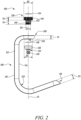
- FIG. 1 illustrates a hose storage unit 100 for storing a hose 102 (as shown in FIG. 5 ) at a tap 104 (as shown in FIG. 5 ).
- the hose storage unit 100 may be used to store hoses 102 having different lengths and types. The length and the type of the hose 102 may vary depending upon application requirements.
- the hose 102 may be used for a number of indoor and outdoor applications.
- the tap 104 may supply any type of liquid, without limiting the scope of the present invention. In the illustrated embodiment, the tap 104 supplies water. In application, water from the tap 104 may flow through the hose 102.
- the tap 104 may include any type of tap such as a wall mounted tap, a pillar tap, a mixer tap, and the like.
- the hose storage unit 100 includes a storage hook 106 to receive the hose 102.
- the storage hook 106 has a substantially C-shaped, or U-shaped structure.
- the storage hook 106 includes a first end 108, a second end 110, and a vertical portion 112.
- the vertical portion 112 extends between the first and second ends 108, 110.
- the storage hook 106 also includes a first surface 114 and a second surface 116.
- the first surface 114 and second surface 116 include a generally curved shaped profile.
- the first end 108 defines a first thickness " T1 ".
- the storage hook 106 defines a through hole 118 (as shown in FIG. 3 ) proximate the first end 108 to receive a screw lock 120 (as shown in FIG. 3 ).
- the screw lock 120 may allow selective locking i.e., rotational locking of the storage hook 106.
- the screw lock 120 may allow selective locking of the storage hook 106 at any angular position or orientation with respect to a central axis " A1 " of an adaptor 130.
- the screw lock 120 may be movable within the through hole 118 to allow locking of the storage hook 106 with one or more of the adaptor 130, and the tap 104.
- the second end 110 defines a second thickness "T2". Further, in some embodiments, the second thickness "T2" is greater than the first thickness " T1 ". Alternatively, the second thickness "T2" may be equal to the first thickness " T1 ".
- the storage hook 106 may be manufactured using a material such as a synthetic plastic, a metal alloy, and the like. It should be noted that the material of the storage hook 106 does not limit the scope of the present invention.
- the storage hook 106 further includes a hose receiving portion 122 to receive the hose 102.
- the hose receiving portion 122 is disposed proximate the second end 110 of the storage hook 106.
- the hose receiving portion 122 may include a rough surface (or elements or features such as knurling) to promote gripping and/or inadvertent movement of the stored hose 102. Further, the hose receiving portion 122 receives the hose 102 in a coiled or wound form.
- the hose 102 may be folded into a number of coils to store the coiled hose 102 on the hose receiving portion 122.
- the hose receiving portion 122 of the storage hook 106 is inclined with respect to the central axis " A1 " of an adaptor 130 (as shown in FIG. 2 ). Further, the inclination of the hose receiving portion 122 with respect to the central axis " A1 " may vary between 0 degree to 90 degrees. In some embodiments, the inclination of the hose receiving portion 122 with respect to the central axis " A1 " may lie between 35 degrees and 70 degrees. In some embodiments, the hose receiving portion 122 of the storage hook 106 is substantially horizontal. In such an example, the hose receiving portion 122 may be substantially perpendicular to the vertical portion 112. In yet other embodiments, the storage hook 106 has a "U" shape. In such an example, the second end 110 may be disposed substantially parallel to the vertical portion 112.
- the storage hook 106 includes a hole 132 to receive the adaptor 130.
- the hole 132 may be embodied as a through-hole.
- the hole 132 may define an internal threading (not shown).
- the hole 132 may include a counterbore hole, a countersink hole, and the like.
- the hole 132 is disposed proximate the first end 108 of the storage hook 106.
- the hole 132 defines a hole diameter "D1".
- a shape and a size of the hole 132 is designed based on the shape and size of the adaptor 130.
- the hose storage unit 100 also includes a tap connector 134 to fluidly connect the hose 102 (see FIG. 5 ) and the tap 104 (see FIG. 5 ).
- the tap connector 134 includes a first coupling portion 138 to couple the tap connector 134 with the adaptor 130 and a second coupling portion 140 forming a liquid outlet.
- the second coupling portion 140 receives a hose connector 142 (as shown in FIG. 5 ).
- a washer 136 may be provided within the first coupling portion 138 to provide a liquid-tight connection between the tap connector 134 and the adaptor 130.
- the hose storage unit 100 further includes the adaptor 130.
- the adaptor 130 fluidly couples the tap 104 with the tap connector 134.
- the adaptor 130 is removably coupled with the tap 104 and engaged with the tap connector 134.
- the adaptor 130 is threadably coupled with the tap 104.
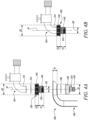
- the adaptor 130 receives an outlet portion 144 (as shown in FIGS. 4A and 4B ) of the tap 104.
- the coupling between the adaptor 130 and the tap connector 134 is a thread coupling, or any other coupling such as a press-fit, a snap-fit and like coupling as used or known in the art.
- the adaptor 130 includes a first portion 146 defining a diameter "D2 and a thickness "T3".
- the first portion 146 may define a blind hole to receive the screw lock 120 (see FIG. 3 ).
- the first portion 146 may also define a number of internal threads (not shown).
- the adaptor 130 also includes a second portion 148 defining a diameter "D3" and a thickness "T4". Further, the diameter "D2" of the first portion 146 is greater than the diameter "D3" of the second portion 148.
- the second portion 148 defines a number of external threads 152.
- the tap connector 134 receives the second portion 148 of the adaptor 130.
- the adaptor 130 further includes a sealing element 154 disposed between the first portion 146 thereof and the outlet portion 144 of the tap 104 for a leak-proof coupling between the adaptor 130 and the tap 104.
- the sealing element 154 may include one or more washers, seals and the like and provides water as well as connection tightness at a connection between the adapter 130 and the tap 104.
- the storage hook 106 may be secured to the adaptor 130 using the screw lock 120. Further, the storage hook 106 is associated with (say coupled around) the adaptor 130. in the illustrated embodiment, the storage hook 106 is removably coupled around the adaptor 130 and the tap connector 134. More particularly, the storage hook 106 is coupled around the adaptor 130 proximate the first end 108 of the storage hook 106. The adaptor 130 is received by the hole 132 of the storage hook 106 since the diameter "D2" of the first portion 146 of the adaptor 130 is approximately equal to the hole diameter "D1" of the hole 132.
- the hole 132 may partially receive the adaptor 130 since the thickness "T3" of the first portion 146 of the adaptor 130 is greater than the thickness " T1 " of the first end 108 of the storage hook 106. Further, the counterbore or countersink profile of the hole 132 may receive the second portion 148 of the adaptor 130. A combined thickness "T2", “T3” of the adapter 130 is greater than the first thickness " T1 " of the first end 108 of the storage hook 106.
- a portion of the adapter 130 at the first portion 146 extends out partially in an upward direction from the storage hook 106 to couple with the outlet portion 144 of the tap 104 and a portion of the adapter 130 at the second portion 148 extends out partially in a downward direction from the storage hook 106 to receive the tap connector 134 (see FIG. 5 ). Furthermore, the thickness "T4" of the second portion 148 of the adaptor 130 is greater than the thickness " T1 " of the first end 108 of the storage hook 106.
- the storage hook 106 may be coupled around the adaptor 130. This may allow implementation benefits along with ease of assembly or disassembly of the storage hook 106 with the adaptor 130.
- the storage hook 106 may be fixed with the adaptor 130. The fixing of the storage hook 106 with the adaptor 130 may allow selective locking or rotation of the storage hook 106 with respect to the adaptor 130.
- the present disclosure allows any association, arrangement, coupling, fixing, and the like between the storage hook 106 and the adaptor 130, within the scope of the present invention as claimed.
- FIGS. 4A, 4B , 4C, and 4D show the assembly of the hose storage unit 100 with the tap 104 (see FIG. 5 ).
- the adaptor 130, the storage hook 106, the tap connector 134, and the tap 104 are shown in an unassembled configuration.
- the adaptor 130 is threadably coupled to the outlet portion 144 of the tap 104.
- the outlet portion 144 of the tap 104 may define external threads (not shown) for threadable coupling of the adaptor 130.
- FIG. 4C in a third position, the storage hook 106 is coupled around the adaptor 130.
- the tap connector 134 is threadably coupled to the second portion 148 of the adaptor 130 to fluidly connect the tap connector 134 (and thereby the hose 102, see FIG. 5 ) and the tap 104.
- the hose connector 142 is coupled to the second coupling portion 140 of the tap connector 134.
- the hose connector 142 may include a body portion (not shown) having an arrangement such as threads that allow engagement of the hose 102 with the hose connector 142.
- the present invention provides an improved and simplified design of the hose storage unit 100 which allows easy installation.
- the new design of the hose storage unit 100 can be accommodated in compact spaces.
- the hose storage unit 100 does not require an external structure such as a wall for mounting the hose storage unit 100 or components thereof and can be directly stored proximate the tap 104.
- the hose storage unit 100 includes fewer parts thus making the assembly simple in design and cost effective.
- the storage hook 106 is directly connected to the adaptor 130 as a screw element. Therefore, a liquid can be fed directly into the hose 102 through the adaptor 130.
- the storage hook 106 can be rotated relative to the tap 104 around the central axis " A1 " of the adaptor 130, thereby allowing storage of the hose 102 at various positions relative to the tap 104.
- the hose storage unit 100 user friendly and improves ergonomics.
- the hose 102 can be quickly assembled and disassembled from the tap 104 using the hose storage unit 100 described herein.
- the adaptor 130 includes the sealing element 154 that provides tightness between the hose storage unit 100 and the tap 104.
- the hose 102 is stored on the storage hook 106 which is coupled to the adaptor 130 hence the weight of the hose 102 is supported by the adaptor 130 thereby preventing damage and breakdown at the hose connection.
Landscapes
- Supports For Pipes And Cables (AREA)
- Quick-Acting Or Multi-Walled Pipe Joints (AREA)
- Domestic Plumbing Installations (AREA)
Claims (8)
- Schlauchaufbewahrungseinheit (100) zum Aufbewahren eines Schlauchs (102) an einem Hahn (104), umfassend:einen Aufbewahrungshaken (106), der angepasst ist, um den Schlauch (102) aufzunehmen;einen Hahnverbinder (134), der angepasst ist, um den Schlauch (102) und den Hahn (104) fluidisch zu verbinden; undeinen Adapter (130), der mit dem Hahn (104) abnehmbar gekoppelt ist und mit dem Hahnverbinder (134) in Eingriff steht,wobei der Adapter (130) den Hahn (104) mit dem Hahnverbinder (134) fluidisch koppelt undwobei der Aufbewahrungshaken (106) mit dem Adapter (130) verknüpft ist;wobei sich ein Abschnitt des Adapters (130) an einem ersten Abschnitt (146) in einer Aufwärtsrichtung von dem Aufbewahrungshaken (106) teilweise heraus erstreckt, um mit einem Auslassabschnitt (144) des Hahns (104) zu koppeln, und sich ein Abschnitt des Adapters (130) an einem zweiten Abschnitt (148) in einer Abwärtsrichtung von dem Aufbewahrungshaken (106) teilweise heraus erstreckt, um den Hahnverbinder (134) aufzunehmen; undwobei der Aufbewahrungshaken (106) ein erstes Ende (108) und ein zweites Ende (110) und einen Schlauchaufnahmeabschnitt (122) nahe des zweiten Endes (110) einschließt; wobei der Schlauchaufnahmeabschnitt (122) des Aufbewahrungshakens (106) hinsichtlich einer Mittelachse ("A1") des Adapters (130) geneigt ist;wobei der Aufbewahrungshaken (106) ferner ein Loch (132) einschließt, um den Adapter (130) aufzunehmen, wobei das Loch (132) nahe des ersten Endes (108) des Aufbewahrungshakens (106) angeordnet ist,dadurch gekennzeichnet, dass:sich ein vertikaler Abschnitt (112) zwischen dem ersten und dem zweiten Ende (108, 110) erstreckt,wobei der Aufbewahrungshaken (106) ein Durchgangsloch (118) nahe des ersten Endes (108) umfasst, wobei das Durchgangsloch (118) konfiguriert ist, um eine Schraubensicherung (120), die ein selektives Sichern des Aufbewahrungshakens (106) ermöglicht, aufzunehmen,wobei der Aufbewahrungshaken (106) ferner eine erste Oberfläche (114) und eine zweite Oberfläche (116) umfasst, wobei die erste Oberfläche (114) und die zweite Oberfläche (116) ein im Allgemeinen kurvenförmiges Profil einschließen.
- Schlauchaufbewahrungseinheit (100) nach Anspruch 1,
wobei der Aufbewahrungshaken (106) mit dem Adapter (130) durch Koppeln des Aufbewahrungshakens (106) um den Adapter (130) herum verknüpft ist. - Schlauchaufbewahrungseinheit (100) nach Anspruch 2,
wobei der Aufbewahrungshaken (106) um den Adapter (130) und den Hahnverbinder (134) herum abnehmbar gekoppelt ist. - Schlauchaufbewahrungseinheit (100) nach Anspruch 1,
wobei der Aufbewahrungshaken (106) mit dem Adapter (130) durch Befestigen des Aufbewahrungshakens (106) mit dem Adapter (130) verknüpft ist. - Schlauchaufbewahrungseinheit (100) nach einem der vorstehenden Ansprüche,
wobei die Kupplung zwischen dem Adapter (130) und dem Hahnverbinder (134) eine Gewindekupplung ist. - Schlauchaufbewahrungseinheit (100) nach einem der vorstehenden Ansprüche,
wobei der Adapter (130) mit dem Hahn (104) gewindegekoppelt ist. - Schlauchaufbewahrungseinheit (100) nach einem der vorstehenden Ansprüche,
wobei der Schlauchaufnahmeabschnitt (122) des Aufbewahrungshakens (106) im Wesentlichen horizontal ist. - Schlauchaufbewahrungseinheit (100) nach einem der vorstehenden Ansprüche,
wobei der Aufbewahrungshaken (106) eine "U"-Form aufweist.
Applications Claiming Priority (2)
| Application Number | Priority Date | Filing Date | Title |
|---|---|---|---|
| EP21158863.7A EP4049957A1 (de) | 2021-02-24 | 2021-02-24 | Schlauchlagereinheit zur lagerung eines schlauchs |
| PCT/EP2021/083640 WO2022179730A1 (en) | 2021-02-24 | 2021-11-30 | Hose storage unit for storing hose |
Publications (2)
| Publication Number | Publication Date |
|---|---|
| EP4240682A1 EP4240682A1 (de) | 2023-09-13 |
| EP4240682B1 true EP4240682B1 (de) | 2024-06-05 |
Family
ID=74732700
Family Applications (2)
| Application Number | Title | Priority Date | Filing Date |
|---|---|---|---|
| EP21158863.7A Withdrawn EP4049957A1 (de) | 2021-02-24 | 2021-02-24 | Schlauchlagereinheit zur lagerung eines schlauchs |
| EP21824320.2A Active EP4240682B1 (de) | 2021-02-24 | 2021-11-30 | Schlauchlagereinheit zur lagerung eines schlauchs |
Family Applications Before (1)
| Application Number | Title | Priority Date | Filing Date |
|---|---|---|---|
| EP21158863.7A Withdrawn EP4049957A1 (de) | 2021-02-24 | 2021-02-24 | Schlauchlagereinheit zur lagerung eines schlauchs |
Country Status (3)
| Country | Link |
|---|---|
| EP (2) | EP4049957A1 (de) |
| CN (1) | CN116897133B (de) |
| WO (1) | WO2022179730A1 (de) |
Families Citing this family (1)
| Publication number | Priority date | Publication date | Assignee | Title |
|---|---|---|---|---|
| DE102024122475A1 (de) * | 2024-08-07 | 2026-02-12 | Timm Greschner | Schlauchhalter |
Family Cites Families (11)
| Publication number | Priority date | Publication date | Assignee | Title |
|---|---|---|---|---|
| US2111811A (en) * | 1937-03-05 | 1938-03-22 | John N Schichtel | Fire hose rack |
| US2569857A (en) * | 1946-03-06 | 1951-10-02 | Klingerit Inc | Combined mixing unit and hose rack |
| US5005790A (en) * | 1988-10-31 | 1991-04-09 | Harris Iii John H | Hose holding fixture |
| JP3141067B2 (ja) * | 1999-04-16 | 2001-03-05 | 株式会社フジアウテック | 散水用ホースの収納掛け具 |
| US20090272857A1 (en) * | 2008-05-01 | 2009-11-05 | Presidential Partners,L.L.C. | Faucet-supported hose retaining apparatus |
| KR20110024876A (ko) * | 2009-09-03 | 2011-03-09 | 이정신 | 소방호스 걸이 |
| EP2709938B1 (de) * | 2011-05-16 | 2015-07-01 | Alfred Kärcher GmbH & Co. KG | Schlauchaufbewahrungseinrichtung |
| RU2015145506A (ru) * | 2013-03-26 | 2017-05-18 | Хускварна Аб | Упаковочная тара для бухты шланга |
| CN108290702B (zh) * | 2015-10-01 | 2019-11-05 | As 美国股份有限公司 | 拉出式龙头软管缩回系统和方法 |
| WO2017148522A1 (en) | 2016-03-03 | 2017-09-08 | Husqvarna Ab | Hose holder |
| US9748755B1 (en) * | 2016-09-21 | 2017-08-29 | Siemens Industry, Inc. | Clip-based non-metallic fittings for attachment of flexible metallic conduit |
-
2021
- 2021-02-24 EP EP21158863.7A patent/EP4049957A1/de not_active Withdrawn
- 2021-11-30 CN CN202180094521.6A patent/CN116897133B/zh active Active
- 2021-11-30 EP EP21824320.2A patent/EP4240682B1/de active Active
- 2021-11-30 WO PCT/EP2021/083640 patent/WO2022179730A1/en not_active Ceased
Also Published As
| Publication number | Publication date |
|---|---|
| WO2022179730A1 (en) | 2022-09-01 |
| EP4049957A1 (de) | 2022-08-31 |
| CN116897133A (zh) | 2023-10-17 |
| EP4240682A1 (de) | 2023-09-13 |
| CN116897133B (zh) | 2026-04-10 |
Similar Documents
| Publication | Publication Date | Title |
|---|---|---|
| US5246254A (en) | Anti-kinking device for garden hoses | |
| WO2022179730A1 (en) | Hose storage unit for storing hose | |
| CN106439149A (zh) | 一种设置支撑出水组件的水龙头 | |
| KR101660643B1 (ko) | 벽면 부착형 샤워기 | |
| US20200129016A1 (en) | Toilet paper roll holder attachment system | |
| US4575005A (en) | Hose arrangement for a car wash | |
| JP4851490B2 (ja) | 配設体の支持具 | |
| JP3394168B2 (ja) | 吊り金具 | |
| EP3423388B1 (de) | Schlauchhalter | |
| JP6456167B2 (ja) | 吐水装置 | |
| EP4241001B1 (de) | Vorrichtung zum tragen eines objekts | |
| KR100666554B1 (ko) | 소화전함용 소방호스걸이 | |
| US5628341A (en) | Mounting assembly for flexible tubing | |
| CN209733913U (zh) | 用于洗碗机的加水组件及具有其的洗碗机 | |
| CN210890272U (zh) | 水龙头 | |
| CN212567851U (zh) | 一种可调节连接装置 | |
| CN220868376U (zh) | 一种固定架以及壁挂式马桶 | |
| CN107542233B (zh) | 弯管转角连接结构 | |
| US20250334216A1 (en) | Rotatable Water Pipe Joint and Assembly Method Thereof | |
| WO2002061323A1 (en) | Hose coupling | |
| CN219374462U (zh) | 一种手柄及烹饪容器 | |
| KR200160959Y1 (ko) | 토수위치 조절이 가능한 토수구조 | |
| US20250194863A1 (en) | Liquid distributor | |
| CN219866626U (zh) | 一种油管固定机构 | |
| CN213745266U (zh) | 一种观测廊道线管固定架 |
Legal Events
| Date | Code | Title | Description |
|---|---|---|---|
| STAA | Information on the status of an ep patent application or granted ep patent |
Free format text: STATUS: UNKNOWN |
|
| STAA | Information on the status of an ep patent application or granted ep patent |
Free format text: STATUS: THE INTERNATIONAL PUBLICATION HAS BEEN MADE |
|
| PUAI | Public reference made under article 153(3) epc to a published international application that has entered the european phase |
Free format text: ORIGINAL CODE: 0009012 |
|
| STAA | Information on the status of an ep patent application or granted ep patent |
Free format text: STATUS: REQUEST FOR EXAMINATION WAS MADE |
|
| 17P | Request for examination filed |
Effective date: 20230605 |
|
| AK | Designated contracting states |
Kind code of ref document: A1 Designated state(s): AL AT BE BG CH CY CZ DE DK EE ES FI FR GB GR HR HU IE IS IT LI LT LU LV MC MK MT NL NO PL PT RO RS SE SI SK SM TR |
|
| GRAP | Despatch of communication of intention to grant a patent |
Free format text: ORIGINAL CODE: EPIDOSNIGR1 |
|
| STAA | Information on the status of an ep patent application or granted ep patent |
Free format text: STATUS: GRANT OF PATENT IS INTENDED |
|
| DAV | Request for validation of the european patent (deleted) | ||
| DAX | Request for extension of the european patent (deleted) | ||
| INTG | Intention to grant announced |
Effective date: 20240326 |
|
| GRAS | Grant fee paid |
Free format text: ORIGINAL CODE: EPIDOSNIGR3 |
|
| GRAA | (expected) grant |
Free format text: ORIGINAL CODE: 0009210 |
|
| STAA | Information on the status of an ep patent application or granted ep patent |
Free format text: STATUS: THE PATENT HAS BEEN GRANTED |
|
| P01 | Opt-out of the competence of the unified patent court (upc) registered |
Effective date: 20240404 |
|
| AK | Designated contracting states |
Kind code of ref document: B1 Designated state(s): AL AT BE BG CH CY CZ DE DK EE ES FI FR GB GR HR HU IE IS IT LI LT LU LV MC MK MT NL NO PL PT RO RS SE SI SK SM TR |
|
| REG | Reference to a national code |
Ref country code: CH Ref legal event code: EP |
|
| REG | Reference to a national code |
Ref country code: DE Ref legal event code: R096 Ref document number: 602021014177 Country of ref document: DE |
|
| REG | Reference to a national code |
Ref country code: IE Ref legal event code: FG4D |
|
| REG | Reference to a national code |
Ref country code: LT Ref legal event code: MG9D |
|
| PG25 | Lapsed in a contracting state [announced via postgrant information from national office to epo] |
Ref country code: BG Free format text: LAPSE BECAUSE OF FAILURE TO SUBMIT A TRANSLATION OF THE DESCRIPTION OR TO PAY THE FEE WITHIN THE PRESCRIBED TIME-LIMIT Effective date: 20240605 |
|
| REG | Reference to a national code |
Ref country code: NL Ref legal event code: MP Effective date: 20240605 |
|
| PG25 | Lapsed in a contracting state [announced via postgrant information from national office to epo] |
Ref country code: HR Free format text: LAPSE BECAUSE OF FAILURE TO SUBMIT A TRANSLATION OF THE DESCRIPTION OR TO PAY THE FEE WITHIN THE PRESCRIBED TIME-LIMIT Effective date: 20240605 Ref country code: FI Free format text: LAPSE BECAUSE OF FAILURE TO SUBMIT A TRANSLATION OF THE DESCRIPTION OR TO PAY THE FEE WITHIN THE PRESCRIBED TIME-LIMIT Effective date: 20240605 |
|
| PG25 | Lapsed in a contracting state [announced via postgrant information from national office to epo] |
Ref country code: GR Free format text: LAPSE BECAUSE OF FAILURE TO SUBMIT A TRANSLATION OF THE DESCRIPTION OR TO PAY THE FEE WITHIN THE PRESCRIBED TIME-LIMIT Effective date: 20240906 |
|
| PG25 | Lapsed in a contracting state [announced via postgrant information from national office to epo] |
Ref country code: ES Free format text: LAPSE BECAUSE OF FAILURE TO SUBMIT A TRANSLATION OF THE DESCRIPTION OR TO PAY THE FEE WITHIN THE PRESCRIBED TIME-LIMIT Effective date: 20240605 |
|
| PG25 | Lapsed in a contracting state [announced via postgrant information from national office to epo] |
Ref country code: LV Free format text: LAPSE BECAUSE OF FAILURE TO SUBMIT A TRANSLATION OF THE DESCRIPTION OR TO PAY THE FEE WITHIN THE PRESCRIBED TIME-LIMIT Effective date: 20240605 |
|
| PG25 | Lapsed in a contracting state [announced via postgrant information from national office to epo] |
Ref country code: NO Free format text: LAPSE BECAUSE OF FAILURE TO SUBMIT A TRANSLATION OF THE DESCRIPTION OR TO PAY THE FEE WITHIN THE PRESCRIBED TIME-LIMIT Effective date: 20240905 Ref country code: LV Free format text: LAPSE BECAUSE OF FAILURE TO SUBMIT A TRANSLATION OF THE DESCRIPTION OR TO PAY THE FEE WITHIN THE PRESCRIBED TIME-LIMIT Effective date: 20240605 Ref country code: HR Free format text: LAPSE BECAUSE OF FAILURE TO SUBMIT A TRANSLATION OF THE DESCRIPTION OR TO PAY THE FEE WITHIN THE PRESCRIBED TIME-LIMIT Effective date: 20240605 Ref country code: GR Free format text: LAPSE BECAUSE OF FAILURE TO SUBMIT A TRANSLATION OF THE DESCRIPTION OR TO PAY THE FEE WITHIN THE PRESCRIBED TIME-LIMIT Effective date: 20240906 Ref country code: FI Free format text: LAPSE BECAUSE OF FAILURE TO SUBMIT A TRANSLATION OF THE DESCRIPTION OR TO PAY THE FEE WITHIN THE PRESCRIBED TIME-LIMIT Effective date: 20240605 Ref country code: ES Free format text: LAPSE BECAUSE OF FAILURE TO SUBMIT A TRANSLATION OF THE DESCRIPTION OR TO PAY THE FEE WITHIN THE PRESCRIBED TIME-LIMIT Effective date: 20240605 Ref country code: BG Free format text: LAPSE BECAUSE OF FAILURE TO SUBMIT A TRANSLATION OF THE DESCRIPTION OR TO PAY THE FEE WITHIN THE PRESCRIBED TIME-LIMIT Effective date: 20240605 Ref country code: RS Free format text: LAPSE BECAUSE OF FAILURE TO SUBMIT A TRANSLATION OF THE DESCRIPTION OR TO PAY THE FEE WITHIN THE PRESCRIBED TIME-LIMIT Effective date: 20240905 |
|
| PG25 | Lapsed in a contracting state [announced via postgrant information from national office to epo] |
Ref country code: NL Free format text: LAPSE BECAUSE OF FAILURE TO SUBMIT A TRANSLATION OF THE DESCRIPTION OR TO PAY THE FEE WITHIN THE PRESCRIBED TIME-LIMIT Effective date: 20240605 |
|
| REG | Reference to a national code |
Ref country code: AT Ref legal event code: MK05 Ref document number: 1692335 Country of ref document: AT Kind code of ref document: T Effective date: 20240605 |
|
| PG25 | Lapsed in a contracting state [announced via postgrant information from national office to epo] |
Ref country code: NL Free format text: LAPSE BECAUSE OF FAILURE TO SUBMIT A TRANSLATION OF THE DESCRIPTION OR TO PAY THE FEE WITHIN THE PRESCRIBED TIME-LIMIT Effective date: 20240605 |
|
| PG25 | Lapsed in a contracting state [announced via postgrant information from national office to epo] |
Ref country code: PT Free format text: LAPSE BECAUSE OF FAILURE TO SUBMIT A TRANSLATION OF THE DESCRIPTION OR TO PAY THE FEE WITHIN THE PRESCRIBED TIME-LIMIT Effective date: 20241007 |
|
| PG25 | Lapsed in a contracting state [announced via postgrant information from national office to epo] |
Ref country code: PT Free format text: LAPSE BECAUSE OF FAILURE TO SUBMIT A TRANSLATION OF THE DESCRIPTION OR TO PAY THE FEE WITHIN THE PRESCRIBED TIME-LIMIT Effective date: 20241007 |
|
| PG25 | Lapsed in a contracting state [announced via postgrant information from national office to epo] |
Ref country code: PL Free format text: LAPSE BECAUSE OF FAILURE TO SUBMIT A TRANSLATION OF THE DESCRIPTION OR TO PAY THE FEE WITHIN THE PRESCRIBED TIME-LIMIT Effective date: 20240605 |
|
| PG25 | Lapsed in a contracting state [announced via postgrant information from national office to epo] |
Ref country code: EE Free format text: LAPSE BECAUSE OF FAILURE TO SUBMIT A TRANSLATION OF THE DESCRIPTION OR TO PAY THE FEE WITHIN THE PRESCRIBED TIME-LIMIT Effective date: 20240605 |
|
| PG25 | Lapsed in a contracting state [announced via postgrant information from national office to epo] |
Ref country code: AT Free format text: LAPSE BECAUSE OF FAILURE TO SUBMIT A TRANSLATION OF THE DESCRIPTION OR TO PAY THE FEE WITHIN THE PRESCRIBED TIME-LIMIT Effective date: 20240605 Ref country code: IS Free format text: LAPSE BECAUSE OF FAILURE TO SUBMIT A TRANSLATION OF THE DESCRIPTION OR TO PAY THE FEE WITHIN THE PRESCRIBED TIME-LIMIT Effective date: 20241005 |
|
| PG25 | Lapsed in a contracting state [announced via postgrant information from national office to epo] |
Ref country code: CZ Free format text: LAPSE BECAUSE OF FAILURE TO SUBMIT A TRANSLATION OF THE DESCRIPTION OR TO PAY THE FEE WITHIN THE PRESCRIBED TIME-LIMIT Effective date: 20240605 |
|
| PG25 | Lapsed in a contracting state [announced via postgrant information from national office to epo] |
Ref country code: RO Free format text: LAPSE BECAUSE OF FAILURE TO SUBMIT A TRANSLATION OF THE DESCRIPTION OR TO PAY THE FEE WITHIN THE PRESCRIBED TIME-LIMIT Effective date: 20240605 Ref country code: SK Free format text: LAPSE BECAUSE OF FAILURE TO SUBMIT A TRANSLATION OF THE DESCRIPTION OR TO PAY THE FEE WITHIN THE PRESCRIBED TIME-LIMIT Effective date: 20240605 |
|
| PG25 | Lapsed in a contracting state [announced via postgrant information from national office to epo] |
Ref country code: SM Free format text: LAPSE BECAUSE OF FAILURE TO SUBMIT A TRANSLATION OF THE DESCRIPTION OR TO PAY THE FEE WITHIN THE PRESCRIBED TIME-LIMIT Effective date: 20240605 |
|
| PG25 | Lapsed in a contracting state [announced via postgrant information from national office to epo] |
Ref country code: SM Free format text: LAPSE BECAUSE OF FAILURE TO SUBMIT A TRANSLATION OF THE DESCRIPTION OR TO PAY THE FEE WITHIN THE PRESCRIBED TIME-LIMIT Effective date: 20240605 Ref country code: SK Free format text: LAPSE BECAUSE OF FAILURE TO SUBMIT A TRANSLATION OF THE DESCRIPTION OR TO PAY THE FEE WITHIN THE PRESCRIBED TIME-LIMIT Effective date: 20240605 Ref country code: RO Free format text: LAPSE BECAUSE OF FAILURE TO SUBMIT A TRANSLATION OF THE DESCRIPTION OR TO PAY THE FEE WITHIN THE PRESCRIBED TIME-LIMIT Effective date: 20240605 Ref country code: PL Free format text: LAPSE BECAUSE OF FAILURE TO SUBMIT A TRANSLATION OF THE DESCRIPTION OR TO PAY THE FEE WITHIN THE PRESCRIBED TIME-LIMIT Effective date: 20240605 Ref country code: IS Free format text: LAPSE BECAUSE OF FAILURE TO SUBMIT A TRANSLATION OF THE DESCRIPTION OR TO PAY THE FEE WITHIN THE PRESCRIBED TIME-LIMIT Effective date: 20241005 Ref country code: EE Free format text: LAPSE BECAUSE OF FAILURE TO SUBMIT A TRANSLATION OF THE DESCRIPTION OR TO PAY THE FEE WITHIN THE PRESCRIBED TIME-LIMIT Effective date: 20240605 Ref country code: CZ Free format text: LAPSE BECAUSE OF FAILURE TO SUBMIT A TRANSLATION OF THE DESCRIPTION OR TO PAY THE FEE WITHIN THE PRESCRIBED TIME-LIMIT Effective date: 20240605 Ref country code: AT Free format text: LAPSE BECAUSE OF FAILURE TO SUBMIT A TRANSLATION OF THE DESCRIPTION OR TO PAY THE FEE WITHIN THE PRESCRIBED TIME-LIMIT Effective date: 20240605 |
|
| PG25 | Lapsed in a contracting state [announced via postgrant information from national office to epo] |
Ref country code: IT Free format text: LAPSE BECAUSE OF FAILURE TO SUBMIT A TRANSLATION OF THE DESCRIPTION OR TO PAY THE FEE WITHIN THE PRESCRIBED TIME-LIMIT Effective date: 20240605 |
|
| REG | Reference to a national code |
Ref country code: DE Ref legal event code: R097 Ref document number: 602021014177 Country of ref document: DE |
|
| PLBE | No opposition filed within time limit |
Free format text: ORIGINAL CODE: 0009261 |
|
| STAA | Information on the status of an ep patent application or granted ep patent |
Free format text: STATUS: NO OPPOSITION FILED WITHIN TIME LIMIT |
|
| PG25 | Lapsed in a contracting state [announced via postgrant information from national office to epo] |
Ref country code: DK Free format text: LAPSE BECAUSE OF FAILURE TO SUBMIT A TRANSLATION OF THE DESCRIPTION OR TO PAY THE FEE WITHIN THE PRESCRIBED TIME-LIMIT Effective date: 20240605 |
|
| 26N | No opposition filed |
Effective date: 20250306 |
|
| REG | Reference to a national code |
Ref country code: CH Ref legal event code: PL |
|
| PG25 | Lapsed in a contracting state [announced via postgrant information from national office to epo] |
Ref country code: MC Free format text: LAPSE BECAUSE OF FAILURE TO SUBMIT A TRANSLATION OF THE DESCRIPTION OR TO PAY THE FEE WITHIN THE PRESCRIBED TIME-LIMIT Effective date: 20240605 |
|
| PG25 | Lapsed in a contracting state [announced via postgrant information from national office to epo] |
Ref country code: LU Free format text: LAPSE BECAUSE OF NON-PAYMENT OF DUE FEES Effective date: 20241130 |
|
| REG | Reference to a national code |
Ref country code: CH Ref legal event code: PL |
|
| PG25 | Lapsed in a contracting state [announced via postgrant information from national office to epo] |
Ref country code: CH Free format text: LAPSE BECAUSE OF NON-PAYMENT OF DUE FEES Effective date: 20241130 |
|
| REG | Reference to a national code |
Ref country code: BE Ref legal event code: MM Effective date: 20241130 |
|
| PG25 | Lapsed in a contracting state [announced via postgrant information from national office to epo] |
Ref country code: SE Free format text: LAPSE BECAUSE OF FAILURE TO SUBMIT A TRANSLATION OF THE DESCRIPTION OR TO PAY THE FEE WITHIN THE PRESCRIBED TIME-LIMIT Effective date: 20240605 |
|
| PG25 | Lapsed in a contracting state [announced via postgrant information from national office to epo] |
Ref country code: BE Free format text: LAPSE BECAUSE OF NON-PAYMENT OF DUE FEES Effective date: 20241130 |
|
| PG25 | Lapsed in a contracting state [announced via postgrant information from national office to epo] |
Ref country code: FR Free format text: LAPSE BECAUSE OF NON-PAYMENT OF DUE FEES Effective date: 20241130 |
|
| PG25 | Lapsed in a contracting state [announced via postgrant information from national office to epo] |
Ref country code: IE Free format text: LAPSE BECAUSE OF NON-PAYMENT OF DUE FEES Effective date: 20241130 |
|
| PGFP | Annual fee paid to national office [announced via postgrant information from national office to epo] |
Ref country code: DE Payment date: 20251021 Year of fee payment: 5 |
|
| PG25 | Lapsed in a contracting state [announced via postgrant information from national office to epo] |
Ref country code: CY Free format text: LAPSE BECAUSE OF FAILURE TO SUBMIT A TRANSLATION OF THE DESCRIPTION OR TO PAY THE FEE WITHIN THE PRESCRIBED TIME-LIMIT; INVALID AB INITIO Effective date: 20211130 |