EP4240102B1 - Verbindungsaufbau zwischen einer funkausrüstungssteuerung (rec) und einer funkausrüstung (re) in einem fronthaul-netzwerk - Google Patents
Verbindungsaufbau zwischen einer funkausrüstungssteuerung (rec) und einer funkausrüstung (re) in einem fronthaul-netzwerk Download PDFInfo
- Publication number
- EP4240102B1 EP4240102B1 EP23181923.6A EP23181923A EP4240102B1 EP 4240102 B1 EP4240102 B1 EP 4240102B1 EP 23181923 A EP23181923 A EP 23181923A EP 4240102 B1 EP4240102 B1 EP 4240102B1
- Authority
- EP
- European Patent Office
- Prior art keywords
- cpri
- link
- proxy
- radio equipment
- roe
- Prior art date
- Legal status (The legal status is an assumption and is not a legal conclusion. Google has not performed a legal analysis and makes no representation as to the accuracy of the status listed.)
- Active
Links
Images




Classifications
-
- H—ELECTRICITY
- H04—ELECTRIC COMMUNICATION TECHNIQUE
- H04J—MULTIPLEX COMMUNICATION
- H04J3/00—Time-division multiplex systems
- H04J3/02—Details
- H04J3/06—Synchronising arrangements
- H04J3/0602—Systems characterised by the synchronising information used
- H04J3/0605—Special codes used as synchronising signal
- H04J3/0608—Detectors therefor, e.g. correlators, state machines
-
- H—ELECTRICITY
- H04—ELECTRIC COMMUNICATION TECHNIQUE
- H04J—MULTIPLEX COMMUNICATION
- H04J3/00—Time-division multiplex systems
- H04J3/02—Details
- H04J3/06—Synchronising arrangements
- H04J3/0635—Clock or time synchronisation in a network
-
- H—ELECTRICITY
- H04—ELECTRIC COMMUNICATION TECHNIQUE
- H04L—TRANSMISSION OF DIGITAL INFORMATION, e.g. TELEGRAPHIC COMMUNICATION
- H04L1/00—Arrangements for detecting or preventing errors in the information received
- H04L1/0001—Systems modifying transmission characteristics according to link quality, e.g. power backoff
- H04L1/0002—Systems modifying transmission characteristics according to link quality, e.g. power backoff by adapting the transmission rate
-
- H—ELECTRICITY
- H04—ELECTRIC COMMUNICATION TECHNIQUE
- H04W—WIRELESS COMMUNICATION NETWORKS
- H04W28/00—Network traffic management; Network resource management
- H04W28/16—Central resource management; Negotiation of resources or communication parameters, e.g. negotiating bandwidth or QoS [Quality of Service]
- H04W28/18—Negotiating wireless communication parameters
- H04W28/22—Negotiating communication rate
-
- H—ELECTRICITY
- H04—ELECTRIC COMMUNICATION TECHNIQUE
- H04W—WIRELESS COMMUNICATION NETWORKS
- H04W56/00—Synchronisation arrangements
- H04W56/0005—Synchronisation arrangements synchronizing of arrival of multiple uplinks
-
- H—ELECTRICITY
- H04—ELECTRIC COMMUNICATION TECHNIQUE
- H04W—WIRELESS COMMUNICATION NETWORKS
- H04W56/00—Synchronisation arrangements
- H04W56/001—Synchronization between nodes
-
- H—ELECTRICITY
- H04—ELECTRIC COMMUNICATION TECHNIQUE
- H04W—WIRELESS COMMUNICATION NETWORKS
- H04W76/00—Connection management
- H04W76/10—Connection setup
-
- H—ELECTRICITY
- H04—ELECTRIC COMMUNICATION TECHNIQUE
- H04W—WIRELESS COMMUNICATION NETWORKS
- H04W92/00—Interfaces specially adapted for wireless communication networks
- H04W92/04—Interfaces between hierarchically different network devices
- H04W92/10—Interfaces between hierarchically different network devices between terminal device and access point, i.e. wireless air interface
-
- H—ELECTRICITY
- H04—ELECTRIC COMMUNICATION TECHNIQUE
- H04W—WIRELESS COMMUNICATION NETWORKS
- H04W92/00—Interfaces specially adapted for wireless communication networks
- H04W92/04—Interfaces between hierarchically different network devices
- H04W92/12—Interfaces between hierarchically different network devices between access points and access point controllers
-
- H—ELECTRICITY
- H04—ELECTRIC COMMUNICATION TECHNIQUE
- H04J—MULTIPLEX COMMUNICATION
- H04J3/00—Time-division multiplex systems
- H04J3/02—Details
- H04J3/06—Synchronising arrangements
- H04J3/0635—Clock or time synchronisation in a network
- H04J3/0638—Clock or time synchronisation among nodes; Internode synchronisation
- H04J3/0647—Synchronisation among TDM nodes
-
- H—ELECTRICITY
- H04—ELECTRIC COMMUNICATION TECHNIQUE
- H04J—MULTIPLEX COMMUNICATION
- H04J3/00—Time-division multiplex systems
- H04J3/02—Details
- H04J3/06—Synchronising arrangements
- H04J3/0635—Clock or time synchronisation in a network
- H04J3/0638—Clock or time synchronisation among nodes; Internode synchronisation
- H04J3/0658—Clock or time synchronisation among packet nodes
-
- H—ELECTRICITY
- H04—ELECTRIC COMMUNICATION TECHNIQUE
- H04L—TRANSMISSION OF DIGITAL INFORMATION, e.g. TELEGRAPHIC COMMUNICATION
- H04L25/00—Baseband systems
- H04L25/02—Details ; arrangements for supplying electrical power along data transmission lines
- H04L25/0262—Arrangements for detecting the data rate of an incoming signal
-
- H—ELECTRICITY
- H04—ELECTRIC COMMUNICATION TECHNIQUE
- H04W—WIRELESS COMMUNICATION NETWORKS
- H04W84/00—Network topologies
- H04W84/18—Self-organising networks, e.g. ad-hoc networks or sensor networks
- H04W84/20—Leader-follower arrangements
Definitions
- the present disclosure relates to communication systems, in particular, to techniques to provide link establishment between a radio equipment controller (REC) and radio equipment (RE) in a fronthaul network.
- REC radio equipment controller
- RE radio equipment
- CPRI Common Public Radio Interface
- a computer-implemented method may include performing, for one or more link bit rates of a plurality of link bit rates configured for a fronthaul network, Common Public Radio Interface (CPRI) Layer 1 link auto-negotiation operations to establish a CPRI link between a radio equipment controller and a radio equipment of the fronthaul network, the CPRI Layer 1 link auto-negotiation operations comprising: achieving, by a proxy slave, a hyper frame number synchronization with the radio equipment controller at a link bit rate for a first CPRI bit stream transmitted by the radio equipment controller; communicating the first CPRI bit stream and the link bit rate from the proxy slave to a proxy master; transmitting, by the proxy master, the first CPRI bit stream to the radio equipment at the link bit rate and the radio equipment attempting to achieve a hyper frame number synchronization with the first CPRI bit stream; upon the radio equipment achieving the hyper frame number synchronization, the radio equipment communicating a second CPRI bit stream to the proxy master at the link bit rate; upon the proxy
- CPRI Common Public
- a method includes performing, Common Public Radio Interface (CPRI) Layer 1 (L1) link auto-negotiation operations to establish a CPRI link between the REC and RE.
- CPRI Common Public Radio Interface
- L1 link auto-negotiation operations to establish a CPRI link between the REC and RE.
- a proxy slave may achieve a hyper frame number (HFN) synchronization with the REC at a link bit rate for a first CPRI bit stream and communicate the first CPRI bit stream and the link bit rate to a proxy master.
- the proxy master may communicate a second CPRI bit stream to the proxy slave to transmit to the REC.
- the L1 link auto-negotiation operations are completed and CPRI link is established between the REC and the RE when the REC achieves a HFN synchronization for the second CPRI bit stream.
- 'messages' Communications in a network environment can be referred to herein as 'messages', 'messaging', 'signaling', 'data', 'content', 'objects', 'requests', 'queries', 'responses', 'replies', etc. which may be inclusive of packets.
- 'packet' may be used in a generic sense to include packets, frames, segments, datagrams, and/or other generic data units that may be used to transmit communications (e.g., data and/or commands) in a network.
- a packet is a formatted unit of data that can contain control or routing information (e.g., source and destination address, etc.) and data, which is also sometimes referred to as a payload or data payload.
- control or routing information, management information, or the like can be included in packet fields, such as within header(s) and/or trailer(s) of packets.
- 'data', 'information', 'parameters,' and the like as used herein can refer to any type of binary, numeric, voice, video, textual or script data or information or any type of source or object code, or any other suitable data or information in any appropriate format that can be communicated from one point to another in electronic devices and/or networks. Additionally, messages, requests, responses, replies, queries, etc. are forms of network traffic and, therefore, may comprise one or more packets.
- IP Internet Protocol
- IPv4 IP version 4
- IPv6 IP version 6
- a data or user plane generally rely upon three basic components: a data or user plane, a control plane, and a management plane.
- the user plane carries data traffic (e.g., user data traffic), while the control plane and the management plane serve the data plane.
- data traffic e.g., user data traffic
- the control plane and the management plane serve the data plane.
- 'plane' can refer to a separation of traffic, operations, etc. for a network and/or network element or node.
- 3GPP mobile network architectures such as 3GPP Long Term Evolution (LTE) architectures, sometimes referred to as 4th Generation (4G)/LTE architectures, as well as 3GPP 5th Generation (5G) architectures can be implemented via a core network and one or more 3GPP access networks in which user equipment (UEs) connect to a core network via over-the-air Radio Frequency (RF) communications with radio units or radio equipment (RE) of the access networks.
- UEs user equipment
- RF Radio Frequency
- RE radio equipment
- Some 3GPP access networks can be implemented in a configuration that includes a radio equipment controller (REC) that interfaces with the core network and also that interfaces with one or more RE.
- REC radio equipment controller
- an REC may also be referred to as a Baseband Unit (BBU) and an RE may be referred to as a Remote Radio Head (RRH).
- BBU Baseband Unit
- RRH Remote Radio Head
- Both the REC and RE are two basic building blocks of a radio base station.
- the REC is concerned with the Network Interface transport, the radio base station control and management as well as the digital baseband processing.
- the RE provides the analogue and radio frequency functions via a radio head such as filtering, modulation, frequency conversion and amplification or, more generally, RE serves as the air interface, to the user equipment.
- CPRI Common Public Radio Interface
- CPRI is a point to point bit synchronous serial data link between the co-located REC and the RE providing an 'always ON constant bit rate' steady data stream.
- 'data link' and 'link' can be used interchangeably.
- FIG. 1 is a simplified diagram 100 illustrating example details associated with CPRI link bit rate negotiation.
- FIG. 1 illustrates the transmit link bit rates 102 for a CPRI bit stream transmitted by the master port (REC) and receive/decode link bit rates 104 at which a slave port (RE) attempts to receive and decode the master port (REC) transmitted CPRI bit stream in relation to times 110(1)-110(3), as represented along a time axis 110.
- REC master port
- RE slave port
- a CPRI link negotiation is performed to negotiate a common matching link bit rate for establishing the bi-directional CPRI data link between co-located REC and RE.
- CPRI Specification version 7.0 (v7.0), published October 9, 2015, describes the current procedure for link negotiation between REC and RE in direct connected deployments, in which the master port (REC) drives the link bring-up with the slave port (RE) and link bit rate auto negotiation, L1 synchronization, and frame synchronization/alignment all happen together directly between the co-located REC and RE.
- bit rate is referred to as 'line bit rate'; however, for purposes of discussions herein, the term 'link bit rate' will be used.
- the terms 'link auto-negotiation', 'link negotiation', and 'link bit-rate negotiation' may be used interchangeably.
- the terms 'synchronization' and 'sync' may be used interchangeably.
- CPRI L1 synchronization accomplishes two things between the master and slave ports: byte alignment and hyper frame alignment for CPRI bit streams transmitted via the data link between the co-located REC and RE at a common matching link bit rate for the master and slave.
- C&M protocol setup and control and management
- L2 negotiations are performed to determine a highest common matching link bit rate for the master and slave (if not already selected during the L1 sync) and also to determine a CPRI (in-band) C&M channel bit rate, C&M protocol, and vendor specific negotiations/signaling.
- the master port (REC) has a capability set in which it is capable of ⁇ 9.8, 4.9, 2.5, and 1.2 ⁇ Gigabits per second (Gbps) CPRI link bit rates and the slave port (RE) is capable of ⁇ 2.5 and 1.2 ⁇ Gbps CPRI link bit rates, the following occurs:
- link negotiation procedure can be performed according CPRI Specification v7.0 when the REC and RE are co-located and directly connected, the procedure cannot work in fronthaul networks in which the REC and RE are interconnected through one or more intermediate nodes via a packet-based network, such as an Ethernet network.
- the presence of the intermediate nodes in a fronthaul network poses a discontinuity problem for establishing the CPRI link negotiation (e.g., comprising link bit rate negotiation, L1 synchronization, and frame synchronization/alignment) between the REC and RE using the process prescribed by CPRI Specification v7.0.
- the REC and RE endpoints cannot communicate directly with each other due to presence of CPRI interfacing Ethernet nodes as all these nodes may be running at different rates. Without having a commonly understandable CPRI link bit rate across the entire CPRI path for the CPRI interfacing nodes, the end-to-end CPRI link negotiation cannot be achieved.
- Ethernet nodes capable of CPRI mapping and de-mapping e.g., mapping and de-mapping between a CPRI bit stream and Ethernet frames and vice-versa, depending on the direction of communications
- the Ethernet node capable of CPRI mapping/de-mapping connected directly to the REC is referred to herein as a 'Proxy Slave' or a 'CPRI Proxy Slave'
- the Ethernet node capable of CPRI mapping/de-mapping connected directly to the RE is referred to herein as a 'Proxy Master' or a 'CPRI Proxy Master'.
- the Proxy Master and the Proxy Slave nodes may be referred to generally as 'proxy nodes'.
- the Proxy Master and Proxy Slave can communicate over a packet-based network, such as an Ethernet network, using Radio over Ethernet (RoE) communications, as prescribed by the Institute of Electrical and Electronics Engineers (IEEE) 1914.1 and IEEE 1914.3 Specifications, approved September 27, 2018. IEEE 1914.1 and 1914.3 (referred to herein as 'IEEE 1914 standards') provide standards for encapsulation and mapping/de-mapping of radio data, such as CPRI bit streams, and/or potentially control and/or management packets within Ethernet frames. For a given Ethernet frame, radio data and/or potentially control and/or management packets can be included within a RoE frame that is encapsulated in the Ethernet frame. As discussed in further detail herein, a RoE frame can include an RoE header and an RoE payload.
- RoE Radio over Ethernet
- the IEEE 1914 standards define different RoE mappers/de-mappers, including: structure-aware, structure-agnostic, and native mode in which structure-aware mapping/de-mapping operations can be used for CPRI data, structure-agnostic mapping/de-mapping operations can be used for any digitized radio data, and native mode mapping/de-mapping operations can be used for digitized radio In-phase/Quadrature (I/Q) payload data.
- structure-aware mapping/de-mapping operations can be used for CPRI data
- structure-agnostic mapping/de-mapping operations can be used for any digitized radio data
- native mode mapping/de-mapping operations can be used for digitized radio In-phase/Quadrature (I/Q) payload data.
- the structure-agnostic RoE mapper is considered for embodiments described herein. While the IEEE 1914.1 and IEEE 1914.3 Specifications provide standards for encapsulation and mapping/de-mapping of CPRI bit streams over packet-based fronthaul transport networks, the standards do not cover how end-to-end link negotiations can be performed between an REC and RE in fronthaul networks.
- One possible solution arriving at a common link rate on all nodes including the REC and RE in the CPRI path flow may be to use a manual static configuration at all CPRI endpoints and the intermediate CPRI interfacing nodes; however, such a solution is error prone, inefficient at times, and not scalable.
- Example embodiments described herein provide techniques to overcome these hurdles by providing a mechanism to provide CPRI link establishment between an REC and an RE in an Ethernet-based fronthaul network.
- a CPRI link for a fronthaul network is a cross product of CPRI and Ethernet as the end-to-end nodes (REC/RE) use CPRI only to communicate with each other via the proxy nodes, which perform mapping/de-mapping and link monitoring operations.
- REC/RE end-to-end nodes
- embodiments described herein may facilitate end-to-end CPRI link synchronization between an REC and an RE in which the REC represents one end and the RE represents another end of the end-to-end CPRI link synchronization.
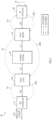
- FIG. 2 is a simplified diagram illustrating example details associated with a fronthaul network 200 in which techniques to provide link establishment between an REC 210 and RE 220 may be implemented, according to an example embodiment.
- FIG. 2 includes REC 210, RE 220, a Proxy Slave 230, a Proxy Master 240, and an Ethernet network 250.
- REC 210 may also be referred to as the 'CPRI Master'
- RE 220 may be referred to as the 'CPRI Slave'.
- fronthaul network 200 may also be referred to as an Ethernet-based fronthaul network 200.
- At least one CPRI interface element/port may be configured for each of Proxy Slave 230 and Proxy Master 240 in which the CPRI port state machine may be configured for the CPRI interface element/port for each of Proxy Slave 230 and Proxy Master 240.
- some operations of Proxy Slave 230 involving L1 link negotiations/sync with REC 210 may differ from the standard negotiation/sync processes as described by CPRI Specification v7.0, while other operations, such as updating internal states of the CPRI port state machine for REC 210 may follow the processes described by CPRI Specification v7.0.
- at least one Ethernet interface element/port may also be configured for each of Proxy Slave 230 and Proxy Master 24 to facilitate communications via Ethernet network 250.
- the interconnection between REC 210 and Proxy Slave 230 is a CPRI interconnection
- the interconnection between Proxy Slave 230 and Ethernet network 250 is an Ethernet interconnection
- the interconnection between RE 220 and Proxy Master 240 is a CPRI interconnection
- the interconnection between Proxy Master 240 and Ethernet network 250 is an Ethernet interconnection.
- REC 210 may further interface with a 3GPP mobile core network (not shown).
- Proxy Slave 230 is an Ethernet node connected directly to REC 210 and also to Ethernet network 250. Proxy Slave 230 is capable of performing CPRI mapping and de-mapping for various communications/operations within fronthaul network 200, as discussed herein.
- Proxy Master 240 is an Ethernet node connected directly to RE 220 and also to Ethernet network 250. Proxy Master 240 is capable of performing CPRI mapping and de-mapping for various communications/operations, as discussed herein. Proxy Slave 230 and Proxy Master 240 may interface with each other using Ethernet-based communications using Ethernet network 250.
- RoE frames encapsulated within Ethernet frames may be utilized for communications of radio data to/from REC 210 and RE 220 in which Proxy Slave 230 and Proxy Master 240 can map/de-map CPRI bit streams to/from RoE frames for communications across Ethernet network 250 and with each of REC 210 and RE 220 (e.g., via the CPRI interconnection between Proxy Slave 230 and REC 210 and also via the CPRI interconnection between Proxy Master 240 and RE 220) to facilitate end-to-end communications between REC 210 and RE 220.
- a RoE header of an RoE frame may be enhanced to include link bit rate information to facilitate end-to-end L1 link auto-negotiation operations and CPRI link establishment between REC 210 and RE 220 for fronthaul network 200.
- FIG. 3 is a simplified diagram illustrating example details associated with operations 300 to provide link establishment between the REC 210 and RE 220 of the fronthaul network 200 of FIG. 2 , according to an example embodiment.
- operations 300 to provide L1 link auto-negotiation and link establishment between the REC 210 and RE 220 may be generally performed as follows:
- pre-requisites for starting operations 300 associated with L1 link auto-negotiation between REC 210 and RE 220 may include, but not be limited to: that Proxy Slave 230 and Proxy Master 240 are configured or otherwise synchronized using a control protocol to have common subset of link bit rates (e.g., they do not necessarily have to have the same set of link bit rates); the same RoE mapperType value is set to be the same at both Proxy Slave 230 and Proxy Master 240 (i.e., both support the same mapperType mode of either the Tunneling mode or the Line coding aware mode, as specified in the IEEE 1914 standards); that packet-based communication between Proxy Slave 230 and Proxy Master 240 via Ethernet network 250 is operational; and that REC 210 and RE 220 of varied link bit rate capabilities are set up and ready for
- operations 300 may begin at 301 at which Proxy Slave 230 will try to establish HFN sync with REC 210.
- Proxy Slave 230 will follow the standard procedure described in CPRI v7.0 Specification for the operations at 301 in which REC 210 will transmit a CPRI bit stream and change its transmit link bit rate every T1 time interval (i.e., 0.9-1.1 seconds) and Proxy Slave 230 will be selecting different line bit rates for reception after every T2 time interval (i.e., 3.9-4.1 seconds).
- Proxy Slave 230 on reaching HFN sync at 301, Proxy Slave 230 will not transmit back towards REC 210 at the link bit rate. Rather, the operations may include, at 302, Proxy Slave 230 packetizing/encapsulating the CPRI bit stream received from REC 210 into RoE frames (e.g., into the RoE payload of RoE frames) and transmitting the RoE frames encapsulated within Ethernet frames (towards the RE 220 direction) to Proxy Master 240 via Ethernet network 250. In the RoE header of the RoE frames, Proxy Slave 230 will indicate the current CPRI link bit rate with which it has achieved the HFN sync with REC 210.
- RoE frames e.g., into the RoE payload of RoE frames
- Ethernet frames towards the RE 220 direction
- 4-bits from the optional reserved bits field in the orderInfo - seqNum field in the RoE header can be used for carrying the CPRI link bit rate information from Proxy Slave 230 to Proxy Master 240 during L1 link auto-negotiation operations. Additional details related to use of the RoE header to communicate link bit rate information are discussed below with reference to FIGs. 4A-4C .
- the operations may further include, at 303, Proxy Master 240, on receiving the RoE frames from Proxy Slave 230, determining the CPRI link bit rate information from the RoE header and begin playing out (e.g., transmitting) the CPRI bit stream towards the RE 220 as per the same CPRI link bit rate determined from the RoE header of the RoE frames.
- Proxy Master 240 can use the received RoE frames and extract out/de-map the radio data from the received RoE frames to transmit the CPRI bit stream to RE 220 at 303.
- Proxy Master 240 will receive the RoE frames after a propagation delay from REC 210 to Proxy Master 240.
- the propagation delay will be very small (less than a millisecond) as compared to the overall time window of T1 time (0.9-1.1 seconds) that occurs before REC 210 will move to a new link bit rate.
- the operations may include, simultaneously at the other end of the CPRI interconnection with Proxy Master 240, the CPRI port of RE 220 is attempting, at 304, to receive and decode the CPRI bit stream directly at the highest available link bit rate for the capability set configured for RE 220.
- RE 220 will be selecting, at 304, different line bit rates after every T2 time interval (3.9-4.1 seconds) and will be repeating the same procedure of attempting to receive the CPRI bit stream until RE 220 achieves the HFN sync (i.e., four consecutive successful detections of the SYNC byte in the received CPRI bit stream).
- the operations at 301, 302, 303, and 304 will be repeated again and again for different link bit rates at REC 210 and RE 220 as per the REC T1 transmit time interval (0.9-1.1 seconds) and REC 210 T2 time intervals (3.9-4.1 seconds) in which REC 210 continues selecting a new link bit rate for transmission and reception after every T1 time interval (0.9-1.1 seconds) until RE 220 achieves the HFN sync for the CPRI bit stream transmitted by Proxy Master 240.
- the operations may include, at 305(1), RE 220 starting to transmit a CPRI bit stream to Proxy Master 240 using the same link bit rate at which the HFN sync was achieved by RE 220.
- Proxy Master 240 on receiving the CPRI bit stream transmitted by RE 220, determines, at 305(2), that the end-to-end L1 synchronization has been reached between REC 210 and RE 220 and updates the internal state of the CPRI port state machine as per CPRI Specification v7.0.
- the operations at 305(2) may further include Proxy Master 240 starting to map the CPRI bit stream received from RE 220 into RoE frames (e.g., into the RoE payload of the frames) and transmitting the RoE frames encapsulated within Ethernet frames to Proxy Slave 230 via Ethernet network 250.
- Proxy Master 240 starting to map the CPRI bit stream received from RE 220 into RoE frames (e.g., into the RoE payload of the frames) and transmitting the RoE frames encapsulated within Ethernet frames to Proxy Slave 230 via Ethernet network 250.
- Proxy Slave 230 via operations at 301/302, has been continuing to frame the REC 210 transmitted CPRI bit stream for a CPRI link bit rate (as varied by REC 210 through the T1 time intervals) in RoE frames with the link bit rate information included in the RoE header of the frames and transmitting the RoE frames (encapsulated within Ethernet frames) towards Proxy Master 240/RE 220.
- the operations include Proxy Slave 230 receiving the RoE frames from Proxy Master 240 and, on receiving the RoE frames, Proxy Slave 230 beginning to de-map the received RoE frames and start playing out (e.g., transmitting) the CPRI bit stream from the RoE frames towards REC 210.
- Proxy Slave 230 also updates the internal state of the CPRI port state machine per CPRI Specification v7.0 indicating L1 sync is achieved from the RE 220 side.
- the L1 link auto-negotiations will be considered complete as both REC 210 and RE 220 are able to communicate with each other via an established CPRI link.
- the operations may further include REC 210 and RE 220 performing CPRI higher layer (e.g., L2 frame alignment/sync, vendor specific negotiations, etc.) synchronization following completion of the L1 link negotiations culminating in the established CPRI link.
- CPRI higher layer e.g., L2 frame alignment/sync, vendor specific negotiations, etc.
- Proxy Slave 230 and Proxy Master 240 may facilitate L1 link auto-negotiation between REC 210 and RE 220 to facilitate CPRI link establishment between REC 210 and RE 220 for fronthaul network 200.
- Features associated with operations 300 for facilitating the L1 link auto-negotiation operations between REC 210 and RE 220 may include, as discussed at 301, after reaching HFN sync with REC 210, Proxy Slave 230 does not transmit a CPRI bit stream back to REC 210 at the link bit rate, rather Proxy Slave 230 starts packetizing the CPRI bit stream received from REC 210 in RoE frames and transmits the RoE frames towards RE 220 by way of Proxy Master 240.
- Proxy Slave 230 should not transmit back towards the REC 210 at 301 as that would enable achieving HFN sync with REC 210. Rather Proxy Slave 230 waits until RoE frames are received from Proxy Master 240 before it transmits a CPRI bit stream towards REC 210 (e.g., 305(2) and 305(3)).
- Proxy Slave 230 and Proxy Master 240 play specific roles to enable the L1 link auto-negotiation operations; thereby providing for the ability for HFN sync by REC 210 to be achieved for the CPRI bit stream as is transmitted by RE 220.
- Proxy Slave 230 also indicates the current CPRI link bit rate in the RoE header of RoE frames transmitted toward Proxy Master 240, which indicates the link bit rate that Proxy Master 240 is to use for the CPRI bit stream transmitted to RE 220 (at 303).
- Proxy Master 240 can transmit a CPRI bit stream to RE 210 as per the determined link bit rate using the radio data contents of the received RoE frame; thereby providing for the ability for RE 220 to achieve HFN sync at the link bit rate transmitted by REC 210.
- FIGs. 4A-4C are simplified diagrams illustrating example details associated with an Ethernet frame 400 including a RoE frame 410 that may be used to communicate link bit rate information, according to an example embodiment. Reference is also made to FIGs. 2-3 in connection with the description of FIGs. 4A-4C .
- FIG. 4A includes Ethernet frame 400 within which RoE frame 410 is encapsulated, according to an example embodiment.
- Ethernet frame 400 include various fields including, but not limited to, a Destination Address (DA) field 402, a Source Address (SA) field 404, an Ethernet Type (EtherType) field 406, and a Frame Check Sequence (FCS) field 408.
- DA Destination Address
- SA Source Address
- EtherType Ethernet Type
- FCS Frame Check Sequence
- Ethernet frame 400 includes RoE frame 410 encapsulated therein.
- RoE frame 410 includes a RoE header 412 and a RoE payload 414.
- DA field 402 may be set to the destination Media Access Control (MAC) address for the destination node (e.g., Proxy Master 240 or Proxy Slave 230), depending on whichever node to which the RoE frame is to be transmitted;
- the SA field 404 may be set to the source MAC address for the source node (e.g., Proxy Master 240 or Proxy Slave 230), depending on whichever node from which the RoE frame is transmitted;
- the EtherType field 406 may be set to type '0xFC3D', indicating an RoE EtherType; and the FCS field 408 may be set according to a cyclic redundancy check value, which can be set/computed based on various fields, data, etc. of the Ethernet frame 400.
- RoE header 412 includes various fields including a Packet Sub Type (subType) field 420, a Flow Identifier (flowID) field 422, a Length field 424, and an Ordering Information (orderInfo) field 426.
- subType Packet Sub Type
- flowID Flow Identifier
- orderInfo Ordering Information
- FIG. 4B illustrates other example details associated with RoE frame 410 including RoE header 412 and RoE payload 414, according to an example embodiment.
- subType field 420 may be set to indicate a RoE structure-agnostic data sub type indicating that RoE payload 414 includes a radio data payload packet
- flowID field 422 may be set to a value indicating a flow/connection between Proxy Slave 230 and Proxy Master 240
- Length field 424 may be set to a value based on the RoE payload 414 size.
- the RoE payload 414 includes packetized radio data (e.g., CPRI bit stream) mapped therein.
- the orderInfo field 426 is a 32-bit field that can contain sequence number information or timestamp information carried with each RoE frame 410. In general, the sequence number information can be used to identify the order of successive packets. For sequence number information contained in RoE header 412, orderInfo field 426 contains a 32-bit Sequence Number (seqNum) field 426a, as illustrated in FIG. 4C . Thus, orderInfo field 426 can be configured as seqNum field 426a, in at least one embodiment.
- seqNum field 426a (of orderInfo field 426) includes a p-counter field 430 having a number of p-bits that can be used to indicate a p-counter value, a q-counter field 431 having number of q-bits that can be used to indicate a q-counter value, and an optional reserved bits field 432 having 4-bits that can be used, in at least one embodiment, to carry CPRI link bit rate information.
- the RoE frame header field is the ideal place to carry CPRI link bit rate information.
- the information about the link bit rate is to be carried in data plane because usage of any out-of-band control plane channel will cause un-deterministic delays for this byte and frame alignment centric time sensitive link negotiation procedure.
- the contents of the p-counter field 430 and the q-counter field 431 are specified by the IEEE 1914.3 Specification. However, the contents of the optional reserved bits field 432 are not specified by the IEEE 1914.3 Specification. Additionally, as per the IEEE 1914.3 Specification, the number of p-bits that can be used for the p-counter field 430 and the number of q-bits that can be used for the q-counter field 431, which indicate the size of p and q-counter fields 430, 431, respectively, is flexible (e.g., the values/sizes can be varied). Any values that can clearly indicate the start of a radio frame boundary and the sequencing of the frames can be used in a RoE mapper/de-mapper implementation.
- the 4-bits of the optional reserved bits field 432 of the sequNum field 426a (of the orderInfo field 426) in the RoE header 412 can be used to carry CPRI link bit rate information within RoE frames transmitted from Proxy Slave 230 to Proxy Master 240 during L1 link auto-negotiation operations.
- CPRI link bit rate information carried in the optional reserved bits field 432 may be a value indicating a CPRI link bit rate option.
- CPRI link bit rate options in Megabits per second (Mbit/s) include eleven (11) link bit rate options, as follows:
- the binary value of '0000b' for the 4-bits of the optional reserved bits field 432 may be reserved and the values from one (1) (e.g., binary '0001b') onwards may be used for mapping to a CPRI link bit rate option.
- the 4-bits of the optional reserved bits field 432 may be sufficient and also allow for support of 4 additional rates in the future.
- the value indicating the CPRI link bit rate option may be included within 1 to 4-bits of the optional reserved bits field 432 (e.g., depending on the value to be included).
- Use of the 4-bits of the of the optional reserved bits field 432 are only to be used during link negotiation operations and are not to be used for this purpose when the CPRI link is up (e.g., established) between REC 210 and RE 220.
- each of the Proxy Slave 230 and the Proxy Master 240 can be configured with a CPRI link bit rate options table that identifies each of a given value (e.g, values 1-11) that is associated with each of a given CPRI link bit rate option for each of a given CPRI link bit rate that may be used within fronthaul network 200.
- a given value e.g, values 1-11
- Proxy Slave 230 can use its CPRI link bit rate options table to determine a value for a given link bit rate in use (e.g., the rate of the CPRI bit stream transmitted by REC 210 for which a HFN sync is achieved by Proxy slave 230) in order for Proxy Slave 230 to include the value in the optional reserved bits field of a seqNum field for an orderInfo field of an RoE header of an RoE frame for each Ethernet frame that is transmitted to Proxy Master 240.
- a value for a given link bit rate in use e.g., the rate of the CPRI bit stream transmitted by REC 210 for which a HFN sync is achieved by Proxy slave 230
- Proxy Slave 230 can use its CPRI link bit rate options table to determine a value for a given link bit rate in use (e.g., the rate of the CPRI bit stream transmitted by REC 210 for which a HFN sync is achieved by Proxy slave 230) in order for Proxy Slave
- Proxy Master 240 upon receiving an Ethernet frame during L1 link auto-negotiation operations can determine (e.g., decode or identify) the link bit rate in use (by the REC 210) by performing a look-up on its CPRI bit rate options table using the value included in an RoE header of the RoE frame within the Ethernet frame in order to transmit (after de-mapping from the RoE payload) the CPRI bit stream to RE 220 at the identified link bit rate.
- FIG. 5 is a simplified flowchart illustrating example operations 500 to provide link establishment between a radio equipment controller and a radio equipment in a fronthaul network, according to an example embodiment.
- operations 500 can be performed via a Proxy Master, a Proxy Slave, a radio equipment controller (REC), a radio equipment (RE), and an Ethernet network for a fronthaul network, such as Proxy Master 240, Proxy Slave 230, REC 210, RE 220, and Ethernet network 250 for fronthaul network 200 as illustrated in FIGs. 2-3 .
- the Proxy Slave and the Proxy Master are configured or otherwise synchronized using a control protocol to have common subset of link bit rates (e.g., they do not necessarily have to have the same set of link bit rates); the same RoE mapperType value is set to be the same at both the Proxy Slave and the Proxy Master (i.e., both support the same mapperType mode of either the Tunneling mode or the Line coding aware mode, as specified in the IEEE 1914 standards); packet-based communication between the Proxy Slave and the Proxy Master via the Ethernet network is operational; the radio equipment controller and the Radio Equipment of varied link bit rate capabilities are set up and ready for Layer 1 link negotiations in the fronthaul network; and a CPRI link bit rate options table is configured for each of the Proxy Slave and the Proxy Master in which each table is configured to identify each of a given value that is to be associated with each of a given CPRI link bit rate option for each of a given CPRI link bit
- operations 500 may begin at 502 and may include performing, for one or more link bit rates of a plurality of link bit rates configured for the fronthaul network, CPRI Layer 1 link auto-negotiation operations (510) to establish a CPRI link between the radio equipment controller and the radio equipment of the fronthaul network.
- the CPRI Layer 1 link auto-negotiation operations 510 may include at 512, achieving, by the Proxy Slave, a hyper frame number synchronization with the radio equipment controller at a link bit rate for a first CPRI bit stream transmitted by the radio equipment controller to the Proxy Slave.
- the operations at 512 are an iterative process that continue to be performed between the Proxy Slave and the radio equipment controller until a hyper frame number synchronization is achieved for a second CPRI bit stream transmitted from the Proxy Slave to the radio equipment controller, as discussed further below.
- the Proxy Slave does not transmit back to the radio equipment controller when the hyper frame number synchronization is achieved at 512; rather the operations can include the Proxy Slave waiting until RoE frames are received from the Proxy Master before transmitting back to the radio equipment controller (e.g., transmitting the second CPRI bit stream contained in the RoE frames received from the Proxy Master, discussed below) at the link bit rate for which the hyper frame number synchronization is achieved for the first CPRI bit stream received from the radio equipment controller.
- the operations may include, upon the proxy slave achieving the hyper frame number synchronization with the radio equipment controller for the first bit stream at the link bit rate, communicating the first CPRI bit stream and the link bit rate from the Proxy Slave to the Proxy Master.
- the operations at 514 can include the Proxy Slave mapping the first CPRI bit stream into the RoE payload of RoE frames using structure-agnostic RoE mapping operations and including link bit rate information associated with the link bit rate within each RoE header of each RoE frame during the L1 link auto-negotiation operations 510.
- the link bit rate information can be included as a value indicating a link bit rate option in which the value can be included within 1 to 4-bits (e.g., depending on the value to be included) of an optional reserved bits field of a seqNum field for a orderInfo field of an RoE header.
- the operations at 514 can further include encapsulating each RoE frame within an Ethernet frame and communicating each Ethernet frame to the Proxy Master from the Proxy Slave via the Ethernet network.
- the operations may include transmitting, by the proxy master, the first CPRI bit stream to the radio equipment at the link bit rate.
- the operations at 516 may be performed provided that the proxy master has the link bit rate configured in its link bit rate table. If the link bit rate received is not something that it supports, it will not transmit the CPRI bit stream towards the radio equipment.
- the operations at 516 can include the Proxy Master receiving each RoE frame and determining the link bit rate via the RoE header for the RoE frame (e.g., by performing a look-up using the value included in the optional reserved bits field of the seqNum field for the orderInfo field), determining that it supports the link bit rate, and de-mapping the CPRI bit stream from the RoE payload for the RoE frame (e.g., using structure-agnostic RoE de-mapping operations) in order to transmit the first CPRI bit stream to the radio equipment at the link bit rate identified in the RoE header.
- the operations may include, the radio equipment, upon achieving a hyper frame number synchronization for the received first CPRI bit stream at the link bit rate, transmitting a second CPRI bit stream to the Proxy Master.
- the operations may include, upon the Proxy Master achieving a hyper frame number synchronization with the radio equipment for the second CPRI bit stream transmitted by the radio equipment at the link bit rate, communicating the second CPRI bit stream from the Proxy Master to the Proxy Slave.
- the operations at 520 can include the Proxy Master mapping the second CPRI bit stream received from the radio equipment into the RoE payload of RoE frames using structure-agnostic RoE mapping operations, encapsulating each RoE frame into an Ethernet frame, and communicating each Ethernet frame to the Proxy Slave via the Ethernet network.
- the operations may include, transmitting, by the Proxy Slave, the second CPRI bit stream to the radio equipment controller.
- the operations at 522 may include the Proxy Slave de-mapping the second CPRI bit stream from the RoE payload for each RoE frame (e.g., using structure-agnostic RoE de-mapping operations) received from the Proxy Master and transmitting the second CPRI bit stream to the radio equipment controller at the link bit rate at which the Proxy Slave has achieved a hyper frame number synchronization for the CPRI first bit stream transmitted from the radio equipment controller to the Proxy Slave.
- the operations may include determining, by the radio equipment controller, whether a hyper frame number synchronization is achieved by the radio equipment controller for the second CPRI bit stream received from the Proxy Slave at the link bit rate.
- the operations at 524 can include the radio equipment controller attempting to perform four consecutive detections of the SYNC byte within the received second CPRI bit stream.
- the radio equipment controller If the radio equipment controller is unable to perform the four consecutive detections within the T1 transmit time interval (e.g., 0.9-1.1 seconds), it is determined at 524 that the hyper frame number synchronization is not achieved and the radio equipment controller begins to transmit the first CPRI bit stream at the next link bit rate from its configured capability set (e.g., the next highest rate, if available, in the round robin manner, as discussed above), and the operations continue to be performed at 512 at which the Proxy Slave continues Layer 1 link negotiations with the radio equipment controller to achieve a hyper frame number synchronization with the radio equipment controller at the next link bit rate for the first CPRI bit stream transmitted by the radio equipment controller and the operations continue therefrom as discussed above.
- the radio equipment controller begins to transmit the first CPRI bit stream at the next link bit rate from its configured capability set (e.g., the next highest rate, if available, in the round robin manner, as discussed above), and the operations continue to be performed at 512 at which the Proxy Slave continues Layer 1 link
- the operations can continue to 504, at which the Layer 1 link auto-negotiations are completed and the CPRI link is established between the radio equipment controller and the radio equipment that allows bi-directional traffic (e.g., radio data) to be communicated between the radio equipment controller and the radio equipment when the radio equipment controller achieves a hyper frame number synchronization for the second CPRI bit stream transmitted by the proxy slave at a particular link bit rate.
- bi-directional traffic e.g., radio data
- the operations may include the Proxy Slave and the Proxy Master performing normal operations (e.g., performing higher layer CPRI and/or vendor specific negotiation operations, transmitting/receiving CPRI bit streams, performing mapping/de-mapping operations, transmitting/receiving Ethernet frames, monitoring for Layer 1 link alarms, etc.) to facilitate radio data communications between the radio equipment controller and the radio equipment.
- operations at 506 include, the proxy slave not communicating the link bit rate to the proxy master during normal operations.
- FIG. 6 is a simplified flow chart illustrating example operations to communicate link bit rate information using a RoE header of a RoE frame, according to an example embodiment.
- operations 600 can be performed via a first proxy node (e.g., a Proxy Slave), a second proxy node (e.g., a Proxy Master), and an Ethernet network for a fronthaul network, such as Proxy Slave 230, Proxy Master 240, and Ethernet network 250 for fronthaul network 200 as illustrated in FIGs. 2-3 .
- a first proxy node e.g., a Proxy Slave
- a second proxy node e.g., a Proxy Master
- an Ethernet network for a fronthaul network such as Proxy Slave 230, Proxy Master 240, and Ethernet network 250 for fronthaul network 200 as illustrated in FIGs. 2-3 .
- operations 600 may begin at 602 and may include determining CPRI link bit rate information to communicate from the first proxy node to the second proxy node.
- the CPRI link bit rate information may be a value that is associated with to a particular CPRI link bit rate option that is associated with a particular CPRI link bit rate within the CPRI link bit rate options table configured for the first proxy node.
- the first proxy node can determine CPRI link bit rate information to communicate to the second proxy node based on a CPRI link bit rate at which the first proxy node has achieved a hyper frame number sync for a CPRI bit stream received by the first proxy node (e.g., a CPRI bit stream transmitted from the radio equipment controller to the first proxy node) and the first proxy node performing a look-up using the CPRI link bit rate options table to determine a corresponding value (e.g., option number) that is associated with the CPRI link bit rate.
- a CPRI link bit rate e.g., a CPRI bit stream transmitted from the radio equipment controller to the first proxy node
- the operations may include, at 604, the first proxy node providing the CPRI link bit rate information within a RoE header of a RoE frame.
- the link bit rate information may be provided within the optional reserved bits field of a seqNum field for an orderInfo field within the RoE frame.
- the first proxy node can include the value determined from the CPRI link bit rate options table look-up within the optional reserved bits field of a seqNum field for an orderInfo field within the RoE frame.
- the operations may include the first proxy node mapping a CPRI bit stream into the RoE payload of the RoE frame.
- the first proxy node can map the CPRI bit stream into the RoE payload using structure-agnostic RoE mapping operations, as prescribed by the IEEE 1914 standards.
- the operations may include the first proxy node encapsulating the RoE frame into an Ethernet frame.
- the operations may include the first proxy node transmitting the Ethernet frame to the second proxy node.
- the operations may include the second proxy node determining the CPRI link bit rate information from the RoE header.
- the operations at 612 can include the second proxy node de-encapsulating the RoE frame from the Ethernet frame and performing a look-up on its CPRI link bit rate options table based on the value included in the optional reserved bits field of the seqNum field for the orderInfo field within the RoE frame to determine the CPRI link bit rate.
- the determined the CPRI link bit rate can be used by the second proxy node to transmit the CPRI bit stream included in the RoE payload (once de-mapped from the RoE payload) to a radio equipment in order to facilitate other link auto-negotiation operations, as discussed herein.
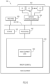
- FIG. 7 is a simplified block diagram illustrating example details associated with a proxy node such as a Proxy Master 700 for implementing operations described herein, according to an example embodiment.
- Proxy Master 700 may provide operations associated with a Proxy Master within a fronthaul network as discussed herein such as, for example, Proxy Master 240 of fronthaul network 200, as illustrated in FIG. 2 .
- FIG. 7 illustrates Proxy Master 700, which includes one or more processor(s) 702, one or more memory element(s) 704, a bus 706, one or more network interface element(s) 708, and storage 710.
- Memory element(s) 704 may include instructions for proxy master logic 720 and master link auto-negotiation logic 722.
- Memory element(s) 704 may also include a CPRI link bit rate options table 724.
- processor(s) 702 is/are at least one hardware processor configured to execute various tasks, operations, and/or functions for Proxy Master 700 according to software and/or instructions configured for Proxy Master 700.
- memory element(s) 704 is/are configured to store data, information, software and/or instructions associated with Proxy Master 700 and logic configured for memory element(s) 704.
- bus 706 can be configured as an interface that enables one or more elements of Proxy Master 700 (e.g., network interface element(s) 708, processor(s) 702, memory element(s) 704 (and logic, etc. configured therein), etc.) to communicate in order to exchange information and/or data, to perform operations, etc.
- a fast kernel-hosted interconnect may be employed for Proxy Master 700, potentially using shared memory between processes (e.g., logic, etc.), which can enable efficient communication paths between the processes.
- network interface element(s) 708 enables communications (wired or wireless) between Proxy Master 700 and other network elements or nodes, via one or more input/output (I/O) elements 712 (e.g., any number/combination of CPRI ports, Ethernet ports, transceivers, etc.) at which data, information, etc. is received and transmitted to facilitate operations discussed for various embodiments described herein.
- I/O input/output
- network interface element(s) 708 can be configured to include any combination of Ethernet interface elements, CPRI interface elements, Radio Frequency (RF) interface elements (e.g., for WiFi or any other unlicensed spectrum communications, for 3GPP or any other licensed spectrum communications, and/or or any other similar network interface elements to enable communications (e.g., CPRI bit stream/RoE frame mapping/de-mapping, Ethernet frame encapsulation/de-encapsulation, etc.) for Proxy Master 700 within a fronthaul network (e.g., fronthaul network 200).
- Proxy Master 700 can include any suitable interfaces for receiving, transmitting, and/or otherwise communicating data and/or information in a network environment.
- storage 710 can be configured to store data, information and/or instructions associated with Proxy Master 700 and/or logic configured for memory element(s) 704. Note that in certain examples, storage 710 can be consolidated with memory elements 704 (or vice versa), and/or the storage/memory elements can overlap/exist in any other suitable manner.
- CPRI link bit rate options table 724 may include a table in which each of a given value that is to be associated with each of a given CPRI link bit rate option for each of a CPRI link bit rate that may be used or supported within a fronthaul network (e.g., each of values 1-11 associated with each of 1-11 CPRI link bit rate options for each of 1-11 supported CPRI link bit rates as prescribed by CPRI Specification v7.0).
- proxy master logic 720 can include instructions that, when executed (e.g., by processor(s) 702) cause Proxy Master 700 to perform operations, which can include, but not be limited to: performing control, management, etc. operations associated with Proxy Master 700 (e.g., for CPRI bit steam/RoE frame mapping/de-mapping operations, Ethernet frame encapsulations/de-encapsulations, monitoring operations, and/or any other normal operations); cooperating and/or interacting with other logic (internal and/or external to Proxy Master 700) and/or network interface element(s) 708 (e.g., for CPRI bit stream/RoE frame mapping/de-mapping operations, Ethernet frame encapsulations/de-encapsulations, monitoring operations, and/or any other normal operations); maintaining and/or interacting with stored data, information, and/or parameters (e.g., link bit rates); combinations thereof; and/or the like to facilitate operations as discussed for various embodiments described herein.
- operations can include, but not be limited to: performing control, management
- master link auto-negotiation logic 722 may include instructions that, when executed (e.g., by processor(s) 702) may facilitate various link auto-negotiation operations described herein including, but not limited to: operations associated with link auto-negotiations performed by a Proxy Master described herein; determining a link bit rate based on link bit rate information included in an RoE header; cooperating and/or interacting with other logic (internal and/or external to Proxy Master 700) and/or network interface element(s) 708; maintaining and/or interacting with stored data, information, and/or parameters; combinations thereof; and/or the like to facilitate operations as discussed for various embodiments described herein.
- memory element(s) 704 may include any suitable memory element such as random access memory (RAM), dynamic RAM (DRAM), static RAM (SRAM), and/or cache memory.
- RAM random access memory
- DRAM dynamic RAM
- SRAM static RAM
- cache memory any suitable volatile or non-volatile computer readable storage media, which may be inclusive of non-transitory tangible media and/or non-transitory computer readable storage media that is capable of storing program/logic/software instructions and/or digital information.
- storage 710 may include any suitable storage such as persistent storage, which may be a magnetic disk drive, a solid state hard drive, a semiconductor storage device, read only memory (ROM), an erasable programmable read only memory (EPROM), flash memory, or any other computer readable storage media, which may be inclusive of non-transitory tangible media and/or non-transitory computer readable storage media, that is capable of storing program/logic/software instructions and/or digital information.
- the media used by storage 710 may also be removable.
- a removable hard drive may be used for storage 710.
- Other examples include optical and magnetic disks, thumb drives, and smart cards that are inserted into a drive for transfer onto another computer readable storage medium that is also part of storage 710.
- FIG. 8 is a simplified block diagram illustrating example details associated with a proxy node such as a Proxy Slave 800 for implementing operations described herein, according to an example embodiment.
- Proxy Slave 800 may provide operations associated with a Proxy Slave within a fronthaul network as discussed herein such as, for example, Proxy Slave 230 of fronthaul network 200, as illustrated in FIG. 2 .
- FIG. 8 illustrates Proxy Slave 800, which includes one or more processor(s) 802, one or more memory element(s) 804, a bus 806, one or more network interface element(s) 808, and storage 810.
- Memory element(s) 804 may include instructions for proxy slave logic 820 and slave link auto-negotiation logic 822.
- processor(s) 802 is/are at least one hardware processor configured to execute various tasks, operations, and/or functions for Proxy Slave 800 according to software and/or instructions configured for Proxy Slave 800.
- memory element(s) 804 is/are configured to store data, information, software and/or instructions associated with Proxy Slave 800 and logic configured for memory element(s) 804.
- bus 806 can be configured as an interface that enables one or more elements of Proxy Slave 800 (e.g., network interface element(s) 808, processor(s) 802, memory element(s) 804 (and logic etc. configured therein), etc.) to communicate in order to exchange information and/or data, to perform operations, etc.
- a fast kernel-hosted interconnect may be employed for Proxy Slave 800, potentially using shared memory between processes (e.g., logic, etc.), which can enable efficient communication paths between the processes.
- network interface element(s) 808 enables communications (wired or wireless) between Proxy Slave 800 and other network elements or nodes, via one or more input/output (I/O) elements 812 (e.g., any number/combination of CPRI ports, Ethernet ports, transceivers, etc.) at which data, information, etc. is received and transmitted to facilitate operations discussed for various embodiments described herein.
- I/O input/output
- network interface element(s) 808 can be configured to include any combination of Ethernet interface elements, CPRI interface elements, RF interface elements (e.g., for WiFi or any other unlicensed spectrum communications, for 3GPP or any other licensed spectrum communications, and/or or any other similar network interface elements to enable communications (e.g., CPRI bit stream/RoE frame mapping/de-mapping, etc.) for Proxy Slave 800 within a fronthaul network (e.g., fronthaul network 200).
- Proxy Slave 800 can include any suitable interfaces for receiving, transmitting, and/or otherwise communicating data and/or information in a network environment.
- storage 810 can be configured to store data, information and/or instructions associated with Proxy Slave 800 and/or logic configured for memory element(s) 804. Note that in certain examples, storage 810 can be consolidated with memory elements 804 (or vice versa), and/or the storage/memory elements can overlap/exist in any other suitable manner.
- CPRI link bit rate options table 824 may include a table in which each of a given value that is to be associated with each of a given CPRI link bit rate option for each of a CPRI link bit rate that may be used or supported within a fronthaul network (e.g., each of values 1-11 associated with each of 1-11 CPRI link bit rate options for each of 1-11 supported CPRI link bit rates as prescribed by CPRI Specification v7.0).
- proxy slave logic 820 can include instructions that, when executed (e.g., by processor(s) 802) cause Proxy Slave 800 to perform operations, which can include, but not be limited to: performing control, management, etc. operations associated with Proxy Slave 800 (e.g., for CPRI bit steam/RoE frame mapping/de-mapping operations, Ethernet frame encapsulations/de-encapsulations, monitoring operations, and/or any other normal operations); cooperating and/or interacting with other logic (internal and/or external to Proxy Slave 800) and/or network interface element(s) 808 (e.g., for CPRI bit stream/RoE frame mapping/de-mapping operations, Ethernet frame encapsulations/de-encapsulations, monitoring operations, and/or any other normal operations); maintaining and/or interacting with stored data, information, and/or parameters (e.g., link bit rates); combinations thereof; and/or the like to facilitate operations as discussed for various embodiments described herein.
- processor(s) 802 cause Pr
- slave link auto-negotiation logic 822 may include instructions that, when executed (e.g., by processor(s) 802) may facilitate various link auto-negotiation operations described herein including, but not limited to: operations associated with link auto-negotiations performed by a Proxy Slave described herein; including link bit rate information within RoE headers of RoE frames during link auto-negotiation operations, not including link bit rate information within RoE headers of RoE frames when link auto-negotiation operations are complete; cooperating and/or interacting with other logic (internal and/or external to Proxy Slave 800) and/or network interface element(s) 808; maintaining and/or interacting with stored data, information, and/or parameters; combinations thereof; and/or the like to facilitate operations as discussed for various embodiments described herein.
- memory element(s) 804 may include any suitable memory element such as RAM, DRAM, SRAM, and/or cache memory.
- memory element(s) 804 can include any suitable volatile or non-volatile computer readable storage media, which may be inclusive of non-transitory tangible media and/or non-transitory computer readable storage media that is capable of storing program/logic/software instructions and/or digital information.
- storage 810 may include any suitable storage such as persistent storage, which may be a magnetic disk drive, a solid state hard drive, a semiconductor storage device, ROM, an EPROM, flash memory, or any other computer readable storage media, which may be inclusive of non-transitory tangible media and/or non-transitory computer readable storage media, that is capable of storing program/logic/software instructions and/or digital information.
- the media used by storage 810 may also be removable.
- a removable hard drive may be used for storage 810.
- Other examples include optical and magnetic disks, thumb drives, and smart cards that are inserted into a drive for transfer onto another computer readable storage medium that is also part of storage 810.
- FIG. 9 is a simplified block diagram illustrating example details associated with a radio equipment controller 900 for implementing operations described herein, according to an example embodiment.
- radio equipment controller 900 may provide operations associated with a radio equipment controller within a fronthaul network as discussed herein such as, for example, REC 210 of fronthaul network 200, as illustrated in FIG. 2 .
- radio equipment controller 900 which includes one or more processor(s) 902, one or more memory element(s) 904, a bus 906, one or more network interface element(s) 908, and storage 910.
- Memory element(s) 904 may include instructions for radio equipment controller logic 920.
- processor(s) 902 is/are at least one hardware processor configured to execute various tasks, operations, and/or functions for radio equipment controller 900 according to software and/or instructions configured for radio equipment controller 900.
- memory element(s) 904 is/are configured to store data, information, software and/or instructions associated with radio equipment controller 900 and logic configured for memory element(s) 904.
- bus 906 can be configured as an interface that enables one or more elements of radio equipment controller 900 (e.g., network interface element(s) 908, processor(s) 902, memory element(s) 904 (and logic etc. configured therein), etc.) to communicate in order to exchange information and/or data, to perform operations, etc.
- a fast kernel-hosted interconnect may be employed for radio equipment controller 900, potentially using shared memory between processes (e.g., logic, etc.), which can enable efficient communication paths between the processes.
- network interface element(s) 908 enables communications (wired or wireless) between radio equipment controller 900 and other network elements or nodes, via one or more input/output (I/O) elements 912 (e.g., any number/combination of CPRI ports, Ethernet ports, transceivers, etc.) at which data, information, etc. is received and transmitted to facilitate operations discussed for various embodiments described herein.
- I/O input/output
- network interface element(s) 908 can be configured to include Ethernet interface elements, CPRI interface elements, RF interface elements (e.g., for WiFi or any other unlicensed spectrum communications, for 3GPP or any other licensed spectrum communications, and/or or any other similar network interface elements to enable communications for radio equipment controller 900 within a fronthaul network (e.g., fronthaul network 200).
- Radio equipment controller 900 can include any suitable interfaces for receiving, transmitting, and/or otherwise communicating data and/or information in a network environment.
- storage 910 can be configured to store data, information and/or instructions associated with radio equipment controller 900 and/or logic configured for memory element(s) 904. Note that in certain examples, storage 910 can be consolidated with memory elements 904 (or vice versa), and/or the storage/memory elements can overlap/exist in any other suitable manner.
- radio equipment controller logic 920 can include instructions that, when executed (e.g., by processor(s) 902) cause radio equipment controller 900 to perform operations, which can include, but not be limited to: performing control, management, etc. operations associated with radio equipment controller 900 (e.g., CPRI link negotiation operations, radio equipment controller operations, and/or any other normal operations); cooperating and/or interacting with other logic (internal and/or external to radio equipment controller 900) and/or network interface element(s) 908 (e.g., for CPRI link negotiation operations, radio equipment controller operations, and/or any other normal operations); maintaining and/or interacting with stored data, information, and/or parameters (e.g., link bit rates); combinations thereof; and/or the like to facilitate operations as discussed for various embodiments described herein.
- operations can include, but not be limited to: performing control, management, etc. operations associated with radio equipment controller 900 (e.g., CPRI link negotiation operations, radio equipment controller operations, and/or any other normal operations); cooperating and/or interacting
- memory element(s) 904 may include any suitable memory element such as RAM, DRAM, SRAM, and/or cache memory.
- memory element(s) 904 can include any suitable volatile or non-volatile computer readable storage media, which may be inclusive of non-transitory tangible media and/or non-transitory computer readable storage media that is capable of storing program/logic/software instructions and/or digital information.
- storage 910 may include any suitable storage such as persistent storage, which may be a magnetic disk drive, a solid state hard drive, a semiconductor storage device, ROM, EPROM, flash memory, or any other computer readable storage media, which may be inclusive of non-transitory tangible media and/or non-transitory computer readable storage media, that is capable of storing program/logic/software instructions and/or digital information.
- the media used by storage 910 may also be removable.
- a removable hard drive may be used for storage 910.
- Other examples include optical and magnetic disks, thumb drives, and smart cards that are inserted into a drive for transfer onto another computer readable storage medium that is also part of storage 910.
- FIG. 10 is a simplified block diagram illustrating example details associated with a radio equipment 1000 for implementing operations described herein, according to an example embodiment.
- radio equipment 1000 may provide operations associated with radio equipment within a fronthaul network as discussed herein such as, for example, RE 220 of fronthaul network 200, as illustrated in FIG. 2 .
- FIG. 10 illustrates radio equipment 1000, which includes one or more processor(s) 1002, one or more memory element(s) 1004, a bus 1006, one or more network interface element(s) 1008, storage 1010, and a radio head 1030.
- Memory element(s) 1004 may include instructions for radio equipment logic 1020.
- radio head 1030 can include circuitry, hardware, antennas, software, firmware, combinations thereof, and/or the like to provide one or more radio transmitters and receivers to facilitate over-the-air radio access connectivity for user equipment.
- processor(s) 1002 is/are at least one hardware processor configured to execute various tasks, operations, and/or functions for radio equipment 1000 according to software and/or instructions configured for radio equipment 1000.
- memory element(s) 1004 is/are configured to store data, information, software and/or instructions associated with radio equipment 1000 and logic configured for memory element(s) 1004.
- bus 1006 can be configured as an interface that enables one or more elements of radio equipment 1000 (e.g., network interface element(s) 1008, processor(s) 1002, memory element(s) 1004 (and logic, etc. configured therein), radio head 1030, etc.) to communicate in order to exchange information and/or data, to perform operations, etc.
- a fast kernel-hosted interconnect may be employed for radio equipment 1000, potentially using shared memory between processes (e.g., logic, etc.), which can enable efficient communication paths between the processes.
- network interface element(s) 1008 enables communications (wired or wireless) between radio equipment 1000 and other network elements or nodes, via one or more input/output (I/O) elements 1012 (e.g., any number/combination of CPRI ports, Ethernet ports, transceivers, etc.) at which data, information, etc. is received and transmitted to facilitate operations discussed for various embodiments described herein.
- I/O input/output
- network interface element(s) 1008 can be configured to include Ethernet interface elements, CPRI interface elements, RF interface elements (e.g., for WiFi or any other unlicensed spectrum communications, for 3GPP or any other licensed spectrum communications, and/or or any other similar network interface elements to enable communications for radio equipment 1000 within a fronthaul network (e.g., fronthaul network 200).
- Radio equipment 1000 can include any suitable interfaces for receiving, transmitting, and/or otherwise communicating data and/or information in a network environment.
- storage 1010 can be configured to store data, information and/or instructions associated with radio equipment 1000 and/or logic configured for memory element(s) 1004. Note that in certain examples, storage 1010 can be consolidated with memory elements 1004 (or vice versa), and/or the storage/memory elements can overlap/exist in any other suitable manner.
- radio equipment logic 1020 can include instructions that, when executed (e.g., by processor(s) 1002) cause radio equipment 1000 to perform operations, which can include, but not be limited to: performing control, management, etc. operations associated with radio equipment 1000 (e.g., CPRI link negotiation operations, radio equipment operations, and/or any other normal operations); cooperating and/or interacting with other logic (internal and/or external to radio equipment 1000) and/or network interface element(s) 1008 (e.g., for CPRI link negotiation operations, radio equipment operations, and/or any other normal operations); maintaining and/or interacting with stored data, information, and/or parameters (e.g., link bit rates); combinations thereof; and/or the like to facilitate operations as discussed for various embodiments described herein.
- operations can include, but not be limited to: performing control, management, etc. operations associated with radio equipment 1000 (e.g., CPRI link negotiation operations, radio equipment operations, and/or any other normal operations); cooperating and/or interacting with other logic (internal and/or external to
- memory element(s) 1004 may include any suitable memory element such as RAM, DRAM, SRAM, and/or cache memory.
- memory element(s) 1004 can include any suitable volatile or non-volatile computer readable storage media, which may be inclusive of non-transitory tangible media and/or non-transitory computer readable storage media that is capable of storing program/logic/software instructions and/or digital information.
- storage 1010 may include any suitable storage such as persistent storage, which may be a magnetic disk drive, a solid state hard drive, a semiconductor storage device, ROM, an EPROM, flash memory, or any other computer readable storage media, which may be inclusive of non-transitory tangible media and/or non-transitory computer readable storage media, that is capable of storing program/logic/software instructions and/or digital information.
- the media used by storage 1010 may also be removable.
- a removable hard drive may be used for storage 1010.
- Other examples include optical and magnetic disks, thumb drives, and smart cards that are inserted into a drive for transfer onto another computer readable storage medium that is also part of storage 1010.
- MIMO Multiple-Input Multiple-Output
- IEEE 1914.1 and IEEE 1914.3 Specifications are the standards for packet based fronthaul transport networks; these standards do not cover how end-to-end link negotiations can happen between REC and RE in the fronthaul networks.
- Embodiments herein provide techniques to solve this above gap. For example, a network operator can deploy CPRI-based REC and/or RE units of varied capabilities in fronthaul network and the techniques discussed for embodiments herein can be used to achieve end-to-end CPRI link synchronization, which otherwise would require static manual configurations at each CPRI interface which is error prone, inefficient at times, and not scalable.
- a computer-implemented method may include performing, for one or more link bit rates of a plurality of link bit rates configured for a fronthaul network, Common Public Radio Interface (CPRI) Layer 1 link auto-negotiation operations to establish a CPRI link between a radio equipment controller and a radio equipment of the fronthaul network, the CPRI Layer 1 link auto-negotiation operations comprising: achieving, by a proxy slave, a hyper frame number synchronization with the radio equipment controller at a link bit rate for a first CPRI bit stream transmitted by the radio equipment controller; communicating the first CPRI bit stream and the link bit rate from the proxy slave to a proxy master; transmitting, by the proxy master, the first CPRI bit stream to the radio equipment at the link bit rate and the radio equipment attempting to achieve a hyper frame number synchronization with the first CPRI bit stream; upon the radio equipment achieving the hyper frame number synchronization, the radio equipment communicating a second CPRI bit stream to the proxy master at the link bit rate; upon the proxy
- CPRI Common Public
- the method may include, upon achieving the hyper frame number synchronization with the radio equipment controller, the proxy slave does not transmit to the radio equipment controller until the second CPRI bit stream is received from the proxy master.
- the first CPRI bit steam and the link bit rate are communicated from the proxy slave to the proxy master and the second CPRI bit stream is communicated from the proxy master to the proxy slave using an Ethernet network.
- the method may further include, upon the Layer 1 link auto-negotiation operations being completed, the proxy slave does not communicate the link bit rate to the proxy master.
- the CPRI Layer 1 link auto-negotiation operations are performed within one transmit time interval of the radio equipment controller.
- the CPRI Layer 1 link auto-negotiation operations may be repeated with the plurality of link bit rates until the radio equipment controller achieves the hyper frame number synchronization for the second CPRI bit stream transmitted by the proxy slave at the particular link bit rate.
- communicating the link bit rate includes communicating a value indicating a link bit rate option associated with the link bit rate.
- the value indicating the link bit rate option is included within a header of a Radio over Ethernet (RoE) frame that is encapsulated within an Ethernet frame.
- the value indicating the link bit rate option is included within a sequence number field of the header.
- the value indicating the link bit rate option is included within one to four bits of a sequence number field of the header.
- the value indicating link bit rate option is included within a 4-bit sequence number field of the header and a zero value of the 4-bit sequence number is not used.
- another computer-implemented method may include determining, by a first proxy node, Common Public Radio Interface (CPRI) link bit rate information to communicate from the first proxy node to a second proxy node; providing the CPRI link bit rate information within a header of a Radio over Ethernet (RoE) frame; and communicating the RoE frame to the second proxy node.
- the RoE frame can be encapsulated within an Ethernet frame.
- the CPRI link bit rate information is a value indicating a CPRI link bit rate option associated with a CPRI link bit rate at which the first proxy node has achieved a hyper frame number synchronization for a CPRI bit stream received by the first proxy node.
- the value is provided within a reserved bits field of a sequence number field of the header.
- Data relating to operations described herein may be stored within any conventional or other data structures (e.g., files, arrays, lists, stacks, queues, records, etc.) and may be stored in any desired storage unit (e.g., database, data or other repositories, queue, etc.).
- the data transmitted between entities may include any desired format and arrangement, and may include any quantity of any types of fields of any size to store the data.
- the definition and data model for any datasets may indicate the overall structure in any desired fashion (e.g., computer-related languages, graphical representation, listing, etc.).
- the environment of the present embodiments may include any number of computer, compute node, network element, or other processing systems (e.g., client or end-user systems, server systems, etc.) and databases or other repositories arranged in any desired fashion, where the present embodiments may be applied to any desired type of computing environment (e.g., cloud computing, client-server, network computing, mainframe, stand-alone systems, etc.).
- the computer or other processing systems employed by the present embodiments may be implemented by any number of any personal or other type of computer or processing system (e.g., desktop, laptop, personal digital assistant (PDA), mobile devices, etc.), and may include any commercially available operating system and any combination of commercially available and custom software (e.g., machine learning software, etc.).
- PDA personal digital assistant
- These systems may include any types of monitors and input/output devices (e.g., keyboard, mouse, voice recognition, etc.) to enter and/or view information.
- operations as outlined herein may be implemented by logic encoded in one or more tangible media, which may be inclusive of non-transitory tangible media and/or non-transitory computer readable storage media (e.g., embedded logic provided in an application specific integrated circuit (ASIC), a field programmable gate array (FPGA), in digital signal processing (DSP) instructions, firmware, software [potentially inclusive of object code and source code] to be executed by a processor, or other similar machine, etc.).
- ASIC application specific integrated circuit
- FPGA field programmable gate array
- DSP digital signal processing
- firmware software [potentially inclusive of object code and source code] to be executed by a processor, or other similar machine, etc.
- a memory element or storage can store data used for operations described herein. This includes memory elements or storage being able to store software, logic, code, and/or processor instructions that are executed to carry out operations described herein.
- a processor e.g., a hardware processor
- a processor may transform an element or an article (e.g., data, information) from one state or thing to another state or thing.
- operations outlined herein may be implemented with logic, which can include fixed logic, hardware logic, programmable logic, digital logic, etc.
- programmable processor e.g., software/computer instructions executed by a processor
- programmable digital logic e.g., an FPGA, a DSP processor, an EPROM, a controller, an electrically erasable PROM (EEPROM), or an ASIC that includes digital logic, software, firmware, code, electronic instructions, or any suitable combination thereof.
- a network element can encompass network appliances, routers, servers, switches, gateways, bridges, load balancers, firewalls, processors, modules, or any other suitable device, component, element, or object operable to exchange information that facilitates or otherwise helps to facilitate various operations as described for various embodiments discussed herein in a network environment (e.g., for networks such as discussed herein).
- Elements and/or systems discussed for various embodiments described herein can couple to one another through simple interfaces and/or through any other suitable connection (wired or wireless), which provides a viable pathway for network communications.
- a physical (wired or wireless) interconnection or interface can refer to an interconnection of one element with one or more other element(s), while a logical interconnection or interface can refer to communications, interactions and/or operations of elements with each other, which can be directly or indirectly interconnected, in a network environment.
- any one or more of the elements and/or systems may be combined or removed from a given deployment based on a particular configuration and/or implementation.
- networks can represent a series of points or elements of interconnected communication paths (wired or wireless) for receiving and transmitting packets of information that propagate through networks.
- networks can be associated with and/or provided by a single network operator or service provider and/or multiple network operators or service providers.
- networks can include and/or overlap with, in whole or in part, one or more packet data network(s).
- a network may offer communicative interfaces between various elements of the network and may be associated with any local area network (LAN), wireless local area network (WLAN), metropolitan area network (MAN), wide area network (WAN), virtual private network (VPN), Radio Access Network (RAN), virtual local area network (VLAN), enterprise network, Intranet, extranet, or any other appropriate architecture or system that facilitates communications in a network environment
- LAN local area network
- WLAN wireless local area network
- MAN metropolitan area network
- WAN wide area network
- VPN virtual private network
- RAN Radio Access Network
- VLAN virtual local area network
- enterprise network Intranet, extranet, or any other appropriate architecture or system that facilitates communications in a network environment
- Networks through which communications propagate in can use any suitable technologies for communication including wireless (e.g., 3G/4G/5G/NG network, Institute of Electrical and Electronics Engineers (IEEE) Standard 802.11 TM -2012, published March 29, 2012 (e.g., WiFi), WiMax, IEEE Standard 802.16 TM -2012, published August 17, 2012, Radio-frequency Identification (RFID), Near Field Communication (NFC), Bluetooth TM , etc.) and/or wired (e.g., T1 lines, T3 lines, digital subscriber lines (DSL), Ethernet, etc.) communication.
- wireless e.g., 3G/4G/5G/NG network, Institute of Electrical and Electronics Engineers (IEEE) Standard 802.11 TM -2012, published March 29, 2012 (e.g., WiFi), WiMax, IEEE Standard 802.16 TM -2012, published August 17, 2012, Radio-frequency Identification (RFID), Near Field Communication (NFC), Bluetooth TM , etc.
- RFID Radio-frequency Identification
- NFC Near Field Communication
- references to various features e.g., elements, structures, nodes, modules, components, logic, steps, operations, functions, characteristics, etc.
- references to various features are intended to mean that any such features are included in one or more embodiments of the present disclosure, but may or may not necessarily be combined in the same embodiments.
- a module, engine, client, controller, function, logic, or the like as used herein can be inclusive of an executable file comprising instructions that can be understood and processed on a computer, processor, machine, network element, compute node, combinations thereof, or the like and may further include library modules loaded during execution, object files, system files, hardware logic, software logic, and/or any other executable modules.
- the embodiments presented may be implemented in various forms, such as an apparatus, a system, a method, and/or a computer program product at any possible technical detail level of integration
- the computer program product may include a non-transitory computer readable storage medium (or media) having computer readable program instructions thereon for causing a processor to carry out aspects of operations presented herein.
- each of the expressions 'at least one of X, Y and Z', 'at least one of X, Y or Z', 'one or more of X, Y and Z', 'one or more of X, Y or Z' and 'A, B and/or C' can mean any of the following: 1) X, but not Y and not Z; 2) Y, but not X and not Z; 3) Z, but not X and not Y; 4) X and Y, but not Z; 5) X and Z, but not Y; 6) Y and Z, but not X; or 7) X, Y, and Z.
- the terms 'first', 'second', 'third', etc. are intended to distinguish the particular nouns (e.g., element, condition, node, module, activity, operation, etc.) they modify. Unless expressly stated to the contrary, the use of these terms is not intended to indicate any type of order, rank, importance, temporal sequence, or hierarchy of the modified noun.
- 'first X' and 'second X' are intended to designate two X elements that are not necessarily limited by any order, rank, importance, temporal sequence, or hierarchy of the two elements.
- 'at least one of and 'one or more of can be represented using the '(s)' nomenclature (e.g., one or more element(s)).
Landscapes
- Engineering & Computer Science (AREA)
- Computer Networks & Wireless Communication (AREA)
- Signal Processing (AREA)
- Quality & Reliability (AREA)
- Mobile Radio Communication Systems (AREA)
- Small-Scale Networks (AREA)
- Communication Control (AREA)
Claims (6)
- In einem Fronthaul-Netzwerk (200), das eine Funkgerätesteuerung (210), die mit einem Proxy-Slave (230) verbunden ist, einen Proxy-Master (240), der mit einem Funkgerät (220) verbunden ist, und ein Ethernet-Netzwerk (250) aufweist, das den Proxy-Master und den Proxy-Slave verbindet, ein Verfahren zum Herstellen einer Common Public Radio Interface, CPRI, - Verbindung zwischen der Funkgerätesteuerung und dem Funkgerät über das Ethernet-Netzwerk, wobei das Verfahren aufweist:Empfangen (301) eines ersten CPRI-Bitstroms, der mit einer oder mehreren ersten Verbindungsbitraten zu einer oder mehreren jeweiligen Sendezeiten übertragen wird, an dem Proxy-Slave von der Funkgerätesteuerung, und Versuchen, den ersten CPRI-Bitstrom mit einer oder mehreren zweiten Verbindungsbitraten zu einer oder mehreren jeweiligen Empfangszeiten an dem Proxy-Slave zu dekodieren, wobei die Verbindungsbitraten Leitungsbitraten sind;beim Erreichen einer Hyper-Frame-Number-Synchronisation, HFN Sync, zwischen dem Proxy-Slave und der Funkgerätesteuerung mit einer Verbindungsrate, im Folgenden als Sync-Link-Bitrate bezeichnet, Abbilden (302) des ersten CPRI-Bitstroms auf einen oder mehrere Radio-over-Ethernet-, RoE-, Frames;wobei mindestens einer der einen oder mehreren RoE-Frames einen Header aufweist, der die Sync-Link-Bitrate angibt;Übermitteln der ein oder mehreren RoE-Frames an den Proxy-Master;beim Empfangen eines oder mehrerer RoE-Frames von dem Proxy-Master, wobei der eine oder die mehreren von dem Proxy-Master empfangenen RoE-Frames einen zweiten CPRI-Bitstrom aufweisen, der von dem Funkgerät übertragen wird, De-Mapping (305) des einen oder der mehreren von dem Proxy-Master empfangenen RoE-Frames;Übertragen des zweiten CPRI-Bitstroms an die Funkgerätesteuerung mit der ersten Sync-Link-Bitrate; undwenn HFN-Sync zwischen dem Proxy-Slave und der Funkgerätesteuerung unter Verwendung der Sync-Link-Bitrate erreicht ist, Kommunikation zwischen der Funkgerätesteuerung und dem Funkgerät über die eingerichtete CPRI-Verbindung unter Verwendung der Sync-Link-Bitrate.
- Verfahren nach Anspruch 1, bei dem die CPRI-Verbindung innerhalb eines Sendezeitintervalls hergestellt wird, das zwei aufeinanderfolgende Sendezeiten der Funkgerätesteuerung trennt.
- Verfahren nach Anspruch 1, wobei das Verfahren so lange wiederholt wird, bis die Funkgerätesteuerung die HFN-Synchronisation für den zweiten CPRI-Bitstrom erreicht, der vom Proxy-Slave mit der Sync-Link-Bitrate übertragen wird
- Verfahren nach Anspruch 1, bei dem die eine oder mehrere erste und die eine oder mehrere zweite Verbindungsbitrate(n) so synchronisiert sind, dass sie eine gemeinsame Teilmenge von Verbindungsbitraten aufweisen.
- Computerlesbares Speichermedium mit darauf befindlichen computerlesbaren Programmanweisungen, um einen Prozessor zu veranlassen, das Verfahren nach einem der vorhergehenden Ansprüche auszuführen.
- Ein System, das so konfiguriert ist, dass es das Verfahren nach einem der Ansprüche 1 bis 4 durchführt.
Applications Claiming Priority (4)
| Application Number | Priority Date | Filing Date | Title |
|---|---|---|---|
| IN201941003988 | 2019-02-01 | ||
| US16/435,961 US11343781B2 (en) | 2019-02-01 | 2019-06-10 | Link establishment between a radio equipment controller (REC) and radio equipment (RE) in a fronthaul network |
| PCT/US2020/015157 WO2020159847A1 (en) | 2019-02-01 | 2020-01-27 | Link establishment between a radio equipment controller (rec) and radio equipment (re) in a fronthaul network |
| EP20708334.6A EP3918877B1 (de) | 2019-02-01 | 2020-01-27 | Verbindungsaufbau zwischen einem funkgerätesteuergerät (rec) und einem funkgerät (re) in einem fronthaul-netzwerk |
Related Parent Applications (2)
| Application Number | Title | Priority Date | Filing Date |
|---|---|---|---|
| EP20708334.6A Division-Into EP3918877B1 (de) | 2019-02-01 | 2020-01-27 | Verbindungsaufbau zwischen einem funkgerätesteuergerät (rec) und einem funkgerät (re) in einem fronthaul-netzwerk |
| EP20708334.6A Division EP3918877B1 (de) | 2019-02-01 | 2020-01-27 | Verbindungsaufbau zwischen einem funkgerätesteuergerät (rec) und einem funkgerät (re) in einem fronthaul-netzwerk |
Publications (3)
| Publication Number | Publication Date |
|---|---|
| EP4240102A2 EP4240102A2 (de) | 2023-09-06 |
| EP4240102A3 EP4240102A3 (de) | 2023-11-01 |
| EP4240102B1 true EP4240102B1 (de) | 2025-04-02 |
Family
ID=71836987
Family Applications (5)
| Application Number | Title | Priority Date | Filing Date |
|---|---|---|---|
| EP22165196.1A Active EP4040915B1 (de) | 2019-02-01 | 2020-01-27 | Automatische verbindungsverhandlung zwischen einer funkgerätesteuerung (rec) und einem funkgerät (re) in einem ethernet-basierten fronthaul-netzwerk |
| EP20708334.6A Active EP3918877B1 (de) | 2019-02-01 | 2020-01-27 | Verbindungsaufbau zwischen einem funkgerätesteuergerät (rec) und einem funkgerät (re) in einem fronthaul-netzwerk |
| EP23181923.6A Active EP4240102B1 (de) | 2019-02-01 | 2020-01-27 | Verbindungsaufbau zwischen einer funkausrüstungssteuerung (rec) und einer funkausrüstung (re) in einem fronthaul-netzwerk |
| EP20708335.3A Active EP3918878B1 (de) | 2019-02-01 | 2020-01-27 | Verbindungsaufbau zwischen einem funkgerätesteuergerät (rec) und einem funkgerät (re) in einem fronthaul-netzwerk |
| EP20707957.5A Pending EP3918876A1 (de) | 2019-02-01 | 2020-01-27 | Automatische verbindungsverhandlung zwischen einer funkgerätesteuerung (rec) und einem funkgerät (re) in einem ethernet-basierten fronthaul-netzwerk |
Family Applications Before (2)
| Application Number | Title | Priority Date | Filing Date |
|---|---|---|---|
| EP22165196.1A Active EP4040915B1 (de) | 2019-02-01 | 2020-01-27 | Automatische verbindungsverhandlung zwischen einer funkgerätesteuerung (rec) und einem funkgerät (re) in einem ethernet-basierten fronthaul-netzwerk |
| EP20708334.6A Active EP3918877B1 (de) | 2019-02-01 | 2020-01-27 | Verbindungsaufbau zwischen einem funkgerätesteuergerät (rec) und einem funkgerät (re) in einem fronthaul-netzwerk |
Family Applications After (2)
| Application Number | Title | Priority Date | Filing Date |
|---|---|---|---|
| EP20708335.3A Active EP3918878B1 (de) | 2019-02-01 | 2020-01-27 | Verbindungsaufbau zwischen einem funkgerätesteuergerät (rec) und einem funkgerät (re) in einem fronthaul-netzwerk |
| EP20707957.5A Pending EP3918876A1 (de) | 2019-02-01 | 2020-01-27 | Automatische verbindungsverhandlung zwischen einer funkgerätesteuerung (rec) und einem funkgerät (re) in einem ethernet-basierten fronthaul-netzwerk |
Country Status (3)
| Country | Link |
|---|---|
| US (7) | US11395242B2 (de) |
| EP (5) | EP4040915B1 (de) |
| WO (3) | WO2020159846A1 (de) |
Families Citing this family (16)
| Publication number | Priority date | Publication date | Assignee | Title |
|---|---|---|---|---|
| US11412528B2 (en) * | 2016-11-03 | 2022-08-09 | Samsung Electronics Co., Ltd. | Method and device for supporting latency services via a logical channel in a mobile communication system |
| CN109587782B (zh) * | 2017-09-28 | 2021-04-30 | 中兴通讯股份有限公司 | 一种同步方法和装置 |
| US11395242B2 (en) * | 2019-02-01 | 2022-07-19 | Cisco Technology, Inc. | Link establishment between a radio equipment controller (REC) and radio equipment (RE) in a fronthaul network |
| EP4000305A4 (de) * | 2019-07-19 | 2023-03-29 | Telefonaktiebolaget LM Ericsson (publ) | Verfahren und vorrichtungen zur kommunikation zwischen funkgerät und funkgerätesteuerung |
| US10594423B1 (en) * | 2019-09-09 | 2020-03-17 | Cisco Technology, Inc. | Re-timing a packetized radio flow to clean noise induced by packet delay variation of a packet network |
| WO2021087875A1 (en) * | 2019-11-07 | 2021-05-14 | Telefonaktiebolaget Lm Ericsson (Publ) | Method and apparatus for communication between two communication devices |
| US11388080B2 (en) * | 2020-01-23 | 2022-07-12 | CoMIRA Solutions Inc. | Detecting false linkup states in Ethernet communication links |
| WO2021215975A1 (en) * | 2020-04-22 | 2021-10-28 | Telefonaktiebolaget Lm Ericsson (Publ) | Configuring fronthaul link |
| CN114125881B (zh) | 2020-08-28 | 2024-09-03 | 深圳市中兴微电子技术有限公司 | 接口数据的处理方法、发送端设备和接收端设备 |
| CN116195234A (zh) * | 2020-09-23 | 2023-05-30 | 瑞典爱立信有限公司 | 用于在光网络中自动配置端口的方法和装置 |
| US11924795B2 (en) * | 2021-11-30 | 2024-03-05 | Qualcomm Incorporated | Ethernet protocol data unit (PDU) session—hyper frame number (HFN) resync |
| CN116684993A (zh) * | 2022-02-22 | 2023-09-01 | 华为技术有限公司 | 一种自适应建立链路的方法,基带单元和无线电单元 |
| US20250202830A1 (en) * | 2022-03-17 | 2025-06-19 | Telefonaktiebolaget Lm Ericsson (Publ) | Method and apparatus for detecting and reordering disorder packets |
| US12438830B2 (en) | 2022-05-25 | 2025-10-07 | Cisco Technology, Inc. | Providing high assurance of end-to-end CPRI circuit in a high jitter packet based fronthaul network |
| CN115915045B (zh) * | 2022-11-08 | 2023-09-22 | 之江实验室 | 一种用于降低用户面和控制面信令交互负载的方法及装置 |
| US20240381129A1 (en) * | 2023-05-08 | 2024-11-14 | Dish Wireless L.L.C. | Monitoring a fronthaul interface of a network |
Family Cites Families (47)
| Publication number | Priority date | Publication date | Assignee | Title |
|---|---|---|---|---|
| TWI220610B (en) * | 2002-05-24 | 2004-08-21 | Realtek Semiconductor Corp | Method and device for setting the autonegotiation mode of a repeater |
| SE0301053D0 (sv) * | 2003-04-07 | 2003-04-07 | Ericsson Telefon Ab L M | Method and system in a communications network |
| US20040208180A1 (en) * | 2003-04-15 | 2004-10-21 | Light Allen Miles | System and method for supporting auto-negotiation among standards having different rates |
| US7630631B2 (en) | 2004-04-14 | 2009-12-08 | Finisar Corporation | Out-of-band data communication between network transceivers |
| US7916676B2 (en) | 2007-03-23 | 2011-03-29 | Broadcom Corporation | Method and system for holistic energy management in ethernet networks |
| GB2455702B (en) * | 2007-11-29 | 2012-05-09 | Ubidyne Inc | A method and apparatus for autonomous port role assignments in master-slave networks |
| US8050296B2 (en) * | 2008-03-31 | 2011-11-01 | Telefonaktiebolaget Lm Ericsson (Publ) | Radio equipment (RE)-based synchronization |
| JP5187443B2 (ja) | 2009-05-27 | 2013-04-24 | 富士通株式会社 | 無線装置制御装置、無線装置、および通信方法 |
| CN101931454B (zh) * | 2009-06-19 | 2013-06-05 | 大唐移动通信设备有限公司 | 基于以太网的射频拉远数据传输 |
| JP5193990B2 (ja) | 2009-12-17 | 2013-05-08 | 株式会社エヌ・ティ・ティ・ドコモ | 中継装置 |
| CN102118191B (zh) * | 2010-01-06 | 2014-01-08 | 华为技术有限公司 | 一种通用公共无线接口数据的传递方法、设备及系统 |
| KR101674209B1 (ko) | 2010-01-27 | 2016-11-08 | 삼성전자주식회사 | 디지털 장치와 rf 장치간에 이더넷 데이터를 송수신하는 방법 및 그 장치 |
| US8649388B2 (en) | 2010-09-02 | 2014-02-11 | Integrated Device Technology, Inc. | Transmission of multiprotocol data in a distributed antenna system |
| WO2012171133A1 (en) | 2011-06-13 | 2012-12-20 | Telefonaktiebolaget L M Ericsson (Publ) | Method and device for rate matching |
| US8599827B2 (en) | 2011-10-21 | 2013-12-03 | Telefonaktiebolaget Lm Ericsson (Publ) | Methods and apparatuses for maintaining synchronization between a radio equipment controller and an item of radio equipment |
| CA2864279C (en) | 2012-02-09 | 2019-06-11 | Telefonaktiebolaget Lm Ericsson (Publ) | A network node and a method therein enabling a first unit to connect or to be connected ad-hoc to a second unit |
| US8964641B2 (en) | 2012-06-10 | 2015-02-24 | Cisco Technology, Inc. | System and method for transporting digital baseband streams in a network environment |
| US9838217B2 (en) | 2012-06-20 | 2017-12-05 | Telefonaktiebolaget Lm Ericsson (Publ) | Encapsulating CPRI frames |
| EP2685645B1 (de) * | 2012-07-09 | 2016-04-27 | Alcatel Lucent | Verfahren und Vorrichtung zum Verarbeiten von digitalen Datenrahmen und Transportrahmen zum Reduzieren der Transportbandbreite |
| EP2893657B1 (de) | 2012-09-06 | 2019-06-26 | Telefonaktiebolaget LM Ericsson (publ) | Verwendung öffentlicher allgemeiner funkschnittstellen über asymmetrische netzwerke |
| JP2014096633A (ja) | 2012-11-07 | 2014-05-22 | Nec Saitama Ltd | 同期窓自動設定方法、無線通信システム、無線制御装置および同期窓自動設定プログラム |
| US9313827B2 (en) | 2012-12-31 | 2016-04-12 | Broadcom Corporation | Radio over ethernet for radio access network and cloud-RAN |
| US9014052B2 (en) | 2013-01-14 | 2015-04-21 | Andrew Llc | Interceptor system for characterizing digital data in telecommunication system |
| US9277424B2 (en) * | 2013-02-28 | 2016-03-01 | Keysight Technologies, Inc. | Method and apparatus for determining the configuration of a cellular transmission system |
| US9736274B2 (en) | 2013-11-14 | 2017-08-15 | Avago Technologies General Ip (Singapore) Pte. Ltd. | Radio over ethernet mapper physical layer device (PHY) |
| US9204312B2 (en) | 2013-11-27 | 2015-12-01 | Freescale Semiconductor, Inc. | Method for adding leaf node to multi-node base station |
| US20160277964A1 (en) | 2013-12-13 | 2016-09-22 | Telefonaktiebolaget L M Ericsson (Publ) | Devices and methods for multiplexing and demultiplexing common public radio interface data streams |
| US9749050B2 (en) * | 2014-02-18 | 2017-08-29 | Avago Technologies General Ip (Singapore) Pte. Ltd. | CPRI framelets |
| US9521636B2 (en) * | 2014-04-22 | 2016-12-13 | Nxp Usa, Inc. | Synchronization circuitry, common public radio interface enable device, and a method of synchronizing a synchronized clock signal of a second transceiver to a clock of a first transceiver |
| US9848379B2 (en) | 2014-09-22 | 2017-12-19 | Telefonaktiebolaget Lm Ericsson (Publ) | Cascaded radio communication system |
| CN105871502B (zh) | 2015-01-22 | 2020-01-03 | 华为技术有限公司 | 一种利用以太网信道传输业务信号的方法及通信设备 |
| US9491758B2 (en) * | 2015-04-07 | 2016-11-08 | Freescale Semiconductor, Inc. | System for alignment of RF signals |
| CN106162860B (zh) | 2015-04-27 | 2020-01-03 | 华为技术有限公司 | 一种时间同步的方法及系统、网络设备 |
| WO2017035724A1 (zh) | 2015-08-31 | 2017-03-09 | 华为技术有限公司 | 接收cpri数据流和接收以太网帧的方法、装置及系统 |
| US10044471B2 (en) | 2015-09-01 | 2018-08-07 | IPLight Ltd. | Delivering CPRI and ethernet signals over optical networks |
| JP2017085473A (ja) | 2015-10-30 | 2017-05-18 | 富士通株式会社 | 伝送システム、無線装置および同期確立方法 |
| CN107547481B (zh) | 2016-06-28 | 2021-09-24 | 中兴通讯股份有限公司 | 数据传输方法和装置以及光电转换装置和系统 |
| US10524273B2 (en) | 2016-09-06 | 2019-12-31 | Telefonaktiebolaget Lm Ericsson (Publ) | Resource configuration of wireless devices |
| US10165459B2 (en) | 2016-09-07 | 2018-12-25 | Verizon Patent And Licensing Inc. | Remote monitoring of fronthaul radio signals |
| WO2018104175A1 (en) | 2016-12-06 | 2018-06-14 | Telefonaktiebolaget Lm Ericsson (Publ) | Method and apparatus for latency monitoring |
| CN109997383B (zh) | 2016-12-09 | 2021-09-07 | 华为技术有限公司 | 协议转换方法及装置 |
| WO2018189726A1 (en) | 2017-04-13 | 2018-10-18 | Telefonaktiebolaget Lm Ericsson (Publ) | Distributed scheduling algorithm for cpri over ethernet |
| US10313917B2 (en) | 2017-04-24 | 2019-06-04 | Huawei Technologies Co., Ltd. | UE load-sensitive front-haul controller |
| PT3677093T (pt) | 2017-08-31 | 2021-04-06 | Ericsson Telefon Ab L M | Métodos, unidades rádio intermédias e terminais rádio de sistemas de estação base para transmissão de portadoras de antena |
| US10785082B2 (en) | 2018-09-19 | 2020-09-22 | Solid, Inc. | Distributed antenna system-based on time sensitive network |
| US11395242B2 (en) * | 2019-02-01 | 2022-07-19 | Cisco Technology, Inc. | Link establishment between a radio equipment controller (REC) and radio equipment (RE) in a fronthaul network |
| EP4000305A4 (de) * | 2019-07-19 | 2023-03-29 | Telefonaktiebolaget LM Ericsson (publ) | Verfahren und vorrichtungen zur kommunikation zwischen funkgerät und funkgerätesteuerung |
-
2019
- 2019-06-10 US US16/435,974 patent/US11395242B2/en active Active
- 2019-06-10 US US16/435,961 patent/US11343781B2/en active Active
- 2019-06-10 US US16/435,946 patent/US11228991B2/en active Active
-
2020
- 2020-01-27 EP EP22165196.1A patent/EP4040915B1/de active Active
- 2020-01-27 WO PCT/US2020/015156 patent/WO2020159846A1/en not_active Ceased
- 2020-01-27 WO PCT/US2020/015157 patent/WO2020159847A1/en not_active Ceased
- 2020-01-27 EP EP20708334.6A patent/EP3918877B1/de active Active
- 2020-01-27 EP EP23181923.6A patent/EP4240102B1/de active Active
- 2020-01-27 EP EP20708335.3A patent/EP3918878B1/de active Active
- 2020-01-27 WO PCT/US2020/015158 patent/WO2020159848A1/en not_active Ceased
- 2020-01-27 EP EP20707957.5A patent/EP3918876A1/de active Pending
-
2021
- 2021-07-28 US US17/386,714 patent/US11696242B2/en active Active
-
2022
- 2022-04-06 US US17/714,540 patent/US12156148B2/en active Active
- 2022-06-10 US US17/837,439 patent/US12323930B2/en active Active
- 2022-08-04 US US17/881,043 patent/US11601899B2/en active Active
Also Published As
| Publication number | Publication date |
|---|---|
| US11228991B2 (en) | 2022-01-18 |
| EP3918878B1 (de) | 2025-07-23 |
| EP4040915B1 (de) | 2026-03-18 |
| US11601899B2 (en) | 2023-03-07 |
| EP4040915A1 (de) | 2022-08-10 |
| EP3918876A1 (de) | 2021-12-08 |
| US20210360555A1 (en) | 2021-11-18 |
| US20220232499A1 (en) | 2022-07-21 |
| EP3918877B1 (de) | 2025-07-16 |
| WO2020159847A1 (en) | 2020-08-06 |
| WO2020159846A1 (en) | 2020-08-06 |
| EP3918878A1 (de) | 2021-12-08 |
| US20200252889A1 (en) | 2020-08-06 |
| US11395242B2 (en) | 2022-07-19 |
| US12323930B2 (en) | 2025-06-03 |
| US20220377692A1 (en) | 2022-11-24 |
| EP4240102A2 (de) | 2023-09-06 |
| US12156148B2 (en) | 2024-11-26 |
| US20200252893A1 (en) | 2020-08-06 |
| EP3918877A1 (de) | 2021-12-08 |
| US11343781B2 (en) | 2022-05-24 |
| US20220303930A1 (en) | 2022-09-22 |
| US20200252980A1 (en) | 2020-08-06 |
| US11696242B2 (en) | 2023-07-04 |
| WO2020159848A1 (en) | 2020-08-06 |
| EP4240102A3 (de) | 2023-11-01 |
Similar Documents
| Publication | Publication Date | Title |
|---|---|---|
| US12156148B2 (en) | Link establishment between a radio equipment controller (REC) and radio equipment (RE) in a fronthaul network | |
| KR101900536B1 (ko) | Openflow 데이터 플레인 및 컨트롤 플레인을 갖는 클라우드 컴퓨터에서의 3g 패킷 코어의 구현 | |
| CN108243035B (zh) | Dcn报文处理方法、网络设备和网络系统 | |
| CN104365170B (zh) | 用于管理wan网络装置的标识符的方法和设备 | |
| US11502962B2 (en) | Method, apparatus, and system for implementing data transmission | |
| CN109120540B (zh) | 传输报文的方法、代理服务器和计算机可读存储介质 | |
| WO2021244356A1 (zh) | 数据传输方法及装置 | |
| CN111541556A (zh) | 使用FlexE客户端OAM监控及隔离层1路径上问题的方法及系统 | |
| US20260019397A1 (en) | Ipv4-in-ipv6 relaying systems and methods to preserve ipv4 public addresses | |
| CN103763676A (zh) | Ap与ac间的通信方法和设备 | |
| US20230370900A1 (en) | Cpri link-rate auto-negotiation based on available bandwidth in ethernet-based fronthaul network | |
| US20250274368A1 (en) | Metadata Preservation for Network Traffic | |
| WO2021099845A1 (en) | Lightweight fragmentation and reliability for fixed mobile convergence access stratum and non-access stratum signaling |
Legal Events
| Date | Code | Title | Description |
|---|---|---|---|
| PUAI | Public reference made under article 153(3) epc to a published international application that has entered the european phase |
Free format text: ORIGINAL CODE: 0009012 |
|
| STAA | Information on the status of an ep patent application or granted ep patent |
Free format text: STATUS: THE APPLICATION HAS BEEN PUBLISHED |
|
| AC | Divisional application: reference to earlier application |
Ref document number: 3918877 Country of ref document: EP Kind code of ref document: P |
|
| AK | Designated contracting states |
Kind code of ref document: A2 Designated state(s): AL AT BE BG CH CY CZ DE DK EE ES FI FR GB GR HR HU IE IS IT LI LT LU LV MC MK MT NL NO PL PT RO RS SE SI SK SM TR |
|
| PUAL | Search report despatched |
Free format text: ORIGINAL CODE: 0009013 |
|
| AK | Designated contracting states |
Kind code of ref document: A3 Designated state(s): AL AT BE BG CH CY CZ DE DK EE ES FI FR GB GR HR HU IE IS IT LI LT LU LV MC MK MT NL NO PL PT RO RS SE SI SK SM TR |
|
| RIC1 | Information provided on ipc code assigned before grant |
Ipc: H04W 56/00 20090101ALI20230922BHEP Ipc: H04W 92/12 20090101ALI20230922BHEP Ipc: H04L 25/02 20060101ALI20230922BHEP Ipc: H04J 3/06 20060101ALI20230922BHEP Ipc: H04W 88/08 20090101AFI20230922BHEP |
|
| STAA | Information on the status of an ep patent application or granted ep patent |
Free format text: STATUS: REQUEST FOR EXAMINATION WAS MADE |
|
| 17P | Request for examination filed |
Effective date: 20240430 |
|
| RBV | Designated contracting states (corrected) |
Designated state(s): AL AT BE BG CH CY CZ DE DK EE ES FI FR GB GR HR HU IE IS IT LI LT LU LV MC MK MT NL NO PL PT RO RS SE SI SK SM TR |
|
| GRAP | Despatch of communication of intention to grant a patent |
Free format text: ORIGINAL CODE: EPIDOSNIGR1 |
|
| STAA | Information on the status of an ep patent application or granted ep patent |
Free format text: STATUS: GRANT OF PATENT IS INTENDED |
|
| RIC1 | Information provided on ipc code assigned before grant |
Ipc: H04W 56/00 20090101ALI20241011BHEP Ipc: H04W 92/12 20090101ALI20241011BHEP Ipc: H04L 25/02 20060101ALI20241011BHEP Ipc: H04J 3/06 20060101ALI20241011BHEP Ipc: H04W 88/08 20090101AFI20241011BHEP |
|
| INTG | Intention to grant announced |
Effective date: 20241024 |
|
| GRAS | Grant fee paid |
Free format text: ORIGINAL CODE: EPIDOSNIGR3 |
|
| GRAA | (expected) grant |
Free format text: ORIGINAL CODE: 0009210 |
|
| STAA | Information on the status of an ep patent application or granted ep patent |
Free format text: STATUS: THE PATENT HAS BEEN GRANTED |
|
| AC | Divisional application: reference to earlier application |
Ref document number: 3918877 Country of ref document: EP Kind code of ref document: P |
|
| AK | Designated contracting states |
Kind code of ref document: B1 Designated state(s): AL AT BE BG CH CY CZ DE DK EE ES FI FR GB GR HR HU IE IS IT LI LT LU LV MC MK MT NL NO PL PT RO RS SE SI SK SM TR |
|
| REG | Reference to a national code |
Ref country code: GB Ref legal event code: FG4D |
|
| REG | Reference to a national code |
Ref country code: CH Ref legal event code: EP |
|
| REG | Reference to a national code |
Ref country code: IE Ref legal event code: FG4D |
|
| REG | Reference to a national code |
Ref country code: DE Ref legal event code: R096 Ref document number: 602020048973 Country of ref document: DE |
|
| P01 | Opt-out of the competence of the unified patent court (upc) registered |
Free format text: CASE NUMBER: APP_15545/2025 Effective date: 20250331 |
|
| REG | Reference to a national code |
Ref country code: NL Ref legal event code: MP Effective date: 20250402 |
|
| PG25 | Lapsed in a contracting state [announced via postgrant information from national office to epo] |
Ref country code: NL Free format text: LAPSE BECAUSE OF FAILURE TO SUBMIT A TRANSLATION OF THE DESCRIPTION OR TO PAY THE FEE WITHIN THE PRESCRIBED TIME-LIMIT Effective date: 20250402 |
|
| REG | Reference to a national code |
Ref country code: AT Ref legal event code: MK05 Ref document number: 1782576 Country of ref document: AT Kind code of ref document: T Effective date: 20250402 |
|
| PG25 | Lapsed in a contracting state [announced via postgrant information from national office to epo] |
Ref country code: FI Free format text: LAPSE BECAUSE OF FAILURE TO SUBMIT A TRANSLATION OF THE DESCRIPTION OR TO PAY THE FEE WITHIN THE PRESCRIBED TIME-LIMIT Effective date: 20250402 Ref country code: ES Free format text: LAPSE BECAUSE OF FAILURE TO SUBMIT A TRANSLATION OF THE DESCRIPTION OR TO PAY THE FEE WITHIN THE PRESCRIBED TIME-LIMIT Effective date: 20250402 Ref country code: PT Free format text: LAPSE BECAUSE OF FAILURE TO SUBMIT A TRANSLATION OF THE DESCRIPTION OR TO PAY THE FEE WITHIN THE PRESCRIBED TIME-LIMIT Effective date: 20250804 |
|
| REG | Reference to a national code |
Ref country code: LT Ref legal event code: MG9D |
|
| PG25 | Lapsed in a contracting state [announced via postgrant information from national office to epo] |
Ref country code: NO Free format text: LAPSE BECAUSE OF FAILURE TO SUBMIT A TRANSLATION OF THE DESCRIPTION OR TO PAY THE FEE WITHIN THE PRESCRIBED TIME-LIMIT Effective date: 20250702 Ref country code: GR Free format text: LAPSE BECAUSE OF FAILURE TO SUBMIT A TRANSLATION OF THE DESCRIPTION OR TO PAY THE FEE WITHIN THE PRESCRIBED TIME-LIMIT Effective date: 20250703 |
|
| PG25 | Lapsed in a contracting state [announced via postgrant information from national office to epo] |
Ref country code: PL Free format text: LAPSE BECAUSE OF FAILURE TO SUBMIT A TRANSLATION OF THE DESCRIPTION OR TO PAY THE FEE WITHIN THE PRESCRIBED TIME-LIMIT Effective date: 20250402 |
|
| PG25 | Lapsed in a contracting state [announced via postgrant information from national office to epo] |
Ref country code: BG Free format text: LAPSE BECAUSE OF FAILURE TO SUBMIT A TRANSLATION OF THE DESCRIPTION OR TO PAY THE FEE WITHIN THE PRESCRIBED TIME-LIMIT Effective date: 20250402 |
|
| PG25 | Lapsed in a contracting state [announced via postgrant information from national office to epo] |
Ref country code: HR Free format text: LAPSE BECAUSE OF FAILURE TO SUBMIT A TRANSLATION OF THE DESCRIPTION OR TO PAY THE FEE WITHIN THE PRESCRIBED TIME-LIMIT Effective date: 20250402 |
|
| PG25 | Lapsed in a contracting state [announced via postgrant information from national office to epo] |
Ref country code: AT Free format text: LAPSE BECAUSE OF FAILURE TO SUBMIT A TRANSLATION OF THE DESCRIPTION OR TO PAY THE FEE WITHIN THE PRESCRIBED TIME-LIMIT Effective date: 20250402 |
|
| PG25 | Lapsed in a contracting state [announced via postgrant information from national office to epo] |
Ref country code: RS Free format text: LAPSE BECAUSE OF FAILURE TO SUBMIT A TRANSLATION OF THE DESCRIPTION OR TO PAY THE FEE WITHIN THE PRESCRIBED TIME-LIMIT Effective date: 20250702 |
|
| PG25 | Lapsed in a contracting state [announced via postgrant information from national office to epo] |
Ref country code: IS Free format text: LAPSE BECAUSE OF FAILURE TO SUBMIT A TRANSLATION OF THE DESCRIPTION OR TO PAY THE FEE WITHIN THE PRESCRIBED TIME-LIMIT Effective date: 20250802 |
|
| PG25 | Lapsed in a contracting state [announced via postgrant information from national office to epo] |
Ref country code: LV Free format text: LAPSE BECAUSE OF FAILURE TO SUBMIT A TRANSLATION OF THE DESCRIPTION OR TO PAY THE FEE WITHIN THE PRESCRIBED TIME-LIMIT Effective date: 20250402 |
|
| REG | Reference to a national code |
Ref country code: DE Ref legal event code: R097 Ref document number: 602020048973 Country of ref document: DE |
|
| PG25 | Lapsed in a contracting state [announced via postgrant information from national office to epo] |
Ref country code: SM Free format text: LAPSE BECAUSE OF FAILURE TO SUBMIT A TRANSLATION OF THE DESCRIPTION OR TO PAY THE FEE WITHIN THE PRESCRIBED TIME-LIMIT Effective date: 20250402 Ref country code: DK Free format text: LAPSE BECAUSE OF FAILURE TO SUBMIT A TRANSLATION OF THE DESCRIPTION OR TO PAY THE FEE WITHIN THE PRESCRIBED TIME-LIMIT Effective date: 20250402 |
|
| PG25 | Lapsed in a contracting state [announced via postgrant information from national office to epo] |
Ref country code: CZ Free format text: LAPSE BECAUSE OF FAILURE TO SUBMIT A TRANSLATION OF THE DESCRIPTION OR TO PAY THE FEE WITHIN THE PRESCRIBED TIME-LIMIT Effective date: 20250402 |
|
| PG25 | Lapsed in a contracting state [announced via postgrant information from national office to epo] |
Ref country code: EE Free format text: LAPSE BECAUSE OF FAILURE TO SUBMIT A TRANSLATION OF THE DESCRIPTION OR TO PAY THE FEE WITHIN THE PRESCRIBED TIME-LIMIT Effective date: 20250402 |
|
| PG25 | Lapsed in a contracting state [announced via postgrant information from national office to epo] |
Ref country code: SK Free format text: LAPSE BECAUSE OF FAILURE TO SUBMIT A TRANSLATION OF THE DESCRIPTION OR TO PAY THE FEE WITHIN THE PRESCRIBED TIME-LIMIT Effective date: 20250402 |
|
| PG25 | Lapsed in a contracting state [announced via postgrant information from national office to epo] |
Ref country code: IT Free format text: LAPSE BECAUSE OF FAILURE TO SUBMIT A TRANSLATION OF THE DESCRIPTION OR TO PAY THE FEE WITHIN THE PRESCRIBED TIME-LIMIT Effective date: 20250402 |
|
| PLBE | No opposition filed within time limit |
Free format text: ORIGINAL CODE: 0009261 |
|
| STAA | Information on the status of an ep patent application or granted ep patent |
Free format text: STATUS: NO OPPOSITION FILED WITHIN TIME LIMIT |
|
| REG | Reference to a national code |
Ref country code: CH Ref legal event code: L10 Free format text: ST27 STATUS EVENT CODE: U-0-0-L10-L00 (AS PROVIDED BY THE NATIONAL OFFICE) Effective date: 20260211 |
|
| 26N | No opposition filed |
Effective date: 20260105 |
|
| PGFP | Annual fee paid to national office [announced via postgrant information from national office to epo] |
Ref country code: GB Payment date: 20260107 Year of fee payment: 7 |
|
| PGFP | Annual fee paid to national office [announced via postgrant information from national office to epo] |
Ref country code: DE Payment date: 20251211 Year of fee payment: 7 |
|
| PGFP | Annual fee paid to national office [announced via postgrant information from national office to epo] |
Ref country code: FR Payment date: 20260106 Year of fee payment: 7 |