EP4239780A1 - Separator und herstellungsverfahren dafür, sekundärbatterie mit dem separator und elektrische vorrichtung - Google Patents
Separator und herstellungsverfahren dafür, sekundärbatterie mit dem separator und elektrische vorrichtung Download PDFInfo
- Publication number
- EP4239780A1 EP4239780A1 EP21964985.2A EP21964985A EP4239780A1 EP 4239780 A1 EP4239780 A1 EP 4239780A1 EP 21964985 A EP21964985 A EP 21964985A EP 4239780 A1 EP4239780 A1 EP 4239780A1
- Authority
- EP
- European Patent Office
- Prior art keywords
- separator
- pressure
- binder polymer
- optionally
- methacrylate
- Prior art date
- Legal status (The legal status is an assumption and is not a legal conclusion. Google has not performed a legal analysis and makes no representation as to the accuracy of the status listed.)
- Pending
Links
Images

Classifications
-
- H—ELECTRICITY
- H01—ELECTRIC ELEMENTS
- H01M—PROCESSES OR MEANS, e.g. BATTERIES, FOR THE DIRECT CONVERSION OF CHEMICAL ENERGY INTO ELECTRICAL ENERGY
- H01M50/00—Constructional details or processes of manufacture of the non-active parts of electrochemical cells other than fuel cells, e.g. hybrid cells
- H01M50/40—Separators; Membranes; Diaphragms; Spacing elements inside cells
- H01M50/409—Separators, membranes or diaphragms characterised by the material
- H01M50/411—Organic material
- H01M50/414—Synthetic resins, e.g. thermoplastics or thermosetting resins
- H01M50/42—Acrylic resins
-
- H—ELECTRICITY
- H01—ELECTRIC ELEMENTS
- H01M—PROCESSES OR MEANS, e.g. BATTERIES, FOR THE DIRECT CONVERSION OF CHEMICAL ENERGY INTO ELECTRICAL ENERGY
- H01M10/00—Secondary cells; Manufacture thereof
- H01M10/05—Accumulators with non-aqueous electrolyte
- H01M10/052—Li-accumulators
- H01M10/0525—Rocking-chair batteries, i.e. batteries with lithium insertion or intercalation in both electrodes; Lithium-ion batteries
-
- H—ELECTRICITY
- H01—ELECTRIC ELEMENTS
- H01M—PROCESSES OR MEANS, e.g. BATTERIES, FOR THE DIRECT CONVERSION OF CHEMICAL ENERGY INTO ELECTRICAL ENERGY
- H01M50/00—Constructional details or processes of manufacture of the non-active parts of electrochemical cells other than fuel cells, e.g. hybrid cells
- H01M50/40—Separators; Membranes; Diaphragms; Spacing elements inside cells
- H01M50/403—Manufacturing processes of separators, membranes or diaphragms
-
- H—ELECTRICITY
- H01—ELECTRIC ELEMENTS
- H01M—PROCESSES OR MEANS, e.g. BATTERIES, FOR THE DIRECT CONVERSION OF CHEMICAL ENERGY INTO ELECTRICAL ENERGY
- H01M50/00—Constructional details or processes of manufacture of the non-active parts of electrochemical cells other than fuel cells, e.g. hybrid cells
- H01M50/40—Separators; Membranes; Diaphragms; Spacing elements inside cells
- H01M50/409—Separators, membranes or diaphragms characterised by the material
- H01M50/411—Organic material
- H01M50/414—Synthetic resins, e.g. thermoplastics or thermosetting resins
- H01M50/417—Polyolefins
-
- H—ELECTRICITY
- H01—ELECTRIC ELEMENTS
- H01M—PROCESSES OR MEANS, e.g. BATTERIES, FOR THE DIRECT CONVERSION OF CHEMICAL ENERGY INTO ELECTRICAL ENERGY
- H01M50/00—Constructional details or processes of manufacture of the non-active parts of electrochemical cells other than fuel cells, e.g. hybrid cells
- H01M50/40—Separators; Membranes; Diaphragms; Spacing elements inside cells
- H01M50/409—Separators, membranes or diaphragms characterised by the material
- H01M50/411—Organic material
- H01M50/414—Synthetic resins, e.g. thermoplastics or thermosetting resins
- H01M50/426—Fluorocarbon polymers
-
- H—ELECTRICITY
- H01—ELECTRIC ELEMENTS
- H01M—PROCESSES OR MEANS, e.g. BATTERIES, FOR THE DIRECT CONVERSION OF CHEMICAL ENERGY INTO ELECTRICAL ENERGY
- H01M50/00—Constructional details or processes of manufacture of the non-active parts of electrochemical cells other than fuel cells, e.g. hybrid cells
- H01M50/40—Separators; Membranes; Diaphragms; Spacing elements inside cells
- H01M50/409—Separators, membranes or diaphragms characterised by the material
- H01M50/443—Particulate material
-
- H—ELECTRICITY
- H01—ELECTRIC ELEMENTS
- H01M—PROCESSES OR MEANS, e.g. BATTERIES, FOR THE DIRECT CONVERSION OF CHEMICAL ENERGY INTO ELECTRICAL ENERGY
- H01M50/00—Constructional details or processes of manufacture of the non-active parts of electrochemical cells other than fuel cells, e.g. hybrid cells
- H01M50/40—Separators; Membranes; Diaphragms; Spacing elements inside cells
- H01M50/409—Separators, membranes or diaphragms characterised by the material
- H01M50/449—Separators, membranes or diaphragms characterised by the material having a layered structure
- H01M50/451—Separators, membranes or diaphragms characterised by the material having a layered structure comprising layers of only organic material and layers containing inorganic material
-
- H—ELECTRICITY
- H01—ELECTRIC ELEMENTS
- H01M—PROCESSES OR MEANS, e.g. BATTERIES, FOR THE DIRECT CONVERSION OF CHEMICAL ENERGY INTO ELECTRICAL ENERGY
- H01M50/00—Constructional details or processes of manufacture of the non-active parts of electrochemical cells other than fuel cells, e.g. hybrid cells
- H01M50/40—Separators; Membranes; Diaphragms; Spacing elements inside cells
- H01M50/409—Separators, membranes or diaphragms characterised by the material
- H01M50/449—Separators, membranes or diaphragms characterised by the material having a layered structure
- H01M50/457—Separators, membranes or diaphragms characterised by the material having a layered structure comprising three or more layers
-
- H—ELECTRICITY
- H01—ELECTRIC ELEMENTS
- H01M—PROCESSES OR MEANS, e.g. BATTERIES, FOR THE DIRECT CONVERSION OF CHEMICAL ENERGY INTO ELECTRICAL ENERGY
- H01M50/00—Constructional details or processes of manufacture of the non-active parts of electrochemical cells other than fuel cells, e.g. hybrid cells
- H01M50/40—Separators; Membranes; Diaphragms; Spacing elements inside cells
- H01M50/489—Separators, membranes, diaphragms or spacing elements inside the cells, characterised by their physical properties, e.g. swelling degree, hydrophilicity or shut down properties
- H01M50/491—Porosity
-
- Y—GENERAL TAGGING OF NEW TECHNOLOGICAL DEVELOPMENTS; GENERAL TAGGING OF CROSS-SECTIONAL TECHNOLOGIES SPANNING OVER SEVERAL SECTIONS OF THE IPC; TECHNICAL SUBJECTS COVERED BY FORMER USPC CROSS-REFERENCE ART COLLECTIONS [XRACs] AND DIGESTS
- Y02—TECHNOLOGIES OR APPLICATIONS FOR MITIGATION OR ADAPTATION AGAINST CLIMATE CHANGE
- Y02E—REDUCTION OF GREENHOUSE GAS [GHG] EMISSIONS, RELATED TO ENERGY GENERATION, TRANSMISSION OR DISTRIBUTION
- Y02E60/00—Enabling technologies; Technologies with a potential or indirect contribution to GHG emissions mitigation
- Y02E60/10—Energy storage using batteries
Definitions
- This application relates to the technical field of batteries, and in particular, to a separator, a preparation method of same, a secondary battery containing same, and an electrical device.
- a currently available solution is to apply an adhesive coating onto the separator, and typically pre-compress the electrode plate and the separator under an appropriate pressure in a first lamination step of the electrode plate and the separator of the electrochemical device, so as to ensure that the electrode plate is bonded to the separator of the electrochemical device to some extent before a next step.
- the pressure and the bonding action time in this case are not enough to implement proper bonding between the electrode plate and the separator of the electrochemical device.
- the separator is soft, and, in order to facilitate efficient use and transit of the electrochemical device, the separator is usually wound around a circular reel into a roll under an appropriate force. In this case, different layers of the separator are in close contact and exert a pressure on each other. If the DSC melting point of the material on the separator is relatively low, different layers of the separator are prone to bond together, thereby adversely affecting subsequent high-speed lamination of the electrode plate and the separator.
- An objective of this application is to provide a pressure-sensitive separator, a preparation method of the separator, and a secondary battery containing the pressure-sensitive separator. Further, another objective of this application is to provide an electrical device containing the secondary battery.
- the separator is a pressure-sensitive separator and may include: a porous separator substrate; and a pressure-sensitive coating applied onto at least one surface of the separator substrate.
- the pressure-sensitive coating includes a first organic particle at a mass percent of 40 wt% to 90 wt%, a pressure-sensitive binder polymer at a mass percent of 10 wt% to 20 wt%, and optionally a second organic particle at a mass percent of 0 wt% to 50 wt%.
- the pressure-sensitive binder polymer may include a binder polymer and a plasticizer.
- the separator possesses good pressure-sensitive properties, and exhibits a bonding force of less than 0.23 N/m, and particularly, less than 0.1 N/m, under a pressure less than or equal to 1 MPa. Therefore, different layers of the separator are prevented from sticking to each other during rewinding and storage of the separator, and the separator bonds to an electrode plate substantially under a pressure greater than or equal to 2 MPa. Therefore, in preparing a battery cell from the separator, the electrode plate and the separator can be closely fitted together under normal temperature conditions and an appropriate pressure.
- a mass ratio between the binder polymer and the plasticizer included in the pressure-sensitive binder polymer may be (4 to 19): 1, and optionally (4 to 11): 1.
- the mass percent of the plasticizer included in the pressure-sensitive binder polymer falls within the foregoing range, so as to ensure that a relatively great bonding force is generated between the electrode plate and the separator under a given pressure, without resulting in an increase of the resistance of the separator or a decline in the cycle performance of the secondary battery.
- the pressure-sensitive binder polymer may be of a core-shell structure, a core and a shell of the core-shell structure each may include the binder polymer and the plasticizer, a mass ratio between the binder polymer and the plasticizer in the core may be (2 to 5): 1, and optionally (3 to 4): 1, and a mass ratio between the binder polymer and the plasticizer in the shell may be (6 to 10): 1, and optionally (7 to 9): 1.
- Both the core and shell of the core-shell structure are substantially made of the binder polymer and the plasticizer, thereby further improving the pressure-sensitive properties of the pressure-sensitive binder polymer, and further improving the kinetic performance of the separator.
- a part of the plasticizer is grafted onto the binder polymer.
- at least 5 wt% of the plasticizer is grafted onto the binder polymer.
- an average particle diameter of the pressure-sensitive binder polymer may be 0.5 to 3.0 ⁇ m, and optionally 0.8 to 2.0 ⁇ m.
- the pressure-sensitive binder polymer of an appropriate particle diameter facilitates uniform distribution of the binder polymer in the first organic particles and the second organic particles, improves exertion of the performance of bonding the core and shell of the binder polymer to the electrode plate under a given pressure, and improves the resistance of the separator effectively.
- a DSC melting point of the pressure-sensitive binder polymer may be -50 °C to 100 °C, and optionally -45 °C to 60 °C.
- the DSC melting point of the pressure-sensitive binder polymer falls within the above range, it is ensured that an appropriate bonding force is exerted at a normal temperature, and it is avoided that an excessive bonding force is generated under a pressure of 1 MPa and results in bonding of the separator during rewinding.
- a deficient bonding force is generated at a normal temperature of 2 MPa, results in weak bonding between the separator and the electrode plate, and adversely affects the shaping of the battery cell.
- the binder polymer may include a copolymer formed by copolymerizing a reactive monomer mixture, and the reactive monomer mixture includes at least one of the following first monomers, at least one of the following second monomers, at least one of the following third monomers, and at least one of the following reactive dispersants:
- the binder polymer includes a copolymer formed by copolymerizing a reactive monomer mixture
- the reactive monomer mixture includes at least one of the foregoing first monomers, at least one of the foregoing second monomers, at least one of the foregoing third monomers, and at least one of the foregoing reactive dispersants
- the plasticizer may be one or more selected from: C 4 to C 10 glycerol alkyl diether or monoether; C 4 to C 10 glycerol carboxylic acid monoester or diester; C 4 to C 10 propylene glycol alkyl monoether; and glycerol.
- an average thickness of the pressure-sensitive coating may be 2 to 20 ⁇ m, and optionally 2 to 15 ⁇ m.
- an average particle diameter of the first organic particle may be 5 to 30 ⁇ m, and optionally 5 to 20 ⁇ m.
- the first organic particle possesses a relatively large average particle diameter.
- the effective contact area between the electrode plate and the separator is increased, thereby greatly improving the bonding effect between the electrode plate and the separator.
- the organic particles are prevented from permeating into the pores formed on the separator substrate.
- large pores give rise to relatively large voids, thereby solving the problem of poor air permeability of the separator, reducing the probability of blocking the pores of the separator by small particles, and avoiding the risk of increasing the internal resistance.
- the first organic particle has a relatively large average particle diameter and is compressible to some extent, the first organic particle existent at the corner of the battery cell can effectively provide a space for releasing the stress at the corner.
- a DSC melting point of the first organic particle may be -50 °C to 200 °C, and optionally -40 °C to 160 °C.
- the first organic particle can withstand the swelling of the electrolytic solution.
- excessive consumption of the electrolytic solution is avoided, and the residual monomers are not prone to be dissociated by the electrolytic solution.
- the dissociated monomers may block the separator, and impair the kinetic performance of the battery cell.
- the drastic decrease of the bonding force between the separator and the electrode plate is avoided, and the electrode plate is not prone to be crushed by the first organic particles to result in a decline in the safety performance.
- a weight-average molecular weight of the first organic particle may be 300 ⁇ 10 3 g/mol to 800 ⁇ 10 3 g/mol, and optionally 400 ⁇ 10 3 g/mol to 650 ⁇ 10 3 g/mol. That the weight-average molecular weight of the first organic particle falls within the above range ensures a proper swelling degree of the first organic particle and a proper bonding force between the first organic particle and the electrode plate.
- the first organic particle may be one or more polymers, and each of the polymers includes one or more groups selected from halogen, phenyl, epoxy, cyano, ester, and amido.
- the first organic particle may be at least one selected from: a homopolymer or copolymer of fluorine-containing alkenyl monomer units; a homopolymer or copolymer of olefin monomer units; a homopolymer or copolymer of unsaturated nitrile monomer units; a homopolymer or copolymer of alkylene oxide monomer units; a dimer, homopolymer, or copolymer of monosaccharide monomer units; and a modified compound of any one of the foregoing homopolymers or copolymers.
- the fluorine-containing alkenyl monomer units may be one or more selected from difluoroethylene, vinylidene fluoride, trifluoroethylene, chlorotrifluoroethylene, tetrafluoroethylene, hexafluoropropylene, or a derivative thereof.
- the olefin monomer units may be one or more selected from ethylene, propylene, butadiene, isoprene, styrene, or a derivative thereof.
- the unsaturated nitrile monomer units may be one or more selected from acrylonitrile, methacrylonitrile, or a derivative thereof.
- the alkylene oxide monomer units may be one or more selected from ethylene oxide, propylene oxide, or a derivative thereof.
- the monosaccharide monomer units may be selected from glucose or a derivative thereof.
- the first organic particle may be at least one selected from: polyperfluoroethylene, polyvinylidene difluoride, poly(vinylidene difluoride-co-hexafluoropropylene), poly(vinylidene difluoride-co-trichloroethylene), poly(styrene-co-methyl methacrylate), poly(styrene-co-butyl acrylate), polymethyl methacrylate, polyacrylonitrile, polyvinyl acetate, poly(ethylene-co-vinyl acetate), polyimide, polyethylene oxide, cellulose acetate, cellulose acetate butyrate, cellulose acetate propionate, cyanoethyl pullulan, cyanoethyl polyvinyl alcohol, cyanoethyl cellulose, and cyanoethyl sucrose.
- the first organic particle may be at least one selected from: poly(vinylidene difluoride-co-hexafluoropropylene), poly(styrene-co-butyl acrylate), polyperfluoroethylene, polyvinylidene difluoride, and poly(vinylidene difluoride-co-trichloroethylene).
- the first organic particle When the first organic particle is selected from the above substances, the first organic particle exhibits an appropriate swelling degree and is of appropriate adhesivity to the electrode plate. A proper bonding force is achieved between the first organic particle and the pressure-sensitive binder polymer. At the same time, the pressure-sensitive binder polymer on the first organic particle is caused to be uniformly dispersed, thereby ensuring high bonding performance and kinetic performance.
- a mass ratio between the first organic particle and the second organic particle may be (1 to 4): 1, and optionally (1.5 to 2.5): 1.
- the mass ratio between the first organic particle and the second organic particle falls within the above range, the infiltration effect and the distribution uniformity of the electrolytic solution are improved effectively, and in turn, the high-temperature storage performance of the battery is improved.
- the first organic particle is usually designed as a secondary particles.
- the second organic particle is usually designed as a primary particle.
- the first organic particle and the second organic particle work together to ensure that the separator includes non-uniform pores of a moderate porosity.
- an average particle diameter of the second organic particle may be 0.5 to 10 ⁇ m, and optionally 2 to 8 ⁇ m.
- a DSC melting point of the second organic particle may be -30 °C to 100 °C, and optionally -30 °C to 70 °C.
- the second organic particle can withstand the swelling of the electrolytic solution.
- excessive consumption of the electrolytic solution is avoided, and the residual monomers are not prone to be dissociated by the electrolytic solution.
- the dissociated monomers may block the separator, and impair the kinetic performance of the battery cell.
- the drastic decrease of the bonding force between the separator and the electrode plate is avoided, and the electrode plate is not prone to be crushed by the second organic particles to result in a decline in the safety performance.
- a weight-average molecular weight of the second organic particle may be 10 ⁇ 10 3 g/mol to 100 ⁇ 10 3 g/mol, and optionally 20 ⁇ 10 3 g/mol to 80 ⁇ 10 3 g/mol. That the weight-average molecular weight of the second organic particle falls within the above range ensures a proper swelling degree of the second organic particle and a proper bonding force between the second organic particle and the electrode plate.
- the second organic particle is one or more polymers, and each of the polymers includes one or more groups selected from phenyl, epoxy, cyano, ester, hydroxyl, carboxyl, sulfonyl ester, and pyrrolidone.
- the second organic particle may be at least one selected from: a homopolymer or copolymer of acrylate monomer units; a homopolymer or copolymer of acrylic acid monomer units; a homopolymer or copolymer of unsaturated nitrile monomer units; a homopolymer or copolymer of alkenyl monomer units; a homopolymer or copolymer of styrene monomer units; a homopolymer or copolymer of epoxy monomer units; a polyurethane compound; a rubber compound; a dimer, homopolymer, or copolymer of monosaccharide monomer units; and a modified compound of any one of the foregoing homopolymers or copolymers.
- the acrylate monomer units may be one or more selected from methyl acrylate, ethyl acrylate, propyl acrylate, butyl acrylate, methyl methacrylate, butyl methacrylate, isooctyl methacrylate, or a derivative thereof.
- the acrylic acid monomer units may be one or more selected from acrylic acid, methacrylic acid, or a derivative thereof.
- the unsaturated nitrile monomer units may be one or more selected from acrylonitrile, methacrylonitrile, or a derivative thereof.
- the alkenyl monomer units may be one or more selected from ethylene, vinyl acetate, butadiene, or a derivative thereof.
- the styrene monomer units may be one or more selected from styrene, methylstyrene, or a derivative thereof.
- the epoxy monomer units may be one or more selected from ethylene oxide, propylene oxide, or a derivative thereof.
- the monosaccharide monomer units may be selected from glucose or a derivative thereof.
- the second organic particle is at least one selected from: polymethyl methacrylate, polyacrylonitrile, polyvinylpyrrolidone, polyvinyl acetate, poly(ethylene-co-vinyl acetate), poly(styrene-co-methyl methacrylate), poly(styrene-co-butyl acrylate), polyethylene oxide, cellulose acetate, cellulose acetate butyrate, cellulose acetate propionate, cyanoethyl pullulan, cyanoethyl polyvinyl alcohol, cyanoethyl cellulose, cyanoethyl sucrose, pullulan, carboxymethyl cellulose, poly(acrylonitrile-co-styrene-co-butadiene), poly(styrene-co-butyl acrylate-co-isooctyl acrylate), and polyimide.
- the second organic particle When the second organic particle is selected from the above substances, the second organic particle exhibits an appropriate swelling degree and is of appropriate adhesivity to the electrode plate. A proper bonding force is achieved between the first organic particle and the pressure-sensitive binder polymer. At the same time, the pressure-sensitive binder polymer on the first organic particle is caused to be uniformly dispersed, thereby ensuring high bonding performance and kinetic performance.
- a porosity of the separator substrate may be 10% to 95%
- a pore diameter of the separator substrate may be 20 to 60 nm
- a thickness of the separator substrate may be 3 to 12 ⁇ m, and optionally 5 to 9 ⁇ m.
- the separator substrate includes one or more films or nonwovens selected from: polyethylene, polypropylene, polyethylene terephthalate, polybutylene terephthalate, polyester, polyacetal, polyamide, polycarbonate, polyimide, polyether ether ketone, polyaryl ether ketone, polyetherimide, polyamideimide, polybenzimidazole, polyethersulfone, polyphenylene ether, a cycloolefin copolymer, polyphenylene sulfide, and polyethylene naphthalene.
- films or nonwovens selected from: polyethylene, polypropylene, polyethylene terephthalate, polybutylene terephthalate, polyester, polyacetal, polyamide, polycarbonate, polyimide, polyether ether ketone, polyaryl ether ketone, polyetherimide, polyamideimide, polybenzimidazole, polyethersulfone, polyphenylene ether, a cycloolefin copoly
- a second aspect of this application provides a method for preparing the separator disclosed in the first aspect.
- the method includes the following steps:
- the separator includes a pressure-sensitive coating formed on at least one surface of the separator substrate; the pressure-sensitive coating includes a first organic particle at a mass percent of 40 wt% to 90 wt%, a pressure-sensitive binder polymer at a mass percent of 10 wt% to 20 wt%, and optionally a second organic particle at a mass percent of 0 wt% to 50 wt%; and the pressure-sensitive binder polymer includes a binder polymer and a plasticizer.
- a third aspect of this application provides a secondary battery.
- the secondary battery includes a positive electrode plate, a negative electrode plate, a separator located between the positive electrode plate and the negative electrode plate, and an electrolytic solution.
- the separator is the separator disclosed in the first aspect of this application, or a separator prepared by the method disclosed in the second aspect of this application.
- a fourth aspect of this application provides an electrical device.
- the electrical device includes the secondary battery disclosed in the third aspect of this application.
- the pressure-sensitive separator includes a porous separator substrate and a pressure-sensitive coating applied onto at least one surface of the separator substrate.
- the pressure-sensitive coating includes a first organic particle at a mass percent of 40 wt% to 90 wt%, a pressure-sensitive binder polymer at a mass percent of 10 wt% to 20 wt%, and optionally a second organic particle at a mass percent of 0 wt% to 50 wt%.
- the pressure-sensitive binder polymer may include a binder polymer and a plasticizer, thereby making the separator achieve high ion-conductivity and bonding performance at a normal temperature.
- the resistance of the separator at a normal temperature is 1.32 ⁇ or less, and particularly, 1.1 ⁇ or less.
- the separator does not bond to the electrode plate under a pressure less than or equal to 1 MPa, but bonds to the electrode plate substantially under a pressure greater than or equal to 2 MPa. Therefore, on the one hand, the coating enables a tight fit between the electrode plate and the separator of the electrochemical device at a normal temperature, thereby avoiding dislocation of the electrode plate and the separator of the electrochemical device during production and transit, thereby ensuring structural stability of the electrochemical device, and ensuring a proper filling rate of a battery cell prepared from the separator and the yield rate of packaged battery cells, and in turn, improving the shaping performance, safety performance, and kinetic performance of the battery cells.
- the tunnel furnace and a second lamination step in a conventional battery cell production process are omissible, thereby saving production space and production time, reducing energy consumption, and in turn, increasing productivity.
- the separator disclosed in this application will not stick together during rewinding and storage, thereby facilitating use in the subsequent manufacture of the battery cell.
- a “range” disclosed herein is defined in the form of a lower limit and an upper limit.
- a given range is defined by a lower limit and an upper limit selected. The selected lower and upper limits define the boundaries of a particular range.
- a range so defined may be inclusive or exclusive of the end values, and a lower limit of one range may be arbitrarily combined with an upper limit of another range to form a range. For example, if a given parameter falls within a range of 60 to 120 and a range of 80 to 110, it is expectable that the parameter may fall within a range of 60 to 110 and a range of 80 to 120 as well.
- a numerical range "a to b" is a brief representation of a combination of any real numbers between a and b inclusive, where both a and b are real numbers.
- a numerical range "0 to 5" herein means all real numbers recited between 0 and 5 inclusive, and the expression "0 to 5" is just a brief representation of a combination of such numbers.
- a statement that a parameter is an integer greater than or equal to 2 is equivalent to a disclosure that the parameter is an integer such as 2, 3, 4, 5, 6, 7, 8, 9, 10, 11, 12, and so on.
- any embodiments and optional embodiments hereof may be combined with each other to form a new technical solution.
- any technical features and optional technical features hereof may be combined with each other to form a new technical solution.
- steps described herein may be performed in sequence or at random, and preferably in sequence.
- the method includes steps (a) and (b) indicates that the method may include steps (a) and (b) performed in sequence, or steps (b) and (a) performed in sequence.
- the method may further include step (c) indicates that step (c) may be added into the method in any order.
- the method may include steps (a), (b), and (c), or may include steps (a), (c), and (b), or may include steps (c), (a), and (b), and so on.
- the term "or” is inclusive.
- the expression “A or B” means "A alone, B alone, or both A and B”. More specifically, any one of the following conditions satisfies the condition “A or B” : A is true (or existent) and B is false (or absent); A is false (or absent) and B is true (or existent); and, both A and B are true (or existent).
- Secondary batteries have become desirable power supplies of electrical devices by virtue of a high energy density, portability, no memory effect, environmental friendliness, and other merits.
- a separator in the secondary battery is an important part to ensure safety performance of the battery.
- the dislocation of an electrode plate and a separator occurs inevitably during production and transit. Consequently, the electrode plates contact each other to cause scrap of a dry cell, and even the electrode plates are wrinkled severely to impair the kinetic performance and safety performance of the battery cell.
- a currently available solution is to apply an adhesive coating onto the separator, and typically pre-compress the electrode plate and the separator under an appropriate pressure in a first lamination step of the electrode plate and the separator of the electrochemical device, so as to ensure that the electrode plate is bonded to the separator of the electrochemical device to some extent before a next step.
- the production efficiency needs to be high and an excessive pressure that may deteriorate the base material structure needs to be avoided, the pressure and the action time in this case are not enough to implement proper bonding between the electrode plate and the separator of the electrochemical device.
- the electrode plate and the separator of the electrochemical device in order to ensure a proper filling rate of the battery cell and a high yield rate of packaged battery cells, usually need to be baked in a tunnel furnace at 80 °C to 100 °C for 700 seconds and then be subjected to a pressure to achieve a close fit between the electrode plate and the separator of the electrochemical device.
- Such a process requires a large amount of production space and production time, making it difficult to increase the productivity.
- the adhesive coating on the separator is made of an adhesive material of a very low softening point, and the following tricky problems need to be considered: the separator is soft, and, in order to facilitate efficient use and transit of the electrochemical device, the separator is usually wound around a circular reel into a roll under an appropriate force. In this case, different layers of the separator are in close contact and exert a pressure on each other. If the softening point of the adhesive material on the separator is relatively low, different layers of the separator are prone to bond together, thereby adversely affecting subsequent high-speed lamination of the electrode plate and the separator.
- This application provides a secondary battery.
- the secondary battery achieves good safety performance and kinetic performance.
- the secondary battery includes a positive electrode plate, a negative electrode plate, an electrolyte, and a separator.
- active ions are shuttled between the positive electrode plate and the negative electrode plate by intercalation and deintercalation.
- the electrolyte serves to conduct ions between the positive electrode plate and the negative electrode plate.
- the separator Disposed between the positive electrode plate and the negative electrode plate, the separator primarily serves to prevent a short circuit between the positive electrode plate and the negative electrode plate while allowing passage of ions.
- the positive electrode plate includes a positive current collector and a positive film layer disposed on at least one surface of the positive current collector and containing a positive active material.
- the positive current collector includes two surfaces opposite to each other in a thickness direction of the positive current collector.
- the positive film layer is disposed on either or both of the two opposite surfaces of the positive current collector.
- the positive current collector may be made of a material of high electrical conductivity and high mechanical strength. In some embodiments, the positive current collector may be an aluminum foil.
- the specific type of the positive active material is not particularly limited in this application, and may be a material known in the art for use in a positive electrode of a secondary battery, and may be selected by a person skilled in the art according to practical needs.
- the secondary battery according to this application may be a lithium-ion secondary battery.
- the positive active material may include a positive active material well known in the art for use in a battery.
- the positive active material may include at least one of the following materials: olivine-structured lithium-containing phosphate, lithium transition metal oxide, and a modified compound thereof.
- this application is not limited to such materials, and other conventional materials usable as a positive active material of a battery may be used instead.
- lithium transition metal oxide may include, but are not limited to, at least one of lithium cobalt oxide (such as LiCoO 2 ), lithium nickel oxide (such as LiNiO 2 ), lithium manganese oxide (such as LiMnO 2 , and LiMn 2 O 4 ), lithium nickel cobalt oxide, lithium manganese cobalt oxide, lithium nickel manganese oxide, lithium nickel cobalt manganese oxide (such as LiNi 1/3 Co 1/3 Mn 1/3 O 2 (briefly referred to as NCM333), LiNi 0.5 Co 0.2 Mn 0.3 O 2 (briefly referred to as NCM523), LiNi 0.5 Co 0.25 Mn 0.25 O 2 (briefly referred to as NCM211), LiNi 0.6 Co 0.2 Mn 0.2 O 2 (briefly referred to as NCM622), LiNi 0.8 Co 0.1 Mn 0.1 O 2 (briefly referred to as NCM811)), lithium nickel cobalt aluminum oxide (such as LiNi 0.85 Co 0.15 Al 0.05 O 2 ), lithium
- Examples of the olivine-structured lithium-containing phosphate may include, but are not limited to, at least one of lithium iron phosphate (such as LiFePO 4 (briefly referred to as LFP)), a composite of lithium iron phosphate and carbon, lithium manganese phosphate (such as LiMnPO 4 ), a composite of lithium manganese phosphate and carbon, lithium manganese iron phosphate, or a composite of lithium manganese iron phosphate and carbon.
- lithium iron phosphate such as LiFePO 4 (briefly referred to as LFP)
- LiMnPO 4 lithium manganese phosphate
- LiMnPO 4 lithium manganese phosphate and carbon
- lithium manganese iron phosphate such as LiMnPO 4
- the positive film layer further optionally includes a binder.
- the type of the binder is not particularly limited, and may be selected by a person skilled in the art according to practical needs.
- the binder for use in the positive film layer may include one or more of polyvinylidene difluoride (PVDF) or polytetrafluoroethylene (PTFE).
- the positive film layer further optionally includes a conductive agent.
- the type of the conductive agent is not particularly limited, and may be selected by a person skilled in the art according to practical needs.
- the conductive agent for use in the positive film layer may include one or more of graphite, superconductive carbon, acetylene black, carbon black, Ketjen black, carbon dots, carbon nanotubes, graphene, or carbon nanofibers.
- the steps of preparing a positive electrode plate from a positive active material may include: dispersing a positive active material, a binder, and optionally a conductive agent into a solvent, where the solvent may be N-methyl-pyrrolidone, and stirring the mixture well in a vacuum mixer to obtain a positive slurry; coating a positive current collector aluminum foil with the positive slurry evenly, air-drying the slurry at a room temperature, and then moving the current collector into an oven for drying, and performing cold calendering and slitting to obtain a positive electrode plate.
- the negative electrode plate includes a negative current collector and a negative film disposed on at least one surface of the negative current collector.
- the negative current collector includes two surfaces opposite to each other in a thickness direction of the negative current collector.
- the negative film layer is disposed on either or both of the two opposite surfaces of the negative current collector.
- the negative current collector may be made of a material of high electrical conductivity and high mechanical strength, and serve functions of conducting electrons and collecting current.
- the negative current collector may be a copper foil.
- the negative film layer includes a negative active material.
- the steps of preparing a negative electrode plate from the negative active material may include: dispersing a negative active material, a binder, and optionally a thickener and a conductive agent into a solvent such as deionized water to form a homogeneous negative slurry, coating a negative current collector with the negative slurry, and performing steps such as drying and cold calendering to obtain a negative electrode plate.
- the type of the negative active material is not particularly limited in this application, and the negative electrode plate optionally includes a negative active material suitable for use in a negative electrode of a secondary battery.
- the negative active material may be one or more of a graphite material (such as artificial graphite and natural graphite), mesocarbon microbeads (MCMB for short), hard carbon, soft carbon, a silicon-based material, or a tin-based material.
- the binder may be one or more selected from polyacrylic acid (PAA), polyacrylic acid sodium (PAAS), polyacrylamide (PAM), polyvinyl alcohol (PVA), styrene-butadiene rubber (SBR), sodium alginate (SA), polymethyl acrylic acid (PMAA), and carboxymethyl chitosan (CMCS).
- PAA polyacrylic acid
- PAAS polyacrylic acid sodium
- PAM polyacrylamide
- PVA polyvinyl alcohol
- SBR styrene-butadiene rubber
- SA sodium alginate
- PMAA polymethyl acrylic acid
- CMCS carboxymethyl chitosan
- the thickener may be sodium carboxymethyl cellulose (CMC-Na).
- the conductive agent for use in the negative electrode plate may be one or more selected from graphite, superconductive carbon, acetylene black, carbon black, Ketjen black, carbon dots, carbon nanotubes, graphene, and carbon nanofibers.
- the electrolyte serves to conduct ions between the positive electrode plate and the negative electrode plate.
- the type of the electrolyte is not particularly limited in this application, and may be selected as required.
- the electrolyte may be in a liquid state or gel state, or all solid state.
- the electrolyte is an electrolytic solution.
- the electrolytic solution includes an electrolyte salt and a solvent.
- the electrolyte salt may be one or more of LiPF 6 (lithium hexafluorophosphate), LiBF 4 (lithium tetrafluoroborate), LiClO 4 (lithium perchlorate), LiAsF 6 (lithium hexafluoroarsenate), LiFSI (lithium bisfluorosulfonimide), LiTFSI (lithium bistrifluoromethanesulfonimide), LiTFS (lithium trifluoromethanesulfonate), LiDFOB (lithium difluoro(oxalato) borate), LiBOB (lithium bis(oxalato) borate), LiPO2F 2 (lithium difluorophosphate), LiDFOP (lithium difluoro(bisoxalato) phosphate), and LiTFOP (lithium tetrafluoro(oxalato) phosphate).
- LiPF 6 lithium hexafluorophosphate
- LiBF 4 lithium tetra
- the solvent may be one or more of ethylene carbonate (EC), propylene carbonate (PC), ethyl methyl carbonate (EMC), diethyl carbonate (DEC), dimethyl carbonate (DMC), dipropyl carbonate (DPC), methyl propyl carbonate (MPC), ethylene propyl carbonate (EPC), butylene carbonate (BC), fluoroethylene carbonate (FEC), methyl formate (MF), methyl acetate (MA), ethyl acetate (EA), propyl acetate (PA), methyl propionate (MP), ethyl propionate (EP), propyl propionate (PP), methyl butyrate (MB), ethyl butyrate (EB), 1,4-butyrolactone (GBL), sulfolane (SF), methyl sulfonyl methane (MSM), ethyl methyl sulfone (EMS), and (ethylsulfony
- the electrolytic solution further optionally includes an additive.
- the additive may include a negative film-forming additive, a positive film-forming additive, and additives that can improve some performance of the battery, for example, an additive that improves overcharge performance of the battery, an additive that improves high-temperature performance of the battery, and an additive that improves low-temperature performance of the battery, and the like.
- Secondary batteries that employ an electrolytic solution and some secondary batteries that employ a semi-solid electrolyte further contain a separator.
- the separator is disposed between the positive electrode plate and the negative electrode plate to serve an isolation purpose.
- the separator may be the pressure-sensitive separator disclosed in this application.
- This separator is of good ion-conductivity and bonding performance under normal temperature conditions.
- the resistance of the separator under normal temperature conditions is 1.32 ⁇ or less, and particularly 1.1 ⁇ or less.
- the bonding force of the separator is 0.23 N/m or less, and particularly, 0.1 N/m or less.
- the bonding force of the separator is at least 0.34 N/m, particularly, at least 0.50 N/m, and more particularly, at least 0.60 N/m.
- the separator according to this application may include: a porous separator substrate; and a pressure-sensitive coating applied onto at least one surface of the separator substrate.
- the pressure-sensitive coating includes a first organic particle at a mass percent of 40 wt% to 90 wt%, a pressure-sensitive binder polymer at a mass percent of 10 wt% to 20 wt%, and optionally a second organic particle at a mass percent of 0 wt% to 50 wt%.
- the pressure-sensitive binder polymer may include a binder polymer and a plasticizer.
- a pressure-sensitive separator of high ion-conductivity and bonding performance under normal temperature conditions can be prepared by using a pressure-sensitive coating applied onto at least one surface of a porous separator substrate.
- the pressure-sensitive coating includes a first organic particle at a mass percent of 40 wt% to 90 wt %, a pressure-sensitive binder polymer at a mass percent of 10 wt% to 20 wt %, and optionally a second organic particle at a mass percent of 0 wt% to 50 wt %.
- the pressure-sensitive binder polymer may include a binder polymer and a plasticizer.
- the binder polymer and the plasticizer work together to impart good pressure-sensitive properties to the pressure-sensitive binder polymer, and in turn, impart good pressure-sensitive properties to the separator, so that the bonding force of the separator is 0.23 N/m or less, and particularly, 0.1 N/m or less, under a pressure less than or equal to 1 MPa.
- the separator can bond to the electrode plate substantially under a pressure greater than or equal to 2 MPa. Therefore, in preparing a battery cell from the separator, the electrode plate and the separator can be closely fitted under normal temperature conditions and an appropriate pressure.
- the scrap of the battery cell, deterioration of the cell performance, and safety hazards are prevented from being caused by dislocation between the electrode plate and the separator.
- the tunnel furnace and the second lamination step in a conventional battery cell production process can be omitted, thereby saving production space and production time, reducing energy consumption, and significantly increasing the productivity of battery cells.
- the shaping performance, safety performance, and kinetic performance of the battery cells can be enhanced, thereby improving the safety performance and kinetic performance of a secondary battery containing the battery cell and an electrical device containing the secondary battery.
- a mass ratio between the binder polymer and the plasticizer included in the pressure-sensitive binder polymer may be (4 to 19): 1, and optionally (4 to 11): 1.
- the mass percent of the plasticizer included in the pressure-sensitive binder polymer falls within the foregoing range, so as to ensure that a relatively great bonding force is generated between the electrode plate and the separator, without resulting in an increase of the resistance of the separator or a decline in the cycle performance of the secondary battery.
- the mass percent of the plasticizer may be determined by using an STA449F3 thermogravimetric analyzer manufactured by Japan-based Shimadzu.
- the test method is as follows: Taking approximately 10 mg of a pressure-sensitive binder polymer solid, with an original mass denoted as M0; and increasing the temperature to 200 ° C, and measuring the mass, denoted as M1, so that the mass percent of the plasticizer is (M0-M1), and the mass percent of the binder polymer is M0-(M0-M1).
- the test conditions are: temperature range: -100 to 400°C ; nitrogen atmosphere; heating speed: 10 °C /min.
- the pressure-sensitive binder polymer may be of a core-shell structure, a core and a shell of the core-shell structure each may include the binder polymer and the plasticizer, a mass ratio between the binder polymer and the plasticizer in the core may be (2 to 5): 1, and optionally (3 to 4): 1, and a mass ratio between the binder polymer and the plasticizer in the shell may be (6 to 10): 1, and optionally (7 to 9): 1.
- Both the core and shell of the core-shell structure are made of the binder polymer and the plasticizer, thereby further improving the pressure-sensitive properties of the pressure-sensitive binder polymer, and further improving the kinetic performance of the separator.
- the plasticizer can quickly migrate to a position between the binder polymer and the separator base material under a given pressure (for example, under 1 to 2 MPa) to plasticize the binder polymer and stretch a molecular chain of the binder polymer.
- a given pressure for example, under 1 to 2 MPa
- intermolecular hydrogen bonding occurs between the binder polymer and the additives, for example, negative electrode plate additives such as SBR binder and CMC thickener, and positive electrode plate additives such as PVDF
- interfacial infiltration is improved, and interfacial riveting is enhanced.
- a pressure greater than or equal to 2 MPa the core structure is crushed and the plasticizer in the core is released, thereby further enhancing the above effects.
- a part of the plasticizer is grafted onto the binder polymer.
- at least 5 wt% of the plasticizer is grafted onto the binder polymer.
- a "coupling" effect may be formed between the separator and the electrode plate, thereby improving the durability of the bonding under normal temperature conditions, reducing the rebound, and further preventing an excessive amount of the plasticizer from migrating to the electrolytic solution during cycles to affect the performance of the battery cell.
- the graft rate may be determined by an infrared test method.
- a specific test method may be: working out a Fourier Transform infrared spectrogram of the binder polymer, the plasticizer, and the pressure-sensitive binder polymer separately by using Fourier Transform Infrared Spectroscopy; finding, at a 1500 to 1700 cm -1 position of the pressure-sensitive binder polymer in the spectrogram, a peak that is distinct from the binder polymer and the stand-alone plasticizer, where the peak represents the grafted plasticizer, and the area under the peak represents the amount of the grafted plasticizer; and calculating the graft rate based on such data.
- an average particle diameter of the pressure-sensitive binder polymer may be 0.5 to 3.0 ⁇ m, and optionally 0.8 to 2.0 ⁇ m.
- the pressure-sensitive binder polymer of an appropriate average particle diameter facilitates uniform distribution of the binder polymer in the first organic particles or the second organic particles, improves exertion of the performance of bonding the core and shell of the binder polymer to the electrode plate under a given pressure, and improves the resistance of the separator effectively.
- the average particle diameter of the pressure-sensitive binder polymer may be determined by using a laser particle size analyzer (such as Malvern Mastersizer 3000) with reference to the standard GB/T 19077.1-2016.
- a laser particle size analyzer such as Malvern Mastersizer 3000
- a DSC melting point of the pressure-sensitive binder polymer may be -50 °C to 100 °C, and optionally -45 °C to 60 °C.
- the DSC melting point of the pressure-sensitive binder polymer falls within the above range, it is ensured that an appropriate bonding force is exerted at a normal temperature, and it is avoided that an excessive bonding force is generated under a pressure of 1 MPa and results in bonding of the separator during rewinding.
- a deficient bonding force is generated at a normal temperature of 2 MPa, results in weak bonding between the separator and the electrode plate, and adversely affects the shaping of the battery cell.
- the binder polymer includes a copolymer formed by copolymerizing a reactive monomer mixture
- the reactive monomer mixture includes at least one of the following first monomers, at least one of the following second monomers, at least one of the following third monomers, and at least one of the following reactive dispersants:
- the binder polymer includes a copolymer formed by copolymerizing a reactive monomer mixture
- the reactive monomer mixture includes at least one of the foregoing first monomers, at least one of the foregoing second monomers, at least one of the foregoing third monomers, and at least one of the foregoing reactive dispersants
- the plasticizer may be one or more selected from: C 4 to C 10 glycerol alkyl diether or monoether; C 4 to C 10 glycerol carboxylic acid monoester or diester; C 4 to C 10 propylene glycol alkyl monoether; and glycerol.
- the pressure-sensitive binder polymer may be synthesized according to the following synthesis method, including the following steps:
- an average thickness of the pressure-sensitive coating may be 2 to 20 ⁇ m, and optionally 2 to 15 ⁇ m.
- an average particle diameter of the first organic particle may be 5 to 30 ⁇ m, and optionally 5 to 20 ⁇ m.
- the average particle diameter of the first organic particle may be determined by using a laser particle size analyzer (such as Malvern Mastersizer 3000) with reference to the standard GB/T 19077.1-2016.
- a laser particle size analyzer such as Malvern Mastersizer 3000
- the average particle diameter of the first organic particle is controlled to be 5 to 30 ⁇ m, the first organic particle possesses a relatively large average particle diameter.
- the effective contact area between the electrode plate and the separator is increased, thereby greatly improving the bonding effect between the electrode plate and the separator.
- the organic particles are prevented from permeating into the pores formed on the separator substrate.
- the electrode plate may break off when the battery completes a specific number of cycles, that is, when the stress is greater than the elongation rate of the copper foil or aluminum foil.
- the broken electrode plate may pierce the separator to cause severe safety hazards.
- the first organic particle has a relatively large average particle diameter, and is compressible to some extent, the first organic particle existent at the corner of the battery cell can effectively provide a space for releasing the stress at the corner.
- a DSC melting point of the first organic particle may be -50 °C to 200 °C, and optionally -40 °C to 160 °C.
- the first organic particle can withstand the swelling of the electrolytic solution.
- excessive consumption of the electrolytic solution is avoided, and the residual monomers are not prone to be dissociated by the electrolytic solution.
- the dissociated monomers may block the separator, and impair the kinetic performance of the battery cell.
- the drastic decrease of the bonding force between the separator and the electrode plate is avoided, and the electrode plate is not prone to be crushed by the first organic particles to result in a decline in the safety performance.
- a weight-average molecular weight of the first organic particle may be 300 ⁇ 10 3 g/mol to 800 ⁇ 10 3 g/mol, and optionally 400 ⁇ 10 3 g/mol to 650 ⁇ 10 3 g/mol.
- the weight-average molecular weight of the first organic particle falls within the above range ensures a proper swelling degree of the first organic particle and a proper bonding force between the first organic particle and the electrode plate.
- an excessive weight-average molecular weight leads to a deficient swelling degree, thereby being adverse to the supplementation of the electrolytic solution at a later stage of cycling of the battery cell and impairing the performance of the battery cell.
- the excessive weight-average molecular weight leads to an excessive modulus of the first organic particle, direct crushing of the electrode plate, and deterioration of the safety performance of the battery cell. If the weight-average molecular weight is deficient, the swelling degree will be unduly high. Under the action of the electrolytic solution, a large amount of residual monomers of the first organic particles will dissolve out, thereby increasing the resistance of the separator and deteriorating the electrolytic solution and the kinetic performance of the battery cell.
- the number-average molecular weight (Mw) is measured by using an HLC-8320GPC gel permeation chromatography (SuperMultiporeHZ series semi-micro SEC column, using polystyrene as a standard specimen) manufactured by Japan-based Tosoh Corporation.
- Test process Dissolving 2 mg of polymer powder specimen in a DMF solvent that is 2 mL in volume and specially applicable to the GPC model, and then feeding the specimen in an amount of 2.5 ⁇ L for testing.
- Parameter settings pump flow: 5 mL/min; filling volume: 100 ⁇ L; temperature control range: 60 °C; data collection frequency: 100 Hz.
- the first organic particle may be one or more polymers, and each of the polymers includes one or more groups selected from halogen, phenyl, epoxy, cyano, ester, and amido.
- the first organic particle may be at least one selected from: a homopolymer or copolymer of fluorine-containing alkenyl monomer units; a homopolymer or copolymer of olefin monomer units; a homopolymer or copolymer of unsaturated nitrile monomer units; a homopolymer or copolymer of alkylene oxide monomer units; a dimer, homopolymer, or copolymer of monosaccharide monomer units; and a modified compound of any one of the foregoing homopolymers or copolymers.
- the fluorine-containing alkenyl monomer units may be one or more selected from difluoroethylene, vinylidene fluoride, trifluoroethylene, chlorotrifluoroethylene, tetrafluoroethylene, hexafluoropropylene, or a derivative thereof.
- the olefin monomer units may be one or more selected from ethylene, propylene, butadiene, isoprene, styrene, or a derivative thereof.
- the unsaturated nitrile monomer units may be one or more selected from acrylonitrile, methacrylonitrile, or a derivative thereof.
- the alkylene oxide monomer units may be one or more selected from ethylene oxide, propylene oxide, or a derivative thereof.
- the monosaccharide monomer units may be selected from glucose or a derivative thereof.
- the first organic particle may be at least one selected from: polyperfluoroethylene, polyvinylidene difluoride, poly(vinylidene difluoride-co-hexafluoropropylene), poly(vinylidene difluoride-co-trichloroethylene), poly(styrene-co-methyl methacrylate), poly(styrene-co-butyl acrylate), polymethyl methacrylate, polyacrylonitrile, polyvinyl acetate, poly(ethylene-co-vinyl acetate), polyimide, polyethylene oxide, cellulose acetate, cellulose acetate butyrate, cellulose acetate propionate, cyanoethyl pullulan, cyanoethyl polyvinyl alcohol, cyanoethyl cellulose, and cyanoethyl sucrose.
- the first organic particle may be at least one selected from: poly(vinylidene difluoride-co-hexafluoropropylene), poly(styrene-co-butyl acrylate), polyperfluoroethylene, polyvinylidene difluoride, and poly(vinylidene difluoride-co-trichloroethylene).
- the first organic particle When the first organic particle is selected from the above substances, the first organic particle exhibits an appropriate swelling degree and is of appropriate adhesivity to the electrode plate. A proper bonding force is achieved between the first organic particle and the pressure-sensitive binder polymer. At the same time, the pressure-sensitive binder polymer on the first organic particle is caused to be uniformly dispersed, thereby ensuring high bonding performance and kinetic performance.
- a mass ratio between the first organic particle and the second organic particle may be (1 to 4): 1, and optionally (1.5 to 2.5): 1.
- the mass ratio between the first organic particle and the second organic particle falls within the above range, the infiltration effect and distribution uniformity of the electrolytic solution are improved effectively, thereby further enhancing the high-temperature storage performance of the battery.
- the second organic particle can instantly wrap the foreign matter and the exposed copper foil or aluminum foil to form a first polymer insulation layer, thereby effectively reducing the probability of short circuits between the positive electrode plate and the negative electrode plate, and enhancing the safety performance of the battery.
- the first organic particle forms a firmer second polymer insulation layer around the first polymer insulation layer, thereby further enhancing the safety performance of the battery.
- an average particle diameter of the second organic particle may be 0.5 to 10 ⁇ m, and optionally 2 to 8 ⁇ m.
- the average particle diameter of the second organic particle may be determined by using a laser particle size analyzer (such as Malvern Mastersizer 3000) with reference to the standard GB/T 19077.1-2016.
- a laser particle size analyzer such as Malvern Mastersizer 3000
- sufficient and unevenly distributed voids are further formed between the first organic particle and the second organic particle during the normal operation of the secondary battery, so as to ensure smoothness of an ion transport channel, and in turn, further ensure good cycle performance of the battery.
- the secondary battery when the secondary battery is operating at a high temperature (for example, when a high temperature is caused by a fault of the battery cell), large-area gel film structures can be formed between the first organic particle and the second organic particle to reduce or block ion transport channels, prevent further contact between the positive electrode and the negative electrode, defer the thermal runaway of the battery, and in turn, further ensure good safety performance of the battery.
- the first organic particle is usually designed as a secondary particles.
- the second organic particle is usually designed as a primary particle.
- the first organic particle and the second organic particle work together to ensure that the separator includes non-uniform pores of a moderate porosity.
- the first organic particle is a secondary particle, facilitates formation of a uniform coating interface, and effectively mitigates the problem of tab dislocation during the preparation of the battery cell.
- the second organic particle is a primary particle, and large-area gel film structures are hardly formable between the second organic particles to block channels, thereby further enhancing the rate performance and safety performance of the battery.
- a DSC melting point of the second organic particle may be -30 °C to 100 °C, and optionally -30 °C to 70 °C.
- the second organic particle can withstand the swelling of the electrolytic solution.
- excessive consumption of the electrolytic solution is avoided, and the residual monomers are not prone to be dissociated by the electrolytic solution.
- the dissociated monomers may block the separator, and impair the kinetic performance of the battery cell.
- the drastic decrease of the bonding force between the separator and the electrode plate is avoided, and the electrode plate is not prone to be crushed by the second organic particles to result in a decline in the safety performance.
- the DSC melting point bears the meaning well known in the art, and may be measured by instruments and methods well known in the art, for example, may be measured by a DSC 200F3 melting point tester manufactured by Germany-based NETZSC Company.
- a test method is as follows: Taking approximately 10 mg of the material as a specimen for testing. The test conditions are: temperature range: -100 to 200 °C; nitrogen atmosphere; heating speed: 10 °C /min. The temperature corresponding to an absorption peak during the first-time temperature rise is the corresponding DSC melting point.
- a weight-average molecular weight of the second organic particle may be 10 ⁇ 10 3 g/mol to 100 ⁇ 10 3 g/mol, and optionally 20 ⁇ 10 3 g/mol to 80 ⁇ 10 3 g/mol.
- the weight-average molecular weight of the second organic particle falls within the above range ensures a proper swelling degree of the second organic particle and a proper bonding force between the second organic particle and the electrode plate.
- an excessive weight-average molecular weight leads to a deficient swelling degree, thereby being adverse to the supplementation of the electrolytic solution at a later stage of cycling of the battery cell and impairing the performance of the battery cell.
- the excessive weight-average molecular weight leads to an excessive modulus of the second organic particle, direct crushing of the electrode plate, and deterioration of the safety performance of the battery cell. If the weight-average molecular weight is deficient, the swelling degree will be unduly high.
- the method for measuring the weight-average molecular weight of the second organic particle is the same as the method for measuring the weight-average molecular weight of the first organic particle.
- the second organic particle is one or more polymers, and each of the polymers includes one or more groups selected from phenyl, epoxy, cyano, ester, hydroxyl, carboxyl, sulfonyl ester, and pyrrolidone.
- the second organic particle may be at least one selected from: a homopolymer or copolymer of acrylate monomer units; a homopolymer or copolymer of acrylic acid monomer units; a homopolymer or copolymer of unsaturated nitrile monomer units; a homopolymer or copolymer of alkenyl monomer units; a homopolymer or copolymer of styrene monomer units; a homopolymer or copolymer of epoxy monomer units; a polyurethane compound; a rubber compound; a dimer, homopolymer, or copolymer of monosaccharide monomer units; and a modified compound of any one of the foregoing homopolymers or copolymers.
- the acrylate monomer units may be one or more selected from methyl acrylate, ethyl acrylate, propyl acrylate, butyl acrylate, methyl methacrylate, butyl methacrylate, isooctyl methacrylate, or a derivative thereof.
- the acrylic acid monomer units may be one or more selected from acrylic acid, methacrylic acid, or a derivative thereof.
- the unsaturated nitrile monomer units may be one or more selected from acrylonitrile, methacrylonitrile, or a derivative thereof.
- the alkenyl monomer units may be one or more selected from ethylene, vinyl acetate, butadiene, or a derivative thereof.
- the styrene monomer units may be one or more selected from styrene, methylstyrene, or a derivative thereof.
- the epoxy monomer units may be one or more selected from ethylene oxide, propylene oxide, or a derivative thereof.
- the monosaccharide monomer units may be selected from glucose or a derivative thereof.
- the second organic particle is at least one selected from: polymethyl methacrylate, polyacrylonitrile, polyvinylpyrrolidone, polyvinyl acetate, poly(ethylene-co-vinyl acetate), poly(styrene-co-methyl methacrylate), poly(styrene-co-butyl acrylate), polyethylene oxide, cellulose acetate, cellulose acetate butyrate, cellulose acetate propionate, cyanoethyl pullulan, cyanoethyl polyvinyl alcohol, cyanoethyl cellulose, cyanoethyl sucrose, pullulan, carboxymethyl cellulose, poly(acrylonitrile-co-styrene-co-butadiene), poly(styrene-co-butyl acrylate-co-isooctyl acrylate), and polyimide.
- the second organic particle When the second organic particle is selected from the above substances, the second organic particle exhibits an appropriate swelling degree and is of appropriate adhesivity to the electrode plate. A proper bonding force is achieved between the first organic particle and the pressure-sensitive binder polymer. At the same time, the pressure-sensitive binder polymer on the first organic particle is caused to be uniformly dispersed, thereby ensuring high bonding performance and kinetic performance.
- a porosity of the separator substrate may be 10% to 95%
- a pore diameter of the separator substrate may be 20 to 60 nm
- a thickness of the separator substrate may be 3 to 12 ⁇ m, and optionally 5 to 9 ⁇ m.
- the separator substrate includes one or more films or nonwovens selected from: polyethylene, polypropylene, polyethylene terephthalate, polybutylene terephthalate, polyester, polyacetal, polyamide, polycarbonate, polyimide, polyether ether ketone, polyaryl ether ketone, polyetherimide, polyamideimide, polybenzimidazole, polyethersulfone, polyphenylene ether, a cycloolefin copolymer, polyphenylene sulfide, and polyethylene naphthalene.
- films or nonwovens selected from: polyethylene, polypropylene, polyethylene terephthalate, polybutylene terephthalate, polyester, polyacetal, polyamide, polycarbonate, polyimide, polyether ether ketone, polyaryl ether ketone, polyetherimide, polyamideimide, polybenzimidazole, polyethersulfone, polyphenylene ether, a cycloolefin copoly
- This application further provides a method for preparing a separator, including the following steps:
- the separator includes a pressure-sensitive coating formed on at least one surface of the separator substrate; the pressure-sensitive coating includes a first organic particle at a mass percent of 40 wt% to 90 wt%, a pressure-sensitive binder polymer at a mass percent of 10 wt% to 20 wt%, and optionally a second organic particle at a mass percent of 0 wt% to 50 wt%; and the pressure-sensitive binder polymer includes a binder polymer and a plasticizer.
- nonrestrictive examples of the dispersant used in step S1) may include acrylates (for example, BYK 22136), branched alcohol polyether (for example, Dow Chemical Company TMN-6), and polyethylene glycol trimethyl nonyl ether.
- Nonrestrictive examples of the solvent used in step S1) may include acetone, tetrahydrofuran, dichloromethane, chloroform, dimethylformamide, N-methyl-2-pyrrolidone, cyclohexane, water, or a mixture thereof.
- nonrestrictive examples of the coating method used in step S4) may include dip coating, die coating, roller coating, comma coating, spin coating, or a combination thereof.
- the single-side coating weight after drying may be 0.42 to 0.52 g/m 2 .
- the secondary battery may include an outer package configured to package the positive electrode plate, the negative electrode plate, the separator, and the electrolyte.
- the positive electrode plate, the negative electrode plate, and the separator may be stacked or wound to form a stacked-type battery cell or a jelly-roll battery cell.
- the battery cell is packaged in the outer package.
- the electrolyte may be an electrolytic solution, and the electrolytic solution infiltrates in the battery cell.
- the number of battery cells in a secondary battery may be one or more, and may be adjusted as required.
- the outer package of the secondary battery may be a soft package such as a pouch-type soft package.
- the material of the soft package may be plastic such as one or more of polypropylene (PP), polybutylene terephthalate (PBT), or polybutylene succinate (PBS).
- the outer package of the secondary battery may also be a hard casing such as an aluminum casing.
- the positive electrode plate, the negative electrode plate, and the separator may be made into an electrode assembly by winding or stacking.
- the shape of the secondary battery is not particularly limited in this application, and may be cylindrical, prismatic or any other shape.
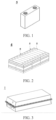
- FIG. 1 shows a prismatic secondary battery 5 as an example.
- the secondary battery according to this application may be assembled to form a battery module.
- the number of secondary batteries in a battery module may be plural, and may be adjusted according to practical applications and capacity of the battery module.
- FIG. 2 shows a battery module 4 as an example.
- a plurality of secondary batteries 5 may be arranged sequentially along a length direction of the battery module 4.
- the secondary batteries may be arranged in any other manner.
- the plurality of secondary batteries 5 may be fixed by a fastener.
- the battery module 4 may further include a housing that provides an accommodation space.
- the plurality of secondary batteries 5 are accommodated in the accommodation space.
- the battery module containing the secondary batteries may be assembled to form a battery pack.
- the number of the battery modules contained in a battery pack may be adjusted according to practical applications and the capacity of the battery pack.
- FIG. 3 and FIG. 4 show a battery pack 1 as an example.
- the battery pack 1 may include a battery box and a plurality of battery modules 4 disposed in the battery box.
- the battery box includes an upper box 2 and a lower box 3.
- the upper box 2 fits the lower box 3 to form a closed space for accommodating the battery modules 4.
- the plurality of battery modules 4 may be arranged in the battery box in any manner.
- the electrical device includes the secondary battery according to this application.
- the secondary battery is configured to provide a power supply for the electrical device.
- the electrical device may be, but without being limited to, a mobile device (such as a mobile phone or a laptop computer), an electric vehicle (such as a battery electric vehicle, a hybrid electric vehicle, a plug-in hybrid electric vehicle, an electric bicycle, an electric scooter, an electric golf cart, or an electric truck), an electric train, a ship, a satellite system, or an energy storage system.
- the secondary battery, the battery module, or the battery pack may be selected for use in the electrical device according to practical requirements of the electrical device.
- FIG. 5 shows an electrical device as an example.
- the electrical device may be a battery electric vehicle, a hybrid electric vehicle, a plug-in hybrid electric vehicle, or the like.
- the electrical device may adopt a battery pack or a battery module in order to meet the requirements of the electrical device on a high power and a high energy density of the secondary battery.
- the electrical device may be a mobile phone, a tablet computer, a notebook computer, or the like.
- the electrical device is generally required to be thin and light, and may employ a secondary battery as a power supply.
- LiNi 1/3 Mn 1/3 Co 1/3 O 2 as an active material
- acetylene black as a conductive agent
- PVDF polyvinylidene difluoride
- EC ethylene carbonate
- EMC ethyl methyl carbonate
- DEC diethyl carbonate
- the concentration of the LiPF 6 is 1 mol/L.
- the separator prepared in each embodiment or comparative embodiment is ready for use in a battery cell.
- Stacking the positive electrode plate, the separator, and the negative electrode plate sequentially, placing the separator between the positive electrode and the negative electrode to serve a function of separation, and winding the stacked structure to obtain a bare cell.
- the test process is as follows:
- the test process is as follows:
- Embodiment 2 Identical to Embodiment 1 except the mass ratio between the first organic particle and the pressure-sensitive binder polymer in the pressure-sensitive coating. Specifically, The mass ratio between the first organic particle and the pressure-sensitive binder polymer in the pressure-sensitive coating of the separator prepared in Embodiment 2 is 90: 10.
- the mass ratio between the first organic particle and the pressure-sensitive binder polymer in the pressure-sensitive coating of the separator prepared in Embodiment 3 is 80: 20.
- Embodiment 4 Identical to Embodiment 1 except the binder polymer or plasticizer in the pressure-sensitive binder polymer.
- the binder polymer in the pressure-sensitive binder polymer used in Embodiment 4 is: 30% isobutyl acrylate + 25% isooctyl acrylate + 5% 2-hydroxypropyl acrylate + 15% styrene + 22% acrylamide + 3% polyethylene glycol copolymer; and the plasticizer is glycerol.
- the binder polymer in the pressure-sensitive binder polymer used in Embodiment 5 is: 30% cyclohexyl acrylate + 25% tetrahydrofuryl methacrylate + 5% 2-hydroxypropyl methacrylate + 15% styrene + 22% acrylonitrile + 3% polyethylene glycol copolymer; and the plasticizer is glycerol.
- the binder polymer in the pressure-sensitive binder polymer used in Embodiment 6 is: 30% cyclohexyl acrylate + 25% tetrahydrofuryl methacrylate + 5% vinylstyrene + 15% styrene + 22% acrylonitrile + 3% polyethylene glycol copolymer; and the plasticizer is glycerol.
- the binder polymer in the pressure-sensitive binder polymer used in Embodiment 7 is: 30% isobutyl acrylate + 25% isooctyl acrylate + 5% vinylstyrene + 15% styrene + 22% acrylonitrile + 3% polyvinyl alcohol copolymer; and the plasticizer is glycerol.
- the binder polymer in the pressure-sensitive binder polymer used in Embodiment 8 is: 30% isobutyl acrylate + 25% isooctyl acrylate + 5% 2-hydroxypropyl methacrylate + 15% styrene + 22% acrylonitrile + 3% polyvinyl alcohol copolymer; and the plasticizer is C 4 to C 10 glycerol alkyl diether.
- the binder polymer in the pressure-sensitive binder polymer used in Embodiment 9 is: 30% isobutyl acrylate + 25% isooctyl acrylate + 5% 2-hydroxypropyl methacrylate + 15% styrene + 22% acrylonitrile + 3% polyvinyl alcohol copolymer; and the plasticizer is C 4 to C 10 propylene glycol alkyl monoether.
- Embodiment 10 Identical to Embodiment 1 except the graft rate of the plasticizer in the pressure-sensitive binder polymer. Specifically, The graft rate of the plasticizer in the pressure-sensitive binder polymer used in Embodiment 10 is 5 wt%.
- the graft rate of the plasticizer in the pressure-sensitive binder polymer used in Embodiment 11 is 3 wt%.
- the graft rate of the plasticizer in the pressure-sensitive binder polymer used in Embodiment 12 is 0 wt%, that is, no plasticizer is grafted.
- Embodiment 13 Identical to Embodiment 13 except the mass ratio between the organic particles and the pressure-sensitive binder polymer in the pressure-sensitive coating. Specifically,
- the mass ratio between the organic particles and the pressure-sensitive binder polymer in the pressure-sensitive coating of the separator prepared in Embodiment 14 is 85: 15, in which the mass ratio between the first organic particle and the second organic particle in the organic particles is 75: 10.
- the mass ratio between the organic particles and the pressure-sensitive binder polymer in the pressure-sensitive coating of the separator prepared in Embodiment 15 is 90: 10, in which the mass ratio between the first organic particle and the second organic particle in the organic particles is 65: 25.
- Embodiment 1 Identical to Embodiment 1 except the mass ratio between the first organic particle and the pressure-sensitive binder polymer in the pressure-sensitive coating. Specifically, The mass ratio between the first organic particle and the pressure-sensitive binder polymer in the pressure-sensitive coating of the separator prepared in Comparative Embodiment 1 is 91: 9.
- the mass ratio between the first organic particle and the pressure-sensitive binder polymer in the pressure-sensitive coating of the separator prepared in Comparative Embodiment 2 is 74: 26.
- Embodiment 3 Identical to Embodiment 1 except that the pressure-sensitive binder polymer described in Embodiment 1 is not used.
- the separator prepared in Comparative Embodiment 3 contains the binder polymer alone but contains no plasticizer, and the mass ratio between the first organic particle and the binder polymer in the pressure-sensitive coating of the prepared separator is 85: 15.
- the separator prepared in Comparative Embodiment 4 contains the plasticizer alone but contains no binder polymer, and the mass ratio between the first organic particle and the plasticizer in the pressure-sensitive coating of the prepared separator is 85: 15.
- the pressure-sensitive binder polymer prepared from the binder polymer and the plasticizer is used for preparing the separator, and organic particles are used together.
- the separator is effectively endowed with high bonding performance and high ion conductivity under normal temperature conditions.
- the resistance of all the prepared separators is below 1.32 ⁇ under normal temperature conditions.
- the bonding force between each of the separators and the positive electrode is at least 0.70 N/m or even at least 1.00 N/m, and the bonding force between each of the separators and the negative electrode is at least 0.50 N/m.
- the prepared separators can avoid the bonding between the layers of a separator during rewinding and storage.
- the electrode plate and the separator can be closely fitted under normal temperature conditions.
- the scrap of the battery cell, deterioration of the cell performance, and safety hazards are prevented from being caused by dislocation between the electrode plate and the separator.
- the tunnel furnace and the second lamination step in a conventional battery cell production process can be omitted, thereby saving production space and production time, reducing energy consumption, and significantly increasing the productivity of battery cells.
- the shaping performance, safety performance, and kinetic performance of the battery cells can be enhanced.
- the grafting of the plasticizer into the pressure-sensitive binder polymer reduces the resistance of the separator, and improves the cycle performance of the secondary battery prepared from the separator.
- the graft rate of the plasticizer in the pressure-sensitive binder polymer is at least 5 wt%, the resistance of the separator is lower, and the cycle performance of the secondary battery is higher.
- Embodiment 1 Identical to Embodiment 1 except the particle diameter of the first organic particle and the thickness of the pressure-sensitive coating.
- the particle diameter of the first organic particle used in Embodiment 16 is approximately 3 ⁇ m, and the thickness of the pressure-sensitive coating is approximately 0.8 ⁇ m.
- the particle diameter of the first organic particle used in Embodiment 17 is approximately 5 ⁇ m, and the thickness of the pressure-sensitive coating is approximately 2 ⁇ m.
- the particle diameter of the first organic particle used in Embodiment 18 is approximately 20 ⁇ m, and the thickness of the pressure-sensitive coating is approximately 15 ⁇ m.
- the particle diameter of the first organic particle used in Embodiment 19 is approximately 30 ⁇ m, and the thickness of the pressure-sensitive coating is approximately 20 ⁇ m.
- the particle diameter of the first organic particle used in Embodiment 20 is approximately 36 ⁇ m, and the thickness of the pressure-sensitive coating is approximately 22 ⁇ m.
- Embodiment 1 Identical to Embodiment 1 except the particle diameter of the pressure-sensitive binder polymer.
- the particle diameter of the pressure-sensitive binder polymer used in Embodiment 21 is approximately 0.3 ⁇ m.
- the particle diameter of the pressure-sensitive binder polymer used in Embodiment 22 is approximately 0.5 ⁇ m.
- the particle diameter of the pressure-sensitive binder polymer used in Embodiment 23 is approximately 0.8 ⁇ m.
- the particle diameter of the pressure-sensitive binder polymer used in Embodiment 24 is approximately 1.0 ⁇ m.
- the particle diameter of the pressure-sensitive binder polymer used in Embodiment 25 is approximately 2.0 ⁇ m.
- the particle diameter of the pressure-sensitive binder polymer used in Embodiment 26 is approximately 3.0 ⁇ m.
- the particle diameter of the pressure-sensitive binder polymer used in Embodiment 27 is approximately 3.5 ⁇ m.
- Embodiment 1 Identical to Embodiment 1 except the mass ratio between the binder polymer and the plasticizer in the pressure-sensitive binder polymer.
- the mass ratio between the binder polymer and the plasticizer in the pressure-sensitive binder polymer used in Embodiment 28 is approximately 3: 1.
- the mass ratio between the binder polymer and the plasticizer in the pressure-sensitive binder polymer used in Embodiment 29 is approximately 4: 1.
- the mass ratio between the binder polymer and the plasticizer in the pressure-sensitive binder polymer used in Embodiment 30 is approximately 11: 1.
- the mass ratio between the binder polymer and the plasticizer in the pressure-sensitive binder polymer used in Embodiment 31 is approximately 19: 1.
- the mass ratio between the binder polymer and the plasticizer in the pressure-sensitive binder polymer used in Embodiment 32 is approximately 21: 1.
- Embodiment 14 Identical to Embodiment 14 except the particle diameter of the second organic particle and the thickness of the prepared pressure-sensitive coating.
- the particle diameter of the second organic particle used in Embodiment 33 is approximately 0.3 ⁇ m, and the thickness of the pressure-sensitive coating is approximately 3 ⁇ m.
- the particle diameter of the second organic particle used in Embodiment 34 is approximately 0.5 ⁇ m, and the thickness of the pressure-sensitive coating is approximately 3 ⁇ m.
- the particle diameter of the second organic particle used in Embodiment 35 is approximately 2 ⁇ m, and the thickness of the pressure-sensitive coating is approximately 3 ⁇ m.
- the particle diameter of the second organic particle used in Embodiment 36 is approximately 8 ⁇ m, and the thickness of the pressure-sensitive coating is approximately 4 ⁇ m.
- the particle diameter of the second organic particle used in Embodiment 37 is approximately 10 ⁇ m, and the thickness of the pressure-sensitive coating is approximately 6 ⁇ m.
- the particle diameter of the second organic particle used in Embodiment 38 is approximately 12 ⁇ m, and the thickness of the pressure-sensitive coating is approximately 10 ⁇ m.
- Embodiments 16 to 20 the particle diameter of the first organic particle is changed; in Embodiments 21 to 27, the particle diameter of the pressure-sensitive binder polymer is changed; in Embodiments 28 to 32, the mass ratio between the binder polymer and the plasticizer included in the pressure-sensitive binder polymer is changed; and, in Embodiments 33 to 38, the particle diameter of the second organic particle is changed.
- the particle diameter of the second organic particle is changed.
- the bonding force between each of the separators and the positive electrode is at least 0.56 N/m under a pressure greater than or equal to 2 MPa; and the bonding force between each of the separators and the electrode is below 0.23 N/m under a pressure less than or equal to 1 MPa.
- the secondary batteries prepared from the separators made in such embodiments also exhibit good cycle performance, and the capacity retention rates of all the batteries under 25 °C and 45 °C conditions are at least 70%.
- the separators are more effectively endowed with high bonding performance and ion-conductivity under normal temperature conditions, the resistance of all the separators is below 1.1 ⁇ under normal temperature conditions.
- the bonding force between each of the separators and the positive electrode is at least 0.80 N/m under a pressure greater than or equal to 2 MPa, and the bonding force between each of the separators and the electrode is below 0.1 N/m under a pressure less than or equal to 1 MPa.
- the secondary batteries prepared from the separators made also exhibit higher cycle performance, and the capacity retention rates of all the batteries are at least 80 % under 25 °C and 45 °C conditions.
- the pressure-sensitive binder polymer in use is a core-shell structured pressure-sensitive binder polymer.
- Both the core and the shell of the pressure-sensitive binder polymer of the core-shell structured pressure-sensitive binder polymer include a binder polymer and a plasticizer.
- Table 3 shows the mass ratio between the binder polymer and the plasticizer in the core and shell of the pressure-sensitive binder polymer used in Embodiments 39 to 47.
- the separator is more effectively endowed with high bonding performance and high ion conductivity under normal temperature conditions.
- the resistance of all the prepared separators is lower than 0.9 ⁇ .
- the bonding force between each of the separators and the positive electrode is at least 1.21 N/m
- the bonding force between each of the separators and the negative electrode is at least 0.85 N/m.
- the bonding force between each of the separators and the electrode is below 0.1 N/m.
- All the prepared secondary batteries exhibit good cycle performance, and the capacity retention rates of the batteries are higher than 89% under 25 °C and 45°C conditions.
- the mass ratio between the binder polymer and the plasticizer in the core of the core-shell structured pressure-sensitive binder polymer falls within (3 to 4): 1
- the mass ratio between the binder polymer and the plasticizer in the shell falls within (7 to 9): 1
- the separators are more effectively endowed with high bonding performance and ion-conductivity under normal temperature conditions, the resistance of the prepared separators is even lower than 0.8 ⁇ .
- the bonding force between each of the separators and the positive electrode is at least 1.23 N/m and the bonding force between each of the separators and the negative electrode is at least 1.1 N/m.
- the bonding force between all the separators and the electrode is below 0.1 N/m.
- the secondary batteries prepared from the separators made also exhibit higher cycle performance, and the capacity retention rates of all the batteries are at least 91% under 25 °C and 45 °C conditions.
Landscapes
- Chemical & Material Sciences (AREA)
- Chemical Kinetics & Catalysis (AREA)
- Electrochemistry (AREA)
- General Chemical & Material Sciences (AREA)
- Engineering & Computer Science (AREA)
- Manufacturing & Machinery (AREA)
- Materials Engineering (AREA)
- Inorganic Chemistry (AREA)
- Cell Separators (AREA)
Applications Claiming Priority (1)
| Application Number | Priority Date | Filing Date | Title |
|---|---|---|---|
| PCT/CN2021/143069 WO2023123205A1 (zh) | 2021-12-30 | 2021-12-30 | 隔离膜及其制备方法以及包含该隔离膜的二次电池和用电装置 |
Publications (2)
| Publication Number | Publication Date |
|---|---|
| EP4239780A1 true EP4239780A1 (de) | 2023-09-06 |
| EP4239780A4 EP4239780A4 (de) | 2024-12-25 |
Family
ID=86996992
Family Applications (1)
| Application Number | Title | Priority Date | Filing Date |
|---|---|---|---|
| EP21964985.2A Pending EP4239780A4 (de) | 2021-12-30 | 2021-12-30 | Separator und herstellungsverfahren dafür, sekundärbatterie mit dem separator und elektrische vorrichtung |
Country Status (4)
| Country | Link |
|---|---|
| US (1) | US20230307786A1 (de) |
| EP (1) | EP4239780A4 (de) |
| CN (1) | CN117063343A (de) |
| WO (1) | WO2023123205A1 (de) |
Families Citing this family (9)
| Publication number | Priority date | Publication date | Assignee | Title |
|---|---|---|---|---|
| CN116706436B (zh) * | 2023-08-04 | 2023-11-07 | 宁德时代新能源科技股份有限公司 | 隔离膜及其制备方法、二次电池和用电装置 |
| CN116742278B (zh) * | 2023-08-14 | 2023-10-24 | 中材锂膜(宜宾)有限公司 | 隔离膜及其制备方法、应用该隔离膜的电化学电池、用电装置 |
| CN117253652B (zh) * | 2023-11-16 | 2024-04-16 | 宁德时代新能源科技股份有限公司 | 绝缘胶液及制备方法、绝缘胶膜、正极极片、二次电池及用电装置 |
| CN120271942A (zh) * | 2024-01-05 | 2025-07-08 | 宁德时代新能源科技股份有限公司 | 复合材料及其制备方法、隔离膜、极片、电池及用电装置 |
| CN120280659A (zh) * | 2024-01-05 | 2025-07-08 | 宁德时代新能源科技股份有限公司 | 隔离膜及其制备方法、电池、用电装置 |
| CN120424597A (zh) * | 2024-02-02 | 2025-08-05 | 宁德时代新能源科技股份有限公司 | 聚合物、隔离膜、电池、用电装置 |
| WO2025213173A1 (en) * | 2024-04-05 | 2025-10-09 | Enevate Corporation | Safety-enhancement state-of-charge reduction devices for propagation resistant lithium-ion batteries |
| CN118336293B (zh) * | 2024-05-11 | 2024-12-10 | 广州埃登达化工有限公司 | 一种锂电池隔膜 |
| CN119581787A (zh) * | 2024-12-02 | 2025-03-07 | 江苏正力新能电池技术股份有限公司 | 隔膜及其制备方法和电池 |
Family Cites Families (6)
| Publication number | Priority date | Publication date | Assignee | Title |
|---|---|---|---|---|
| GB0211164D0 (en) * | 2002-05-16 | 2002-06-26 | Accentus Plc | Electrochemical cell assembly |
| CN103441230B (zh) * | 2013-08-21 | 2016-03-09 | 东莞新能源科技有限公司 | 有机/无机复合多孔隔离膜及其制备方法及电化学装置 |
| CN103956450B (zh) * | 2014-05-16 | 2016-08-24 | 中国东方电气集团有限公司 | 一种锂离子电池用复合隔膜及其制备方法 |
| CN110137414B (zh) * | 2018-02-09 | 2021-06-01 | 北京师范大学 | 一种包括片层结构的pvdf涂层的复合隔膜及其制备方法和用途 |
| CN109742290A (zh) * | 2018-12-13 | 2019-05-10 | 中航锂电(洛阳)有限公司 | 一种压敏耐高温型功能隔膜、压敏耐高温颗粒及制备方法 |
| CN113224466B (zh) * | 2020-01-19 | 2023-06-16 | 厦门大学 | 一种压敏高分子改性隔膜及其制备方法和应用 |
-
2021
- 2021-12-30 CN CN202180096158.1A patent/CN117063343A/zh active Pending
- 2021-12-30 EP EP21964985.2A patent/EP4239780A4/de active Pending
- 2021-12-30 WO PCT/CN2021/143069 patent/WO2023123205A1/zh not_active Ceased
-
2023
- 2023-06-01 US US18/327,269 patent/US20230307786A1/en active Pending
Also Published As
| Publication number | Publication date |
|---|---|
| CN117063343A (zh) | 2023-11-14 |
| US20230307786A1 (en) | 2023-09-28 |
| WO2023123205A1 (zh) | 2023-07-06 |
| EP4239780A4 (de) | 2024-12-25 |
Similar Documents
| Publication | Publication Date | Title |
|---|---|---|
| US20230307786A1 (en) | Separator, preparation method of same, secondary battery containing same, and electrical device | |
| KR101236453B1 (ko) | 실리콘 음극, 리튬 이온 배터리 및 이의 제조 방법 | |
| US20240079727A1 (en) | Separator, electrochemical apparatus comprising the same, and electronic device | |
| US20240145762A1 (en) | Lithium-ion battery | |
| JP7446459B2 (ja) | セパレータ、その製造方法およびそれに関連する二次電池、電池モジュール、電池パックならびに装置 | |
| JP7590414B2 (ja) | 二次電池、二次電池を含む装置、二次電池の製造方法及び接着剤組成物 | |
| US20240145868A1 (en) | Separator, preparation method thereof, and secondary battery, battery module, battery pack, and electric apparatus | |
| US20240274978A1 (en) | Separator and preparation method thereof, battery, and electric apparatus | |
| US20240047643A1 (en) | Negative pressure formation method for lithium iron manganese phosphate batteries and batteries applying the same | |
| WO2023179333A1 (zh) | 隔离膜及其制备方法、电池和用电装置 | |
| WO2022141508A1 (zh) | 一种电化学装置和电子装置 | |
| US20240204305A1 (en) | Secondary battery and electronic apparatus | |
| CN111600033B (zh) | 一种负极粘结剂及其应用 | |
| KR102846665B1 (ko) | 음극의 제조방법 | |
| US20250015272A1 (en) | Secondary battery and electronic device | |
| EP4503193A1 (de) | Elektrochemische vorrichtung und elektronische vorrichtung damit | |
| KR101616721B1 (ko) | 접착력이 향상된 바인더 및 상기 바인더를 포함하는 리튬 이차전지 | |
| CN115548424B (zh) | 一种电化学装置和电子装置 | |
| JP7645033B2 (ja) | スチレンアクリルエマルジョン及びその製造方法、負極シート、二次電池並びに電力消費装置 | |
| US20250015400A1 (en) | Expansion tape for battery packaging, preparation method and application thereof, secondary battery, and electric apparatus | |
| WO2025146169A1 (zh) | 隔离膜及其制备方法、电池、用电装置 | |
| CN119133585A (zh) | 凝胶聚合物电解质及其制备方法、锂金属电池以及电子产品 | |
| HK1162755A (en) | Liquid-state soft package lithium battery and preparation method thereof |
Legal Events
| Date | Code | Title | Description |
|---|---|---|---|
| STAA | Information on the status of an ep patent application or granted ep patent |
Free format text: STATUS: UNKNOWN |
|
| STAA | Information on the status of an ep patent application or granted ep patent |
Free format text: STATUS: THE INTERNATIONAL PUBLICATION HAS BEEN MADE |
|
| PUAI | Public reference made under article 153(3) epc to a published international application that has entered the european phase |
Free format text: ORIGINAL CODE: 0009012 |
|
| STAA | Information on the status of an ep patent application or granted ep patent |
Free format text: STATUS: REQUEST FOR EXAMINATION WAS MADE |
|
| 17P | Request for examination filed |
Effective date: 20230602 |
|
| AK | Designated contracting states |
Kind code of ref document: A1 Designated state(s): AL AT BE BG CH CY CZ DE DK EE ES FI FR GB GR HR HU IE IS IT LI LT LU LV MC MK MT NL NO PL PT RO RS SE SI SK SM TR |
|
| RAP1 | Party data changed (applicant data changed or rights of an application transferred) |
Owner name: CONTEMPORARY AMPEREX TECHNOLOGY(HONG KONG) LIMITED |
|
| A4 | Supplementary search report drawn up and despatched |
Effective date: 20241122 |
|
| RIC1 | Information provided on ipc code assigned before grant |
Ipc: H01M 50/443 20210101ALI20241118BHEP Ipc: H01M 50/403 20210101ALI20241118BHEP Ipc: H01M 10/0525 20100101ALI20241118BHEP Ipc: H01M 50/411 20210101ALI20241118BHEP Ipc: H01M 50/449 20210101AFI20241118BHEP |
|
| DAV | Request for validation of the european patent (deleted) | ||
| DAX | Request for extension of the european patent (deleted) |