EP4239772A1 - Gehäusekörperanordnung, batterie, elektrische vorrichtung und verfahren und vorrichtung zur herstellung der gehäusekörperanordnung - Google Patents
Gehäusekörperanordnung, batterie, elektrische vorrichtung und verfahren und vorrichtung zur herstellung der gehäusekörperanordnung Download PDFInfo
- Publication number
- EP4239772A1 EP4239772A1 EP21948027.4A EP21948027A EP4239772A1 EP 4239772 A1 EP4239772 A1 EP 4239772A1 EP 21948027 A EP21948027 A EP 21948027A EP 4239772 A1 EP4239772 A1 EP 4239772A1
- Authority
- EP
- European Patent Office
- Prior art keywords
- channel
- inserting portion
- end plate
- partition
- box assembly
- Prior art date
- Legal status (The legal status is an assumption and is not a legal conclusion. Google has not performed a legal analysis and makes no representation as to the accuracy of the status listed.)
- Pending
Links
Images


Classifications
-
- H—ELECTRICITY
- H01—ELECTRIC ELEMENTS
- H01M—PROCESSES OR MEANS, e.g. BATTERIES, FOR THE DIRECT CONVERSION OF CHEMICAL ENERGY INTO ELECTRICAL ENERGY
- H01M50/00—Constructional details or processes of manufacture of the non-active parts of electrochemical cells other than fuel cells, e.g. hybrid cells
- H01M50/20—Mountings; Secondary casings or frames; Racks, modules or packs; Suspension devices; Shock absorbers; Transport or carrying devices; Holders
- H01M50/289—Mountings; Secondary casings or frames; Racks, modules or packs; Suspension devices; Shock absorbers; Transport or carrying devices; Holders characterised by spacing elements or positioning means within frames, racks or packs
-
- H—ELECTRICITY
- H01—ELECTRIC ELEMENTS
- H01M—PROCESSES OR MEANS, e.g. BATTERIES, FOR THE DIRECT CONVERSION OF CHEMICAL ENERGY INTO ELECTRICAL ENERGY
- H01M50/00—Constructional details or processes of manufacture of the non-active parts of electrochemical cells other than fuel cells, e.g. hybrid cells
- H01M50/20—Mountings; Secondary casings or frames; Racks, modules or packs; Suspension devices; Shock absorbers; Transport or carrying devices; Holders
- H01M50/204—Racks, modules or packs for multiple batteries or multiple cells
-
- H—ELECTRICITY
- H01—ELECTRIC ELEMENTS
- H01M—PROCESSES OR MEANS, e.g. BATTERIES, FOR THE DIRECT CONVERSION OF CHEMICAL ENERGY INTO ELECTRICAL ENERGY
- H01M50/00—Constructional details or processes of manufacture of the non-active parts of electrochemical cells other than fuel cells, e.g. hybrid cells
- H01M50/20—Mountings; Secondary casings or frames; Racks, modules or packs; Suspension devices; Shock absorbers; Transport or carrying devices; Holders
- H01M50/233—Mountings; Secondary casings or frames; Racks, modules or packs; Suspension devices; Shock absorbers; Transport or carrying devices; Holders characterised by physical properties of casings or racks, e.g. dimensions
- H01M50/242—Mountings; Secondary casings or frames; Racks, modules or packs; Suspension devices; Shock absorbers; Transport or carrying devices; Holders characterised by physical properties of casings or racks, e.g. dimensions adapted for protecting batteries against vibrations, collision impact or swelling
-
- H—ELECTRICITY
- H01—ELECTRIC ELEMENTS
- H01M—PROCESSES OR MEANS, e.g. BATTERIES, FOR THE DIRECT CONVERSION OF CHEMICAL ENERGY INTO ELECTRICAL ENERGY
- H01M50/00—Constructional details or processes of manufacture of the non-active parts of electrochemical cells other than fuel cells, e.g. hybrid cells
- H01M50/20—Mountings; Secondary casings or frames; Racks, modules or packs; Suspension devices; Shock absorbers; Transport or carrying devices; Holders
- H01M50/244—Secondary casings; Racks; Suspension devices; Carrying devices; Holders characterised by their mounting method
-
- H—ELECTRICITY
- H01—ELECTRIC ELEMENTS
- H01M—PROCESSES OR MEANS, e.g. BATTERIES, FOR THE DIRECT CONVERSION OF CHEMICAL ENERGY INTO ELECTRICAL ENERGY
- H01M2220/00—Batteries for particular applications
- H01M2220/20—Batteries in motive systems, e.g. vehicle, ship, plane
-
- Y—GENERAL TAGGING OF NEW TECHNOLOGICAL DEVELOPMENTS; GENERAL TAGGING OF CROSS-SECTIONAL TECHNOLOGIES SPANNING OVER SEVERAL SECTIONS OF THE IPC; TECHNICAL SUBJECTS COVERED BY FORMER USPC CROSS-REFERENCE ART COLLECTIONS [XRACs] AND DIGESTS
- Y02—TECHNOLOGIES OR APPLICATIONS FOR MITIGATION OR ADAPTATION AGAINST CLIMATE CHANGE
- Y02E—REDUCTION OF GREENHOUSE GAS [GHG] EMISSIONS, RELATED TO ENERGY GENERATION, TRANSMISSION OR DISTRIBUTION
- Y02E60/00—Enabling technologies; Technologies with a potential or indirect contribution to GHG emissions mitigation
- Y02E60/10—Energy storage using batteries
Definitions
- Embodiments of this application are implemented as follows.
- the bending region is provided in the inserting portion, so that when the end plate is extruded, the bending region stretches and deforms to disperse stress, so as to alleviate deformation and damage due to stress on the joint, thereby further improving the safety and service life of the battery.
- the at least two channels include a first channel and a second channel, where an inner wall of the first channel includes a first surface, the first surface faces toward a first direction, an inner wall of the second channel includes a second surface, the second surface facing toward a second direction, and the first direction is opposite to the second direction; and the at least two inserting portions include a first inserting portion and a second inserting portion, where the first inserting portion is configured to fit with the first channel by inserting, and the first inserting portion abuts against the first surface; and the second inserting portion is configured to fit with the second channel, and the second inserting portion abuts against the second surface.
- the first inserting portion and the second inserting portion respectively abut against two surfaces facing opposite directions, so that the first inserting portion and the second inserting portion restrain each other, and the first inserting portion and the second inserting portion clamp the end plate or are clamped by a first surface and a second surface on the end plate, so as to implement positioning of the partition.
- the first direction and the second direction are parallel to a width direction of the end plate.
- the first inserting portion and the second inserting portion are clamped along the width direction of the end plate, and both the first surface and the second surface are parallel to the partition. This helps improve positioning accuracy of the partition in the width direction of the end plate, and further ensuring that the partition accurately separates the internal space of the box assembly.
- the first channel and the second channel being arranged in the height direction of the end plate allows the partition to have an abutting position at an upper section and a lower section respectively, which prevents the partition from titling toward a side in its thickness direction, ensuring stable connection and accurate positioning of the partition.
- projections of the first surface and the second surface on a bottom surface of the end plate in the height direction of the end plate overlap.
- the inner wall of the first channel further includes a third surface opposite the first surface, and a first clearance is present between the first inserting portion and the third surface; and the inner wall of the second channel further includes a fourth surface opposite the second surface, and a second clearance is present between the second inserting portion and the fourth surface.
- Clearance fit between the channel and its corresponding inserting portion facilitates entering of the inserting portion into the channel, avoiding a problem that the inserting portion cannot insert into the channel due to a manufacturing tolerance.
- the inserting portion With disposition of the guide slope, the inserting portion enters its corresponding channel through guidance of the guide slope, preventing an end portion of the inserting portion colliding with a location near the channel, and facilitating entering of the inserting portion into the channel.
- the first inserting portion and the second inserting portion are spaced apart along a height direction of the partition.
- the two inserting portions are arranged along the height direction of the partition so that the two inserting portions can be manufactured into larger ones, which makes them easy to manufacture and have higher structural strength.
- two restraining forces are imposed in the height direction of the partition, preventing an upper end or a lower end of the partition from tilting toward the thickness direction of the partition.
- each of the inserting portions and the inner wall of the fitting channel are connected at an abutting position to form a connecting seam; and the inserting portion and the partition are welded to each other at the connecting seam.
- the inserting portion and the inner wall of the channel abut against each other, with a small clearance formed at the abutting position, which is conducive to fastening by bonding, welding, or the like.
- the partition is further positioned by welding at the abutting position.
- the bending region shields the connecting seam, when the connecting seam is formed at the abutting position by welding, the bending region functions as a light block. This prevents the welding laser from getting inside the box and irradiating the battery cell, avoiding damage of a housing of the battery cell, and preventing a cell blue membrane inside the battery cell from being burnt due to overheating of the housing of the battery cell.
- the inserting portion inserting into the channel can flexibly abut against an inner wall of the channel.
- the connecting region shifts relative to the body, and the bending region is configured as a step, flexibility of the inserting portion in a width direction increases, and force applied onto the inner wall of the channel against which the inserting portion abuts increases. Therefore, a restraining force formed by two or more inserting portions increases, allowing more stable clamping and improved positioning effect.
- the step formed by the bending region can also be stretched to release swelling force.
- each of the connecting regions and each of the bending regions are equal in thickness to the body.
- Thicknesses of the body, the connecting regions connected to the body, and the bending region are set to be equal to prevent a thin part from being damaged first, ensuring integrity of the partition and avoiding influence on the service life of the battery due to damage of the partition.
- two projections of the at least two channels on the bottom surface of the end plate in the height direction of the end plate partially overlap or are spaced apart, or the two projections are arranged as connected in edge.
- the connecting groove allows a weak region to be formed in the first channel and the second channel, so as to disperse stress and prevent damage at a joint.
- an embodiment of this application provides a battery, including the foregoing box assembly.
- the foregoing box assembly is used to accommodate a battery cell, where positioning of a partition in the box assembly is accurate and stable, and an internal space of the box assembly is separated with high accuracy, so that service life of the battery is not likely to be reduced due to extrusion on the battery cell.
- an embodiment of this application provides an electric device, including the foregoing battery.
- the electric device provided in this application employs the foregoing battery, and therefore has stable power supply and good durability.
- an embodiment of this application provides a manufacturing method of box assembly, including: providing an end plate, where the end plate is provided with at least two channels; providing a partition, where the partition is configured to be connected to the end plate and separate an internal space of the box assembly; the partition includes a body and at least two inserting portions located on an end of the body, each of the inserting portions including a connecting region and a bending region, with the connecting region connected to the body through the bending region; and each channel of the at least two channels fits with the at least one inserting portion by inserting, so that the connecting region of each of the inserting portions abuts against an inner wall of a fitting channel, allowing the partition to be connected to the end plate; and inserting the inserting portion into the channel.
- an embodiment of this application provides a manufacturing apparatus of box assembly, including: a first providing apparatus, configured to provide an end plate, where the end plate is provided with at least two channels; a second providing apparatus, configured to provide a partition, where the partition is configured to be connected to the end plate and separate an internal space of the box assembly; the partition includes a body and at least two inserting portions located on one end of the body, each of the inserting portions including a connecting region and a bending region, with the connecting region connected to the body through the bending region; and each channel of the at least two channels fits with the at least one inserting portion by inserting, so that the connecting region of each of the inserting portions abuts against an inner wall of a fitting channel, allowing the partition to be connected to the end plate; and an assembly apparatus, configured to insert the inserting portion into the channel.
- connection should be understood in its general sense.
- the "connect” may refer to a fixed connection, a detachable connection, or an integral connection; and the “connect” may refer to a direct connection or an indirect connection via an intermediate medium. Persons skilled in the art can understand specific meanings of these terms in this application as appropriate to specific situations.
- the battery cell may include a lithium-ion secondary battery, a lithium-ion primary battery, a lithium-sulfur battery, a sodium-lithium-ion battery, a sodium-ion battery, a magnesium-ion battery, or the like. This is not limited in the embodiments of this application.
- the battery cell may be cylindrical, flat, cuboid, or of other shapes, which is not limited in the embodiments of this application either. Battery cells are typically divided into three types by packaging method: cylindrical cell, prismatic cell, and pouch cell. The type of battery is not limited in the embodiments of this application either.
- the battery mentioned in the embodiments of this application is a single physical module that includes multiple battery cells for providing higher voltage and capacity.
- the battery mentioned in this application may include a battery module, a battery pack, or the like.
- a manner adopted in the prior art is as follows: A channel is provided on the partition, an inserting portion is provided on an end of the partition, and the inserting portion inserts into the channel and welded to the channel, so as to implement connection and positioning of the partition.
- the inserting portion In the prior manner, in order to alleviate a problem of unsmooth insertion of the inserting portion into the channel caused by a manufacturing tolerance, the inserting portion generally needs to be thinned to have a size smaller than the channel, to ensure that the inserting portion can insert into the channel smoothly.
- the prior manner brings other problems. For example, to ensure accurate positioning of the partition, the inserting portion needs to be welded to an inner wall of the channel.
- the inserting portion has a smaller size than the channel, the inserting portion is movable in the channel, and the inserting portion is hard to be positioned, which leads to deviation of a welding position, and finally leads to inaccurate positioning of the partition, affecting service life of the battery.
- this application provides a technical solution so as to improve positioning accuracy of a partition.
- At least two inserting portions are provided at an end of a partition of a box assembly, an end plate that is configured to be connected to the partition is provided with at least two channels, and each channel fits with at least one inserting portion, so that each inserting portion abuts against an inner wall of a fitting channel, so as to connect the partition to the end plate.
- the at least two inserting portions on the partition both abut against the inner wall of the fitting channel, allowing the at least two inserting portions to restrain each other.
- the at least two inserting portions fit to clamp the end plate, or a clamping force is applied by the at least two channels of the end plate, so that each inserting portion clings to the inner wall of the channel in which the inserting portion is located, and positioning of each inserting portion is implemented, thereby ensuring accurate positioning of the partition.
- the technical solutions described in the embodiments of this application are applicable to electric devices using a battery, and the electric device may be a ship, a vehicle, a drone, or the like.
- the vehicle is a new energy vehicle, which may be a battery electric vehicle, or may be a hybrid electric vehicle or a range-extended vehicle.
- a vehicle body is provided with a drive motor.
- the drive motor is electrically connected to the battery as a power source, and is provided with electrical energy by the battery.
- the drive motor is connected to wheels on the vehicle body through a transmission mechanism to drive the vehicle.
- the battery may also be used in an energy storage cabinet to provide electric power as a power source.
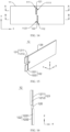
- FIG. 1 is a schematic structural diagram of an electric device according to an embodiment of this application.
- the electric device is a vehicle 1000, and the vehicle 1000 may be a fossil fuel vehicle, a natural-gas vehicle, or a new energy vehicle, where the new energy vehicle may be a battery electric vehicle, a hybrid electric vehicle, a range-extended vehicle, or the like.
- the vehicle 1000 is provided with a battery 100 inside.
- the battery 100 may be disposed at the bottom, front, or rear of the vehicle 1000.
- the battery 100 may be configured to supply power to the vehicle 1000.
- the battery 100 may be used as an operational power source for the vehicle 1000 which is configured for a circuit system of the vehicle 1000, for example, to satisfy power needs of start, navigation, and running of the vehicle 1000.
- the battery 100 can be used not only as the operational power source for the vehicle 1000, but also as a driving power source for the vehicle 1000, replacing or partially replacing fossil fuel or natural gas to provide driving traction for the vehicle 1000.
- the vehicle 1000 may further be provided with a controller 300 and a motor 200 inside, where the controller 300 is configured to control the battery 100 to supply power to the motor 200, for example, to satisfy power needs of start, navigation, and driving of the vehicle 1000.
- the controller 300 is configured to control the battery 100 to supply power to the motor 200, for example, to satisfy power needs of start, navigation, and driving of the vehicle 1000.
- the battery 100 may include a plurality of battery cells 2, where the plurality of battery cells 2 may be connected in series, parallel, or series-parallel, and being connected in series-parallel refers to a combination of series-parallel connections.
- the plurality of battery cells 2 may be connected in series, parallel, or series-parallel to form a battery module first, and then a plurality of battery modules are connected in series, parallel, or series-parallel to form the battery 100.
- the plurality of battery cells 2 may be directly combined into the battery 100, or may first be combined into battery modules which are then combined into the battery 100.
- the battery 100 may include a plurality of battery cells 2 and a box assembly 1.
- the box assembly 1 forms a space for accommodating the plurality of battery cells 2, so that the plurality of battery cells 2 are arranged in the space of the box assembly 1.
- the box assembly 1 is not limited to any specific type, and may be a frame-shaped box, a disk-shaped box, a box-shaped box, or the like.
- the box assembly 1 may include an upper box body and a lower box body, where the upper box body and the lower box body are snap-fitted together.
- the upper box body and the lower box body may each have an opening.
- the upper box body and the lower box body each may be a hollow cuboid and have only one surface with an opening, the opening of the upper box body is disposed opposite the opening of the lower box body, and the upper box body and the lower box body are snap-fitted to form the box assembly 1 with an accommodating space.
- one of the upper box body and the lower box body may be a cuboid with an opening, and the other of the upper box body and the lower box body may be a cover plate structure to close the opening of the cuboid.
- the plurality of battery cells 2 are connected in parallel, series, or parallel-series, and then placed into the box assembly 1 formed after the upper box body and the lower boxy body are snap-fitted.
- the upper box body of the box assembly 1 being a cover plate structure (not shown in the figure) and the lower box body being a cuboid with an opening are used as an example.
- the accommodating space of the box assembly 1 is located in the lower box body, and the upper box body covers the lower box body to close the accommodating space.
- the box assembly 1 includes an end plate 11 and a partition 12.
- a direction x, a direction y, and a direction z are defined according to a placement manner of the battery 100 in normal use, where the three directions are perpendicular to each other.
- a width direction of the end plate 11 is parallel to the direction x, a thickness direction of the end plate 11 is parallel to the direction y, and a height direction of the end plate 11 is parallel to the direction z; and a thickness direction of the partition 12 is parallel to the direction x, a width direction of the partition 12 is parallel to the direction y, and a height direction of the partition 12 is parallel to the direction z.
- the width direction of the end plate 11 refers to a direction along a longer side of the end plate 11
- the width direction of the partition 12 refers to a direction along a longer side of the partition 12.
- a plurality of battery cells 2 are respectively arranged in sequence on two sides of the partition 12 in the thickness direction. In other words, a plurality of battery cells 2 are arranged on one side of the partition 12 in the width direction of the partition 12, and a plurality of battery cells 2 are also arranged on the other side of the partition 12 in the width direction of the partition 12.
- the box assembly 1 may further include a side plate 13.
- the side plate 13 connects end portions of two end plates 11 in the width direction, where ends of the two end plates 11 are connected by a side plate 13 and other ends of the two end plates 11 are connected by another side plate 13.
- the box assembly 1 further includes a base plate 14.
- the base plate 14 is perpendicular to the end plate 11, the partition 12, and the side plate 13, that is, in a direction perpendicular to the direction z, the end plate 11, the partition 12, and the side plate 13 are all connected to the base plate 14, so that the accommodating space with one end open and the other end closed is formed in the box assembly 1.
- the battery 100 is placed into the accommodating space through the opening.
- the base plate 14 does not close the other end of the accommodating space.
- the base plate 14 is provided in a quantity of two, and each of the two base plates 14 is connected to one side plate 13 and extends from the side plate 13 in a direction approaching the partition plate 12, so that the other end of the accommodating space is locally shielded.
- the base plate 14 is a strip edge formed on the side plate 13, and the base plate 14 shields the battery cell 2, preventing the battery cell 2 from falling off the other end after entering the accommodating space through the opening.
- the base plate 14 may be eliminated, and two opposite surfaces of the battery cell 2 are clamped through coordination between the partition 12 and the side plate 13.
- the end plate 11, the side plate 13, and the base plate 14 may be integrally formed, or separately manufactured before connected as a whole.
- the end plate 11 is provided with at least two channels
- the partition 12 is provided with at least two inserting portions, where each channel fits with at least one inserting portion. In this way, each inserting portion abuts against an inner wall of a fitting channel, to implement positioning of each inserting portion, which makes the at least two inserting portions restrain each other, so as to connect the partition 12 to the end plate 11, ensuring accurate positioning of the partition 12.
- the channels are provided in a quantity of two or more, and the inserting portions are provided in a quantity of two or more.
- two channels are provided, and two inserting portions are provided, where the two inserting portions are respectively inserted into the two channels, and the two inserting portions respectively abut against the inner walls of the channels in which the two inserting portions are located.
- One inserting portion cannot move in one direction by abutting against the inner wall of the channel in which it is located, and the other inserting portion cannot move in another direction by abutting against the inner wall of the channel in which it is located, so that the two inserting portions restrain each other, and the partition cannot move, implementing positioning of the partition.
- two channels are provided, more than two inserting portions are provided, where each channel is inserted with at least one inserting portion. In some embodiments, two inserting portions are provided, more than two channels are provided, where each channel is inserted with at least one inserting portion.
- end plate 11 being provided with two channels and the partition 12 being provided with two inserting portions are used as an example for description.
- the at least two channels include a first channel 111 and a second channel 112, and the at least two inserting portions include a first inserting portion 121 and a second inserting portion 122.
- the first inserting portion 121 is configured to fit with the first channel 111
- the second inserting portion 122 is configured to fit with the second channel 112.
- An inner wall of the first channel 111 includes a first surface 1111, and the first inserting portion 121 abuts against the first surface 1111.
- An inner wall of the second channel 112 includes a second surface 1121, and the second inserting portion 122 abuts against the second surface 1121.
- a surface of the first inserting portion 121 facing toward the second direction abuts against the first surface 1111, and the first inserting portion 121 fits with the first surface 1111 to restrict moving of the partition 12 toward the second direction.
- a surface of the second inserting portion 122 facing toward the first direction abuts against the second surface 1121, and the second inserting portion 122 fits with the second surface 1121 to restrict moving of the partition 12 toward the first direction. In this way, the two inserting portions restrain each other, implementing positioning of the partition 12.
- the first channel 111 and the second channel 112 are arranged in multiple of manners, and two projections of the first channel 111 and the second channel 112 on a bottom surface of the end plate 11 in the height direction of the end plate 11 (namely, direction z) have a variety of cases, for example, fully overlapping, partially overlapping, being spaced apart, or arranged as connected in edge. It should be noted that, in a case that more than two channels are provided, two projections of the at least two channels, in the height direction of the end plate 11, on the bottom surface of the end plate 11 may fully overlap, partially overlap, or be spaced apart, or be arranged as connected in edge.
- the first direction toward which the first surface 1111 faces and the second direction toward which the second surface 1121 faces may be parallel to the direction z, so that the first surface 1111 and the second surface 1121 respectively face toward an upper side and a lower side of the end plate 11 in the height direction (the direction z).
- positions of the first inserting portion 121 and the second inserting portion 122 are adjusted in the direction x, so that the partition 12 is accurately positioned in the direction x.
- the first direction toward which the first surface 1111 faces and the second direction toward which the second surface 1121 faces may alternatively be parallel to the direction x, so that the first surface 1111 and the second surface 1121 respectively face toward two sides in the direction x.
- the first inserting portion 121 and the second inserting portion 122 cannot move in the direction x, thus a position of the partition 12 in the direction x is uniquely determined, thereby better implementing accurate positioning.
- the "two projections of the first channel 111 and the second channel 112 on a bottom surface of the end plate 11 in the height direction of the end plate 11 (namely, direction z)" is referred to as "projections of the first channel 111 and the second channel 112" for short.
- one end in the width direction of the end plate 11 is referred to as "right”, the other end in the width direction of the end plate 11 is referred to as “left”, one end in the height direction of the end plate 11 is referred to as “upper”, and the other end in the height direction of the end plate 11 is referred to as “lower”.
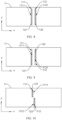
- FIG. 6 shows an embodiment in which projections of the first channel 111 and the second channel 112 fully overlap, where the first channel 111 and the second channel 112 are arranged along the direction z.
- the first inserting portion 121 and the second inserting portion 122 are spaced apart along the direction z.
- the first surface 1111 and the second surface 1121 respectively face toward the left side and the right side in the direction x of the end plate 11, and the first inserting portion 121 and the second inserting portion 122 respectively abut against the first surface 1111 and the second surface 1121.
- the projections of the first channel 111 and the second channel 112 fully overlap, to ensure smooth insertion of the first inserting portion 121 and the second inserting portion 122 into the first channel 111 and the second channel 112, in actual machining, the first inserting portion 121 and the second inserting portion 122 need to be stamped and thinned separately, so that the first inserting portion 121 and the second inserting portion 122 can abut against the first surface 1111 and the second surface 1121.
- the projections of the first channel 111 and the second channel 112 partially overlap, are spaced apart, or are arranged as connected in edge.
- FIG. 7 shows an embodiment in which projections of the first channel 111 and the second channel 112 partially overlap.
- the first channel 111 and the second channel 112 are arranged along the direction z.
- the first inserting portion 121 and the second inserting portion 122 are spaced apart along the direction z.
- the first channel 111 is located above the direction z relative to the second channel 112
- the first surface 1111 is located at an inner wall on the right side of the first channel 111
- the second surface 1121 is located at an inner wall on the left side of the second channel 112.
- the first inserting portion 121 fits with the first surface 1111 to restrict moving of the second inserting portion 122 to the right
- the second inserting portion 122 fits with the second surface 1121 to restrict moving of the first inserting portion 121 to the left, so that the first inserting portion 121 and the second inserting portion 122 restrain each other for positioning, implementing accurate positioning of the partition 12.
- FIG. 8 to FIG. 11 show embodiments in which projections of the first channel 111 and the second channel 112 are spaced apart.
- the first channel 111 and the second channel 112 may be arranged along the direction x.
- the first inserting portion 121 and the second inserting portion 122 are spaced apart along the direction x.
- the first channel 111 and the second channel 112 are arranged along the direction x, the first channel 111 is, relative to the second channel 112, on the right side of the end plate 11 in the width direction, the first surface 1111 is located at an inner wall on the lower side of the first channel 111, and the second surface 1121 is located at an inner wall on the upper side of the second channel 112.
- the first inserting portion 121 abuts against the first surface 1121, and the second inserting portion 122 abuts against the second surface 1121.
- the first channel 111 and the second channel 112 are arranged along the direction z, the first channel 111 is above the width direction of the end plate 11 relative to the second channel 112, the first surface 1111 is formed at an inner wall on the upper side of the first channel 111, and the second surface 1121 is formed at an inner wall on the lower side of the second channel 112, the first inserting portion 121 abuts against the first surface 1111, and the second inserting portion 122 abuts against the second surface 1121.
- the first channel 111 and the second channel 112 are arranged along the direction z, the first channel 111 is above the width direction of the end plate 11 relative to the second channel 112, the first surface 1111 is an inner wall on the left side of the first channel 111, and the second surface 1121 is an inner wall on the right side of the second channel 112.
- the first inserting portion 121 abuts against the first surface 1111, and the second inserting portion 122 abuts against the second surface 1121.
- a comparison result of substantial consistency indicates that the end plate 11 is manufactured up to standard; or a comparison result of large deviation indicates that the end plate 11 is not manufactured up to standard. In this way, a problem that the partition 12 cannot be accurately positioned due to manufacturing deviation of the end plate 11 can be eliminated.
- each channel may further be configured as having an inner wall for abutting against the inserting portion of the partition 12 in the width direction (namely, the direction x) of the end plate 11 and in the height direction (namely, the direction z) of the end plate 11, respectively.
- the first channel 111 is provided with a first surface 1111 in the width direction of the end plate 11, and the first channel 111 is also provided with a first surface 1111 in the height direction of the end plate 11.
- the partition 12 further includes a body 120, where each inserting portion has one end connected to an end portion of the body 120, and the first inserting portion 121 and the second inserting portion 122 are located at a same end portion of the body 120.
- An inserting portion bending region connects the body 120 and a connecting region, and an inserting portion connecting region is configured to insert into a corresponding channel and abut against an inner wall of this channel.
- Projections of the bending region on the bottom surface of the partition 12 in the height direction of the partition 12 may be of a plurality of shapes, for example, an arc shape, a wave shape, or a straight line leaning to one side in the thickness direction of the partition 12.
- the first inserting portion connecting region 1212 shifts toward a side in the thickness direction of the partition 12 relative to the body 120, and a step located between the connecting region and the body 120 is formed in the first inserting portion bending region 1211; and the second inserting portion connecting region 1222 shifts toward another side in the thickness direction of the partition 12 relative to the body 120, and a step located between the connecting region and the body 120 is formed in the first inserting portion bending region 1211.
- the foregoing bending region is configured to shield the connecting seam S in the thickness direction of the end plate 11 (or the width direction of the end plate 11 or the direction x).
- the second inserting portion bending region 1221 shifts rightward in the direction x relative to the body 120, so that a left side surface of the second inserting portion connecting region 1222 shifts rightward relative to a left side surface of the body 120.
- the left side surface of the second inserting portion connecting region 1222 abuts against the second surface 1121 of the second channel 112, and an extended surface of the second surface 1121 passes through the second inserting portion bending region 1221.
- the first channel 111 and the second channel 112 are arranged along the height direction of the end plate 11, the two projections of the first channel 111 and the second channel 112 on the bottom surface of the end plate 11 in the height direction of the end plate 11 are arranged as connected in edge.
- the connecting groove 113 is shown in dotted lines in the figure, and the connecting groove 113 extends along the width direction of the end plate 11 to communicate the first channel 111 and the second channel 112. As shown in FIG.
- the first channel 111 and the second channel 112 are arranged along the height direction of the end plate 11, the two projections of the first channel 111 and the second channel 112 on the bottom surface of the end plate 11 in the height direction of the end plate 11 partially overlap.
- the connecting groove 113 is shown in dotted lines in the figure, and the connecting groove 113 extends along the height direction of the end plate 11 to communicate the first channel 111 and the second channel 112.
- the connecting groove 113 mentioned in the embodiments of this application may be configured to penetrate the end plate 11 in the thickness direction of the end plate 11, or may be configured as a groove formed on a surface of the end plate 11 away from the partition 12.
- S100 Provide an end plate 11, where the end plate 11 is provided with at least two channels.
- step S 100 and step S200 are performed simultaneously.
- step S100 and step S200 may be performed in turn; for another example, step S200 may be performed before step S100; and for another example, step S 100 and step S200 are performed simultaneously.
- the first providing apparatus 31 is configured to provide an end plate 11, where the end plate 11 is provided with at least two channels.
- the assembly apparatus 33 is configured to insert the inserting portion into the channel.
Landscapes
- Chemical & Material Sciences (AREA)
- Chemical Kinetics & Catalysis (AREA)
- Electrochemistry (AREA)
- General Chemical & Material Sciences (AREA)
- Battery Mounting, Suspending (AREA)
Applications Claiming Priority (2)
| Application Number | Priority Date | Filing Date | Title |
|---|---|---|---|
| CN202110742242.8A CN113258197B (zh) | 2021-07-01 | 2021-07-01 | 箱体组件、电池、用电设备及箱体组件的制造方法和装置 |
| PCT/CN2021/130437 WO2023273101A1 (zh) | 2021-07-01 | 2021-11-12 | 箱体组件、电池、用电设备及箱体组件的制造方法和装置 |
Publications (2)
| Publication Number | Publication Date |
|---|---|
| EP4239772A1 true EP4239772A1 (de) | 2023-09-06 |
| EP4239772A4 EP4239772A4 (de) | 2024-10-16 |
Family
ID=77190320
Family Applications (1)
| Application Number | Title | Priority Date | Filing Date |
|---|---|---|---|
| EP21948027.4A Pending EP4239772A4 (de) | 2021-07-01 | 2021-11-12 | Gehäusekörperanordnung, batterie, elektrische vorrichtung und verfahren und vorrichtung zur herstellung der gehäusekörperanordnung |
Country Status (4)
| Country | Link |
|---|---|
| US (1) | US20230369707A1 (de) |
| EP (1) | EP4239772A4 (de) |
| CN (1) | CN113258197B (de) |
| WO (1) | WO2023273101A1 (de) |
Families Citing this family (4)
| Publication number | Priority date | Publication date | Assignee | Title |
|---|---|---|---|---|
| CN113258197B (zh) * | 2021-07-01 | 2021-12-07 | 江苏时代新能源科技有限公司 | 箱体组件、电池、用电设备及箱体组件的制造方法和装置 |
| CN116544578A (zh) * | 2022-01-26 | 2023-08-04 | 宁德时代新能源科技股份有限公司 | 围框、电池、用电设备、围框的制造方法及制造设备 |
| CN115084752B (zh) * | 2022-05-23 | 2023-12-15 | 东风柳州汽车有限公司 | 电池模组挡光结构及电池模组 |
| CN116885378A (zh) * | 2023-09-05 | 2023-10-13 | 宁德时代新能源科技股份有限公司 | 电池模组、电池和用电设备 |
Family Cites Families (6)
| Publication number | Priority date | Publication date | Assignee | Title |
|---|---|---|---|---|
| CN208256770U (zh) * | 2018-06-08 | 2018-12-18 | 宁德时代新能源科技股份有限公司 | 电池模组 |
| CN210156459U (zh) * | 2019-08-21 | 2020-03-17 | 东软睿驰汽车技术(沈阳)有限公司 | 一种电池模组及电池包 |
| CN211376714U (zh) * | 2019-12-19 | 2020-08-28 | 宁德时代新能源科技股份有限公司 | 电池模块、电池组以及装置 |
| CN211629183U (zh) * | 2020-03-31 | 2020-10-02 | 宁德时代新能源科技股份有限公司 | 箱体组件、电池模块、电池组及装置 |
| CN212625843U (zh) * | 2020-07-20 | 2021-02-26 | 北京车和家信息技术有限公司 | 电池模组框架、电池模组及车辆 |
| CN113258197B (zh) * | 2021-07-01 | 2021-12-07 | 江苏时代新能源科技有限公司 | 箱体组件、电池、用电设备及箱体组件的制造方法和装置 |
-
2021
- 2021-07-01 CN CN202110742242.8A patent/CN113258197B/zh active Active
- 2021-11-12 EP EP21948027.4A patent/EP4239772A4/de active Pending
- 2021-11-12 WO PCT/CN2021/130437 patent/WO2023273101A1/zh not_active Ceased
-
2023
- 2023-07-28 US US18/360,827 patent/US20230369707A1/en active Pending
Also Published As
| Publication number | Publication date |
|---|---|
| CN113258197B (zh) | 2021-12-07 |
| WO2023273101A1 (zh) | 2023-01-05 |
| CN113258197A (zh) | 2021-08-13 |
| US20230369707A1 (en) | 2023-11-16 |
| EP4239772A4 (de) | 2024-10-16 |
Similar Documents
| Publication | Publication Date | Title |
|---|---|---|
| US20230369707A1 (en) | Box assembly, battery, electric device, and manufacturing method and apparatus of box assembly | |
| KR102315847B1 (ko) | 용접 불량을 방지할 수 있는 전지팩 프레임을 포함하는 전지팩 및 이를 제조하기 위한 가압 지그 | |
| KR20220119696A (ko) | 전지 셀, 전지 및 전기 장치 | |
| JP2020508222A (ja) | レーザー溶接ジグ及びそれを含むレーザー溶接装置 | |
| US20230344059A1 (en) | Battery, electric device, and method and device for manufacturing battery | |
| EP4415114B1 (de) | Untere kunststoffanordnung, endkappenanordnung, energiespeichervorrichtung und elektronische vorrichtung | |
| KR20220125097A (ko) | 전지 모듈 및 이를 포함하는 전지팩 | |
| EP4560811A1 (de) | Strukturträger, gehäuse, batterie und elektrische vorrichtung | |
| KR20220103629A (ko) | 전지 모듈 및 이를 포함하는 전지팩 | |
| KR20220129323A (ko) | 전지 모듈 및 이를 포함하는 전지팩 | |
| EP4184690B1 (de) | Batteriemodul und batteriepack mit diesem | |
| US20230112464A1 (en) | End cover assembly, battery cell, battery, and electric apparatus | |
| EP4184696A1 (de) | Batteriemodul und batteriepack damit | |
| US20250062495A1 (en) | Battery cell, battery, and electric device | |
| EP4379919A1 (de) | Batteriepack | |
| US20240250365A1 (en) | Battery module and battery pack comprising same | |
| EP4485657A1 (de) | Batteriezelle und herstellungsverfahren und herstellungsvorrichtung dafür, batterie und stromverbrauchende vorrichtung | |
| EP4254591A1 (de) | Batterie, elektrische vorrichtung sowie verfahren und vorrichtung zur herstellung der batterie | |
| EP4546515A1 (de) | Batteriezelle, batterie und elektrische vorrichtung | |
| KR20230049496A (ko) | 배터리 모듈, 이러한 배터리 모듈을 포함하는 배터리 팩 및 이러한 배터리 팩을 포함하는 자동차 | |
| EP4645562A1 (de) | Batteriemodul, batteriepack und fahrzeug damit | |
| US20250260101A1 (en) | Battery cell including case, battery device comprising the same, and case manufacturing process | |
| EP4333155A2 (de) | Batteriemodul | |
| EP4693680A1 (de) | Batteriepack und fahrzeug damit | |
| EP4435955A1 (de) | Batteriepack |
Legal Events
| Date | Code | Title | Description |
|---|---|---|---|
| STAA | Information on the status of an ep patent application or granted ep patent |
Free format text: STATUS: THE INTERNATIONAL PUBLICATION HAS BEEN MADE |
|
| PUAI | Public reference made under article 153(3) epc to a published international application that has entered the european phase |
Free format text: ORIGINAL CODE: 0009012 |
|
| STAA | Information on the status of an ep patent application or granted ep patent |
Free format text: STATUS: REQUEST FOR EXAMINATION WAS MADE |
|
| 17P | Request for examination filed |
Effective date: 20230602 |
|
| AK | Designated contracting states |
Kind code of ref document: A1 Designated state(s): AL AT BE BG CH CY CZ DE DK EE ES FI FR GB GR HR HU IE IS IT LI LT LU LV MC MK MT NL NO PL PT RO RS SE SI SK SM TR |
|
| DAV | Request for validation of the european patent (deleted) | ||
| DAX | Request for extension of the european patent (deleted) | ||
| A4 | Supplementary search report drawn up and despatched |
Effective date: 20240918 |
|
| RIC1 | Information provided on ipc code assigned before grant |
Ipc: H01M 50/289 20210101ALI20240912BHEP Ipc: H01M 50/242 20210101ALI20240912BHEP Ipc: H01M 50/204 20210101ALI20240912BHEP Ipc: H01M 50/244 20210101AFI20240912BHEP |
|
| GRAP | Despatch of communication of intention to grant a patent |
Free format text: ORIGINAL CODE: EPIDOSNIGR1 |
|
| STAA | Information on the status of an ep patent application or granted ep patent |
Free format text: STATUS: GRANT OF PATENT IS INTENDED |
|
| RIC1 | Information provided on ipc code assigned before grant |
Ipc: H01M 50/244 20210101AFI20251013BHEP Ipc: H01M 50/204 20210101ALI20251013BHEP Ipc: H01M 50/242 20210101ALI20251013BHEP Ipc: H01M 50/289 20210101ALI20251013BHEP |
|
| INTG | Intention to grant announced |
Effective date: 20251103 |
|
| GRAS | Grant fee paid |
Free format text: ORIGINAL CODE: EPIDOSNIGR3 |
|
| GRAA | (expected) grant |
Free format text: ORIGINAL CODE: 0009210 |
|
| STAA | Information on the status of an ep patent application or granted ep patent |
Free format text: STATUS: THE PATENT HAS BEEN GRANTED |