EP4239604B1 - Vorrichtung zur bestimmung der dicke von papierblättern, vorrichtung zur identifizierung von papierblättern und vorrichtung zur handhabung von papierblättern - Google Patents
Vorrichtung zur bestimmung der dicke von papierblättern, vorrichtung zur identifizierung von papierblättern und vorrichtung zur handhabung von papierblättern Download PDFInfo
- Publication number
- EP4239604B1 EP4239604B1 EP23157891.5A EP23157891A EP4239604B1 EP 4239604 B1 EP4239604 B1 EP 4239604B1 EP 23157891 A EP23157891 A EP 23157891A EP 4239604 B1 EP4239604 B1 EP 4239604B1
- Authority
- EP
- European Patent Office
- Prior art keywords
- paper sheet
- vibration damping
- thickness
- detection
- damping member
- Prior art date
- Legal status (The legal status is an assumption and is not a legal conclusion. Google has not performed a legal analysis and makes no representation as to the accuracy of the status listed.)
- Active
Links
Images


Classifications
-
- G—PHYSICS
- G07—CHECKING-DEVICES
- G07D—HANDLING OF COINS OR VALUABLE PAPERS, e.g. TESTING, SORTING BY DENOMINATIONS, COUNTING, DISPENSING, CHANGING OR DEPOSITING
- G07D7/00—Testing specially adapted to determine the identity or genuineness of valuable papers or for segregating those which are unacceptable, e.g. banknotes that are alien to a currency
- G07D7/16—Testing the dimensions
- G07D7/164—Thickness
-
- G—PHYSICS
- G07—CHECKING-DEVICES
- G07D—HANDLING OF COINS OR VALUABLE PAPERS, e.g. TESTING, SORTING BY DENOMINATIONS, COUNTING, DISPENSING, CHANGING OR DEPOSITING
- G07D11/00—Devices accepting coins; Devices accepting, dispensing, sorting or counting valuable papers
- G07D11/20—Controlling or monitoring the operation of devices; Data handling
- G07D11/22—Means for sensing or detection
- G07D11/235—Means for sensing or detection for monitoring or indicating operating conditions; for detecting malfunctions
- G07D11/237—Means for sensing or detection for monitoring or indicating operating conditions; for detecting malfunctions for detecting transport malfunctions, e.g. jams or misfeeds
-
- G—PHYSICS
- G07—CHECKING-DEVICES
- G07F—COIN-FREED OR LIKE APPARATUS
- G07F19/00—Complete banking systems; Coded card-freed arrangements adapted for dispensing or receiving monies or the like and posting such transactions to existing accounts, e.g. automatic teller machines
- G07F19/20—Automatic teller machines [ATMs]
- G07F19/209—Monitoring, auditing or diagnose of functioning of ATMs
Definitions
- the banknote thickness detection apparatus includes a plurality of reference rollers, a plurality of detection rollers, and a plurality of displacement sensors that detect a displacement amount by which the detection rollers displace according to a thickness of a banknote with the reference rollers as a reference, when the banknote to be conveyed is sandwiched between the reference rollers and the detection rollers.
- Patent Literatures 2 to 5 each disclose further devices for measuring the thickness of paper sheets such as banknotes wherein the sheet is transported between a reference roller and a movable detection roller and which provide damping members.
- the upper unit is openable and closable and there is little restraint, it is not sufficient to suppress vibration of the detection rollers that occurs due to the impact at a time of the banknotes rushing in between the reference rollers and the detection rollers. If a space between the upper and lower rollers varies due to the vibration, the banknote thickness detection apparatus cannot correctly detect the thickness of banknotes.
- a vertical direction (an upward direction, upward) of an apparatus enclosure of an automatic cash transaction apparatus is a positive direction of a Z axis
- a direction from a user side (a front side, a front) of the apparatus enclosure toward an opposite side (a rear side, a'back) is a positive direction of a Y axis
- a direction toward a right side from a left side toward a user side of the apparatus enclosure is a positive direction of an X axis.
- a positive XYZ coordinate system in which the X axis, Y axis and Z axis are orthogonal to each other is used.
- a paper sheet thickness detection apparatus a paper sheet identification apparatus, a paper sheet handling apparatus, and an automatic paper sheet transaction apparatus
- a banknote thickness detection apparatus, a banknote identification apparatus, a banknote handling apparatus, and an automatic cash transaction apparatus that handle with banknotes as paper sheets will be described as examples.
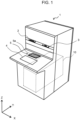
- a banknote handling apparatus 10 that processes banknotes is included. Deposit/withdrawal transactions of banknotes are performed according to opening and closing of a shutter 5a provided in a deposit/withdrawal section 5 of the banknote handling apparatus 10.
- FIG. 2 is a view showing an outline of an internal configuration of the automatic cash transaction apparatus 1 according to the embodiment.
- a processing mechanism of banknotes to be transacted is placed, and in a lower part, a storage mechanism of banknotes is placed.
- the deposit/withdrawal section 5 is placed, which receives deposit of banknotes set in a substantially standing position by a user, and sets banknotes in a substantially standing position to release the banknotes and allow a user to take out the banknotes.
- a banknote delivery section 5b that delivers banknotes inserted from above downward
- a banknote accumulation section 5c that accumulates banknotes for withdrawal or return that are conveyed from below are placed one behind the other.
- the banknote identification apparatus 30 can perform denomination discrimination and authenticity discrimination of banknotes conveyed on a conveyance path 30a from the front and the back from either direction.
- the banknote identification apparatus 30 can discriminate the denomination and authenticity of banknotes that are conveyed in both directions of deposit and withdrawal, and can discriminate whether or not the banknotes can be accepted and whether the banknotes can be dispensed.
- a plurality of storage units 70 that store banknotes by denomination are disposed. Some of the storage units 70 store banknotes that are determined to be acceptable in the banknote identification apparatus 30 by denomination. In addition, among the storage units 70, there is a storage unit 70 that temporarily stores banknotes that are determined as unacceptable in the banknote identification apparatus 30, a storage unit 70 that stores banknotes that are determined not to be withdrawable in the banknote identification apparatus 30, and a storage unit 70 that is used when banknotes are replenished from outside for withdrawal.
- FIG. 3 is a side view of the banknote identification apparatus 30 according to the embodiment seen from an X axis negative direction side
- FIG. 4 is a plan view of the banknote identification apparatus 30 according to the embodiment seen from a Z axis positive direction side
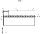
- FIG. 5 is a front view of the banknote identification apparatus 30 according to the embodiment seen from a Y axis negative direction side.
- the banknote identification apparatus 30 has an upper unit 30U in which components located above the conveyance path 30a are unitized, and a lower unit 30L in which components located below the conveyance path 30a are unitized, with the conveyance path 30a for banknotes therebetween.
- the banknote identification apparatus 30 is configured such that the upper unit 30U is attached at one end side (Y axis positive direction side) in the conveyance direction of banknotes to be openable and closable with respect to the lower unit 30L, with a rotation axis 30X parallel with the X axis as a rotation center.
- the upper unit 30U is openable in an arrow A ( FIG. 3 ) direction around the rotation axis 30X.
- the banknote identification apparatus 30 includes a thickness detection apparatus 30T ( FIG. 6 to FIG. 11 ) that detects a thickness of a banknote conveyed on the conveyance path 30a, in an inside in a vicinity of the rotation axis 30X (an area 30Z1 in FIG. 3 , a vicinity of area 30Z2 in FIG. 4 ).
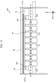
- FIG. 6 is a plan view of the thickness detection apparatus 30T according to the embodiment seen from a Z axis positive direction side.
- FIG. 7 is a perspective view of the thickness detection apparatus 30T according to the embodiment (state in which the upper and lower units are closed).
- FIG. 8 is a front view of the thickness detection apparatus 30T according to the embodiment seen from the Y axis positive direction side (state in which the upper and lower units are closed).
- FIG. 9 is a sectional side view of the thickness detection apparatus 30T according to the embodiment seen from an X axis negative direction side (state in which the upper and lower units are closed).
- FIG. 6 is a plan view of the thickness detection apparatus 30T according to the embodiment seen from a Z axis positive direction side.
- FIG. 7 is a perspective view of the thickness detection apparatus 30T according to the embodiment (state in which the upper and lower units are closed).
- FIG. 8 is a front view of the thickness detection apparatus 30T according to the embodiment seen from the Y axis positive direction side (state
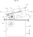
- FIG. 10 is a sectional side view of the thickness detection apparatus 30T according to the embodiment seen from the X axis negative direction side (state in which the upper and lower units are opened).
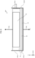
- FIG. 11 is a front view of the thickness detection apparatus 30T according to the embodiment seen from a Y axis positive direction (state in which the upper and lower units are opened).
- the plan view of the thickness detection apparatus 30T in FIG. 6 is a drawing in which illustration of the elements other than the thickness detection apparatus 30T is omitted in the plan view of the banknote identification apparatus 30 in FIG. 4 .
- the sectional side view of the thickness detection apparatus 30T in FIG. 9 is a drawing in which illustration of the elements other than the thickness detection apparatus 30T is omitted in the side view of the banknote identification apparatus 30 in FIG. 3 .
- the thickness detection apparatus 30T includes a bracket 31, a sensor substrate 32, a vibration damping member 33, a beam 34, a reference roller 35, a reference roller shaft 35X, a detection roller 36, a detection roller shaft 36X, and an enclosure 37.
- the enclosure 37 includes enclosures 37UR and 37UL on an upper unit 30U side of the banknote identification apparatus 30, and enclosures 37LR and 37LL on a lower unit 30L side.
- the enclosures 37UR and 37LR form an end surface on an X axis positive direction side of the thickness detection apparatus 30T.
- the enclosures 37UL and 37LL form an end surface on the X axis negative direction side of the thickness detection apparatus 30T.
- the enclosures 37UR and 37UL are perpendicularly attached to the beam 34 respectively from both ends in the X axis direction, of the beam 34.
- the bracket 31 is installed on and between the enclosures 37UR and 37UL, and supports the sensor substrate 32 on which a thickness sensor is placed as described later so that the thickness sensor faces the detection roller 36. Further, on the bracket 31, the vibration damping member 33 is provided as described later.
- the bracket 31, the sensor substrate 32, the vibration damping member 33, the beam 34, the detection roller 36, the detection roller shaft 36X, and the enclosures 37UR and 37UL configure an upper unit 30TU ( FIG. 7 ) of the thickness detection apparatus 30T.
- the reference roller 35 and the reference roller shaft 35X configure a lower unit 30TL ( FIG. 7 ) of the thickness detection apparatus 30T.
- the reference roller shaft 35X is a rotating shaft to which a rotational drive force is transmitted from a conveyance drive system (not illustrated) of a banknote conveyance mechanism, and is installed in and between the enclosures 37LR and 37LL along a width direction (X axis direction) of the conveyance path.
- the detection roller shaft 36X is installed in and between the enclosures 37LR and 37LL so as to face an upper side (Z axis positive direction) of the reference roller shaft 35X.
- a plurality of reference rollers 35 are placed on the reference roller shaft 35X on a lower side. Further, the same number of the detection rollers 36 as the number of the reference rollers 35 are disposed on the detection roller shaft 36X on an upper side to face the respective reference rollers 35.
- the detection roller 36 is configured by an outer ring formed of a cylindrical inelastic member such as metal an outer peripheral surface of which is not displaced, and an elastic member such as a spring or rubber that is elastically deformable in a direction to be pressed against the reference roller 35.
- the reference roller 35 is formed of metal, is provided with an outer surface as a reference surface that is not displaced, and each of the detection rollers 36 is faced to contact the reference surface. Subsequently, the respective detection rollers 36 are driven to rotate while being respectively pressed against the corresponding reference rollers 35. Further, when a banknote is sandwiched between the detection roller 36 and the reference roller 35, the outer ring of the detection roller 36 that faces the outer peripheral surface of the reference roller 35 as the reference surface is displaced in an upward direction (Z axis positive direction toward the detection roller shaft 36X from the reference roller shaft 35X) according to a thickness of the banknote.
- the sensor substrate 32 is provided, in which the thickness sensor (not illustrated) that is placed to face the respective detection rollers 36, and a sensor processing unit (not illustrated) that processes data obtained from the thickness sensor (not illustrated) are disposed.
- the thickness sensor is, for example, an eddy current magnetic field type displacement sensor that can detect a displacement amount by which the facing detection roller 36 elastically displaces in an up-down direction (Z axis direction) according to the thickness of a banknote sandwiched by the facing detection roller 36 with the reference roller 35.
- the sensor substrate 32 is supported by the bracket 31 so that the thickness sensor faces the detection rollers 36.
- the thickness detection apparatus 30T detects a thickness of a banknote based on the displacement amount of the detection roller 36 detected by the thickness sensor.
- the vibration damping member 33 is a member in a long shape that is provided on the bracket 31 to extend in a width direction (X axis direction) of the conveyance path 30a, but the shape is not limited to a long shape.
- the vibration damping member 33 is a viscoelastic member, but is not limited to a viscoelastic member.
- a plurality of vibration damping members 33 are stacked in layers in the Z axis positive direction toward the beam 34, onto the bracket 31, but the vibration damping member 33 may be in a single layer.
- the vibration damping member 33 is a damper that suppresses vibration of the detection rollers 36 that occurs due to impact at a time of banknotes rushing in between the reference rollers 35 and the detection rollers 36.
- the vibration damping effect can be obtained even if the vibration damping member 33 is placed in any place in the upper unit 30TU without being limited to modes shown in FIG. 7 to FIG. 9 , as long as the vibration damping member 33 is in a positional relationship in which the vibration damping member 33 viscously deforms in a vibration direction (or a vibration damping direction) of the detection roller 36.
- FIG. 11 is a front view of the thickness detection apparatus 30T in a state in which the upper and lower units shown in FIG. 10 are opened seen from the Y axis positive direction.
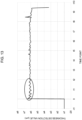
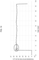
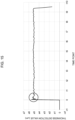
- FIG. 10 to FIG. 15 each shows a time change of a thickness detection value due to vibration of the detection roller 36 at a time of conveying a banknote with a predetermined thickness, with a time point taken on a horizontal axis, and the thickness detection value of the detection roller 36 taken on a vertical axis.
- FIG. 12 is a graph showing a change of the thickness detection value due to vibration of the detection roller 36 of the thickness detection apparatus 30T of the comparative example in which the vibration damping member 33 is not provided.
- FIG. 13 is a graph showing a change of a thickness detection value due to vibration of the detection roller 36 of the thickness detection apparatus 30T of example 1 in which the vibration damping member 33 with the viscosity coefficient smaller than the predetermined value was pressed with the beam 34.
- the vibration damping member 33 pressed by the beam 34 can be said as functioning as a reinforcement member that suppresses vibration.
- FIG. 14 is a graph showing a change of a thickness detection value due to the vibration of the detection roller 36 of the thickness detection apparatus 30T of example 2 in which the vibration damping member 33 with the viscosity coefficient equal to or larger than the predetermined value is provided.
- an amplitude is larger but a converging time period of the vibration is further shorter than in Example 1.
- the vibration damping member 33 can be said as functioning as a damper that absorbs vibration.
- FIG. 15 is a graph showing a change of a thickness detection value due to vibration of the detection roller 36 of the thickness detection apparatus 30T in Example 3 in which the vibration damping member 33 with the viscosity coefficient equal to or larger than the predetermined value was pressed with the beam 34.
- the vibration damping member 33 has higher damper performance for absorbing vibration, and converges the vibration of the detection roller 36 in a shorter time period, in order of Example 3, Example 2, and Example 1. Therefore, according to these examples, it is possible to enhance precision of thickness detection of banknotes by suppressing vibration of the detection roller 36 that occurs due to impact at the time of the banknotes rushing in between the reference roller 35 and the detection roller 36. Further, even with the configuration in which the banknote identification apparatus 30 and the thickness detection apparatus 30T are divided into the upper units 30U and 30TU, and the lower units 30L and 30LT, and attached to be openable and closable, it is possible to suppress vibration of the detection roller 36. Therefore, it is possible to achieve compatibility with maintainability at a time of removing a jam of banknotes that occurs between the reference roller 35 and the detection roller 36.
- the present invention is not limited to the aforementioned embodiment, but includes various modified examples.
- the aforementioned embodiment is described in detail to make the present invention easy to understand, and the present invention is not necessarily limited to the embodiment including all the configurations that are described.
- Each process shown in the embodiment may be properly distributed or integrated based on processing efficiency or implementation efficiency.
Landscapes
- Physics & Mathematics (AREA)
- General Physics & Mathematics (AREA)
- Business, Economics & Management (AREA)
- Accounting & Taxation (AREA)
- Finance (AREA)
- Inspection Of Paper Currency And Valuable Securities (AREA)
- Controlling Sheets Or Webs (AREA)
Claims (5)
- Vorrichtung (30) zum Detektieren einer Papierbogendicke, die konfiguriert ist, die Dicke eines Papierbogens zu detektieren, wobei die Vorrichtung Folgendes umfasst:eine erste Einheit (30TL), die eine Referenzwalze (35) umfasst; undeine zweite Einheit (30TU), die Folgendes umfasst: eine Detektionswalze (36), die konfiguriert ist, den Papierbogen zwischen dieser und der Referenzwalze (35) anzuordnen, um den Papierbogen zu transportieren, und sich in Bezug auf die Referenzwalze (35) entsprechend einer Dicke des Papierbogens zu verlagern, und einen Dickensensor (30T), der konfiguriert ist, die Dicke des Papierbogens auf der Basis eines Verlagerungsbetrags der Detektionswalze (36) zu detektieren, wobeidie erste Einheit (30TL) und die zweite Einheit (30TU) übereinander angeordnet sind, so dass der Papierbogen zwischen der Referenzwalze (35) und der Detektionswalze (36) angeordnet ist, um einen Transportpfad (30a) für den Papierbogen zu bilden, und so zusammengebaut sind, dass sie geöffnet und geschlossen werden können, wobei eine Drehachse (30X) an einer Stirnseite des Transportpfads (30a) als Zentrum vorgesehen ist, unddie zweite Einheit (30TU) ein Schwingungsdämpfungselement (33) am Dickensensor (30T) umfasst,dadurch gekennzeichnet, dassdas Schwingungsdämpfungselement (33) so konfiguriert ist, dass es sich in einer Schwingungsdämpfungsrichtung viskos verformt, um eine Schwingung der Detektionswalze (36) zu dämpfen,wobei die zweite Einheit (30TU) eine Halterung (31) umfasst, die konfiguriert ist, den Dickensensor (30T) so zu tragen, dass der Dickensensor (30T) zur Detektionswalze (36) zeigt, unddas Schwingungsdämpfungselement (33) an der Halterung (31) angeordnet ist,ein Presselement (34) konfiguriert ist, auf das Schwingungsdämpfungselement (33) mit einer Anordnungsfläche des Schwingungsdämpfungselements (33) zu pressen, und eine höhere Steifigkeit als das Schwingungsdämpfungselement (33) aufweist.
- Vorrichtung (30) zum Detektieren einer Papierbogendicke nach Anspruch 1, wobei
ein Viskositätskoeffizient des Schwingungsdämpfungselements (33) gleich einem zuvor festgelegten Wert oder größer ist. - Vorrichtung (30) zum Detektieren einer Papierbogendicke nach Anspruch 2, wobeidas Presselement (34) ein existierendes Element der zweiten Einheit (30TU) ist, das eine weitere Funktion neben dem Pressen auf das Schwingungsdämpfungselement (33) hat, unddas Schwingungsdämpfungselement (33) in einen Raum vor der Anordnungsfläche des Presselements (34) eingesetzt ist.
- Papierbogen-Identifikationsvorrichtung, die die Vorrichtung (30) zum Detektieren einer Papierbogendicke nach einem der Ansprüche 1 bis 3 umfasst.
- Papierbogen-Handhabungsvorrichtung, die die Papierbogen-Identifikationsvorrichtung nach Anspruch 4 umfasst.
Applications Claiming Priority (1)
| Application Number | Priority Date | Filing Date | Title |
|---|---|---|---|
| JP2022032201A JP7839657B2 (ja) | 2022-03-02 | 紙葉類厚み検出装置、紙葉類識別装置、及び紙葉類取扱装置 |
Publications (2)
| Publication Number | Publication Date |
|---|---|
| EP4239604A1 EP4239604A1 (de) | 2023-09-06 |
| EP4239604B1 true EP4239604B1 (de) | 2025-07-02 |
Family
ID=85328882
Family Applications (1)
| Application Number | Title | Priority Date | Filing Date |
|---|---|---|---|
| EP23157891.5A Active EP4239604B1 (de) | 2022-03-02 | 2023-02-22 | Vorrichtung zur bestimmung der dicke von papierblättern, vorrichtung zur identifizierung von papierblättern und vorrichtung zur handhabung von papierblättern |
Country Status (2)
| Country | Link |
|---|---|
| EP (1) | EP4239604B1 (de) |
| CN (1) | CN116704663B (de) |
Citations (2)
| Publication number | Priority date | Publication date | Assignee | Title |
|---|---|---|---|---|
| JP2000357254A (ja) * | 1999-06-15 | 2000-12-26 | Toshiba Corp | 紙葉類の厚さ検知装置 |
| JP2020059559A (ja) * | 2018-10-04 | 2020-04-16 | グローリー株式会社 | 厚み検知装置および紙葉類処理装置 |
Family Cites Families (11)
| Publication number | Priority date | Publication date | Assignee | Title |
|---|---|---|---|---|
| AT334118B (de) * | 1975-07-15 | 1976-12-27 | Gao Ges Automation Org | Messvorrichtung zum messen von dickenunterschieden in aufzeichnungstragern, wie banknoten u.dgl. |
| US4378109A (en) * | 1979-09-19 | 1983-03-29 | Tokyo Shibaura Denki Kabushiki Kaisha | Device for detecting the thickness of a paper sheet |
| US6386770B1 (en) * | 1999-01-07 | 2002-05-14 | Nec Corporation & Ntt Data Corporation | Printer |
| JP3923726B2 (ja) * | 1999-12-15 | 2007-06-06 | 株式会社東芝 | 紙葉類の特性を検知する特性検知装置 |
| KR100547431B1 (ko) * | 2003-08-01 | 2006-01-31 | 엘지엔시스(주) | 매체의 두께검지장치 |
| DE102005000082A1 (de) * | 2005-06-29 | 2007-01-04 | Voith Patent Gmbh | Wickelmaschine |
| FI118858B (fi) * | 2005-09-30 | 2008-04-15 | Metso Paper Inc | Järjestelmä paperikoneen osan värähtelyiden vaimentamiseksi ja estämiseksi |
| JP2011184124A (ja) * | 2010-03-05 | 2011-09-22 | Toyo Networks & System Integration Co Ltd | 紙葉類の厚み検知装置、紙葉類処理装置、及び紙葉類取扱装置 |
| JP5997018B2 (ja) | 2012-11-21 | 2016-09-21 | 日立オムロンターミナルソリューションズ株式会社 | 紙葉類厚み検出装置および紙葉類識別装置 |
| JP2014238504A (ja) * | 2013-06-07 | 2014-12-18 | 株式会社リコー | 画像形成装置 |
| CN204595984U (zh) * | 2015-04-16 | 2015-08-26 | 广州中智融通金融科技有限公司 | 一种薄片介质厚度检测装置 |
-
2023
- 2023-02-22 EP EP23157891.5A patent/EP4239604B1/de active Active
- 2023-02-23 CN CN202310154740.XA patent/CN116704663B/zh active Active
Patent Citations (2)
| Publication number | Priority date | Publication date | Assignee | Title |
|---|---|---|---|---|
| JP2000357254A (ja) * | 1999-06-15 | 2000-12-26 | Toshiba Corp | 紙葉類の厚さ検知装置 |
| JP2020059559A (ja) * | 2018-10-04 | 2020-04-16 | グローリー株式会社 | 厚み検知装置および紙葉類処理装置 |
Also Published As
| Publication number | Publication date |
|---|---|
| JP2023128095A (ja) | 2023-09-14 |
| CN116704663B (zh) | 2025-10-31 |
| EP4239604A1 (de) | 2023-09-06 |
| CN116704663A (zh) | 2023-09-05 |
Similar Documents
| Publication | Publication Date | Title |
|---|---|---|
| CN102410823B (zh) | 纸张类厚度检测装置及纸币处理装置 | |
| CN101211478B (zh) | 纸币循环机 | |
| CN106251473B (zh) | 金融设备及媒介物堆积装置 | |
| JP6052059B2 (ja) | 媒体集積装置及び媒体処理装置 | |
| KR20140088946A (ko) | 수표 입출금용 카세트 및 이를 구비한 금융자동화기기 | |
| JP6281406B2 (ja) | 厚み検出装置及び媒体取引装置 | |
| EP4239604B1 (de) | Vorrichtung zur bestimmung der dicke von papierblättern, vorrichtung zur identifizierung von papierblättern und vorrichtung zur handhabung von papierblättern | |
| JP5898041B2 (ja) | 搬送ユニット付き紙葉類取扱装置 | |
| JP7839657B2 (ja) | 紙葉類厚み検出装置、紙葉類識別装置、及び紙葉類取扱装置 | |
| CN105741408B (zh) | 介质处理装置 | |
| KR101775779B1 (ko) | 매체 처리 장치 및 금융 기기 | |
| KR200388998Y1 (ko) | 출금부에서의 종이매체 홀딩구조 | |
| JP5857077B2 (ja) | 紙葉類処理装置および遊技媒体貸出装置 | |
| KR200411492Y1 (ko) | 잼 방지 기능을 갖는 금융자동화기기 | |
| KR102887789B1 (ko) | 금용자동화기기용 카세트 | |
| JP6003555B2 (ja) | 媒体搬送装置 | |
| JP5857080B2 (ja) | 紙葉類処理装置および遊技媒体貸出装置 | |
| JP5857079B2 (ja) | 紙葉類処理装置および遊技媒体貸出装置 | |
| EP4624391A1 (de) | Medienführung und -führung | |
| KR101799393B1 (ko) | 매체 처리 장치 및 이를 구비한 금융기기 | |
| KR20250146822A (ko) | 금용자동화기기용 카세트 | |
| KR101001759B1 (ko) | 금융자동화기기 | |
| KR20190021593A (ko) | 매체 처리 장치 및 이를 구비하는 금융기기 | |
| KR101932189B1 (ko) | 매체 입금장치 및 금융기기 | |
| JP5879371B2 (ja) | 紙葉類処理装置および遊技媒体貸出装置 |
Legal Events
| Date | Code | Title | Description |
|---|---|---|---|
| PUAI | Public reference made under article 153(3) epc to a published international application that has entered the european phase |
Free format text: ORIGINAL CODE: 0009012 |
|
| STAA | Information on the status of an ep patent application or granted ep patent |
Free format text: STATUS: REQUEST FOR EXAMINATION WAS MADE |
|
| 17P | Request for examination filed |
Effective date: 20230317 |
|
| AK | Designated contracting states |
Kind code of ref document: A1 Designated state(s): AL AT BE BG CH CY CZ DE DK EE ES FI FR GB GR HR HU IE IS IT LI LT LU LV MC ME MK MT NL NO PL PT RO RS SE SI SK SM TR |
|
| STAA | Information on the status of an ep patent application or granted ep patent |
Free format text: STATUS: EXAMINATION IS IN PROGRESS |
|
| 17Q | First examination report despatched |
Effective date: 20240523 |
|
| GRAP | Despatch of communication of intention to grant a patent |
Free format text: ORIGINAL CODE: EPIDOSNIGR1 |
|
| STAA | Information on the status of an ep patent application or granted ep patent |
Free format text: STATUS: GRANT OF PATENT IS INTENDED |
|
| INTG | Intention to grant announced |
Effective date: 20250221 |
|
| RIN1 | Information on inventor provided before grant (corrected) |
Inventor name: MIURA, YOUSUKE Inventor name: NGUYEN, VIET |
|
| GRAS | Grant fee paid |
Free format text: ORIGINAL CODE: EPIDOSNIGR3 |
|
| GRAA | (expected) grant |
Free format text: ORIGINAL CODE: 0009210 |
|
| STAA | Information on the status of an ep patent application or granted ep patent |
Free format text: STATUS: THE PATENT HAS BEEN GRANTED |
|
| AK | Designated contracting states |
Kind code of ref document: B1 Designated state(s): AL AT BE BG CH CY CZ DE DK EE ES FI FR GB GR HR HU IE IS IT LI LT LU LV MC ME MK MT NL NO PL PT RO RS SE SI SK SM TR |
|
| REG | Reference to a national code |
Ref country code: GB Ref legal event code: FG4D |
|
| REG | Reference to a national code |
Ref country code: CH Ref legal event code: EP |
|
| REG | Reference to a national code |
Ref country code: DE Ref legal event code: R096 Ref document number: 602023004380 Country of ref document: DE |
|
| REG | Reference to a national code |
Ref country code: IE Ref legal event code: FG4D |
|
| REG | Reference to a national code |
Ref country code: NL Ref legal event code: MP Effective date: 20250702 |
|
| PG25 | Lapsed in a contracting state [announced via postgrant information from national office to epo] |
Ref country code: PT Free format text: LAPSE BECAUSE OF FAILURE TO SUBMIT A TRANSLATION OF THE DESCRIPTION OR TO PAY THE FEE WITHIN THE PRESCRIBED TIME-LIMIT Effective date: 20251103 |
|
| PG25 | Lapsed in a contracting state [announced via postgrant information from national office to epo] |
Ref country code: NL Free format text: LAPSE BECAUSE OF FAILURE TO SUBMIT A TRANSLATION OF THE DESCRIPTION OR TO PAY THE FEE WITHIN THE PRESCRIBED TIME-LIMIT Effective date: 20250702 |
|
| PG25 | Lapsed in a contracting state [announced via postgrant information from national office to epo] |
Ref country code: IS Free format text: LAPSE BECAUSE OF FAILURE TO SUBMIT A TRANSLATION OF THE DESCRIPTION OR TO PAY THE FEE WITHIN THE PRESCRIBED TIME-LIMIT Effective date: 20251102 |
|
| PG25 | Lapsed in a contracting state [announced via postgrant information from national office to epo] |
Ref country code: NO Free format text: LAPSE BECAUSE OF FAILURE TO SUBMIT A TRANSLATION OF THE DESCRIPTION OR TO PAY THE FEE WITHIN THE PRESCRIBED TIME-LIMIT Effective date: 20251002 |
|
| REG | Reference to a national code |
Ref country code: LT Ref legal event code: MG9D |
|
| PG25 | Lapsed in a contracting state [announced via postgrant information from national office to epo] |
Ref country code: FI Free format text: LAPSE BECAUSE OF FAILURE TO SUBMIT A TRANSLATION OF THE DESCRIPTION OR TO PAY THE FEE WITHIN THE PRESCRIBED TIME-LIMIT Effective date: 20250702 |
|
| PG25 | Lapsed in a contracting state [announced via postgrant information from national office to epo] |
Ref country code: HR Free format text: LAPSE BECAUSE OF FAILURE TO SUBMIT A TRANSLATION OF THE DESCRIPTION OR TO PAY THE FEE WITHIN THE PRESCRIBED TIME-LIMIT Effective date: 20250702 |
|
| PG25 | Lapsed in a contracting state [announced via postgrant information from national office to epo] |
Ref country code: GR Free format text: LAPSE BECAUSE OF FAILURE TO SUBMIT A TRANSLATION OF THE DESCRIPTION OR TO PAY THE FEE WITHIN THE PRESCRIBED TIME-LIMIT Effective date: 20251003 |
|
| PG25 | Lapsed in a contracting state [announced via postgrant information from national office to epo] |
Ref country code: CZ Free format text: LAPSE BECAUSE OF FAILURE TO SUBMIT A TRANSLATION OF THE DESCRIPTION OR TO PAY THE FEE WITHIN THE PRESCRIBED TIME-LIMIT Effective date: 20250702 Ref country code: SE Free format text: LAPSE BECAUSE OF FAILURE TO SUBMIT A TRANSLATION OF THE DESCRIPTION OR TO PAY THE FEE WITHIN THE PRESCRIBED TIME-LIMIT Effective date: 20250702 |
|
| PG25 | Lapsed in a contracting state [announced via postgrant information from national office to epo] |
Ref country code: LV Free format text: LAPSE BECAUSE OF FAILURE TO SUBMIT A TRANSLATION OF THE DESCRIPTION OR TO PAY THE FEE WITHIN THE PRESCRIBED TIME-LIMIT Effective date: 20250702 |
|
| PG25 | Lapsed in a contracting state [announced via postgrant information from national office to epo] |
Ref country code: BG Free format text: LAPSE BECAUSE OF FAILURE TO SUBMIT A TRANSLATION OF THE DESCRIPTION OR TO PAY THE FEE WITHIN THE PRESCRIBED TIME-LIMIT Effective date: 20250702 Ref country code: PL Free format text: LAPSE BECAUSE OF FAILURE TO SUBMIT A TRANSLATION OF THE DESCRIPTION OR TO PAY THE FEE WITHIN THE PRESCRIBED TIME-LIMIT Effective date: 20250702 |
|
| PG25 | Lapsed in a contracting state [announced via postgrant information from national office to epo] |
Ref country code: RS Free format text: LAPSE BECAUSE OF FAILURE TO SUBMIT A TRANSLATION OF THE DESCRIPTION OR TO PAY THE FEE WITHIN THE PRESCRIBED TIME-LIMIT Effective date: 20251002 |
|
| PG25 | Lapsed in a contracting state [announced via postgrant information from national office to epo] |
Ref country code: ES Free format text: LAPSE BECAUSE OF FAILURE TO SUBMIT A TRANSLATION OF THE DESCRIPTION OR TO PAY THE FEE WITHIN THE PRESCRIBED TIME-LIMIT Effective date: 20250702 |