EP4239446A2 - Elektronische vorrichtungsanordnung und erweiterungskomponente dafür - Google Patents
Elektronische vorrichtungsanordnung und erweiterungskomponente dafür Download PDFInfo
- Publication number
- EP4239446A2 EP4239446A2 EP23155307.4A EP23155307A EP4239446A2 EP 4239446 A2 EP4239446 A2 EP 4239446A2 EP 23155307 A EP23155307 A EP 23155307A EP 4239446 A2 EP4239446 A2 EP 4239446A2
- Authority
- EP
- European Patent Office
- Prior art keywords
- circuit board
- side edge
- expansion component
- top plate
- heat dissipation
- Prior art date
- Legal status (The legal status is an assumption and is not a legal conclusion. Google has not performed a legal analysis and makes no representation as to the accuracy of the status listed.)
- Granted
Links
Images







Classifications
-
- H—ELECTRICITY
- H05—ELECTRIC TECHNIQUES NOT OTHERWISE PROVIDED FOR
- H05K—PRINTED CIRCUITS; CASINGS OR CONSTRUCTIONAL DETAILS OF ELECTRIC APPARATUS; MANUFACTURE OF ASSEMBLAGES OF ELECTRICAL COMPONENTS
- H05K1/00—Printed circuits
- H05K1/02—Details
- H05K1/14—Structural association of two or more printed circuits
- H05K1/141—One or more single auxiliary printed circuits mounted on a main printed circuit, e.g. modules, adapters
-
- G—PHYSICS
- G06—COMPUTING OR CALCULATING; COUNTING
- G06F—ELECTRIC DIGITAL DATA PROCESSING
- G06F1/00—Details not covered by groups G06F3/00 - G06F13/00 and G06F21/00
- G06F1/16—Constructional details or arrangements
- G06F1/20—Cooling means
- G06F1/203—Cooling means for portable computers, e.g. for laptops
-
- G—PHYSICS
- G06—COMPUTING OR CALCULATING; COUNTING
- G06F—ELECTRIC DIGITAL DATA PROCESSING
- G06F1/00—Details not covered by groups G06F3/00 - G06F13/00 and G06F21/00
- G06F1/16—Constructional details or arrangements
- G06F1/1613—Constructional details or arrangements for portable computers
- G06F1/1632—External expansion units, e.g. docking stations
-
- H—ELECTRICITY
- H05—ELECTRIC TECHNIQUES NOT OTHERWISE PROVIDED FOR
- H05K—PRINTED CIRCUITS; CASINGS OR CONSTRUCTIONAL DETAILS OF ELECTRIC APPARATUS; MANUFACTURE OF ASSEMBLAGES OF ELECTRICAL COMPONENTS
- H05K1/00—Printed circuits
- H05K1/02—Details
- H05K1/14—Structural association of two or more printed circuits
- H05K1/144—Stacked arrangements of planar printed circuit boards
-
- H—ELECTRICITY
- H05—ELECTRIC TECHNIQUES NOT OTHERWISE PROVIDED FOR
- H05K—PRINTED CIRCUITS; CASINGS OR CONSTRUCTIONAL DETAILS OF ELECTRIC APPARATUS; MANUFACTURE OF ASSEMBLAGES OF ELECTRICAL COMPONENTS
- H05K3/00—Apparatus or processes for manufacturing printed circuits
- H05K3/36—Assembling printed circuits with other printed circuits
- H05K3/368—Assembling printed circuits with other printed circuits parallel to each other
-
- H—ELECTRICITY
- H05—ELECTRIC TECHNIQUES NOT OTHERWISE PROVIDED FOR
- H05K—PRINTED CIRCUITS; CASINGS OR CONSTRUCTIONAL DETAILS OF ELECTRIC APPARATUS; MANUFACTURE OF ASSEMBLAGES OF ELECTRICAL COMPONENTS
- H05K5/00—Casings, cabinets or drawers for electric apparatus
- H05K5/06—Hermetically-sealed casings
- H05K5/065—Hermetically-sealed casings sealed by encapsulation, e.g. waterproof resin forming an integral casing, injection moulding
Definitions
- the present invention relates to an electronic device assembly and an expansion component thereof.
- the expansion component includes a first case, a first circuit board, and at least one first connector.
- the host includes a second case, a main circuit board, and a main connector.
- the first case includes a top plate and a bottom plate that are opposite to each other, where a first accommodating space is formed between the top plate and the bottom plate, and the top plate is provided with an opening.
- the first circuit board is arranged in the first accommodating space.
- the first connector is electrically connected to the first circuit board, and the first connector is exposed from the top plate at the opening.
- the second case includes a first surface and a second surface that are opposite to each other, where a second accommodating space is formed between the first surface and the second surface.
- the main circuit board is arranged in the second accommodating space.
- the main connector is electrically connected to the main circuit board and exposed from the second surface.
- the second surface of the second case covers the top plate of the first case and the opening, and the first connector is electrically connected to the main connector.
- the opening is located in the middle of the expansion component, and the expansion component further includes a waterproof member that is arranged around the opening.
- the expansion component further includes a partition, where the partition is parallel to the top plate and is arranged in the first accommodating space, and divides the first accommodating space of the expansion component into an upper compartment and a lower compartment.
- the electronic device assembly further includes a second circuit board, batteries, and a second connector, where the first circuit board is arranged in the upper compartment, the second circuit board and the batteries are arranged in the lower compartment and are electrically connected to each other, and the second connector penetrates the partition and is electrically connected to the first circuit board and the second circuit board.
- the present invention further provides an expansion component, including a case, two openings, a partition, and a plurality of electronic components.
- the case includes a bottom plate, a top plate, and a first side edge, a second side edge, a third side edge, and a fourth side edge that are sequentially connected, where the first side edge, the second side edge, the third side edge, and the fourth side edge are respectively connected to the bottom plate and the top plate to form an accommodating space.
- the openings run through the top plate and are located on the first side edge, where the two openings are respectively adjacent to the second side edge and the fourth side edge.
- the partition is arranged in the accommodating space and parallel to the bottom plate, and the partition divides the accommodating space into an upper compartment and a lower compartment.
- the electronic components are arranged in the accommodating space and scattered in the upper compartment and the lower compartment.
- the expansion component further includes two assembly grooves, respectively corresponding to the two openings, where the two assembly grooves are connected to the top plate and are recessed toward the bottom plate.
- the expansion component further includes two fans, respectively assembled in the two assembly grooves.
- two heat dissipation pipe grooves are recessed on a side of the top plate away from the bottom plate, and the two heat dissipation pipe grooves respectively extend from the third side edge to the corresponding openings.
- the electronic components include a first circuit board, a second circuit board, and a connector, where the first circuit board is accommodated in the upper compartment and assembled on a side of the top plate toward the bottom plate, the second circuit board is accommodated in the lower compartment, and the connector penetrates the partition and is electrically connected to the first circuit board and the second circuit board.
- the electronic components further include a plurality of disk arrays, accommodated in the upper compartment and electrically connected to the first circuit board, where the disk arrays are respectively assembled on two sides of the first circuit board and located between one assembly groove and the third side edge.
- two heat dissipation pipes are arranged on a side of the top plate away from the bottom plate, and the two heat dissipation pipes correspond to the disk arrays.
- the expansion component further includes two waterproof cover plates, correspondingly covering the two openings.
- the electronic components include a first circuit board, a bus apparatus, at least one fan, a second circuit board, and a connector, where the first circuit board is accommodated in the upper compartment and assembled on a side of the top plate toward the bottom plate, and the bus apparatus is accommodated in the upper compartment and electrically connected to the first circuit board.
- the fan is accommodated in the upper compartment and electrically connected to the first circuit board.
- the second circuit board is accommodated in the lower compartment.
- the connector penetrates the partition and is electrically connected to the first circuit board and the second circuit board.
- the electronic components further include at least one battery, accommodated in the lower compartment and electrically connected to the second circuit board.
- the present invention provides another expansion component, including a case, two openings, a partition, a first circuit board, a second circuit board, at least one battery, and a connector.
- the case includes a bottom plate, a top plate, and a first side edge, a second side edge, a third side edge, and a fourth side edge that are sequentially connected, where the first side edge, the second side edge, the third side edge, and the fourth side edge are respectively connected to the bottom plate and the top plate to form an accommodating space.
- the openings run through the top plate and are located on the first side edge, and the two openings are respectively adjacent to the second side edge and the fourth side edge.
- the partition is arranged in the accommodating space and parallel to the bottom plate, and divides the accommodating space into an upper compartment and a lower compartment.
- the first circuit board is accommodated in the upper compartment
- the second circuit board is accommodated in the lower compartment
- the battery is accommodated in the lower compartment and electrically connected to the second circuit board
- the connector penetrates the partition and is electrically connected to the first circuit board and the second circuit board.
- the expansion component further includes two bus apparatuses and two fans, both accommodated in the upper compartment and electrically connected to the first circuit board.
- FIG. 1 is a schematic three-dimensional external view of an embodiment of an electronic device assembly according to the present invention
- FIG. 2 is a first schematic three-dimensional exploded diagram of an embodiment of an electronic device assembly according to the present invention
- FIG. 3 is a second schematic three-dimensional exploded diagram of an embodiment of an electronic device assembly according to the present invention
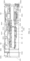
- FIG. 4 is a schematic cross-sectional view drawn along a division line 4-4 in FIG. 1 .
- the present invention provides an electronic device assembly, including a plurality of overlapping electronic devices E.
- the electronic devices E include cases H and electronic components A, each of the cases H has an accommodating space S, the electronic components A are assembled in the accommodating space S of each of the cases H, and the electronic components A in adjacent cases H are assembled in an overlapping manner in the two cases H and can be electrically connected to each other. Therefore, the electronic device assembly may use the accommodating spaces S of the plurality of electronic devices E without external wiring to increase a quantity and types of assembled electronic components A, thereby satisfying diversified electronic function expansion.
- the cases H and different electronic components A arranged inside the cases may be matched and combined into electronic devices E with different function orientations.
- the electronic components A may be circuit boards, connectors, storage elements, or power supply elements with different function orientations.
- the electronic device assembly includes two electronic devices E, where each of the electronic devices E includes a case H.
- each of the electronic devices E includes a case H.
- An example in which the two electronic devices E are respectively an expansion component E1 and a host E2 is used below for description, but the present invention is not limited thereto.
- the cases H include a first case H1 and a second case H2, where the first case H1 includes a first accommodating space S1, the second case H2 includes a second accommodating space S2, the first case H1 is a part of the expansion component E1, and the second case H2 is a part of the host E2.
- the electronic device assembly includes the expansion component E1 and the host E2.
- the expansion component E1 includes the first accommodating space S1
- the host E2 includes the second accommodating space S2
- different electronic components A are respectively arranged in the first accommodating space S1 and the second accommodating space S2.
- one surface of the expansion component E1 abuts against and is electrically connected to one surface of the host E2, to increase spaces of the electronic device assembly for assembling the electronic components A and functions that can be provided by the electronic device assembly.
- the electronic components A include a first circuit board A1 and a first connector A2 arranged in the first accommodating space S1 of the expansion component E1 and a main circuit board A3 and a main connector A4 arranged in the second accommodating space S2 of the host E2.
- the main circuit board A3 may be a main board
- the first circuit board A1 is various expansion circuit boards that can cooperate with the main board, but the present invention is not limited thereto.
- the expansion component E1 includes the first case H1, the first circuit board A1, and at least one first connector A2.
- the first case H1 includes a top plate H11 and a bottom plate H12 that are opposite to each other, where the first accommodating space S1 is formed between the top plate H11 and the bottom plate H12, and the top plate H11 is provided with an opening H111.
- the first circuit board A1 is arranged in the first accommodating space S1.
- the first connector A2 is electrically connected to the first circuit board A1, and the first connector A2 is exposed from the top plate H11 at the opening H111. It should be noted that as shown in FIG.
- the opening H111 is further equipped with a plate that corresponds to a contour shape of the opening H111, and a through hole for the first connector A2 to pass through is provided on the plate, to prevent external water vapor or dust from entering the first case H1 at the opening H111.
- the opening H111 may not be provided with the plate, so that different electronic components A in the first case H1 pass through the opening H111.
- the present invention is not limited thereto.
- the host E2 includes the second case H2, the main circuit board A3, and at least one main connector A4.
- the second case H2 includes a first surface H21 and a second surface H22 that are opposite to each other, where the second accommodating space S2 is formed between the first surface H21 and the second surface H22.
- the main circuit board A3 is arranged in the second accommodating space S2.
- the main connector A4 is electrically connected to the main circuit board A3 and exposed from the second surface H22.
- the main circuit board A3 of the host E2 is electrically connected to the first connector A2 of the expansion component E1 by the main connector A4, so that the host E2 can be electrically connected to the first circuit board A1 inside the expansion component E1, to provide function expansion, and the first accommodating space S1 and the second accommodating space S2 are used together to increase the quantity and the types of assembled electronic components A, thereby providing more diversified functions and satisfying more diverse usage demands.
- the case H (that is, the first case H1) of the expansion component E1 and the case H (that is, the second case H2) of the host E2 are six-sided cubic structures with corresponding appearance shapes.
- the first case H1 further includes a first side edge H13, a second side edge H14, a third side edge H15, and a fourth side edge H16 that are sequentially connected, where the first side edge H13, the second side edge H14, the third side edge H15, and the fourth side edge H16 are respectively connected to the top plate H11 and the bottom plate H12 to form the first accommodating space S1.
- a shape and a size of the second surface H22 of the case H (the second case H2) of the host E2 correspond to shapes and sizes of the top plate H11 and the bottom plate H12 of the first case H1, so that after the expansion component E1 and the host E2 are assembled, the expansion component and the host have flush outer contours and have an integrated appearance.
- a position of the first connector A2 on the top plate H11 corresponds to a position of the main connector A4 on the second surface H22.
- the expansion component E1 further includes a partition 10, where the partition 10 is parallel to the top plate H11 and the bottom plate H12 and is arranged in the first accommodating space S1.
- the partition 10 is located between the top plate H11 and the bottom plate H12 and can divide the first accommodating space S1 into an upper compartment S11 and a lower compartment S12. Therefore, electronic components A with different function orientations may be respectively arranged in the upper compartment 511 and the lower compartment S12, to provide more diversified functional expansion.
- the first circuit board A1 is accommodated in the upper compartment S11 and assembled on a side of the top plate H11 toward the bottom plate H12. Therefore, the first circuit board A1 is arranged close to the top plate H11, to reduce an occupied space in the upper compartment S11 and improve utilization of the space in the upper compartment 511.
- the electronic components A further include a second circuit board A5, a plurality of batteries A6, and a second connector A7.
- the first circuit board A1 is arranged in the upper compartment 511 of the expansion component E1
- the second circuit board A5 and the batteries A6 are arranged in the lower compartment S12 and are electrically connected to each other
- the second connector A7 penetrates the partition 10 and is electrically connected to the first circuit board A1 and the second circuit board A5. Therefore, the main circuit board A3, the first circuit board A1, and the second circuit board A5 may be configured in the electronic device assembly, to provide diversified functional expansion.
- the main circuit board A3 is electrically connected to the first circuit board A1, and the first circuit board A1 is electrically connected to the second circuit board A5 and the batteries A6, so that the batteries A6 arranged in the first accommodating space S1 can simultaneously supply power to the electronic components A in the first accommodating space S1 and the second accommodating space S2 without assembling the battery A6 in the second accommodating space S2, to improve a degree of freedom in space utilization of the second accommodating space S2.
- the first circuit board A1 and the second circuit board A5 may be replaced with circuit boards with different function orientations according to usage requirements, for example, bus circuit boards, display cards, network cards, or redundant array of independent disks (RAID) cards, but the present invention is not limited thereto.
- the expansion component E1 further includes a waterproof member 20, where the waterproof member 20 is arranged around the opening H111. Therefore, it is ensured that the external water vapor cannot enter the first accommodating space S1 from the opening H111 of the expansion component E1, to ensure waterproofness of the expansion component E1.
- the openings H111 include a first opening H1111 and a second opening H1112, where the first opening H1111 is located in the middle of the top plate H11. Therefore, the middle of the top plate H11 is not limited to a centroid position of the top plate H11, and the middle of the top plate H11 means that an outer contour of the first opening H1111 does not abut against any one of the first side edge H13, the second side edge H14, the third side edge H15, and the fourth side edge H16.
- the first connector A2 is exposed from the first opening H1111.
- the expansion component E1 of the electronic device assembly further includes a heat dissipation module 30, to dissipate heat for the electronic components A in the expansion component.
- the heat dissipation module 30 includes a first heat dissipation module 30A and a second heat dissipation module 30B, where the first heat dissipation module 30A is arranged close to the top plate H11 (as shown in FIG. 5 ), and the second heat dissipation module 30B is arranged close to the bottom plate H12 (as shown in FIG. 6 ). Therefore, heat dissipation is fully performed inside the expansion component E1 through the heat dissipation module 30.
- first heat dissipation module 30A or the second heat dissipation module 30B may be separately arranged in the expansion component E1, or the first heat dissipation module 30A and the second heat dissipation module 30B may be simultaneously arranged.
- the present invention is not limited thereto.
- the first heat dissipation module 30A includes a fan 31 and a heat dissipation pipe 32
- the top plate H11 of the first case H1 further includes an assembly groove H112
- the second opening H1112 is adjacent to any two adjacent side edges of the first side edge H13, the second side edge H14, the third side edge H15, and the fourth side edge H16.
- the second opening H1112 is adjacent to the first side edge H13 and the second side edge H14
- the assembly groove H112 is located at a position corresponding to the second opening H1112 and is recessed from the top plate H11 to the bottom plate H12.
- the fan 31 of the first heat dissipation module 30A is assembled in the assembly groove H112, one end of the heat dissipation pipe 32 corresponds to a position of the fan 31, and an other end of the heat dissipation pipe extends to the top plate H11 and corresponds to positions of the electronic components A inside the expansion component E1. Therefore, the heat dissipation pipe 32 can absorb heat generated by the electronic components A inside the expansion component E1 and conduct the heat to the position corresponding to the fan 31 for heat dissipation.
- the top plate H11 of the expansion component E1 further includes a heat dissipation pipe groove H113, where the heat dissipation pipe groove H113 is recessed from the top plate H11 to the bottom plate H12, one end of the heat dissipation pipe groove H113 is engaged with the second opening H1112, and an other end of the heat dissipation pipe groove extends to the positions of the electronic components A in the expansion component E1.
- the electronic components A of the electronic device assembly further include disk arrays A8.
- the disk arrays A8 are accommodated in the upper compartment 511 of the expansion component E1 and is electrically connected to the first circuit board A1, and the disk arrays A8 are located between the assembly groove H112 and the third side edge H15.
- the heat dissipation pipe 32 extends between the assembly groove H112 and the third side edge H15 to correspond to a position of the disk array A8, so as to fully dissipate heat for the disk array A8.
- a quantity of second openings H1112 of the top plate H11 and a quantity of first heat dissipation modules 30A are equal to a quantity of disk arrays A8.
- the two disk arrays A8 are respectively assembled on two sides of the first circuit board A1 (where one group of disk arrays A8 is displayed in FIG.
- one second opening H1112 is adjacent to the first side edge H13 and the second side edge H14, the other second opening H1112 is adjacent to the first side edge H13 and the fourth side edge H16, and a heat dissipation pipe 32 of each first heat dissipation module 30A extends between the third side edge H15 and the two second openings H1112. Therefore, the first heat dissipation modules 30A can dissipate heat for the two disk arrays A8 accommodated in the upper compartment 511.
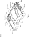
- FIG. 7 is a schematic cross-sectional view drawn along a division line 7-7 in FIG. 3 .
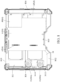
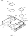
- FIG. 8 is a schematic diagram of a partial structure of an embodiment of an expansion component according to the present invention.
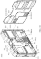
- FIG. 8 is a schematic diagram in which configurations inside an upper compartment 511 are exposed without displaying a top plate H11 in a first case H1.
- the electronic component A accommodated in the upper compartment 511 in the electronic device assembly and electrically connected to the first circuit board A1 is a bus apparatus A9 (for example, a PCI-E card, a PCI-E interface display card, a PCI-E interface SSD, or another PCI-E interface high-speed signal transmission apparatus).
- a bus apparatus A9 for example, a PCI-E card, a PCI-E interface display card, a PCI-E interface SSD, or another PCI-E interface high-speed signal transmission apparatus.
- the first heat dissipation module 30A includes the fan 31 that is accommodated in the upper compartment 511.
- the fan 31 is electrically connected to the first circuit board A1
- the fan 31 is provided with an air outlet 3112
- the air outlet 3112 of the fan 31 faces toward the bus apparatus A9 to dissipate heat for the bus apparatus A9.
- the first case H1 does not include the assembly groove H112.
- the first case H1 further includes a waterproof cover plate H17, where a shape and a size of the waterproof cover plate H17 corresponds to the shape and the size of the second opening H1112, and the waterproof cover plate H17 covers the second opening H1112, to close the second opening H1112, thereby ensuring waterproofness inside the first case H1.
- the second heat dissipation module 30B is arranged in the lower compartment S12 and can simultaneously dissipate heat for the electronic components A inside the upper compartment S11 and the lower compartment S12. In the embodiments, the electronic components A accommodated in the upper compartment 511 abut against the partition 10.
- the second heat dissipation module 30B includes the fan 31 and a diversion case 33.
- the diversion case 33 includes an input section 331 and an output section 332 that are connected. An angle is defined between an extending direction of the input section 331 and an extending direction of the output section 332, the diversion case 33 is accommodated in the lower compartment S12, and the output section 332 abuts against the partition 10 and one of the electronic components A located in the lower compartment S12.
- the fan 31 is arranged at a junction of the input section 331 and the output section 332.
- the input section 331 and the output section 332 of the diversion case 33 are connected to form an L-shape. That is, the angle between the extending direction of the input section 331 and the extending direction of the output section 332 is 90 degrees. Therefore, a position at which the second heat dissipation module 30B introduces the airflow and a position at which the airflow is led out for heat dissipation are not on a same straight line but can meet position configuration requirements of different electronic components A inside the lower compartment S12.
- the diversion case 33 includes a connecting section 333, where the connecting section 333 is located between the input section 331 and the output section 332, and the fan 31 is accommodated in the connecting section 333.
- an end of the input section 331 away from the connecting section 333 and an end of the output section 332 away from the connecting section are respectively inclined relative to the connecting section 333.
- depths may be configured for a part between the connecting section 333 and the input section 331 and a part between the output section 332 and the connecting section 333 for collecting and guiding an airflow, and the end of the input section 331 away from the connecting section 333 and the end of the output section 332 away from the connecting section may be close to an assembled position of the diversion case 33, to smoothly guide input and output of the airflow.
- the entire diversion case 33 includes an edge 334, where the edge 334 surrounds and forms an opening 3341, and the input section 331, the output section 332, and the connecting section 333 are located within a range of the opening 3341.
- the bottom plate H12 of the first case H1 of the expansion component E1 includes a plurality of through holes H121.
- the edge 334 of the diversion case 33 abuts against the bottom plate H12 of the first case H1, and the opening 3341 covers the through hole H121. Therefore, the airflow can be smoothly inputted into the diversion case 33 from the bottom plate H12 of the first case H1 and outputted from the diversion case 33, to ensure a diversion effect and a heat dissipation effect of the diversion case 33.
- the through holes H121 of the bottom plate H12 of the first case H1 include a plurality of first through holes H1211 and a plurality of second through holes H1212. Positions of the first through holes H1211 correspond to a position of the input section 331, and positions of the second through holes H1212 correspond to a position of the output section 332, to ensure smoothness of the airflow flowing in and out of the diversion case 33.
- the diversion case 33 includes an inner surface 335.
- the inner surface 335 faces toward the bottom plate H12, and the inner surface 335 has different depth configurations to be attached to different electronic components A, so as to dissipate heat for a plurality of electronic components A simultaneously.
- the output section 332 includes a first heat dissipation section 3321 and a second heat dissipation section 3322.
- the inner surface 335 has a first height L1 between the first heat dissipation section 3321 and the opening 3341, the inner surface 335 has a second height L2 between the second heat dissipation section 3322 and the opening 3341, and the first height L1 is different from the second height L2. Therefore, the diversion case 33 may be simultaneously in contact with the electronic components A located inside the lower compartment S12 and the upper compartment S11 through the first heat dissipation section 3321 and the second heat dissipation section 3322 and can simultaneously dissipate heat for the electronic components A located inside the upper compartment S11 and the lower compartment S12.
- the first height L1 is less than the second height L2, that is, a distance of the inner surface 335 between the first heat dissipation section 3321 and the opening 3341 is less than a distance of the inner surface 335 between the second heat dissipation section 3322 and the opening 3341, and the first heat dissipation section 3321 is closer to the bottom plate H12 than the second heat dissipation section 3322.
- the first heat dissipation section 3321 of the diversion case 33 abuts against the electronic component A located in the lower compartment S12
- the second heat dissipation section 3322 abuts against the partition 10
- a position of the second heat dissipation section 3322 corresponds to the position of the electronic component A located in the upper compartment 511.
- the bus apparatus A9 abuts against the partition 10
- the second heat dissipation section 3322 of the diversion case 33 abuts against a position at which the partition 10 corresponds to the bus apparatus A9 to dissipate heat for the bus apparatus A9.
- the electronic components A of the expansion component E1 further include a third circuit board A10, where the third circuit board A10 is arranged in the lower compartment S12 and is parallel to and spaced apart from the second circuit board A5, and the third circuit board A10 is closer to the bottom plate H12 than the second circuit board A5.
- the first heat dissipation section 3321 of the diversion case 33 abuts against the third circuit board A10 to dissipate heat for the third circuit board A10. Therefore, a plurality of overlapping electronic components A may be configured in the lower compartment S12 of the expansion component E1, and heat of the overlapping electronic components A can still be fully dissipated by the second heat dissipation module 30B, to ensure that the electronic components A can smoothly run, thereby ensuring an expansion function of the expansion component E1.
- the output section 332 of the diversion case 33 further includes a third heat dissipation section 3323, where the first heat dissipation section 3321, the second heat dissipation section 3322, and the third heat dissipation section 3323 of the output section 332 are sequentially connected, and the third heat dissipation section 3323 of the output section 332 is connected to the fan 31. Therefore, air enters from the input section 331 of the diversion case 33, then enters the fan 31, and then is discharged sequentially by the third heat dissipation section 3323, the second heat dissipation section 3322, and the first heat dissipation section 3321 of the output section 332.
- the heat of all the electronic components A abutting against the first heat dissipation section 3321, the second heat dissipation section 3322, and the third heat dissipation section 3323 can be dissipated by the diversion case 33.
- the inner surface 335 of the diversion case 33 has a third height L3 between the third heat dissipation section 3323 and the opening 3341, where the third height L3 is different from the first height L1 and the second height L2. Therefore, the electronic components A against which the first heat dissipation section 3321, the second heat dissipation section 3322, and the third heat dissipation section 3323 abut for heat dissipation may be respectively located at different height positions but can still be fully dissipated by the diversion case 33.
- the third heat dissipation section 3323 abuts against the second circuit board A5, but the present invention is not limited thereto.
- the fan 31 is a centrifugal fan and includes a case 311, where the case 311 is provided with an air inlet 3111 and an air outlet 3112 that are perpendicular to each other.
- the third heat dissipation section 3323 of the output section 332 of the diversion case 33 is flush with the air outlet 3112 of the fan 31. Therefore, an airflow outputted from the air outlet 3112 of the fan 31 can smoothly enter the output section 332 from the third heat dissipation section 3323, to improve smoothness of the airflow.
- the third height L3 is greater than the first height L1 and is less than the second height L2. Therefore, a large amount of air entering the output section 332 from the fan 31 can be collected at the second heat dissipation section 3322 after passing through the third heat dissipation section 3323, to obviously dissipate heat for the electronic component A at a position corresponding to the partition 10, and then is discharged by the first heat dissipation section 3321 closest to the bottom plate H12.
- the input section 331 of the diversion case 33 includes an inlet section 3311 and a collecting section 3312 that are sequentially connected, where the collecting section 3312 is connected between the inlet section 3311 and the connecting section 333 and is flush with the connecting section 333.
- the fan 31 is arranged in the connecting section 333 and the air inlet 3111 faces toward the inner surface 335, and a distance is provided between the air inlet 3111 of the fan 31 and the inner surface 335. Therefore, air can enter the fan 31 after being guided by the input section 331 of the diversion case 33 for the fan 31 to generate an active airflow.
- the inner surface 335 of the diversion case 33 also has the second height L2 from the opening 3341 at the position of the collecting section 3312 and the connecting section 333. Therefore, the collecting section 3312 can collect a large amount of air introduced by the inlet section 3311 into the fan 31, so as to improve a flow rate of air flowing through the diversion case 33 and the heat dissipation efficiency.
- the connecting section 333 also has the second height L2
- the connecting section 333 can also abut against the partition 10, to increase an area where the partition 10 abuts against the diversion case 33, thereby improving a support force of the partition 10 and also improving heat dissipation effect for the electronic components A abutting against the partition 10.
- the second heat dissipation module 30B further includes a plurality of heat dissipation fins 34, where the heat dissipation fins 34 are arranged in the diversion case 33.
- the plurality of heat dissipation fins 34 are respectively arranged in the first heat dissipation section 3321, the second heat dissipation section 3322, and the inlet section 3311 of the diversion case 33, and the heat dissipation fins 34 in the first heat dissipation section 3321, the second heat dissipation section 3322, and the inlet section 3311 are parallel to and spaced apart from each other. Therefore, a contact area between the air and the diversion case 33 is increased, to improve the heat dissipation effect.
- the inlet section 3311 of the input section 331 of the diversion case 33 has a first end 3313 and a second end 3314, where the second end 3314 is closer to the fan 31 than the first end 3313 and is connected to the fan 31, a height of the inner surface 335 from the second end 3314 to the opening 3341 is greater than a height of the inner surface from the first end 3313 to the opening 3341, and the first end 3313 is obliquely connected to the second end 3314, so that the inlet section 3311 is inclined to the bottom plate H12.
- the inlet section 3311 obliquely extends to the bottom plate H12, and air is introduced by the first through hole H1211 of the bottom plate H12, to improve the smoothness of the air entering the diversion case 33.
- the output section 332 of the diversion case 33 further includes an outlet section 3324, where the outlet section 3324 is connected to the first heat dissipation section 3321 and is inclined to the first heat dissipation section 3321, so that the outlet section 3324 obliquely extends to the bottom plate H12.
- the outlet section 3324 obliquely extends to the bottom plate H12, and air is introduced by the second through hole H1212 of the bottom plate H12, to improve the smoothness of the air entering the diversion case 33.
- the inner surface 335 of the diversion case 33 is inclined relative to the bottom plate H12 in an extending direction between the first heat dissipation section 3321 and the second heat dissipation section 3322. Therefore, it is ensured that the air in the second heat dissipation section 3322 farthest from the opening 3341 can smoothly flow to the first heat dissipation section 3321, to ensure the smoothness of the heat dissipation airflow.
Landscapes
- Engineering & Computer Science (AREA)
- Microelectronics & Electronic Packaging (AREA)
- Theoretical Computer Science (AREA)
- Physics & Mathematics (AREA)
- General Engineering & Computer Science (AREA)
- General Physics & Mathematics (AREA)
- Human Computer Interaction (AREA)
- Computer Hardware Design (AREA)
- Manufacturing & Machinery (AREA)
- Cooling Or The Like Of Electrical Apparatus (AREA)
- Casings For Electric Apparatus (AREA)
- Mounting Of Printed Circuit Boards And The Like (AREA)
- Ceramic Capacitors (AREA)
- Packaging Frangible Articles (AREA)
Priority Applications (1)
| Application Number | Priority Date | Filing Date | Title |
|---|---|---|---|
| EP26153177.6A EP4707995A3 (de) | 2022-02-11 | 2023-02-07 | Expansionskomponente |
Applications Claiming Priority (3)
| Application Number | Priority Date | Filing Date | Title |
|---|---|---|---|
| US202263309463P | 2022-02-11 | 2022-02-11 | |
| US202263351422P | 2022-06-12 | 2022-06-12 | |
| CN202211467197.0A CN116600520A (zh) | 2022-02-11 | 2022-11-22 | 电子装置组合及其扩充组件 |
Related Child Applications (2)
| Application Number | Title | Priority Date | Filing Date |
|---|---|---|---|
| EP26153177.6A Division EP4707995A3 (de) | 2022-02-11 | 2023-02-07 | Expansionskomponente |
| EP26153177.6A Division-Into EP4707995A3 (de) | 2022-02-11 | 2023-02-07 | Expansionskomponente |
Publications (3)
| Publication Number | Publication Date |
|---|---|
| EP4239446A2 true EP4239446A2 (de) | 2023-09-06 |
| EP4239446A3 EP4239446A3 (de) | 2023-11-22 |
| EP4239446B1 EP4239446B1 (de) | 2026-05-06 |
Family
ID=85175762
Family Applications (2)
| Application Number | Title | Priority Date | Filing Date |
|---|---|---|---|
| EP23155307.4A Active EP4239446B1 (de) | 2022-02-11 | 2023-02-07 | Elektronische vorrichtungsanordnung und erweiterungskomponente dafür |
| EP26153177.6A Pending EP4707995A3 (de) | 2022-02-11 | 2023-02-07 | Expansionskomponente |
Family Applications After (1)
| Application Number | Title | Priority Date | Filing Date |
|---|---|---|---|
| EP26153177.6A Pending EP4707995A3 (de) | 2022-02-11 | 2023-02-07 | Expansionskomponente |
Country Status (3)
| Country | Link |
|---|---|
| US (1) | US20230262896A1 (de) |
| EP (2) | EP4239446B1 (de) |
| AU (1) | AU2023200258B2 (de) |
Families Citing this family (1)
| Publication number | Priority date | Publication date | Assignee | Title |
|---|---|---|---|---|
| CN114706452B (zh) * | 2021-10-07 | 2024-06-21 | 神基投资控股股份有限公司 | 具有功能扩充机制的电脑以及免拆卸电脑的功能扩充方法 |
Citations (1)
| Publication number | Priority date | Publication date | Assignee | Title |
|---|---|---|---|---|
| US20130083254A1 (en) * | 2011-09-29 | 2013-04-04 | Kabushiki Kaisha Toshiba | Television and electronic apparatus |
Family Cites Families (4)
| Publication number | Priority date | Publication date | Assignee | Title |
|---|---|---|---|---|
| JP3581318B2 (ja) * | 2001-02-06 | 2004-10-27 | 株式会社東芝 | 電子機器システムおよび携帯形電子機器に用いる冷却装置 |
| CN106062660A (zh) * | 2014-02-20 | 2016-10-26 | 鲁斯特科有限责任公司 | 膝上型电脑冷却支架 |
| US10831248B2 (en) * | 2018-05-09 | 2020-11-10 | Adesa, Inc. | Mobile device temperature-regulating case |
| US10468812B1 (en) * | 2018-10-12 | 2019-11-05 | Getac Technology Corporation | Electrical connector structure and waterproof ring thereof |
-
2023
- 2023-01-18 AU AU2023200258A patent/AU2023200258B2/en active Active
- 2023-02-06 US US18/164,901 patent/US20230262896A1/en active Pending
- 2023-02-07 EP EP23155307.4A patent/EP4239446B1/de active Active
- 2023-02-07 EP EP26153177.6A patent/EP4707995A3/de active Pending
Patent Citations (1)
| Publication number | Priority date | Publication date | Assignee | Title |
|---|---|---|---|---|
| US20130083254A1 (en) * | 2011-09-29 | 2013-04-04 | Kabushiki Kaisha Toshiba | Television and electronic apparatus |
Also Published As
| Publication number | Publication date |
|---|---|
| US20230262896A1 (en) | 2023-08-17 |
| EP4707995A3 (de) | 2026-04-08 |
| EP4239446B1 (de) | 2026-05-06 |
| EP4239446A3 (de) | 2023-11-22 |
| AU2023200258A1 (en) | 2023-08-31 |
| EP4707995A2 (de) | 2026-03-11 |
| AU2023200258B2 (en) | 2024-07-11 |
Similar Documents
| Publication | Publication Date | Title |
|---|---|---|
| US20070081308A1 (en) | Computer system | |
| US6512672B1 (en) | Modular air flow distribution system | |
| US6970346B2 (en) | Redundant power supply wirelessly connected to motherboard | |
| US20120327589A1 (en) | Computer system with airflow guiding duct | |
| EP4239446A2 (de) | Elektronische vorrichtungsanordnung und erweiterungskomponente dafür | |
| CN110568910A (zh) | 车用主机及车用计算机系统 | |
| AU2023200259B2 (en) | Electronic device assembly, expansion component thereof, and heat dissipation module | |
| EP0838749B1 (de) | Informationsverarbeitungsgerät von dünner Struktur | |
| EP4510800A1 (de) | Elektronische vorrichtung | |
| TWI821040B (zh) | 電子裝置組合及其擴充組件 | |
| CN116600521B (zh) | 电子装置组合及其扩充组件及散热模块 | |
| CN116600521A (zh) | 电子装置组合及其扩充组件及散热模块 | |
| CN211351066U (zh) | 连接器及通信设备 | |
| WO2013176488A1 (ko) | 키보드 일체형 컴퓨터 본체 | |
| CN214376276U (zh) | 用于服务器机箱的散热装置及服务器机箱 | |
| EP4510797A1 (de) | Elektronische vorrichtung | |
| CN215006481U (zh) | 一种含风扇的散热机箱结构 | |
| TWI917163B (zh) | 獨立顯示卡散熱機箱 | |
| CN223871034U (zh) | 具有散热功能的PCIe装置 | |
| JP2009104665A (ja) | 薄型構造の情報処理装置 | |
| CN223582411U (zh) | 硬盘系统及其硬盘框架 | |
| CN222319750U (zh) | 储存阵列装置及具有此储存阵列装置的服务器设备 | |
| CN222053697U (zh) | 一种电子设备 | |
| CN223108324U (zh) | 机箱、板卡集成组件、量子计算测控系统及量子计算机 | |
| TWI725669B (zh) | 適配冗餘電源模組的電源供應器外殼 |
Legal Events
| Date | Code | Title | Description |
|---|---|---|---|
| PUAI | Public reference made under article 153(3) epc to a published international application that has entered the european phase |
Free format text: ORIGINAL CODE: 0009012 |
|
| STAA | Information on the status of an ep patent application or granted ep patent |
Free format text: STATUS: THE APPLICATION HAS BEEN PUBLISHED |
|
| AK | Designated contracting states |
Kind code of ref document: A2 Designated state(s): AL AT BE BG CH CY CZ DE DK EE ES FI FR GB GR HR HU IE IS IT LI LT LU LV MC ME MK MT NL NO PL PT RO RS SE SI SK SM TR |
|
| PUAL | Search report despatched |
Free format text: ORIGINAL CODE: 0009013 |
|
| AK | Designated contracting states |
Kind code of ref document: A3 Designated state(s): AL AT BE BG CH CY CZ DE DK EE ES FI FR GB GR HR HU IE IS IT LI LT LU LV MC ME MK MT NL NO PL PT RO RS SE SI SK SM TR |
|
| RIC1 | Information provided on ipc code assigned before grant |
Ipc: G06F 1/20 20060101ALI20231013BHEP Ipc: G06F 1/16 20060101AFI20231013BHEP |
|
| STAA | Information on the status of an ep patent application or granted ep patent |
Free format text: STATUS: REQUEST FOR EXAMINATION WAS MADE |
|
| 17P | Request for examination filed |
Effective date: 20240123 |
|
| RBV | Designated contracting states (corrected) |
Designated state(s): AL AT BE BG CH CY CZ DE DK EE ES FI FR GB GR HR HU IE IS IT LI LT LU LV MC ME MK MT NL NO PL PT RO RS SE SI SK SM TR |
|
| STAA | Information on the status of an ep patent application or granted ep patent |
Free format text: STATUS: EXAMINATION IS IN PROGRESS |
|
| 17Q | First examination report despatched |
Effective date: 20250711 |
|
| GRAP | Despatch of communication of intention to grant a patent |
Free format text: ORIGINAL CODE: EPIDOSNIGR1 |
|
| STAA | Information on the status of an ep patent application or granted ep patent |
Free format text: STATUS: GRANT OF PATENT IS INTENDED |
|
| INTG | Intention to grant announced |
Effective date: 20251126 |
|
| GRAS | Grant fee paid |
Free format text: ORIGINAL CODE: EPIDOSNIGR3 |
|
| GRAA | (expected) grant |
Free format text: ORIGINAL CODE: 0009210 |
|
| STAA | Information on the status of an ep patent application or granted ep patent |
Free format text: STATUS: THE PATENT HAS BEEN GRANTED |