EP4239347B1 - Battery diagnosing system and method - Google Patents
Battery diagnosing system and method Download PDFInfo
- Publication number
- EP4239347B1 EP4239347B1 EP22864982.8A EP22864982A EP4239347B1 EP 4239347 B1 EP4239347 B1 EP 4239347B1 EP 22864982 A EP22864982 A EP 22864982A EP 4239347 B1 EP4239347 B1 EP 4239347B1
- Authority
- EP
- European Patent Office
- Prior art keywords
- battery
- diagnosis result
- server
- current state
- diagnosis
- Prior art date
- Legal status (The legal status is an assumption and is not a legal conclusion. Google has not performed a legal analysis and makes no representation as to the accuracy of the status listed.)
- Active
Links
Images


Classifications
-
- G—PHYSICS
- G01—MEASURING; TESTING
- G01R—MEASURING ELECTRIC VARIABLES; MEASURING MAGNETIC VARIABLES
- G01R31/00—Arrangements for testing electric properties; Arrangements for locating electric faults; Arrangements for electrical testing characterised by what is being tested not provided for elsewhere
- G01R31/36—Arrangements for testing, measuring or monitoring the electrical condition of accumulators or electric batteries, e.g. capacity or state of charge [SoC]
- G01R31/371—Arrangements for testing, measuring or monitoring the electrical condition of accumulators or electric batteries, e.g. capacity or state of charge [SoC] with remote indication, e.g. on external chargers
-
- G—PHYSICS
- G01—MEASURING; TESTING
- G01R—MEASURING ELECTRIC VARIABLES; MEASURING MAGNETIC VARIABLES
- G01R31/00—Arrangements for testing electric properties; Arrangements for locating electric faults; Arrangements for electrical testing characterised by what is being tested not provided for elsewhere
- G01R31/36—Arrangements for testing, measuring or monitoring the electrical condition of accumulators or electric batteries, e.g. capacity or state of charge [SoC]
- G01R31/392—Determining battery ageing or deterioration, e.g. state of health
-
- G—PHYSICS
- G01—MEASURING; TESTING
- G01R—MEASURING ELECTRIC VARIABLES; MEASURING MAGNETIC VARIABLES
- G01R31/00—Arrangements for testing electric properties; Arrangements for locating electric faults; Arrangements for electrical testing characterised by what is being tested not provided for elsewhere
- G01R31/36—Arrangements for testing, measuring or monitoring the electrical condition of accumulators or electric batteries, e.g. capacity or state of charge [SoC]
- G01R31/396—Acquisition or processing of data for testing or for monitoring individual cells or groups of cells within a battery
-
- G—PHYSICS
- G01—MEASURING; TESTING
- G01R—MEASURING ELECTRIC VARIABLES; MEASURING MAGNETIC VARIABLES
- G01R31/00—Arrangements for testing electric properties; Arrangements for locating electric faults; Arrangements for electrical testing characterised by what is being tested not provided for elsewhere
- G01R31/36—Arrangements for testing, measuring or monitoring the electrical condition of accumulators or electric batteries, e.g. capacity or state of charge [SoC]
- G01R31/367—Software therefor, e.g. for battery testing using modelling or look-up tables
-
- G—PHYSICS
- G01—MEASURING; TESTING
- G01R—MEASURING ELECTRIC VARIABLES; MEASURING MAGNETIC VARIABLES
- G01R31/00—Arrangements for testing electric properties; Arrangements for locating electric faults; Arrangements for electrical testing characterised by what is being tested not provided for elsewhere
- G01R31/36—Arrangements for testing, measuring or monitoring the electrical condition of accumulators or electric batteries, e.g. capacity or state of charge [SoC]
- G01R31/382—Arrangements for monitoring battery or accumulator variables, e.g. SoC
- G01R31/3842—Arrangements for monitoring battery or accumulator variables, e.g. SoC combining voltage and current measurements
-
- G—PHYSICS
- G08—SIGNALLING
- G08B—SIGNALLING OR CALLING SYSTEMS; ORDER TELEGRAPHS; ALARM SYSTEMS
- G08B17/00—Fire alarms; Alarms responsive to explosion
- G08B17/06—Electric actuation of the alarm, e.g. using a thermally-operated switch
-
- Y—GENERAL TAGGING OF NEW TECHNOLOGICAL DEVELOPMENTS; GENERAL TAGGING OF CROSS-SECTIONAL TECHNOLOGIES SPANNING OVER SEVERAL SECTIONS OF THE IPC; TECHNICAL SUBJECTS COVERED BY FORMER USPC CROSS-REFERENCE ART COLLECTIONS [XRACs] AND DIGESTS
- Y02—TECHNOLOGIES OR APPLICATIONS FOR MITIGATION OR ADAPTATION AGAINST CLIMATE CHANGE
- Y02E—REDUCTION OF GREENHOUSE GAS [GHG] EMISSIONS, RELATED TO ENERGY GENERATION, TRANSMISSION OR DISTRIBUTION
- Y02E60/00—Enabling technologies; Technologies with a potential or indirect contribution to GHG emissions mitigation
- Y02E60/10—Energy storage using batteries
Definitions
- the present disclosure relates to a battery diagnosing system and method, and more particularly, to a battery diagnosing system and method for determining a current state of a battery based on a diagnosis result in a battery management system (BMS) and a server.
- BMS battery management system
- Batteries commercially available at present include nickel-cadmium batteries, nickel hydrogen batteries, nickel-zinc batteries, lithium batteries and the like.
- the lithium batteries are in the limelight since they have almost no memory effect compared to nickel-based batteries and also have very low self-charging rate and high energy density.
- Temperature, voltage, and current are representative examples of battery information capable of diagnosing the state of the battery, and the state of the battery may be diagnosed based on the battery information. It is desirable to periodically diagnose the state of the battery because it is possible to judge whether the battery is abnormal or estimate the lifespan of the battery through the battery state diagnosis.
- KR 2019 0125906 A , KR 102 259 643 B1 , US 2018/143257 A1 , US 2003/184307 A1 and WO 2021/040236 A1 respectively disclose battery diagnosing systems provided separately from corresponding battery management systems
- US 2020/271725 A1 discloses a battery diagnosing system comprising a battery management system.
- the present disclosure is designed to solve the problems of the related art, and therefore the present disclosure is directed to providing a battery diagnosing system and method, which may determine a current state of a battery based on a plurality of diagnosis results in a BMS and a server, and properly control the battery based on the determined current state.
- a battery diagnosing system may comprise: a BMS configured to obtain battery information including at least one of temperature, current and voltage of a battery and generate a first diagnosis result corresponding to a current state of the battery based on the battery information; and a server configured to receive the battery information and the first diagnosis result from the BMS, generate a second diagnosis result corresponding to the current state of the battery and a third diagnosis result corresponding to a future state of the battery from the battery information based on a pre-trained state estimation model, and determine the current state of the battery based on a plurality of diagnosis results for the first diagnosis result, the second diagnosis result and the third diagnosis result.
- the diagnosis results may be configured to be classified into a first level, a second level, and a third level in order of risk for the battery.
- the server may be configured to determine the current state according to a comparison result for the plurality of diagnosis results based on a preset battery state determination rule.
- the server may be configured to judge whether the plurality of diagnosis results are the same and determine the current state of the battery based on the judgment result and the battery state determination rule.
- the server may be configured to determine the current state of the battery to correspond to any one of the plurality of diagnosis results.
- the server may be configured to re-receive the first diagnosis result from the BMS for a predetermined time and determine the current state of the battery based on the re-received first diagnosis result, the second diagnosis result and the third diagnosis result.
- the server may be configured to determine the level with a highest risk among the re-received first diagnosis result, the second diagnosis result and the third diagnosis result as the current state of the battery.
- the server may be configured to determine the level with a highest risk among the plurality of diagnosis results as the current state of the battery.
- the server may be configured to retrain the state estimation model based on the battery information received from the BMS and accumulatively stored, regenerate the second diagnosis result and the third diagnosis result for the battery using the retrained state estimation model, and diagnose the current state of the battery based on the first diagnosis result, the regenerated second diagnosis result and the regenerated third diagnosis result.
- the server may be configured not to determine the current state of the battery and to output a notification that an error occurs in the state estimation model.
- the server may be configured to retrain the state estimation model.
- the server may be configured to determine a diagnostic measure for the battery to correspond to the determined current state of the battery and transmit the determined diagnostic measure to the BMS.
- the BMS may be configured to control the battery according to the diagnostic measure received from the server.
- the server may be configured to determine a fire occurrence level as the state current state of the battery based on the plurality of diagnosis results and determine any one of current blocking of the battery, cooling operation for the battery, and fire suppression for the battery as a diagnostic measure corresponding to the determined fire occurrence level.
- a battery diagnosing method may comprise: a battery information obtaining step of, by a BMS, obtaining battery information including at least one of temperature, current and voltage of a battery; a first diagnosis result generating step of, by the BMS, generating a first diagnosis result corresponding to a current state of the battery based on the battery information; a second and third diagnosis result generating step of, by a server, receiving the battery information and the first diagnosis result from the BMS and generating a second diagnosis result corresponding to the current state of the battery and a third diagnosis result corresponding to a future state of the battery from the battery information based on a pre-trained state estimation model; and a battery current state determining step of, by the server, determining the current state of the battery based on a plurality of diagnosis results for the first diagnosis result, the second diagnosis result and the third diagnosis result.
- a server may comprise: a communication unit; and a processor configured to receive battery information including at least one of temperature, current and voltage of a battery and a first diagnosis result corresponding to a current state of the battery generated based on the battery information from the BMS through the communication unit, generate a second diagnosis result corresponding to the current state of the battery and a third diagnosis result corresponding to a future state of the battery from the battery information based on a pre-trained state estimation model, and determine the current state of the battery based on the first diagnosis result, the second diagnosis result and the third diagnosis result.
- the current state of the battery can be determined with higher accuracy and reliability based on the diagnosis result for the battery generated by the BMS and the server.
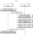
- FIG. 1 is a diagram schematically showing a battery diagnosing system according to an embodiment of the present disclosure.
- FIG. 2 is a diagram schematically showing an operational configuration of the battery diagnosing system according to an embodiment of the present disclosure.
- a battery diagnosing system 100 may include a battery management system (BMS) 110 and a server 120.
- BMS battery management system
- the BMS 110 refers to a battery management system capable of controlling a battery based on battery information (e.g., temperature, voltage, and current). Since the BMS 110 is a configuration commonly used in battery-related fields, a detailed description of the BMS 110 itself is omitted.
- battery information e.g., temperature, voltage, and current
- the BMS 110 may be configured to obtain battery information including at least one of temperature, current and voltage of the battery.
- the battery means one physically separable independent cell including a negative electrode terminal and a positive electrode terminal.
- one lithium-ion battery or lithium polymer battery may be regarded as a battery.
- the battery may refer to a battery module in which a plurality of cells are connected in series and/or in parallel.
- the battery will be described as meaning one independent cell.
- the BMS 110 may be configured to generate a first diagnosis result corresponding to a current state of the battery based on the battery information.
- the BMS 110 may generate a first diagnosis result for the battery according to a risk predetermined based on the battery information.
- the diagnosis result may be configured to be classified into a first level, a second level, and a third level in order of risk for the battery.
- the risk may be set such that the first level is lowest and the third level is highest.
- the BMS 110 may have a diagnosis algorithm capable of outputting a first diagnosis result corresponding to the current state of the battery from the battery information.
- the BMS 110 may generate a first diagnosis result corresponding to the current state of the battery by inputting the battery information to the diagnosis algorithm.
- the diagnosis algorithm may be provided to correspond to the storage capacity and performance of the BMS 110.
- the diagnostic algorithm may include a training model based on machine learning and/or a relational expression mapped to indicate a corresponding relationship between the battery information and the current state of the battery.
- the server 120 may be configured to receive the battery information and the first diagnosis result from the BMS 110.
- the server 120 and the BMS 110 may be connected to enable communication.
- the BMS 110 may transmit the obtained battery information and the generated first diagnosis result to the server 120, and the server 120 may receive the battery information and the first diagnosis result.
- the server 120 may include a communication unit.
- the communication unit may communicate with the BMS 110 through a wireless communication method such as Wi-Fi, WFD (Wi-Fi Direct), UWB (Ultra Wideband), or mobile communication.
- the communication unit may communicate with the BMS 110 through a wired communication method such as a wired LAN (Local Area Network).
- the server 120 may be configured to generate a second diagnosis result corresponding to the current state of the battery and a third diagnosis result corresponding to a future state of the battery from the battery information based on a pre-trained state estimation model.
- the state estimation model may be a machine learning-based training model configured to estimate and output a diagnosis result corresponding to the current state and the future state of the battery from the battery information.
- the state estimation model provided in the server 120 may be an XGB (eXtreme Gradient Boosting) model.
- the server 120 may include a memory for storing the state estimation model.
- the server 120 may accumulatively store the battery information previously received from the BMS 110 and train the state estimation model using the accumulatively stored battery information.
- the server 120 may further receive battery information for training from the outside or receive battery information from another BMS to train the state estimation model in consideration of all the received battery information. That is, the server 120 may train the state estimation model to output a diagnosis result corresponding to the current state and the future state of the battery from the input battery information by using at least one of the battery information previously received from the BMS 110, the battery information for training received from the outside, and the battery information received from another BMS.
- the state estimation model may not only output a second diagnosis result corresponding to the current state of the battery, but also estimate and output a third diagnosis result corresponding to the future state of the battery. That is, the state estimation model may be configured not only to estimate the current state of the battery but also to predict the future state of the battery.
- the second diagnosis result and the third diagnosis result may be determined according to a risk predetermined based on the battery information, like the first diagnosis result.
- the second diagnosis result and the third diagnosis result may be determined as a first level, a second level, or a third level according to risk.
- the method of outputting different results (the first diagnosis result corresponding to the current state and the second diagnosis result corresponding to the future state) for the same input (battery information) may be derived by differently setting types or weights of parameters considered according to the trained contents, so it should be noted that specific details of how one state estimation model can output different results (the second diagnosis result and the third diagnosis result) will be omitted.
- the server 120 may respectively store a first state estimation model that outputs a diagnosis result corresponding to the current state of the battery based on the input battery information and a second state estimation model that outputs a diagnosis result corresponding to the future state of the battery based on the input battery information.
- the server 120 may be configured to determine the current state of the battery based on a plurality of diagnosis results for the first diagnosis result, the second diagnosis result, and the third diagnosis result.
- the server 120 may determine the current state of the battery by considering both the first diagnosis result generated by the BMS 110 and the second diagnosis result and third diagnosis result directly generated.
- the server 120 may process a large amount of information compared to the BMS 110. Therefore, the BMS 110 may quickly determine the state of the battery based on real-time battery information, and the server 120 may accurately determine the state of the battery based on the accumulated battery information. In addition, in a general case, since the state of the battery determined by the server 120 is considered to be more accurate than the state of the battery determined by the BMS 110, the server 120 may be regarded as having complementary and supplementary characteristics to the BMS 110.
- the current state of the battery may be determined considering not only the second diagnosis result and the third diagnosis result directly generated by the server 120 but also the first diagnosis result generated by the BMS 110.
- the server 120 determines the current state of the battery by considering not only the first diagnosis result and the second diagnosis result corresponding to the current state of the battery but also the third diagnosis result corresponding to the future state of the battery predicted from the battery information, the possibility of erroneous diagnosis of the state of the battery may be effectively reduced by more conservatively determining the current state of the battery.
- the battery diagnosing system 100 has an advantage of more accurately and reliably determining the current state of the battery based on the diagnosis result of the battery generated by the BMS 110 and the server 120.
- the server 120 may be configured to determine a diagnostic measure for the battery to correspond to the determined current state of the battery.
- the diagnostic measure may be a preset battery control measure to correspond to the current state of the battery, that is, the risk to the battery.
- the diagnostic measure may include at least one of a current blocking measure, a cooling measure, and a fire suppression measure.
- the server 120 may be configured to transmit the determined diagnostic measure to the BMS 110.
- the BMS 110 may be configured to control the battery according to the diagnostic measure received from the server 120.
- the battery diagnosing system 100 determines a fire level of the battery and performs diagnosis on the determined fire level.
- the server 120 may determine a fire occurrence level based on a plurality of diagnosis results. That is, the server 120 may determine the fire occurrence level of the battery based on the first diagnosis result received from the BMS 110 and the second diagnosis result and the third diagnosis result directly generated.
- the fire occurrence level may include a first level corresponding to a normal state, a second level in which the temperature and/or pressure of the battery is increased to a first criterion, a third level in which the temperature and/or pressure of the battery is increased to a second criterion so that a fire is likely to occur, and a fourth level where a fire occurs in the battery.
- the server 120 may be configured to determine any one of battery state maintenance, current blocking of the battery, cooling operation of the battery, and fire suppression of the battery as a diagnostic measure corresponding to the determined fire occurrence level.
- the server 120 may determine the battery state maintenance as a diagnostic measure. In this case, the battery may not be separately controlled.
- the server 120 may determine the current blocking of the battery as a diagnostic measure. In this case, although the temperature and/or pressure of the battery is increased to the first criterion, the possibility of a fire is low, so the amount of current flowing into or discharged from the battery may be limited.
- the server 120 may determine the cooling operation of the battery as a diagnostic measure. In this case, since the temperature and/or pressure of the battery rises to the second criterion and the possibility of fire in the battery increases, a cooling measure for the battery may be performed to lower the temperature of the battery.
- the server 120 may determine fire suppression for the battery as a diagnostic measure.
- a measure for fire suppression may be performed.
- the fire suppression may be a measure of injecting carbon dioxide or fire extinguisher powder toward the battery.
- the server 120 may transmit the diagnostic measure corresponding to the fire occurrence level of the battery to the BMS 110, and the BMS 110 may control the battery to correspond to the received diagnostic measure, thereby performing an appropriate control measure to correspond to the current state of the battery.
- the battery diagnosing system 100 may maintain the battery in a safe state at all times by performing an appropriate diagnostic measure corresponding to the current state of the battery determined based on the plurality of diagnosis results.
- the battery diagnosing system 100 may perform immediate fire suppression even when a fire occurs in the battery, it is possible to prevent a larger accident caused by the fire.
- the processor may be, for example, a central processing unit (CPU), a micro controller unit (MCU), a digital signal processor (DSP), or a field programmable gate array (FPGA).
- CPU central processing unit
- MCU micro controller unit
- DSP digital signal processor
- FPGA field programmable gate array
- the server 120 determines the current state of the battery based on the first to third diagnosis results.
- the server 120 may be configured to determine the current state according to a comparison result for a plurality of diagnosis results based on a preset battery state determination rule.
- the server 120 may be configured to judge whether the plurality of diagnosis results are the same and determine the current state of the battery based on the judgment result and the battery state determination rule.
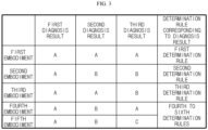
- FIG. 3 is a diagram for schematically explaining a determination rule corresponding to a diagnosis result according to various embodiments of the present disclosure.
- FIG. 4 is a diagram for schematically explaining various determination rules of the present disclosure.
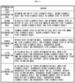
- the server 120 may be configured to determine the current state of the battery to correspond to any one of the plurality of diagnosis results.
- the first to third diagnosis results may all be the same as A.
- the server 120 may determine the current state of the battery according to the first determination rule.
- the server 120 may determine A as the current state of the battery. That is, referring to FIG. 4 , since the first determination rule is to determine any one of the first diagnosis result, the second diagnosis result and the third diagnosis result as the current state of the battery, when the plurality of diagnosis results are all the same, the server 120 may determine the current state of the battery to correspond to any one diagnosis result.
- the server 120 may be configured to re-receive the first diagnosis result from the BMS 110 for a predetermined time and determine the current state of the battery based on the re-received first diagnosis result, the second diagnosis result, and the third diagnosis result.
- the server 120 may be configured to determine the level with a highest risk among the re-received first diagnosis result, the second diagnosis result, and the third diagnosis result as the current state of the battery.
- the first diagnosis result may be A
- the second diagnosis result and the third diagnosis result may be B
- the server 120 may determine the current state of the battery according to the second determination rule.
- the server 120 may re-receive the first diagnosis result from the BMS 110, and determine the current state of the battery again based on the re-received first diagnosis result, the previously generated second diagnosis result and the third diagnosis result.
- the server 120 may be configured to determine the level with a highest risk among the plurality of diagnosis results as the current state of the battery.
- the server 120 may be configured to retrain the state estimation model based on the accumulatively stored battery information, regenerate the second diagnosis result and the third diagnosis result for the battery by using the retrained state estimation model, and diagnose the current state of the battery based on the first diagnosis result, the regenerated second diagnosis result, and the regenerated third diagnosis result.
- the first diagnosis result and the third diagnosis result may be A
- the second diagnosis result may be B
- the server 120 may determine the current state of the battery according to the fourth to sixth determination rules.
- the server 120 may retrain the state estimation model and regenerate a second diagnosis result and a third diagnosis result by using the retrained state estimation model.
- the server 120 may diagnose the current state of the battery again according to the first diagnosis result received from the BMS 110, the regenerated second diagnosis result, and the third diagnosis result.
- the server 120 may be configured to retrain the state estimation model based on the accumulatively stored battery information, regenerate the second diagnosis result and the third diagnosis result for the battery by using the retrained state estimation model, and diagnose the current state of the battery based on the first diagnosis result, the regenerated second diagnosis result and the regenerated third diagnosis result.
- the first diagnosis result may be A
- the second diagnosis result may be B
- the third diagnosis result may be C.
- the server 120 may determine the current state of the battery according to the fourth to sixth determination rules.
- the server 120 may retrain the state estimation model and regenerate the second diagnosis result and the third diagnosis result by using the retrained state estimation model.
- the server 120 may diagnose the current state of the battery again according to the first diagnosis result received from the BMS 110, the regenerated second diagnosis result, and the third diagnosis result.
- the server 120 may determine the current state of the battery according to the fourth to sixth determination rules.
- the server 120 may retrain the state estimation model based on the accumulatively stored battery information, and regenerate the second diagnosis result and the third diagnosis result based on the retrained state estimation model.
- the server 120 may determine the current state of the battery by applying the first to third determination rules to the first diagnosis result, the regenerated second diagnosis result, and the regenerated third diagnosis result. For example, if the first diagnosis result, the regenerated second diagnosis result, and the regenerated third diagnosis result correspond to the first to third embodiments of FIG. 3 , the server 120 may determine the current state of the battery according to the first to third determination rules.
- the server 120 may output a notification without determining the current state of the battery according to the fifth determination rule. That is, when the first diagnosis result and the regenerated third diagnosis result are the same and the regenerated second diagnosis result and the regenerated third diagnosis result are different, the server 120 may be configured to output a notification for an error of the state estimation model without determining the current state of the battery according to the fifth determination rule.
- the server 120 may determine the current state of the battery according to the sixth determination rule. That is, when the first diagnosis result, the regenerated second diagnosis result, and the regenerated third diagnosis result are all different, the server 120 may retrain the state estimation model according to the sixth determination rule. In addition, the server 120 may regenerate the second diagnosis result and the third diagnosis result based on the retrained state estimation model. The server 120 may determine the current state of the battery based on the first diagnosis result, the regenerated second diagnosis result, and the regenerated third diagnosis result. Here, the server 120 may determine an embodiment corresponding to the first diagnosis result, the regenerated second diagnosis result, and the regenerated third diagnosis result among the first to fifth embodiments of FIG. 3 and determine the current state of the battery according to the determined embodiment.
- the BMS 110 according to the present disclosure may be provided in a battery pack. That is, the battery pack according to the present disclosure may include the aforementioned BMS 110 and one or more battery cells. In addition, the battery pack may further include electrical components (relays, fuses, etc.) and a case.
- FIG. 5 is a diagram showing an exemplary configuration of a battery pack that may include the BMS 110 according to an embodiment of the present disclosure.
- the positive electrode terminal of the battery B may be connected to a positive electrode terminal P+ of the battery pack 1, and the negative electrode terminal of the battery B may be connected to a negative electrode terminal P- of the battery pack 1.
- the measuring unit 111 may be connected to a first sensing line SL1, a second sensing line SL2, a third sensing line SL3, and a fourth sensing line SL4.
- the measuring unit 111 may be connected to the positive electrode terminal of the battery B through the first sensing line SL1 and connected to the negative electrode terminal of the battery B through the second sensing line SL2.
- the measuring unit 111 may measure the voltage of the battery B based on the voltages respectively measured at the first sensing line SL1 and the second sensing line SL2.
- the measuring unit 111 may be connected to a current measuring unit A through the third sensing line SL3.
- the current measuring unit A may be an ampere meter or a shunt resistor capable of measuring a charging current and a discharging current of the battery B.
- the measuring unit 111 may calculate a charge amount by measuring the charging current of the battery B through the third sensing line SL3.
- the measuring unit 111 may calculate a discharge amount by measuring the discharge current of the battery B through the third sensing line SL3.
- the measuring unit 111 may measure the temperature of the battery B through the fourth sensing line SL4.
- the voltage, current, and temperature of the battery B measured by the measuring unit 111 may be transmitted to a control unit 112 and a storage unit 113.
- control unit provided to the BMS 110 may selectively include processors known in the art, application-specific integrated circuit (ASIC), other chipsets, logic circuits, registers, communication modems, data processing devices, and the like to execute various control logic performed in the present disclosure.
- ASIC application-specific integrated circuit
- the control unit may be implemented as a set of program modules.
- the program module may be stored in a memory and executed by the control unit.
- the memory may be located inside or out of the control unit and may be connected to the control unit by various well-known means.
- each step of the battery diagnosing method may be performed by the battery management apparatus 100.
- the battery management apparatus 100 Preferably, each step of the battery diagnosing method may be performed by the battery management apparatus 100.
- contents overlapping with the previously described contents will be omitted or briefly described.
- the battery diagnosing method may include a battery information obtaining step, a first diagnosis result generating step, a second and third diagnosis result generating step, and a battery current state determining step.
- the battery information obtaining step is a step of obtaining battery information including at least one of temperature, current, and voltage of a battery, and may be performed by the BMS 110.
- the first diagnosis result generating step is a step of generating a first diagnosis result corresponding to a current state of the battery based on the battery information, and may be performed by the BMS 110.
- the BMS 110 may generate a first diagnosis result corresponding to the current state of the battery by inputting the battery information to a provided diagnosis algorithm.
- the second and third diagnosis result generating step is a step of receiving the battery information and the first diagnosis result from the BMS 110 and generating a second diagnosis result corresponding to the current state of the battery and a third diagnosis result corresponding to a future state of the battery from the battery information based on a pre-trained state estimation model, and may be performed by the server 120.
- the battery current state determining step is a step of determining the current state of the battery based on a plurality of diagnosis results for the first diagnosis result, the second diagnosis result, and the third diagnosis result, and may be performed by the server 120.
- the server 120 may determine the current state of the battery based on a determination rule corresponding to the first diagnosis result, the second diagnosis result, and the third diagnosis result.
- the battery diagnosing method may further include a diagnostic measure determining step (S500) and a battery controlling step (S600).
- the diagnostic measure determining step (S500) is a step of determining a diagnostic measure for the battery to correspond to the determined current state of the battery, and may be performed by the server 120.
- a plurality of diagnostic measures may be set according to the risk of the battery, and the server 120 may determine a diagnostic measure corresponding to the current state of the battery.
- the diagnostic measure may include at least one of a current blocking measure, a cooling measure, and a fire suppression measure.
- the battery controlling step (S600) is a step of controlling the battery according to the diagnostic measure determined in the diagnostic measure determining step (S500), and may be performed by the BMS 110.
- the BMS 110 may receive the determined diagnostic measure from the server 120.
- the BMS 110 may control the battery according to the diagnostic measure determined by the server 120.
- the BMS 110 may maintain the state of the battery or block the current of the battery according to the current state of the battery.
- the BMS 110 may perform a cooling measure or a fire suppression measure according to the current state of the battery.
- the battery since an appropriate diagnostic measure corresponding to the current state of the battery determined based on a plurality of diagnosis results is performed, the battery may always be maintained in a safe state. In addition, even if a fire occurs in the battery, immediate fire suppression may be performed, so it is possible to prevent a larger accident from occurring due to the fire.
- the embodiments of the present disclosure described above may not be implemented only through an apparatus and a method, but may be implemented through a program that realizes a function corresponding to the configuration of the embodiments of the present disclosure or a recording medium on which the program is recorded.
- the program or recording medium may be easily implemented by those skilled in the art from the above description of the embodiments.
Landscapes
- Physics & Mathematics (AREA)
- General Physics & Mathematics (AREA)
- Secondary Cells (AREA)
- Business, Economics & Management (AREA)
- Emergency Management (AREA)
- Tests Of Electric Status Of Batteries (AREA)
- Charge And Discharge Circuits For Batteries Or The Like (AREA)
Priority Applications (1)
| Application Number | Priority Date | Filing Date | Title |
|---|---|---|---|
| EP25157939.7A EP4531015A3 (en) | 2021-08-31 | 2022-08-29 | Battery diagnosing system and method |
Applications Claiming Priority (2)
| Application Number | Priority Date | Filing Date | Title |
|---|---|---|---|
| KR1020210115865A KR102710934B1 (ko) | 2021-08-31 | 2021-08-31 | 배터리 진단 시스템 및 방법 |
| PCT/KR2022/012882 WO2023033480A1 (ko) | 2021-08-31 | 2022-08-29 | 배터리 진단 시스템 및 방법 |
Related Child Applications (2)
| Application Number | Title | Priority Date | Filing Date |
|---|---|---|---|
| EP25157939.7A Division-Into EP4531015A3 (en) | 2021-08-31 | 2022-08-29 | Battery diagnosing system and method |
| EP25157939.7A Division EP4531015A3 (en) | 2021-08-31 | 2022-08-29 | Battery diagnosing system and method |
Publications (3)
| Publication Number | Publication Date |
|---|---|
| EP4239347A1 EP4239347A1 (en) | 2023-09-06 |
| EP4239347A4 EP4239347A4 (en) | 2024-06-05 |
| EP4239347B1 true EP4239347B1 (en) | 2025-04-23 |
Family
ID=85412884
Family Applications (2)
| Application Number | Title | Priority Date | Filing Date |
|---|---|---|---|
| EP22864982.8A Active EP4239347B1 (en) | 2021-08-31 | 2022-08-29 | Battery diagnosing system and method |
| EP25157939.7A Pending EP4531015A3 (en) | 2021-08-31 | 2022-08-29 | Battery diagnosing system and method |
Family Applications After (1)
| Application Number | Title | Priority Date | Filing Date |
|---|---|---|---|
| EP25157939.7A Pending EP4531015A3 (en) | 2021-08-31 | 2022-08-29 | Battery diagnosing system and method |
Country Status (9)
| Country | Link |
|---|---|
| US (2) | US12025668B2 (pl) |
| EP (2) | EP4239347B1 (pl) |
| JP (2) | JP2023552356A (pl) |
| KR (2) | KR102710934B1 (pl) |
| CN (1) | CN116710790A (pl) |
| ES (1) | ES3033670T3 (pl) |
| HU (1) | HUE071730T2 (pl) |
| PL (1) | PL4239347T3 (pl) |
| WO (1) | WO2023033480A1 (pl) |
Families Citing this family (3)
| Publication number | Priority date | Publication date | Assignee | Title |
|---|---|---|---|---|
| WO2025048078A1 (ko) * | 2023-08-29 | 2025-03-06 | 주식회사 엘지에너지솔루션 | 배터리 퇴화를 결정하고 관리하기 위한 시스템 및 방법 |
| CN117671876B (zh) * | 2024-01-31 | 2024-04-05 | 四川千页科技股份有限公司 | 一种电化学储能站火灾预警监控系统及方法 |
| CN119270865A (zh) * | 2024-10-08 | 2025-01-07 | 上海图灵智造机器人股份有限公司 | 一种可自动躲避工作空间障碍物的协作机器人 |
Family Cites Families (30)
| Publication number | Priority date | Publication date | Assignee | Title |
|---|---|---|---|---|
| US6259254B1 (en) * | 1998-07-27 | 2001-07-10 | Midtronics, Inc. | Apparatus and method for carrying out diagnostic tests on batteries and for rapidly charging batteries |
| US20030184307A1 (en) * | 2002-02-19 | 2003-10-02 | Kozlowski James D. | Model-based predictive diagnostic tool for primary and secondary batteries |
| US7498772B2 (en) * | 2006-04-06 | 2009-03-03 | International Truck Intellectual Property Company, Llc | Method and system of modeling energy flow for vehicle battery diagnostic monitoring |
| US8719195B2 (en) | 2011-10-10 | 2014-05-06 | The Boeing Company | Battery adaptive learning management system |
| KR102221756B1 (ko) | 2014-07-18 | 2021-03-02 | 삼성전자주식회사 | 배터리의 상태를 추정하는 방법 및 장치 |
| KR102343967B1 (ko) | 2014-12-04 | 2021-12-28 | 삼성전자주식회사 | 배터리의 상태를 추정하는 방법 및 장치 |
| CN204821189U (zh) | 2015-06-03 | 2015-12-02 | 深圳市星泓成电子有限公司 | 电动汽车智能管理系统 |
| KR102035675B1 (ko) | 2015-12-28 | 2019-10-23 | 주식회사 엘지화학 | 무선통신을 활용한 불량 배터리 처리 시스템 및 방법 |
| KR20170109435A (ko) * | 2016-03-21 | 2017-09-29 | 엘지전자 주식회사 | 이동 단말기 및 그 제어방법 |
| CN105955146A (zh) | 2016-06-27 | 2016-09-21 | 中国科学技术大学 | 一种电动汽车动力电池组远程监控系统 |
| KR101927175B1 (ko) * | 2016-08-30 | 2019-03-12 | 현대자동차 주식회사 | 차량 시스템, 배터리 시스템 및 배터리 시스템의 제어 방법 |
| US10209314B2 (en) * | 2016-11-21 | 2019-02-19 | Battelle Energy Alliance, Llc | Systems and methods for estimation and prediction of battery health and performance |
| KR101897038B1 (ko) * | 2017-02-28 | 2018-09-13 | 한국생산기술연구원 | 가우시안 혼합 모델을 이용한 배터리 상태 모니터링 방법 및 장치 |
| US11313910B2 (en) | 2017-09-14 | 2022-04-26 | Semiconductor Energy Laboratory Co., Ltd. | Anomaly detection system and anomaly detection method for a secondary battery |
| KR20190125906A (ko) * | 2018-04-27 | 2019-11-07 | 주식회사 민테크 | 배터리 간이 진단기 |
| KR20200078129A (ko) | 2018-12-21 | 2020-07-01 | (주)대은 | 안전성을 강화한 에너지저장장치 운영시스템 |
| CN109782159B (zh) | 2019-02-25 | 2020-10-16 | 宁德时代新能源科技股份有限公司 | 高压检测电路及其检测方法 |
| US11555858B2 (en) * | 2019-02-25 | 2023-01-17 | Toyota Research Institute, Inc. | Systems, methods, and storage media for predicting a discharge profile of a battery pack |
| CN110058178A (zh) | 2019-05-14 | 2019-07-26 | 郑州大学 | 一种锂电池健康状态检测方法和系统 |
| KR102258643B1 (ko) | 2019-07-18 | 2021-06-02 | 김재우 | 골프 연습장치 |
| KR102754457B1 (ko) | 2019-08-26 | 2025-01-17 | 삼성전자주식회사 | 조리 기기 및 그 제어 방법 |
| WO2021040236A1 (ko) * | 2019-08-26 | 2021-03-04 | 오토시맨틱스 주식회사 | Ess 배터리의 상태진단 및 수명예측을 위한 장치 및 방법 |
| KR20210024962A (ko) * | 2019-08-26 | 2021-03-08 | 오토시맨틱스 주식회사 | Ess 배터리의 상태진단 및 수명예측을 위한 장치 및 방법 |
| KR102887255B1 (ko) * | 2019-10-04 | 2025-11-14 | 주식회사 엘지에너지솔루션 | 배터리 진단 시스템 및 방법 |
| KR102259643B1 (ko) * | 2019-10-17 | 2021-06-02 | 경북대학교 산학협력단 | 배터리의 상태 모니터링 방법 및 장치 |
| KR102373347B1 (ko) * | 2019-10-22 | 2022-03-11 | 서창전기통신 주식회사 | 통합 환경 모니터링 및 제어 장치가 구비된 에너지저장시스템 및 운용방법 |
| CN111007401A (zh) * | 2019-12-16 | 2020-04-14 | 国网江苏省电力有限公司电力科学研究院 | 一种基于人工智能的电动汽车电池故障诊断方法及设备 |
| US11541778B2 (en) * | 2020-02-11 | 2023-01-03 | Gm Cruise Holdings Llc | Thermal runaway detection and mitigation for electric vehicles |
| KR102831129B1 (ko) | 2020-03-16 | 2025-07-04 | 주식회사 엘지에너지솔루션 | 이차전지 실링장치 및 실링방법 |
| CN112092675B (zh) * | 2020-08-31 | 2022-03-25 | 长城汽车股份有限公司 | 一种电池热失控预警方法、系统及服务器 |
-
2021
- 2021-08-31 KR KR1020210115865A patent/KR102710934B1/ko active Active
-
2022
- 2022-08-29 EP EP22864982.8A patent/EP4239347B1/en active Active
- 2022-08-29 HU HUE22864982A patent/HUE071730T2/hu unknown
- 2022-08-29 CN CN202280008776.0A patent/CN116710790A/zh active Pending
- 2022-08-29 JP JP2023533763A patent/JP2023552356A/ja active Pending
- 2022-08-29 EP EP25157939.7A patent/EP4531015A3/en active Pending
- 2022-08-29 WO PCT/KR2022/012882 patent/WO2023033480A1/ko not_active Ceased
- 2022-08-29 PL PL22864982.8T patent/PL4239347T3/pl unknown
- 2022-08-29 US US18/265,624 patent/US12025668B2/en active Active
- 2022-08-29 ES ES22864982T patent/ES3033670T3/es active Active
-
2024
- 2024-05-28 US US18/676,205 patent/US20240310448A1/en active Pending
- 2024-09-24 KR KR1020240128620A patent/KR20240142392A/ko active Pending
-
2025
- 2025-03-04 JP JP2025033460A patent/JP2025107172A/ja active Pending
Also Published As
| Publication number | Publication date |
|---|---|
| JP2025107172A (ja) | 2025-07-17 |
| KR20230032734A (ko) | 2023-03-07 |
| EP4239347A4 (en) | 2024-06-05 |
| US20240027531A1 (en) | 2024-01-25 |
| JP2023552356A (ja) | 2023-12-15 |
| US20240310448A1 (en) | 2024-09-19 |
| EP4239347A1 (en) | 2023-09-06 |
| WO2023033480A1 (ko) | 2023-03-09 |
| EP4531015A3 (en) | 2025-07-09 |
| PL4239347T3 (pl) | 2025-08-11 |
| ES3033670T3 (en) | 2025-08-06 |
| EP4531015A2 (en) | 2025-04-02 |
| US12025668B2 (en) | 2024-07-02 |
| KR102710934B1 (ko) | 2024-09-26 |
| HUE071730T2 (hu) | 2025-09-28 |
| KR20240142392A (ko) | 2024-09-30 |
| CN116710790A (zh) | 2023-09-05 |
Similar Documents
| Publication | Publication Date | Title |
|---|---|---|
| EP4239347B1 (en) | Battery diagnosing system and method | |
| US12379418B2 (en) | Apparatus and method for diagnosing state of battery | |
| CN116457678A (zh) | 用于管理电池的设备和方法 | |
| EP4199182B1 (en) | Battery diagnosing apparatus and method | |
| EP4131573B1 (en) | Battery diagnostic apparatus and method | |
| EP4198536A1 (en) | Battery management apparatus and method | |
| US12253572B2 (en) | Battery diagnosing apparatus and method | |
| US20240036116A1 (en) | Battery Monitoring Apparatus and Method | |
| JP2023527184A (ja) | バッテリー状態診断装置及び方法 | |
| JP7396570B2 (ja) | バッテリー診断装置、方法及びシステム | |
| EP4472015A1 (en) | Apparatus and method for controlling quick charging | |
| EP4376161A1 (en) | Apparatus and method for managing battery | |
| US11959972B2 (en) | Battery diagnosing apparatus and method | |
| EP4468003A1 (en) | Battery diagnostic device and method | |
| US20250244402A1 (en) | Apparatus and method for diagnosing battery | |
| EP4517353A1 (en) | Apparatus and method for diagnosing battery | |
| EP4152025A1 (en) | Battery diagnostic device and method |
Legal Events
| Date | Code | Title | Description |
|---|---|---|---|
| STAA | Information on the status of an ep patent application or granted ep patent |
Free format text: STATUS: THE INTERNATIONAL PUBLICATION HAS BEEN MADE |
|
| PUAI | Public reference made under article 153(3) epc to a published international application that has entered the european phase |
Free format text: ORIGINAL CODE: 0009012 |
|
| STAA | Information on the status of an ep patent application or granted ep patent |
Free format text: STATUS: REQUEST FOR EXAMINATION WAS MADE |
|
| 17P | Request for examination filed |
Effective date: 20230601 |
|
| AK | Designated contracting states |
Kind code of ref document: A1 Designated state(s): AL AT BE BG CH CY CZ DE DK EE ES FI FR GB GR HR HU IE IS IT LI LT LU LV MC MK MT NL NO PL PT RO RS SE SI SK SM TR |
|
| A4 | Supplementary search report drawn up and despatched |
Effective date: 20240508 |
|
| RIC1 | Information provided on ipc code assigned before grant |
Ipc: G08B 17/06 20060101ALI20240502BHEP Ipc: G01R 31/396 20190101ALI20240502BHEP Ipc: G01R 31/392 20190101ALI20240502BHEP Ipc: G01R 31/371 20190101ALI20240502BHEP Ipc: G01R 31/367 20190101AFI20240502BHEP |
|
| DAV | Request for validation of the european patent (deleted) | ||
| DAX | Request for extension of the european patent (deleted) | ||
| GRAP | Despatch of communication of intention to grant a patent |
Free format text: ORIGINAL CODE: EPIDOSNIGR1 |
|
| STAA | Information on the status of an ep patent application or granted ep patent |
Free format text: STATUS: GRANT OF PATENT IS INTENDED |
|
| INTG | Intention to grant announced |
Effective date: 20241217 |
|
| GRAS | Grant fee paid |
Free format text: ORIGINAL CODE: EPIDOSNIGR3 |
|
| GRAA | (expected) grant |
Free format text: ORIGINAL CODE: 0009210 |
|
| STAA | Information on the status of an ep patent application or granted ep patent |
Free format text: STATUS: THE PATENT HAS BEEN GRANTED |
|
| P01 | Opt-out of the competence of the unified patent court (upc) registered |
Free format text: CASE NUMBER: APP_7678/2025 Effective date: 20250214 |
|
| AK | Designated contracting states |
Kind code of ref document: B1 Designated state(s): AL AT BE BG CH CY CZ DE DK EE ES FI FR GB GR HR HU IE IS IT LI LT LU LV MC MK MT NL NO PL PT RO RS SE SI SK SM TR |
|
| REG | Reference to a national code |
Ref country code: GB Ref legal event code: FG4D |
|
| REG | Reference to a national code |
Ref country code: CH Ref legal event code: EP |
|
| REG | Reference to a national code |
Ref country code: DE Ref legal event code: R096 Ref document number: 602022013707 Country of ref document: DE |
|
| REG | Reference to a national code |
Ref country code: IE Ref legal event code: FG4D |
|
| PGFP | Annual fee paid to national office [announced via postgrant information from national office to epo] |
Ref country code: BE Payment date: 20250512 Year of fee payment: 4 |
|
| REG | Reference to a national code |
Ref country code: SE Ref legal event code: TRGR |
|
| REG | Reference to a national code |
Ref country code: ES Ref legal event code: FG2A Ref document number: 3033670 Country of ref document: ES Kind code of ref document: T3 Effective date: 20250806 |
|
| REG | Reference to a national code |
Ref country code: NL Ref legal event code: MP Effective date: 20250423 |
|
| PG25 | Lapsed in a contracting state [announced via postgrant information from national office to epo] |
Ref country code: NL Free format text: LAPSE BECAUSE OF FAILURE TO SUBMIT A TRANSLATION OF THE DESCRIPTION OR TO PAY THE FEE WITHIN THE PRESCRIBED TIME-LIMIT Effective date: 20250423 |
|
| REG | Reference to a national code |
Ref country code: AT Ref legal event code: MK05 Ref document number: 1788236 Country of ref document: AT Kind code of ref document: T Effective date: 20250423 |
|
| PGFP | Annual fee paid to national office [announced via postgrant information from national office to epo] |
Ref country code: HU Payment date: 20250827 Year of fee payment: 4 |
|
| REG | Reference to a national code |
Ref country code: HU Ref legal event code: AG4A Ref document number: E071730 Country of ref document: HU |
|
| PG25 | Lapsed in a contracting state [announced via postgrant information from national office to epo] |
Ref country code: PT Free format text: LAPSE BECAUSE OF FAILURE TO SUBMIT A TRANSLATION OF THE DESCRIPTION OR TO PAY THE FEE WITHIN THE PRESCRIBED TIME-LIMIT Effective date: 20250825 Ref country code: FI Free format text: LAPSE BECAUSE OF FAILURE TO SUBMIT A TRANSLATION OF THE DESCRIPTION OR TO PAY THE FEE WITHIN THE PRESCRIBED TIME-LIMIT Effective date: 20250423 |
|
| PGFP | Annual fee paid to national office [announced via postgrant information from national office to epo] |
Ref country code: ES Payment date: 20250911 Year of fee payment: 4 |
|
| PGFP | Annual fee paid to national office [announced via postgrant information from national office to epo] |
Ref country code: DE Payment date: 20250721 Year of fee payment: 4 |
|
| REG | Reference to a national code |
Ref country code: LT Ref legal event code: MG9D |
|
| PG25 | Lapsed in a contracting state [announced via postgrant information from national office to epo] |
Ref country code: NO Free format text: LAPSE BECAUSE OF FAILURE TO SUBMIT A TRANSLATION OF THE DESCRIPTION OR TO PAY THE FEE WITHIN THE PRESCRIBED TIME-LIMIT Effective date: 20250723 Ref country code: GR Free format text: LAPSE BECAUSE OF FAILURE TO SUBMIT A TRANSLATION OF THE DESCRIPTION OR TO PAY THE FEE WITHIN THE PRESCRIBED TIME-LIMIT Effective date: 20250724 |
|
| PGFP | Annual fee paid to national office [announced via postgrant information from national office to epo] |
Ref country code: PL Payment date: 20250725 Year of fee payment: 4 |
|
| PG25 | Lapsed in a contracting state [announced via postgrant information from national office to epo] |
Ref country code: BG Free format text: LAPSE BECAUSE OF FAILURE TO SUBMIT A TRANSLATION OF THE DESCRIPTION OR TO PAY THE FEE WITHIN THE PRESCRIBED TIME-LIMIT Effective date: 20250423 |
|
| PG25 | Lapsed in a contracting state [announced via postgrant information from national office to epo] |
Ref country code: HR Free format text: LAPSE BECAUSE OF FAILURE TO SUBMIT A TRANSLATION OF THE DESCRIPTION OR TO PAY THE FEE WITHIN THE PRESCRIBED TIME-LIMIT Effective date: 20250423 |
|
| PG25 | Lapsed in a contracting state [announced via postgrant information from national office to epo] |
Ref country code: AT Free format text: LAPSE BECAUSE OF FAILURE TO SUBMIT A TRANSLATION OF THE DESCRIPTION OR TO PAY THE FEE WITHIN THE PRESCRIBED TIME-LIMIT Effective date: 20250423 |
|
| PGFP | Annual fee paid to national office [announced via postgrant information from national office to epo] |
Ref country code: FR Payment date: 20250725 Year of fee payment: 4 |
|
| PGFP | Annual fee paid to national office [announced via postgrant information from national office to epo] |
Ref country code: SE Payment date: 20250722 Year of fee payment: 4 |
|
| PG25 | Lapsed in a contracting state [announced via postgrant information from national office to epo] |
Ref country code: RS Free format text: LAPSE BECAUSE OF FAILURE TO SUBMIT A TRANSLATION OF THE DESCRIPTION OR TO PAY THE FEE WITHIN THE PRESCRIBED TIME-LIMIT Effective date: 20250723 |
|
| PG25 | Lapsed in a contracting state [announced via postgrant information from national office to epo] |
Ref country code: IS Free format text: LAPSE BECAUSE OF FAILURE TO SUBMIT A TRANSLATION OF THE DESCRIPTION OR TO PAY THE FEE WITHIN THE PRESCRIBED TIME-LIMIT Effective date: 20250823 |
|
| PG25 | Lapsed in a contracting state [announced via postgrant information from national office to epo] |
Ref country code: LV Free format text: LAPSE BECAUSE OF FAILURE TO SUBMIT A TRANSLATION OF THE DESCRIPTION OR TO PAY THE FEE WITHIN THE PRESCRIBED TIME-LIMIT Effective date: 20250423 |