EP4238876B1 - Verfahren zur herstellung einer haube für eine schale - Google Patents
Verfahren zur herstellung einer haube für eine schale Download PDFInfo
- Publication number
- EP4238876B1 EP4238876B1 EP22213141.9A EP22213141A EP4238876B1 EP 4238876 B1 EP4238876 B1 EP 4238876B1 EP 22213141 A EP22213141 A EP 22213141A EP 4238876 B1 EP4238876 B1 EP 4238876B1
- Authority
- EP
- European Patent Office
- Prior art keywords
- hood
- tray
- fold line
- panel
- leading
- Prior art date
- Legal status (The legal status is an assumption and is not a legal conclusion. Google has not performed a legal analysis and makes no representation as to the accuracy of the status listed.)
- Active
Links
Images





Classifications
-
- B—PERFORMING OPERATIONS; TRANSPORTING
- B65—CONVEYING; PACKING; STORING; HANDLING THIN OR FILAMENTARY MATERIAL
- B65B—MACHINES, APPARATUS OR DEVICES FOR, OR METHODS OF, PACKAGING ARTICLES OR MATERIALS; UNPACKING
- B65B5/00—Packaging individual articles in containers or receptacles, e.g. bags, sacks, boxes, cartons, cans, jars
- B65B5/02—Machines characterised by incorporation of means for making the containers or receptacles
- B65B5/024—Machines characterised by incorporation of means for making the containers or receptacles for making containers from preformed blanks
-
- B—PERFORMING OPERATIONS; TRANSPORTING
- B65—CONVEYING; PACKING; STORING; HANDLING THIN OR FILAMENTARY MATERIAL
- B65B—MACHINES, APPARATUS OR DEVICES FOR, OR METHODS OF, PACKAGING ARTICLES OR MATERIALS; UNPACKING
- B65B7/00—Closing containers or receptacles after filling
- B65B7/01—Machines characterised by incorporation of means for making the closures before applying
-
- B—PERFORMING OPERATIONS; TRANSPORTING
- B65—CONVEYING; PACKING; STORING; HANDLING THIN OR FILAMENTARY MATERIAL
- B65B—MACHINES, APPARATUS OR DEVICES FOR, OR METHODS OF, PACKAGING ARTICLES OR MATERIALS; UNPACKING
- B65B1/00—Packaging fluent solid material, e.g. powders, granular or loose fibrous material, loose masses of small articles, in individual containers or receptacles, e.g. bags, sacks, boxes, cartons, cans, or jars
- B65B1/02—Machines characterised by the incorporation of means for making the containers or receptacles
-
- B—PERFORMING OPERATIONS; TRANSPORTING
- B65—CONVEYING; PACKING; STORING; HANDLING THIN OR FILAMENTARY MATERIAL
- B65B—MACHINES, APPARATUS OR DEVICES FOR, OR METHODS OF, PACKAGING ARTICLES OR MATERIALS; UNPACKING
- B65B43/00—Forming, feeding, opening or setting-up containers or receptacles in association with packaging
- B65B43/42—Feeding or positioning bags, boxes, or cartons in the distended, opened, or set-up state; Feeding preformed rigid containers, e.g. tins, capsules, glass tubes, glasses, to the packaging position; Locating containers or receptacles at the filling position; Supporting containers or receptacles during the filling operation
- B65B43/52—Feeding or positioning bags, boxes, or cartons in the distended, opened, or set-up state; Feeding preformed rigid containers, e.g. tins, capsules, glass tubes, glasses, to the packaging position; Locating containers or receptacles at the filling position; Supporting containers or receptacles during the filling operation using roller-ways or endless conveyors
-
- B—PERFORMING OPERATIONS; TRANSPORTING
- B65—CONVEYING; PACKING; STORING; HANDLING THIN OR FILAMENTARY MATERIAL
- B65B—MACHINES, APPARATUS OR DEVICES FOR, OR METHODS OF, PACKAGING ARTICLES OR MATERIALS; UNPACKING
- B65B7/00—Closing containers or receptacles after filling
- B65B7/16—Closing semi-rigid or rigid containers or receptacles not deformed by, or not taking-up shape of, contents, e.g. boxes or cartons
- B65B7/28—Closing semi-rigid or rigid containers or receptacles not deformed by, or not taking-up shape of, contents, e.g. boxes or cartons by applying separate preformed closures, e.g. lids, covers
-
- B—PERFORMING OPERATIONS; TRANSPORTING
- B65—CONVEYING; PACKING; STORING; HANDLING THIN OR FILAMENTARY MATERIAL
- B65B—MACHINES, APPARATUS OR DEVICES FOR, OR METHODS OF, PACKAGING ARTICLES OR MATERIALS; UNPACKING
- B65B7/00—Closing containers or receptacles after filling
- B65B7/16—Closing semi-rigid or rigid containers or receptacles not deformed by, or not taking-up shape of, contents, e.g. boxes or cartons
- B65B7/28—Closing semi-rigid or rigid containers or receptacles not deformed by, or not taking-up shape of, contents, e.g. boxes or cartons by applying separate preformed closures, e.g. lids, covers
- B65B7/2842—Securing closures on containers
Definitions
- Pulp based packaging is garnering particular attention because the recycling stream for such materials is well developed and access thereto is convenient for consumers.
- Paperboard and corrugate are pulp based materials that show promise for packaging water soluble unit dose products.
- the rigidity and strength of paperboard and corrugate are a function of many variable, including the thickness of the material.
- the locking mechanism must be robust. Locking mechanisms used paperboard and corrugate packages commonly employ tabs that fit into slots or panel edges that interfere with movement of flaps. Deformation of the panels, tabs, and flaps can operate to engage and disengage the locking mechanism. Robustness can be provided for by using thick paperboard or corrugate. Of course, increasing the thickness, and thereby weight, of the package per se can have a negative impact on the sustainability of the packaging.
- EP 3 936 451 A1 relates to a consumer product comprising a container containing a detergent product preferably comprising water soluble unit dose articles.
- the container comprises a box and a lid, the lid comprises a top panel and flanks.
- the flanks comprise a first flank corresponding to a first side of the lid from a first flank corner to a second flank corner, the first flank comprises a first major flap comprising a first flank corrugated fiberboard layer.
- the first flank corrugated fiberboard layer is connected by a first flank fold line to the top panel, the first flank corrugated fiberboard layer comprises first flank flutes, each first flank flute running along a first flank flute length parallel to the first flank fold line, forming a channel in communication with an external environment outside of the lid at a first flank flute end and at a second first flank flute end.
- '451 discloses a method for manufacturing said consumer product.
- a process for packaging a product comprising the steps of: manufacturing the product, wherein said product is a substrate treatment composition ; providing a tray carriage system; providing a tray movable in or on said tray carriage system; moving said tray via said tray carriage system in a machine direction; providing a dispensing system above said tray carriage system; dispensing said product into said tray via said dispensing system; providing a hood engagement system above said tray carriage system and downstream of said dispensing system; providing a hood moveable in said hood engagement system, wherein said hood is erected by a process comprising the steps of: providing a flat blank comprising a leading panel, a trailing panel opposite said leading panel, a hood top extending between said leading panel and said trailing panel, a leading fold line between said leading panel and said hood top, a trailing fold line between said trailing panel and said hood top; providing a flat insert adhered to a panel selected from the group of said leading panel, said trailing panel, and combinations thereof, wherein said flat insert has
- a process for erecting a hood for a tray is described herein.
- the process can be a part of an end to end process for packaging a product.
- the product can be any product of the type that can be shipped in a paperboard or corrugate package comprising a tray and a hood telescopically fitted to one another.
- the product can be a substrate treatment composition.
- the product can be a substrate treatment composition selected from a laundry treatment composition, a hard surface treatment composition, a laundry washing machine treatment composition, a hair treatment composition, a skin treatment composition, an oral care composition, a cosmetic composition, a nail treatment composition, an air treatment composition, a dish treatment composition, a disposable absorbent article, and a topical or ingested health care composition.
- the substrate treatment composition can comprise an ingredient selected from a surfactant, a bleach, a fabric softener, and combinations thereof.
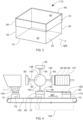
- a tray 10 employed in the process is shown in Fig. 1 .
- the tray 10 and hood can be formed of paperboard or corrugate.
- Paperboard and corrugate materials can comprise pulp.
- the paperboard or corrugate can have a thickness from 1 mm to about 3 mm.
- the paperboard or corrugate can be a laminate.
- the paperboard or corrugate can comprise pulp.
- the paperboard or corrugate can comprise colorants, preservatives, plasticizers, ultraviolet stabilizers, oxygen, perfume, recycled materials, moisture barriers, and combinations thereof.
- Corrugate can comprise a laminate of two sheets of paperboard having a fluted layer disposed between the two sheets of paperboard.
- Each of the tray 10 and hood can be a single piece of die cut paperboard or corrugate having a pattern of the faces of the tray 10 or hood and flaps extending from the faces or panels.
- the tray 10 or hood can be erected by joining a combination of the flaps or a combination of the flaps and faces or panels to erect the tray 10 or hood.
- the flaps and or faces or panels can be joined to one another by gluing, thermal bonding, fitting tabs to slots, and engaging interlocking structures.
- the tray 10 can be conveyed in a machine direction MD.
- the tray 10 can comprise a leading face 20 and a trailing face 30 upstream of the leading face.
- the tray 10 can have a front face 40 and a back face 50 opposite the front face 40.
- the front face 40 and the back face 50 extend from the leading face 20 to the trailing face 30 in the machine direction MD.
- the tray 10 can comprise a peripheral rim 15 defining a top opening of the tray 10.
- the tray 10 can have a longitudinal axis L in line with the machine direction MD.
- a hood 60 employed in the process is shown in Fig. 2 .
- the hood 60 can comprise a leading panel 70, trailing panel 80 opposite to and upstream of the leading panel 70, and a hood top 90 extending from the leading panel 70 to the trailing panel 80.
- the hood 60 can comprise a pair of opposing hood side peripheral edges 100.
- the hood 60 can be telescopically fitted to the tray 10 to form a closed package 110 ( Fig. 3 ).
- the high speed process for dispensing a product 1 into a tray 10 described herein can be part of an end to end process for packaging a product 1, as shown in Fig. 4 .
- the steps of the process can include manufacturing the product 1.
- the product 1 can be a substrate treatment composition.
- a tray carriage system 120 can be provided.
- the tray 10 can be provided and be movable in or on the tray carriage system 120.
- the tray 10 can be moved at the tray velocity TV via the tray carriage system 120 in the machine direction MD.
- the tray velocity TV can be constant or variable.
- a dispensing system 130 can be provided and the product 1 can be dispensed into the tray 10 via the dispensing system 130.
- the product 1 can be a water soluble unit dose laundry or dish cleaning product.
- the product 1 can be TIDE PODS, ARIEL 3 IN 1 PODS, FAIRY ALL IN ONE, CASCADE ACTION PACKS, CASCADE PLATINUM, and the like available from The Procter & Gamble Company.
- a hood engagement system 140 can be provided above the tray carriage system 120 and downstream of the dispensing system 130.
- the hood 60 is engaged with the tray 10 via the hood engagement system 140 to close the tray 10 to form the closed package 110.
- the hood engagement system 140 can be a rotary hood engagement system 140 that fits a hood 60 to a tray 10 as the tray 10 passes beneath the hood engagement system 140.
- the hood engagement system 140 can include a plurality of suction heads 145 that engage the hood top 90. The hood 60 can be picked up by the suction head 145 as the suction head 145 passes a hood magazine 147.
- the hood magazine 147 can serially feed a hood 60 to be engaged with the suction head 145 as the suction head 145 rotates past the hood magazine 147.
- the suction heads 145 can be mounted on a rotating turret 148. Suction applied to the suction head 145 holds the hood 60 against the section head 145. Movement and control of the rotating turret 148 and the tray carriage system 120 can be coupled so that the hood 60 can be fitted to a tray 10 as the tray passes beneath the hood engagement system 140.
- the angular velocity of the rotating turret 148 can be constant or variable. Rotation of the rotating turret 148 can be indexed so that the hood 60 can be fitted to a tray 10 passing beneath the rotating turret 148.
- suction on the suction head 145 can be released to drop the hood 60 and fit the hood 60 onto the tray 10.
- the suction head 145 can moved in the radial direction to push or slightly push the hood 60 onto the tray 10.
- the hood 60 and tray 10 can be engaged at a merging location 150 along the tray carriage system 120.
- the hood engagement system 140 can further comprise a hood guide 160 above the tray carriage system 120 at or in or downstream of the merging location 150.
- the hood guide 160 can be nearer to the tray carriage system 120 downstream of the merging location 150 than at the merging location 150.
- the hood guide 160 can contact the hood top 90 to telescopically fit the hood 60 onto the tray 10.
- the hood guide 160 can be a wedge that pushes the hood 60 to fit to the tray 10.
- the hood guide 160 can be a belt that is positioned at a small angle relative to the machine direction MD to force the hood 60 to fit to the tray.
- the closed package 110 can be further processed and shipped.
- the closed package 110 can be shipped to a distributor or distribution facility and further along the supply chain until it reaches a location at which a user can open the package 110 by removing the hood 60, retrieve the product 1 from the tray 10, and use the product 1.
- the tray 10 can have a front face fold back 42 that is an integral extension of the front face 40 folded towards the interior of the tray 10 along a front face fold line 44 ( Fig. 5 ).
- the tray 10 can have a back face fold back 52 that is an integral extension of the back face 50 folded towards the interior of the tray 10 along a back face fold line 54.
- the front face fold back 42 and back face fold back 52 can provide for additional rigidity to the peripheral rim 15 of the tray 10.
- a front face flap 46 can extend from the peripheral rim 15 along the front face 40.
- the front face flap 46 can extend from the front face 40 to a front face flap distal end 47.
- a back face flap 56 can extend from the peripheral rim 15 along the back face 50.
- the back face flap 56 can extend from the back face 50 to a back face flap distal end 57.
- the front face flap 46 and back face flap 56 can be structured from a cutlines on in the front face 40 and back face 50, respectively.
- the front face fold back 42 and back face fold back 52 can extend more deeply into the tray 10 than the cut lines that form the boundary of the front face flap 46 and back face flap 56.
- the front face fold line 44 and back face fold line 56 can be orthogonal to the flutes if the tray is constructed from corrugate.
- folding perpendicular to the flutes can provide for a hinge having springiness about the fold.
- the springiness can be employed to form a closure system that engages the hood 60 with the tray 10 that can be opened and closed multiple times.
- the blank from which the tray 10 is erected can include cut lines that define the shape and dimensions of the front face flap 46 and back face flap 56 and the cut lines can be positioned so that when the tray 10 is erected the front face flap 46 and the back face flap 56 are positioned as desired.
- the front face fold back 42 and back face fold back 52 can be folded towards the interior of the tray 10.
- the parts of the front face fold back 42 and the back face fold back 52 from which the front face flap 46 and the back face flap 56 extend, respectively, can be unfolded and pointing upward after the tray 10 is erected.
- the front face flap 46 and the back face flap 56 can protrude upwardly from the peripheral rim 15 of the tray 10.
- the front face flap 46 and the back face flap 56 can be folded outwardly away from the interior of the tray 10 before engaging the hood 60 with the tray 10.
- the front face flap 46 and the back face flap 56 can be held down while engaging the hood 60 with the tray 10.
- the front face flap 46 and the back face flap 56 can be outwardly folded by a pair of folding rails that are associated with the tray carriage system 120.
- the folding rails can be provided upstream of the hood engagement system 140.
- the folding rails can capture the distal ends of the flaps and movement of the tray 10 downstream and shaping of the folding rails can bend the front face flap 46 and the back face flap 56 outwardly away from the interior of the tray 10 so that the distal ends of the respect flaps are oriented towards the bottom of the tray 10.
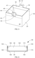
- the hood 60 can be provided with an engagement mechanism the cooperates with the front face flap 46 and back face flap 56, by way of nonlimiting example as shown in Fig. 6 .
- Fig. 7 is a cross section of a hood 60 looking in the upstream direction toward the hood trailing panel 80.
- the hood 60 can further comprise a front panel inwardly folded flap 172 extending from the front panel 170 and a back panel inwardly folded flap 182 extending from the back panel 180. Together the front panel 170 and back panel 180 can extend from the leading panel 70 to the trailing panel 80. And the front panel inwardly folded flap 172 and the back panel inwardly folded flap 182 can be between the front panel 170 and the back panel 180.
- the distal ends of the front face flap 46 and back face flap 56 can engage with the ends 190 of the front panel inwardly folded flap 172 and the back panel inwardly folded flap 182, respectively ( Fig. 7 ).
- the user can unlock the hood 60 from the tray 10 by pushing on the front face flap 46 and the back face flap 56 to release the distal ends of front face flap 46 and the back face flap 56 from contact with the ends 190 of the front panel inwardly folded flap 172 and the back panel inwardly folded flap 182, respectively.
- the front face flap 46 and the back face flap 56 rotate about a hinge formed by the front face fold line 44 and the back face fold line 54.
- the front face flap 46 can be accessed through an aperture 200 in the front panel 170.
- the back face flap 56 can be accessed through an aperture 200 in the back panel 180 ( Fig. 8 ).
- the hood engagement system 140 is the mechanism for positioning a hood 60 so that the hood 60 can be fitted to a tray 10 as the tray 10 moves downstream in the machine direction MD.
- a carriage system 120 comprising a plurality of linear motor vehicles 230 ( Fig. 9 ).
- the carriage system 120 can be a horizontally oriented track system in which movement of individual linear motor vehicles 230 is controlled.
- a suitable linear motor track system can be an ITRAK system from Rockwell Automation.
- a tray 10 can be conveyed by adjacent linear motor vehicles 230.
- Each linear motor vehicle 230 can have a restraint plate 240 attached thereto.
- the restraint plate 240 can be oriented orthogonal to the machine direction MD.
- Each tray 10 can be held by restraint plates 240 of adjacent linear motor vehicles 230.
- adjacent pairs of linear motor vehicles 230 can be individually controlled or controlled in pairs to hold a tray 10 between the restraint plates 240 of adjacent linear motor vehicles 230.
- the pitch P amongst trays 10 can be nonconstant and individually controlled.
- the position of individual trays 10 can be controlled to match up with the position of the hood 60 being fitted thereto.
- Vision systems or sensors can detect the position and speed of the hood 60 and a computer system can adjust the velocity of the tray 10 so that the hood 60 is fitted to a tray 10 as the tray 10 passes through the location at which the hood 60 merges with the tray 10.
- the carriage system 120 can be configured to convey the trays 10 in a condition in which the tray 10 is squeezed in the longitudinal direction so that the front face 40 and back face 50 are outwardly bowed away from the longitudinal axis L.
- the outward bowing of the front face 40 and the back face 50 can arise during manufacture of the flat paperboard or corrugate.
- the amount of force applied in the machine direction MD and counter to the machine direction MD by the carriage system 120 can increase the amount of bowing as compared to the amount of bowing that might arise due to manufacture of the flat paperboard or corrugate and that which might arise as a result of transforming the flat paperboard or corrugate into a three-dimensional tray 10.
- Outwardly bowing the front face 40 and the back face 50 can help provide for a tight fit between the hood 60 and the tray 10 and a secure engagement of the locking mechanism.
- the tray 10 can be bowed, by way of non-limiting example, in a carriage system 120 that employs linear motor vehicles 230 by controlling or setting the spacing between adjacent linear motor vehicles 230.
- the spacing between adjacent linear motor vehicles 230 can be set to be less than the distance between the leading face 20 and trailing face 30, as measured between the outer surfaces, of the tray 10 in an unloaded condition.
- the software operating the adjacent linear motor vehicles 230 can be programmed to control the amount of bowing desired at different positions along the carriage system 120, which may vary as a function of position.
- the hood 60 can comprise a front panel inwardly folded flap 172 and a back panel inwardly folded flap 182.
- the hood 60 can be sized and dimensioned to fit tightly with the tray 10 so that the tray 10 may be securely closed.
- the hood 60 can be further fitted to the tray 10 by providing a bumper 250 that pushes the hood 60 onto the tray 10 as the tray 10 moves further downstream in the machine direction MD ( Fig. 10 ).
- the bumper 250 can be configured to provide a reaction surface against which at least part of the hood 60 contacts.
- the distance between portions of the bumper 250 and the carriage system 120 can decrease as a function of distance in the machine direction.
- the bumper 250 can function as a wedge that pushes the hood 60 down onto the tray 10 as the tray 10 and hood 60 are conveyed in the machine direction downstream.
- the further fitting of the hood 60 to the tray 10 downstream of location at which the hood 60 is first fitted to the tray 10 can occur while the tray 10 is held and under the control of the carriage system 120.
- the hood 60 can be further telescopically fit to the tray 10.
- the bumper 250 can have a smooth surface that engages with the hood 60 so that the hood 60 slides easily along the bumper 250.
- the smooth surface of the bumper 250 can be a polished steel or aluminum surface or a plastic material such as an acetal plastic or other plastic material having a low coefficient of friction and a smooth finish.
- the bumper 250 can be a static bumper, a movable belt, a moveable rope, or the similar mechanism for applying force to fit the hood 60 more closely to the tray 10.
- the tray 10 and hood 60 engaged therewith can be handed off from the carriage system 120 to a downstream conveyor 260.
- a second bumper 250 can be positioned above the downstream conveyor 260 to further telescopically fit the hood 60 to the tray 10.
- the second bumper 250 can be wedge shaped or positioned to present a wedging surface to the hood 60 as the tray 10 and hood 60 are conveyed further downstream in the machine direction.
- the closed package 110 can be further processed and or finished and shipped from the location at which the closed package 110 is assembled.
- the closed package 110 can be shipped to a distribution center, customers, or consumers to finally reach the location at which the user opens the package 110 to use or consume the contents of the package 110.
- a dispensing system 130 can be provided and the product 1 can be dispensed into the tray 10 via the dispensing system 130.
- a hood engagement system 140 can be provided above the tray carriage system 120 and downstream of the dispensing system 130.
- the hood 60 is engaged with the tray 10 via the hood engagement system 140 to close the tray 10 to form the closed package 110.
- the hood 60 can be engaged with the tray 10 while the tray 10 is moving in the machine direction MD.
- the closed package 110 can be shipped.
- the closed package 110 can be shipped to a distributor or distribution facility and further along the supply chain until it reaches a location at which a user can open the package 110 by removing the hood 60, retrieve the product 1 from the tray 10, and use the product 1.
- the hood 60 may tightly conform to the tray 10 to provide for a robust connection between the hood 60 and tray 10 for the closed package 110. If the conformance between the hood 60 and the tray 10 is tight, processes that operate at a fixed rate with little or no control over movement of one or both of the hood 60 and tray 60 may be inadequate to enable the tray 10 to catch a hood 60 as the hood merges with the tray 10.
- the dispensing system 130 can be a hopper, for example a clamshell hopper, that opens when a tray 10 is beneath the dispensing system 130 to drop products 1 into the tray. With the hopper in the closed position, a certain count or weight of products 1 can be fed into the hopper. When a tray is passing beneath the hopper, the hopper can open and drop the products 1 into the tray 10.
- the dispensing system 130 can be chute into which a certain count or weight of products 1 are fed and directed into a tray 10 passing beneath the dispensing system.
- the dispensing system 130 can be a gated chute. When the gate is closed products 1 can be fed into the chute.
- the dispensing system 130 can be horizontal or vertically oriented carousel for dispensing a certain count or weight of products 1.
- the dispensing system 130 can include a shuttle and dispense products 1 as the dispensing system 130 moves downstream in the machine direction MD and then shuttles back upstream to dispense products 1 into the next arriving tray 10.
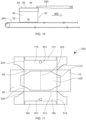
- the hood 60 can be erected from a flat blank 300 ( Fig. 11 ).
- the flat blank 300 can comprise a leading panel 70, a trailing panel 80 opposite the leading panel 70, and hood top 90 extending between the leading panel 70 and the trailing panel 80.
- the flat blank 300 can further comprise a front panel 170 and the back panel 180.
- the flat blank 300 can be provided with a plurality of fold lines. When the hood 60 is erected, the flat blank 300 can be folded about the fold lines to transform the flat blank 300 from an essentially two-dimensional structure into a three-dimensional structure.
- the fold lines can be continuous or intermittent.
- the fold lines can be a preferentially weakened portion of the flat blank 300.
- the fold lines can be formed by indenting the paperboard or corrugate from which the flat blank 300 is constructed.
- the fold lines can be formed by scoring the paperboard or corrugate from which the flat blank 300 is constructed.
- the flat blank 300 can comprise a leading fold line 310 between the leading panel 70 and the hood top 90.
- the flat blank 300 can comprise a trailing fold line 320 between trailing panel 80 and the hood top 90.
- the flat blank 300 can further comprise side fold lines 315.
- the side fold lines 315 form the boundary between the hood top 90 and each of the front panel 170 and back panel 180.
- the flat blank 300 can further comprise a central fold line 325 parallel to the leading folding line 310 and the trailing fold line 320.
- the central fold line 325 can provide a line about which the central portion 330 can bend to become spaced apart from the hood top 90 at a desired location.
- a flat insert 330 can be adhered to a panel selected from the group of the leading panel 70, the trailing panel 80, and combinations thereof.
- the flat insert 330 can be adhered to a surface selected from the group of the leading panel 70, the trailing panel 80, the hood top 90, and combinations thereof.
- the flat insert 330 has a central portion 340 between the leading fold line 310 and the trailing fold line 320. The central portion 340 can be unattached to the hood top 90.
- the flat insert 330 When erected, the flat insert 330 is transformed into a three-dimensional shape that provides structural support behind the front face flap 46 and the back face flap 56.
- the locking mechanism between the hood 60 and the tray 10 relies on the end 190 of the of the front panel inwardly folded flap 172 abutting the front face distal end 47 of the front face flap 46 and the end 190 of the back panel inwardly folded flap 182 abutting the back face distal end 57 of the back face flap 56.
- the user can push the front face flap 46 and back face flap 56 to disengage the front face flap 46 and the back face flap 56 from the end 190 of the front panel inwardly folded flap 172 and the end 190 of the back panel inwardly folded flap 182, respectively.
- the tray 10 may fail to engage at all with an end 190.
- the front panel 170 and the back panel 180 can comprise a predetermined removable portion 201.
- the predetermined removable portion 201 can be a partial die cut or perforation that defines the shape of the predetermined removeable portion 201.
- the user can punch out the predetermined removable portions 201 to form the apertures 200. The user can then access the front face flap 46 and the back face flap 56 to disengage the hood 60 from the tray 10.
- the flat insert 330 can be corrugate having flutes and the flutes extending in a direction between the front panel 170 and the back panel 180.
- the flat insert 330 can be paperboard.
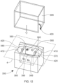
- the hood 60 can be erected using a die 350 and a hood mold 395 ( Fig. 12 ).
- the die 350 can be positioned in facing relationship with the flat blank 300 and punched into a mold to transform the flat blank 300 into the hood 60.
- the central portion 340 of the flat insert 330 can become spaced apart from the hood top 90.
- the die 350 can be metal, plastic, or an assembly of components of metal and plastic.
- the die 350 comprises a die recess 360.
- the die recess 360 can accommodate separation of the central portion 340 from the hood top 90.
- the central portion 340 when spaced apart from the hood top 90, can provide for structural support behind the front face flap 46 and the back face flap 56 to limit undesirable deformation of the front face 40 and back face 50 near the front face flap 46 and the back face flap 56.
- the die 350 can comprise a leading edge 370 and trailing edge 380 and a pair of side edges 390 extending from the leading edge 370 to the trailing edge 380.
- the die 350 can comprise a die recess 360 that is recessed relative to the leading edge 370, the trailing edge 380 and the side edges 390.
- the hood mold 395 which comprises a cavity 400, can be provided.
- the cavity 400 provides the three-dimensional space to accommodate the erected hood 60.
- the flat insert 330 is oriented towards the die recess 360.
- the leading fold line 310 can be positioned in line with the leading edge 370 of the die 350.
- the trailing fold line 320 can be positioned in line with the trailing edge 380.
- the die 350 can be positioned within the hood mold 395 to fold the flat blank 300 about the leading fold line 310 and the trailing fold line 320 and to fold the flat insert 330 coincidentally with the leading fold line 310 and the trailing fold line 320.
- the central portion 340 is spaced apart from the hood top 90.
- the die 350 can be pressed into the hood mold 30.
- the hood mold 30 can be pressed to fit over the die 350.
- both the die 350 and the hood mold 30 can be pressed so that the die 350 is within the hood mold 30.
- the portions of the flat insert 330 adhered thereto are also bent about the relevant fold line. Since the flat insert 330 is adhered to a panel selected form the leading panel 70, the trailing panel 80, and combinations thereof, there is no shear displacement between the flat insert 330 and the panel or panels to which the flat insert 330 is attached.
- the radius of the bend of the flat insert 330 is smaller than the radius of the bend between the leading panel 70 and the hood top 90 and the radius of the bend between the trailing panel 80 and the hood top 90.
- the die recess 360 can provide for space to accommodate the out of plane deformation of the central portion 340.
- the central fold line 325 can provide for controlled deformation of the central portion 340.
- the central fold line 325 can be midway between the leading fold line 310 and the trailing fold line 320. Providing a central fold line 325 can help to center the location where the maximum separation between the central portion 340 the hood top 90 occurs. By centering such location, the central fold line 325 can proximal or even behind the location of the front face flap 42 and the back face flap 56 when the hood 60 is engaged with the tray 10. At least part of the central portion 340 can form an angle about the central fold line 325.
- the die 350 can further comprise a pair of flat insert seating areas 410.
- One of the flat insert seating areas 410 can be between the leading edge 370 and the die recess 360 and another of the flat seating areas 410 can be between the trailing edge 380 and the die recess 360.
- the flat insert seating areas 410 can be sized and dimensioned to accommodate portions of the flat insert 330 that are adjacent the leading fold line 310 and the trailing fold line 320. That is, the flat insert seating areas 410 can be sized and dimensioned to accommodate portions of the flat insert 330 that extend beyond die recess 360.
- the flat insert seating areas 410 provide space within which the flat insert 330 can be seated so that when the die 350 is fitted with in the hood mold 395, portions of the flat insert 330 near the leading edge 370 and the trailing edge 380 do interfere with forming precise fold lines between the hood top 90 and the leading panel 70 and the hood top 90 and the trailing panel 80. Sizing and dimensioning the flat insert seating areas 410 to have a shape that is the same as or closely similar to the shapes of the flat insert 330 that extend beyond the die recess 360 can provide for crisper folding at the boundary between the hood top 90 and the leading panel 70 and trailing panel 80 since the die 350 can contact more of the surface of the flat blank 300.
- the flat insert seating areas 410 can be recessed relative to the side edges 290 and be sized and dimensioned to accommodate portions of the flat insert 330 that extend beyond the die recess 360. In such an arrangement, the flat insert 330 may not interfere with formation of crisp folds between the hood top 90 and the front panel 170 and back panel 180 as well as between the hood top 90 and the leading panel 70 and trailing panel 80.
- a tab 420 can project above the flat insert seating areas 410.
- Each tab 420 can be located at or near, or substantially at or near, the boundary between each flat insert seating area 410 and the die recess 360.
- these tabs 420 can induce a fold line to form in the flat insert 330 at or near the boundary between the flat insert seating areas 410 and the die recess 360.
- This can be beneficial in that it can provide for a shaped transition between the central portion 340 that is spaced apart from the hood top 90 and the locations where the flat insert 330 is bent about the leading edge 370 and the trailing edge 380.
- the central portion 340 may be under residual stress and the shaped transition may help to direct these residual stresses to be predominantly orthogonal to the leading panel 70 and the trailing panel 80.
- the tabs 420 can project 0.5 mm to about 3 mm, optionally 2 mm, above the side edges 390.
- the side edges 390 can define a forming plane 430 and the tabs 420 can project above the forming plane 430 (i.e. in a direction away from the die recess 360).
- the die 350 can further comprise vent holes 385 within the die recess 360.
- the vent holes 385 can be beneath the side edges 390.
- the vent holes 385 can be elevationally lower than both the side edges 390 and the flat insert seating areas 410.
- the vent holes 385 can permit air to escape from the die recess 360 as the central portion 330 deforms inwardly into the die recess 360 and is spaced apart from the hood top 90.
- the die recess 360 can have an adjustable volume.
- the adjustable volume can be provided for by a die 350 that is extendable and contractable in that the distance between the leading edge 370 and the trailing edge 380 is adjustable ( Fig. 13 ).
- Such a die 350 can be practical to use for erecting hoods 60 of different sizes as define by the distance between the leading fold line 310 and the trailing fold line 320.
- An extendable and contractable die 350 can be provide by the die sidewalls 351 comprising a plurality sidewall segments 352.
- the sidewall segments can define or partially define the die recess 360.
- the sidewall segments 352 can be positioned to abut one another to provide for a small hood 60.
- the sidewall segments 352 can be positioned spaced apart from one another to form a large hood 60.
- the sidewall segments 352 permit the distance between the leading edge 370 and the trailing edge 380 to be fixed at different distances.
- FIG. 14 A cross section of a hood 60 is shown in Fig. 14 .
- the hood 60 can comprise a pair of opposing predetermined removable portions 201 or apertures. As shown in Fig. 14 , when the central portion 340 is spaced apart from the hood top 90, at least part of the central portion 340 can be positioned between the opposing predetermined removable portions 201 or apertures.
- Insert bend lines 421 are illustrated in Fig. 14 , which can occur when the die 350 is provided with tabs 420 as described herein.
- the pair of insert bend lines 421 can be on opposite sides of the central fold line 325.
- One insert bend line 421 can be between the central fold line 325 and the leading panel 70.
- One insert bend line 421 can be between the central fold line 325 and the trailing panel 80.
- the flat insert 330 can be adhered to a panel selected from the leading panel 70, the trailing panel 80, and combinations thereof, by adhesive 440.
- the central bend lines 421 can be positioned so that when the central portion 340 is fitted to the die 350, they are near or at, or substantially near or at, the boundary between the flat insert seating areas 410 and the die recess 360.
- the central bend lines 421 can be positioned so that when the central portion 340 is fitted to the die 350, they are near or at, or substantially near or at, the locations of the tabs 420 that are optionally present at the boundary between the flat insert seating areas 410 and the die recess 360.
- FIG. 15 A partial cross section of another hood is shown in Fig. 15 .
- the central portion 340 can be positioned to provide structural support behind the front face flap 46 and the back face flap 56.
- the central portion can 340 can limit deformation of the tray near the front face flap 46 and the back face flap 56.
Landscapes
- Engineering & Computer Science (AREA)
- Mechanical Engineering (AREA)
- Microelectronics & Electronic Packaging (AREA)
- Cartons (AREA)
- Packaging Of Machine Parts And Wound Products (AREA)
- Making Paper Articles (AREA)
Claims (15)
- Verfahren zum Verpacken eines Produkts (1), umfassend die Schritte:Fertigen des Produkts, wobei das Produkt eine Substratbehandlungszusammensetzung (2) ist;Bereitstellen eines Schalentransportsystems (120);Bereitstellen einer Schale (10), die in oder auf dem Schalentransportsystem bewegbar ist;Bewegen der Schale über das Schalentransportsystem in einer Maschinenrichtung (MD);Bereitstellen eines Abgabesystems (130) über dem Schalentransportsystem;Abgeben des Produkts in die Schale über das Abgabesystem;Bereitstellen eines Haubeneingriffssystems (140) über dem Schalentransportsystem und unterhalb des Abgabesystems;Bereitstellen einer Haube (60), die in dem Haubeneingriffssystem bewegbar ist, dadurch gekennzeichnet, dass die Haube durch ein Verfahren errichtet wird, umfassend die Schritte:Bereitstellen eines flachen Zuschnitts (300), umfassend ein vorderes Feld (70), ein hinteres Feld (80), das dem vorderen Feld entgegengesetzt ist, ein Haubenoberteil (90), das sich zwischen dem vorderen Feld und dem hinteren Feld erstreckt, eine vordere Faltlinie (310) zwischen dem vorderen Feld und dem Haubenoberteil und eine hintere Faltlinie (320) zwischen dem hinteren Feld und dem Haubenoberteil umfasst;Bereitstellen eines flachen Einsatzes (330), der an einem Feld anhaftet, das aus der Gruppe des vorderen Felds, des hinteren Felds und Kombinationen davon ausgewählt ist, wobei der flache Einsatz einen Mittelabschnitt (340) zwischen der vorderen Faltlinie und der hinteren Faltlinie aufweist und wobei der Mittelabschnitt nicht an dem Haubenoberteil befestigt ist;Bereitstellen einer Matrize (350), umfassend einen vorderen Rand (370) und einen hinteren Rand (380), ein Paar von Seitenrändern (390), die sich von dem vorderen Rand zu dem hinteren Rand erstrecken, und eine Matrizenaussparung (360), wobei die Matrizenaussparung relativ zu dem vorderen Rand, dem hinteren Rand und den Seitenrändern ausgespart ist;Bereitstellen einer Haubengießform (395), die einen Hohlraum (400) aufweist;Ausrichten des flachen Einsatzes in Richtung der Matrizenaussparung; undPositionieren der Matrize innerhalb der Haubengießform, um den flachen Zuschnitt um die vordere Faltlinie und die hintere Faltlinie herum zu falten und um den flachen Einsatz gleichzeitig mit mindestens einer der vorderen Faltlinie und der hinteren Faltlinie zu falten, wodurch der Mittelabschnitt von dem Haubenoberteil beabstandet ist;Ineingriffnehmen der Haube mit der Schale über das Haubeneingriffssystem, um den Einsatz innerhalb der Schale einzupassen und die Schale zu schließen, um eine geschlossene Verpackung (110) auszubilden; undVersenden der geschlossenen Verpackung.
- Verfahren nach Anspruch 1, wobei die Matrize in die Haubengießform gepresst wird.
- Verfahren nach Anspruch 1 oder 2, wobei der flache Einsatz eine Mittelfaltlinie aufweist, die parallel zu der vorderen Faltlinie und zu der hinteren Faltlinie verläuft.
- Verfahren nach einem der vorstehenden Ansprüche, wobei die Matrize ein Paar von flachen Einsatzsitzbereichen (410) aufweist, wobei sich einer der flachen Einsatzsitzbereiche zwischen dem vorderen Rand und der Matrizenaussparung und ein anderer der flachen Einsatzsitzbereiche zwischen dem hinteren Rand und der Matrizenaussparung befindet.
- Verfahren nach Anspruch 4, wobei die flachen Einsatzsitzbereiche relativ zu den Seitenrändern ausgespart sind, wobei die flachen Einsatzsitzbereiche bemessen und dimensioniert sind, um Abschnitte des flachen Einsatzes aufzunehmen, die sich über die Matrizenaussparung hinaus erstrecken.
- Verfahren nach Anspruch 4 oder 5, wobei zwischen mindestens einem Teil jedes flachen Einsatzsitzbereichs und der Matrizenaussparung eine Lasche (420) über die flachen Einsatzsitzbereiche hervorsteht.
- Verfahren nach Anspruch 6, wobei die Seitenränder eine Ausbildungsebene (430) definieren, wobei die Laschen über die Ausbildungsebene hervorstehen.
- Verfahren nach einem der vorstehenden Ansprüche, wobei die Haube mindestens einen vorher festgelegten abnehmbaren Abschnitt (201) oder eine Öffnung aufweist, wobei, wenn der Mittelabschnitt von dem Haubenoberteil beabstandet ist, mindestens ein Teil des Mittelabschnitts hinter dem vorher festgelegten abnehmbaren Abschnitt oder der Öffnung positioniert ist.
- Verfahren nach einem der vorstehenden Ansprüche, wobei der flache Einsatz an dem vorderen Feld und dem hinteren Feld anhaftet.
- Verfahren nach einem der vorstehenden Ansprüche, wobei der flache Einsatz übereinstimmend mit der vorderen Faltlinie und der hinteren Faltlinie gefaltet wird.
- Verfahren nach einem der vorstehenden Ansprüche, wobei die Haube ein Paar von einander entgegengesetzten, vorher festgelegten, entfernbaren Abschnitten (201) oder Öffnungen umfasst, wobei wenn der Mittelabschnitt von dem Haubenoberteil beabstandet ist und mindestens ein Teil des Mittelabschnitts zwischen den einander entgegengesetzten, vorher festgelegten, entfernbaren Abschnitten oder Öffnungen positioniert ist.
- Verfahren nach einem der vorstehenden Ansprüche, wobei die Schale eine Vorderfläche (40), eine Rückfläche (50), die der Vorderfläche entgegengesetzt ist, eine Vorderflächenklappe (46), die sich von der Vorderfläche zu einem distalen Ende (47) der Vorderflächenklappe erstreckt, und eine Rückflächenklappe (56), die sich von der Rückfläche (50) zu einem distalen Ende (57) der Rückflächenklappe erstreckt, umfasst, wobei die Haube eine Vorderflächenrückfaltung (42), die eine integrale Verlängerung der Vorderfläche ist, und eine entgegengesetzte Rückflächenrückfaltung (52) umfasst, die eine integrale Verlängerung der Rückfläche ist, wobei das distale Ende der Vorderflächenklappe mit der Vorderflächenrückfaltung in Eingriff steht und das distale Ende der Rückflächenklappe mit der Rückflächenrückfaltung in Eingriff steht.
- Verfahren nach einem der vorstehenden Ansprüche, wobei der Mittelabschnitt eine Mittelfaltlinie (325) umfasst und mindestens ein Teil des Mittelabschnitts einen Winkel um die Mittelfaltlinie herum ausbildet.
- Verfahren nach Anspruch 13, wobei der Mittelabschnitt ein Paar von Einsatzbiegelinien (421) auf entgegengesetzten Seiten der Mittelfaltlinie umfasst.
- Verfahren nach einem der Ansprüche 1 bis 14, wobei die Matrize ein oder mehrere Entlüftungslöcher 385 innerhalb der Matrizenaussparung umfasst.
Priority Applications (1)
| Application Number | Priority Date | Filing Date | Title |
|---|---|---|---|
| RS20250310A RS66654B1 (sr) | 2022-01-14 | 2022-12-13 | Proces za formiranje haube za posudu |
Applications Claiming Priority (1)
| Application Number | Priority Date | Filing Date | Title |
|---|---|---|---|
| US202263299582P | 2022-01-14 | 2022-01-14 |
Publications (2)
| Publication Number | Publication Date |
|---|---|
| EP4238876A1 EP4238876A1 (de) | 2023-09-06 |
| EP4238876B1 true EP4238876B1 (de) | 2025-03-05 |
Family
ID=84519883
Family Applications (1)
| Application Number | Title | Priority Date | Filing Date |
|---|---|---|---|
| EP22213141.9A Active EP4238876B1 (de) | 2022-01-14 | 2022-12-13 | Verfahren zur herstellung einer haube für eine schale |
Country Status (6)
| Country | Link |
|---|---|
| US (2) | US11851232B2 (de) |
| EP (1) | EP4238876B1 (de) |
| ES (1) | ES3023359T3 (de) |
| PL (1) | PL4238876T3 (de) |
| RS (1) | RS66654B1 (de) |
| WO (1) | WO2023137410A1 (de) |
Families Citing this family (10)
| Publication number | Priority date | Publication date | Assignee | Title |
|---|---|---|---|---|
| ES2932508T3 (es) | 2020-05-08 | 2023-01-20 | Procter & Gamble | Recipiente de producto detergente con cierre |
| EP4446244B1 (de) | 2020-07-09 | 2025-08-06 | The Procter & Gamble Company | Deckel für einen kartonbehälter, wobei der deckel ein kartonträgerelement aufweist |
| HUE064933T2 (hu) | 2020-07-09 | 2024-05-28 | Procter & Gamble | Mosószertermék és tároló |
| EP4257498A3 (de) | 2020-12-11 | 2024-01-03 | The Procter & Gamble Company | Waschmittelproduktbehälter mit schloss |
| EP4039607B1 (de) * | 2021-02-09 | 2023-08-16 | The Procter & Gamble Company | Behälter mit abdeckung, schloss und ausrichtmarkierung |
| EP4059857B1 (de) | 2021-03-15 | 2023-07-12 | The Procter & Gamble Company | Reinigungsmittelbehälter mit verriegelung und querwand |
| EP4238876B1 (de) * | 2022-01-14 | 2025-03-05 | The Procter & Gamble Company | Verfahren zur herstellung einer haube für eine schale |
| EP4242116A1 (de) | 2022-02-11 | 2023-09-13 | The Procter & Gamble Company | Hochgeschwindigkeitsfüllung einer schale |
| CN118103296A (zh) | 2022-02-11 | 2024-05-28 | 宝洁公司 | 盒和罩盖的高速套装装配 |
| CN117302661B (zh) * | 2023-11-28 | 2024-02-06 | 四川威纳尔特种电子材料有限公司 | 一种芯片封装用键合丝卷料的自动装盒装置及方法 |
Family Cites Families (44)
| Publication number | Priority date | Publication date | Assignee | Title |
|---|---|---|---|---|
| US3366496A (en) | 1965-07-29 | 1968-01-30 | Int Paper Co | Food packaging process |
| US4420924A (en) * | 1981-09-01 | 1983-12-20 | Kliklok Corporation | Apparatus and method for inverting and applying flanged lids to erected cartons |
| US5450998A (en) * | 1993-12-20 | 1995-09-19 | General Mills, Inc. | Fabricated on demand totes |
| US5494161A (en) | 1994-07-08 | 1996-02-27 | Fellowes Manufacturing Company | Hanging folder file box |
| US5505374A (en) | 1995-07-13 | 1996-04-09 | Packaging Corporation Of America | Flip-top reclosable carton and method of making the same |
| US5725144A (en) | 1996-06-26 | 1998-03-10 | Tenneco Packaging | Collapsible paperboard carton |
| US6604676B2 (en) | 1999-12-29 | 2003-08-12 | Unilever Home & Personal Care Usa, Division Of Conopco, Inc. | Lip-lock carton for powders |
| US6484478B1 (en) | 2000-01-24 | 2002-11-26 | Illinois Tool Works Inc. | System and method for packaging oriented containers |
| US6484479B1 (en) * | 2000-04-10 | 2002-11-26 | Tetra Laval Holdings & Finance, Sa | Form, fill and seal apparatus with cavity bar |
| JP4536881B2 (ja) | 2000-07-19 | 2010-09-01 | ザ・パック株式会社 | 蓋付き包装用紙箱 |
| AU7121101A (en) | 2000-07-24 | 2002-02-25 | Munksjoe Ab | Case |
| FR2820718B1 (fr) | 2001-02-15 | 2003-07-25 | Smurfit Socar Sa | Emballage en un materiau semi-rigide, comprenant deux parties assemblables en une pluralite de positions reglables |
| IT1401038B1 (it) * | 2010-06-30 | 2013-07-12 | Emmeci Spa | Apparato e procedimento per la realizzazione di scatole rivestite a spigolo vivo |
| US8646680B2 (en) | 2012-01-30 | 2014-02-11 | OIA Global Logistics SCM, INC. | Sheet and folding method for self-latching clamshell folded box |
| US8596520B2 (en) | 2012-04-16 | 2013-12-03 | International Paper Co. | Waterproof and anti-wicking corrugated container |
| AU2014385940B2 (en) * | 2014-03-14 | 2019-05-23 | Rengo Co., Ltd. | Packing box and box manufacturing apparatus |
| US9881788B2 (en) | 2014-05-22 | 2018-01-30 | Lam Research Corporation | Back side deposition apparatus and applications |
| US9783335B2 (en) | 2015-02-27 | 2017-10-10 | Munson Whitman Everett | Child-resistant packaging systems and methods |
| US10017291B2 (en) | 2015-05-04 | 2018-07-10 | Multi Packaging Solutions, Inc. | Child resistant locking packaging |
| CA2996273A1 (en) | 2015-08-24 | 2017-03-02 | Vinay K. Mehta | Ventilation boards and methods for manufacturing ventilation board |
| US9994356B2 (en) | 2016-03-16 | 2018-06-12 | Westrock Shared Services, Llc | Blanks and methods for forming a shelf-ready display container |
| US10232976B2 (en) | 2016-07-25 | 2019-03-19 | Graphic Packaging International, Llc | Dispensing carton |
| US10730671B2 (en) | 2017-03-07 | 2020-08-04 | JohnsByrne Company | Child resistant packaging |
| US10934072B2 (en) | 2017-08-31 | 2021-03-02 | Lantz Packaging, LLC | Child-resistant senior-friendly packaging |
| MA49970A (fr) | 2018-06-29 | 2020-07-01 | Van Genechten Packaging N V | Boîte pliante |
| US11097867B1 (en) | 2018-09-11 | 2021-08-24 | Wexxar Packaging, Inc. | Method and blank configuration for forming a ready to display tray |
| HUE065566T2 (hu) | 2019-06-19 | 2024-06-28 | Dalli Werke Gmbh & Co Kg | Gyerekzárral ellátott csomagolás |
| US20210047072A1 (en) | 2019-08-14 | 2021-02-18 | The Procter & Gamble Company | Consumer product |
| US11530058B2 (en) * | 2020-01-31 | 2022-12-20 | Sparck Technologies B.V. | System and method for automatically closing boxes with cardboard lids |
| HUE064933T2 (hu) | 2020-07-09 | 2024-05-28 | Procter & Gamble | Mosószertermék és tároló |
| ES2992935T3 (en) * | 2020-07-09 | 2024-12-19 | Procter & Gamble | Detergent product container |
| EP4446244B1 (de) | 2020-07-09 | 2025-08-06 | The Procter & Gamble Company | Deckel für einen kartonbehälter, wobei der deckel ein kartonträgerelement aufweist |
| EP3954534A1 (de) * | 2020-08-14 | 2022-02-16 | Quadient Technologies France | Klappenfalteinheit, klappenfaltvorrichtung, klappfaltverfahren und systeme und verfahren mit verwendung davon |
| EP3967617B1 (de) | 2020-09-15 | 2023-07-05 | The Procter & Gamble Company | Kartondeckel, kartonzuschnitt, verfahren zur herstellung eines konsumguts |
| EP4257498A3 (de) | 2020-12-11 | 2024-01-03 | The Procter & Gamble Company | Waschmittelproduktbehälter mit schloss |
| ES2999649T3 (en) | 2021-02-09 | 2025-02-26 | Procter & Gamble | Cover with tactile discontinuity |
| EP4039607B1 (de) | 2021-02-09 | 2023-08-16 | The Procter & Gamble Company | Behälter mit abdeckung, schloss und ausrichtmarkierung |
| EP4039606A1 (de) | 2021-02-09 | 2022-08-10 | The Procter & Gamble Company | Verbraucherprodukt |
| PL4039605T3 (pl) | 2021-02-09 | 2024-04-15 | The Procter & Gamble Company | Pokrywka z pierwszym, drugim i trzecim obszarem uruchamiania |
| EP4059857B1 (de) | 2021-03-15 | 2023-07-12 | The Procter & Gamble Company | Reinigungsmittelbehälter mit verriegelung und querwand |
| EP4238876B1 (de) | 2022-01-14 | 2025-03-05 | The Procter & Gamble Company | Verfahren zur herstellung einer haube für eine schale |
| EP4242116A1 (de) | 2022-02-11 | 2023-09-13 | The Procter & Gamble Company | Hochgeschwindigkeitsfüllung einer schale |
| CN118103296A (zh) | 2022-02-11 | 2024-05-28 | 宝洁公司 | 盒和罩盖的高速套装装配 |
| US20230322455A1 (en) | 2022-04-12 | 2023-10-12 | The Procter & Gamble Company | Prism forming cardboard support element with folding regions |
-
2022
- 2022-12-13 EP EP22213141.9A patent/EP4238876B1/de active Active
- 2022-12-13 RS RS20250310A patent/RS66654B1/sr unknown
- 2022-12-13 ES ES22213141T patent/ES3023359T3/es active Active
- 2022-12-13 PL PL22213141.9T patent/PL4238876T3/pl unknown
-
2023
- 2023-01-12 US US18/096,172 patent/US11851232B2/en active Active
- 2023-01-13 WO PCT/US2023/060601 patent/WO2023137410A1/en not_active Ceased
- 2023-11-10 US US18/506,351 patent/US12139291B2/en active Active
Also Published As
| Publication number | Publication date |
|---|---|
| US20230227186A1 (en) | 2023-07-20 |
| WO2023137410A1 (en) | 2023-07-20 |
| PL4238876T3 (pl) | 2025-06-09 |
| US12139291B2 (en) | 2024-11-12 |
| US11851232B2 (en) | 2023-12-26 |
| ES3023359T3 (en) | 2025-05-30 |
| US20240076074A1 (en) | 2024-03-07 |
| RS66654B1 (sr) | 2025-05-30 |
| EP4238876A1 (de) | 2023-09-06 |
Similar Documents
| Publication | Publication Date | Title |
|---|---|---|
| US12139291B2 (en) | Process for forming a hood for a tray | |
| EP4242121A1 (de) | Hochgeschwindigkeits-teleskop-beschlag von ablage und haube | |
| US12275546B2 (en) | High speed filling of a tray | |
| US7857743B2 (en) | Blank, apparatus and method for constructing container | |
| CA1121199A (en) | Method and apparatus for forming a flanged tray | |
| US7530381B2 (en) | Transfer glue system and method for a right angle gluing machine | |
| US20090095801A1 (en) | Methods and Apparatus for Manufacture of a Reclosable Plastic Carton | |
| CN103129844A (zh) | 双重可重新闭合的分配器纸盒 | |
| IE64249B1 (en) | Method and machine for forming cases with polygonal section made from a sheet material and cases thus obtained | |
| CA2928558A1 (en) | Child resistant locking packaging | |
| US4519181A (en) | Sleeve carton end panel and flap folding and sealing assembly | |
| US20070142193A1 (en) | Blank and methods and apparatus for forming a dispenser case from the blank | |
| US5669551A (en) | Packaging for books and/or other products and method and apparatus of the production thereof | |
| US7587884B2 (en) | Method and machine for adjusting the height of crates with square or rectangular cross section, for example for shipping goods | |
| US5439167A (en) | Package made of cardboard | |
| US12344416B2 (en) | Device and method for setting up containers having a functional edge from flat blanks | |
| EP2731881B1 (de) | Verpackungsverfahren und einheit zur herstellung eines festen pakets mit einer hohlen rippe | |
| US3792646A (en) | Apparatus for manufacturing a tray for packaging goods in shrinkable sheeting | |
| GB2229710A (en) | Packages formed from blanks | |
| EP0682629B1 (de) | Blisterpackung und verfahren zu ihrer herstellung | |
| BE1027621B1 (nl) | Valse rillen uitsnijden | |
| WO2017003451A1 (en) | Tissue packaging apparatus | |
| HK1187028A (en) | Process and machine for reducing the height of boxes with a square or rectanqular cross section | |
| MXPA98006393A (en) | Machine formadora de concipients horizon | |
| MXPA97010202A (en) | Type container box of material lami |
Legal Events
| Date | Code | Title | Description |
|---|---|---|---|
| PUAI | Public reference made under article 153(3) epc to a published international application that has entered the european phase |
Free format text: ORIGINAL CODE: 0009012 |
|
| STAA | Information on the status of an ep patent application or granted ep patent |
Free format text: STATUS: THE APPLICATION HAS BEEN PUBLISHED |
|
| AK | Designated contracting states |
Kind code of ref document: A1 Designated state(s): AL AT BE BG CH CY CZ DE DK EE ES FI FR GB GR HR HU IE IS IT LI LT LU LV MC ME MK MT NL NO PL PT RO RS SE SI SK SM TR |
|
| STAA | Information on the status of an ep patent application or granted ep patent |
Free format text: STATUS: REQUEST FOR EXAMINATION WAS MADE |
|
| 17P | Request for examination filed |
Effective date: 20240229 |
|
| RBV | Designated contracting states (corrected) |
Designated state(s): AL AT BE BG CH CY CZ DE DK EE ES FI FR GB GR HR HU IE IS IT LI LT LU LV MC ME MK MT NL NO PL PT RO RS SE SI SK SM TR |
|
| GRAP | Despatch of communication of intention to grant a patent |
Free format text: ORIGINAL CODE: EPIDOSNIGR1 |
|
| STAA | Information on the status of an ep patent application or granted ep patent |
Free format text: STATUS: GRANT OF PATENT IS INTENDED |
|
| GRAJ | Information related to disapproval of communication of intention to grant by the applicant or resumption of examination proceedings by the epo deleted |
Free format text: ORIGINAL CODE: EPIDOSDIGR1 |
|
| STAA | Information on the status of an ep patent application or granted ep patent |
Free format text: STATUS: REQUEST FOR EXAMINATION WAS MADE |
|
| RIC1 | Information provided on ipc code assigned before grant |
Ipc: B65B 43/52 20060101ALI20240821BHEP Ipc: B65B 7/28 20060101ALI20240821BHEP Ipc: B65B 5/02 20060101ALI20240821BHEP Ipc: B65B 1/02 20060101AFI20240821BHEP |
|
| GRAP | Despatch of communication of intention to grant a patent |
Free format text: ORIGINAL CODE: EPIDOSNIGR1 |
|
| STAA | Information on the status of an ep patent application or granted ep patent |
Free format text: STATUS: GRANT OF PATENT IS INTENDED |
|
| INTG | Intention to grant announced |
Effective date: 20240904 |
|
| INTC | Intention to grant announced (deleted) | ||
| INTG | Intention to grant announced |
Effective date: 20241009 |
|
| P01 | Opt-out of the competence of the unified patent court (upc) registered |
Free format text: CASE NUMBER: APP_60198/2024 Effective date: 20241107 |
|
| GRAS | Grant fee paid |
Free format text: ORIGINAL CODE: EPIDOSNIGR3 |
|
| GRAA | (expected) grant |
Free format text: ORIGINAL CODE: 0009210 |
|
| STAA | Information on the status of an ep patent application or granted ep patent |
Free format text: STATUS: THE PATENT HAS BEEN GRANTED |
|
| AK | Designated contracting states |
Kind code of ref document: B1 Designated state(s): AL AT BE BG CH CY CZ DE DK EE ES FI FR GB GR HR HU IE IS IT LI LT LU LV MC ME MK MT NL NO PL PT RO RS SE SI SK SM TR |
|
| REG | Reference to a national code |
Ref country code: GB Ref legal event code: FG4D |
|
| REG | Reference to a national code |
Ref country code: CH Ref legal event code: EP |
|
| REG | Reference to a national code |
Ref country code: IE Ref legal event code: FG4D |
|
| REG | Reference to a national code |
Ref country code: DE Ref legal event code: R096 Ref document number: 602022011390 Country of ref document: DE |
|
| REG | Reference to a national code |
Ref country code: ES Ref legal event code: FG2A Ref document number: 3023359 Country of ref document: ES Kind code of ref document: T3 Effective date: 20250530 |
|
| PG25 | Lapsed in a contracting state [announced via postgrant information from national office to epo] |
Ref country code: FI Free format text: LAPSE BECAUSE OF FAILURE TO SUBMIT A TRANSLATION OF THE DESCRIPTION OR TO PAY THE FEE WITHIN THE PRESCRIBED TIME-LIMIT Effective date: 20250305 |
|
| REG | Reference to a national code |
Ref country code: NL Ref legal event code: MP Effective date: 20250305 |
|
| REG | Reference to a national code |
Ref country code: LT Ref legal event code: MG9D |
|
| PG25 | Lapsed in a contracting state [announced via postgrant information from national office to epo] |
Ref country code: NO Free format text: LAPSE BECAUSE OF FAILURE TO SUBMIT A TRANSLATION OF THE DESCRIPTION OR TO PAY THE FEE WITHIN THE PRESCRIBED TIME-LIMIT Effective date: 20250605 |
|
| PG25 | Lapsed in a contracting state [announced via postgrant information from national office to epo] |
Ref country code: HR Free format text: LAPSE BECAUSE OF FAILURE TO SUBMIT A TRANSLATION OF THE DESCRIPTION OR TO PAY THE FEE WITHIN THE PRESCRIBED TIME-LIMIT Effective date: 20250305 |
|
| PG25 | Lapsed in a contracting state [announced via postgrant information from national office to epo] |
Ref country code: LV Free format text: LAPSE BECAUSE OF FAILURE TO SUBMIT A TRANSLATION OF THE DESCRIPTION OR TO PAY THE FEE WITHIN THE PRESCRIBED TIME-LIMIT Effective date: 20250305 |
|
| PG25 | Lapsed in a contracting state [announced via postgrant information from national office to epo] |
Ref country code: GR Free format text: LAPSE BECAUSE OF FAILURE TO SUBMIT A TRANSLATION OF THE DESCRIPTION OR TO PAY THE FEE WITHIN THE PRESCRIBED TIME-LIMIT Effective date: 20250606 Ref country code: BG Free format text: LAPSE BECAUSE OF FAILURE TO SUBMIT A TRANSLATION OF THE DESCRIPTION OR TO PAY THE FEE WITHIN THE PRESCRIBED TIME-LIMIT Effective date: 20250305 |
|
| REG | Reference to a national code |
Ref country code: AT Ref legal event code: MK05 Ref document number: 1772774 Country of ref document: AT Kind code of ref document: T Effective date: 20250305 |
|
| PG25 | Lapsed in a contracting state [announced via postgrant information from national office to epo] |
Ref country code: NL Free format text: LAPSE BECAUSE OF FAILURE TO SUBMIT A TRANSLATION OF THE DESCRIPTION OR TO PAY THE FEE WITHIN THE PRESCRIBED TIME-LIMIT Effective date: 20250305 |
|
| PG25 | Lapsed in a contracting state [announced via postgrant information from national office to epo] |
Ref country code: SE Free format text: LAPSE BECAUSE OF FAILURE TO SUBMIT A TRANSLATION OF THE DESCRIPTION OR TO PAY THE FEE WITHIN THE PRESCRIBED TIME-LIMIT Effective date: 20250305 |
|
| PG25 | Lapsed in a contracting state [announced via postgrant information from national office to epo] |
Ref country code: SM Free format text: LAPSE BECAUSE OF FAILURE TO SUBMIT A TRANSLATION OF THE DESCRIPTION OR TO PAY THE FEE WITHIN THE PRESCRIBED TIME-LIMIT Effective date: 20250305 |
|
| PG25 | Lapsed in a contracting state [announced via postgrant information from national office to epo] |
Ref country code: PT Free format text: LAPSE BECAUSE OF FAILURE TO SUBMIT A TRANSLATION OF THE DESCRIPTION OR TO PAY THE FEE WITHIN THE PRESCRIBED TIME-LIMIT Effective date: 20250707 |
|
| PG25 | Lapsed in a contracting state [announced via postgrant information from national office to epo] |
Ref country code: AT Free format text: LAPSE BECAUSE OF FAILURE TO SUBMIT A TRANSLATION OF THE DESCRIPTION OR TO PAY THE FEE WITHIN THE PRESCRIBED TIME-LIMIT Effective date: 20250305 |
|
| PG25 | Lapsed in a contracting state [announced via postgrant information from national office to epo] |
Ref country code: EE Free format text: LAPSE BECAUSE OF FAILURE TO SUBMIT A TRANSLATION OF THE DESCRIPTION OR TO PAY THE FEE WITHIN THE PRESCRIBED TIME-LIMIT Effective date: 20250305 Ref country code: CZ Free format text: LAPSE BECAUSE OF FAILURE TO SUBMIT A TRANSLATION OF THE DESCRIPTION OR TO PAY THE FEE WITHIN THE PRESCRIBED TIME-LIMIT Effective date: 20250305 |
|
| PG25 | Lapsed in a contracting state [announced via postgrant information from national office to epo] |
Ref country code: RO Free format text: LAPSE BECAUSE OF FAILURE TO SUBMIT A TRANSLATION OF THE DESCRIPTION OR TO PAY THE FEE WITHIN THE PRESCRIBED TIME-LIMIT Effective date: 20250305 |
|
| PG25 | Lapsed in a contracting state [announced via postgrant information from national office to epo] |
Ref country code: SK Free format text: LAPSE BECAUSE OF FAILURE TO SUBMIT A TRANSLATION OF THE DESCRIPTION OR TO PAY THE FEE WITHIN THE PRESCRIBED TIME-LIMIT Effective date: 20250305 |
|
| PG25 | Lapsed in a contracting state [announced via postgrant information from national office to epo] |
Ref country code: IS Free format text: LAPSE BECAUSE OF FAILURE TO SUBMIT A TRANSLATION OF THE DESCRIPTION OR TO PAY THE FEE WITHIN THE PRESCRIBED TIME-LIMIT Effective date: 20250705 |
|
| REG | Reference to a national code |
Ref country code: DE Ref legal event code: R097 Ref document number: 602022011390 Country of ref document: DE |
|
| PGFP | Annual fee paid to national office [announced via postgrant information from national office to epo] |
Ref country code: DE Payment date: 20251104 Year of fee payment: 4 |
|
| PLBE | No opposition filed within time limit |
Free format text: ORIGINAL CODE: 0009261 |
|
| STAA | Information on the status of an ep patent application or granted ep patent |
Free format text: STATUS: NO OPPOSITION FILED WITHIN TIME LIMIT |
|
| PG25 | Lapsed in a contracting state [announced via postgrant information from national office to epo] |
Ref country code: DK Free format text: LAPSE BECAUSE OF FAILURE TO SUBMIT A TRANSLATION OF THE DESCRIPTION OR TO PAY THE FEE WITHIN THE PRESCRIBED TIME-LIMIT Effective date: 20250305 |
|
| REG | Reference to a national code |
Ref country code: CH Ref legal event code: L10 Free format text: ST27 STATUS EVENT CODE: U-0-0-L10-L00 (AS PROVIDED BY THE NATIONAL OFFICE) Effective date: 20260114 |
|
| PGFP | Annual fee paid to national office [announced via postgrant information from national office to epo] |
Ref country code: FR Payment date: 20251110 Year of fee payment: 4 |
|
| PGFP | Annual fee paid to national office [announced via postgrant information from national office to epo] |
Ref country code: BE Payment date: 20251117 Year of fee payment: 4 |
|
| PGFP | Annual fee paid to national office [announced via postgrant information from national office to epo] |
Ref country code: PL Payment date: 20251105 Year of fee payment: 4 |
|
| PGFP | Annual fee paid to national office [announced via postgrant information from national office to epo] |
Ref country code: RS Payment date: 20251119 Year of fee payment: 4 |
|
| 26N | No opposition filed |
Effective date: 20251208 |
|
| PGFP | Annual fee paid to national office [announced via postgrant information from national office to epo] |
Ref country code: ES Payment date: 20260116 Year of fee payment: 4 |
|
| PGFP | Annual fee paid to national office [announced via postgrant information from national office to epo] |
Ref country code: IT Payment date: 20251231 Year of fee payment: 4 |