EP4238798A2 - Multifunctional unit for a flap of a vehicle, flap arrangement and a method for actuating the multifunctional unit - Google Patents
Multifunctional unit for a flap of a vehicle, flap arrangement and a method for actuating the multifunctional unit Download PDFInfo
- Publication number
- EP4238798A2 EP4238798A2 EP23151250.0A EP23151250A EP4238798A2 EP 4238798 A2 EP4238798 A2 EP 4238798A2 EP 23151250 A EP23151250 A EP 23151250A EP 4238798 A2 EP4238798 A2 EP 4238798A2
- Authority
- EP
- European Patent Office
- Prior art keywords
- flap
- locking
- unit
- drive
- locking plunger
- Prior art date
- Legal status (The legal status is an assumption and is not a legal conclusion. Google has not performed a legal analysis and makes no representation as to the accuracy of the status listed.)
- Pending
Links
- 238000000034 method Methods 0.000 title claims description 7
- 230000000295 complement effect Effects 0.000 claims description 8
- 239000000945 filler Substances 0.000 claims description 4
- 239000000446 fuel Substances 0.000 claims description 4
- 206010015137 Eructation Diseases 0.000 description 6
- MOVRNJGDXREIBM-UHFFFAOYSA-N aid-1 Chemical compound O=C1NC(=O)C(C)=CN1C1OC(COP(O)(=O)OC2C(OC(C2)N2C3=C(C(NC(N)=N3)=O)N=C2)COP(O)(=O)OC2C(OC(C2)N2C3=C(C(NC(N)=N3)=O)N=C2)COP(O)(=O)OC2C(OC(C2)N2C3=C(C(NC(N)=N3)=O)N=C2)COP(O)(=O)OC2C(OC(C2)N2C(NC(=O)C(C)=C2)=O)COP(O)(=O)OC2C(OC(C2)N2C3=C(C(NC(N)=N3)=O)N=C2)COP(O)(=O)OC2C(OC(C2)N2C3=C(C(NC(N)=N3)=O)N=C2)COP(O)(=O)OC2C(OC(C2)N2C3=C(C(NC(N)=N3)=O)N=C2)COP(O)(=O)OC2C(OC(C2)N2C(NC(=O)C(C)=C2)=O)COP(O)(=O)OC2C(OC(C2)N2C3=C(C(NC(N)=N3)=O)N=C2)COP(O)(=O)OC2C(OC(C2)N2C3=C(C(NC(N)=N3)=O)N=C2)COP(O)(=O)OC2C(OC(C2)N2C3=C(C(NC(N)=N3)=O)N=C2)COP(O)(=O)OC2C(OC(C2)N2C(NC(=O)C(C)=C2)=O)COP(O)(=O)OC2C(OC(C2)N2C3=C(C(NC(N)=N3)=O)N=C2)COP(O)(=O)OC2C(OC(C2)N2C3=C(C(NC(N)=N3)=O)N=C2)COP(O)(=O)OC2C(OC(C2)N2C3=C(C(NC(N)=N3)=O)N=C2)CO)C(O)C1 MOVRNJGDXREIBM-UHFFFAOYSA-N 0.000 description 4
- 241001136792 Alle Species 0.000 description 2
- 230000005540 biological transmission Effects 0.000 description 2
- 238000009434 installation Methods 0.000 description 2
- 210000003746 feather Anatomy 0.000 description 1
- 238000013519 translation Methods 0.000 description 1
- 230000014616 translation Effects 0.000 description 1
Images


Classifications
-
- B—PERFORMING OPERATIONS; TRANSPORTING
- B60—VEHICLES IN GENERAL
- B60K—ARRANGEMENT OR MOUNTING OF PROPULSION UNITS OR OF TRANSMISSIONS IN VEHICLES; ARRANGEMENT OR MOUNTING OF PLURAL DIVERSE PRIME-MOVERS IN VEHICLES; AUXILIARY DRIVES FOR VEHICLES; INSTRUMENTATION OR DASHBOARDS FOR VEHICLES; ARRANGEMENTS IN CONNECTION WITH COOLING, AIR INTAKE, GAS EXHAUST OR FUEL SUPPLY OF PROPULSION UNITS IN VEHICLES
- B60K15/00—Arrangement in connection with fuel supply of combustion engines or other fuel consuming energy converters, e.g. fuel cells; Mounting or construction of fuel tanks
- B60K15/03—Fuel tanks
- B60K15/04—Tank inlets
- B60K15/05—Inlet covers
- B60K2015/0515—Arrangements for closing or opening of inlet cover
- B60K2015/053—Arrangements for closing or opening of inlet cover with hinged connection to the vehicle body
-
- B—PERFORMING OPERATIONS; TRANSPORTING
- B60—VEHICLES IN GENERAL
- B60K—ARRANGEMENT OR MOUNTING OF PROPULSION UNITS OR OF TRANSMISSIONS IN VEHICLES; ARRANGEMENT OR MOUNTING OF PLURAL DIVERSE PRIME-MOVERS IN VEHICLES; AUXILIARY DRIVES FOR VEHICLES; INSTRUMENTATION OR DASHBOARDS FOR VEHICLES; ARRANGEMENTS IN CONNECTION WITH COOLING, AIR INTAKE, GAS EXHAUST OR FUEL SUPPLY OF PROPULSION UNITS IN VEHICLES
- B60K15/00—Arrangement in connection with fuel supply of combustion engines or other fuel consuming energy converters, e.g. fuel cells; Mounting or construction of fuel tanks
- B60K15/03—Fuel tanks
- B60K15/04—Tank inlets
- B60K15/05—Inlet covers
- B60K2015/0515—Arrangements for closing or opening of inlet cover
- B60K2015/0538—Arrangements for closing or opening of inlet cover with open or close mechanism automatically actuated
-
- B—PERFORMING OPERATIONS; TRANSPORTING
- B60—VEHICLES IN GENERAL
- B60K—ARRANGEMENT OR MOUNTING OF PROPULSION UNITS OR OF TRANSMISSIONS IN VEHICLES; ARRANGEMENT OR MOUNTING OF PLURAL DIVERSE PRIME-MOVERS IN VEHICLES; AUXILIARY DRIVES FOR VEHICLES; INSTRUMENTATION OR DASHBOARDS FOR VEHICLES; ARRANGEMENTS IN CONNECTION WITH COOLING, AIR INTAKE, GAS EXHAUST OR FUEL SUPPLY OF PROPULSION UNITS IN VEHICLES
- B60K15/00—Arrangement in connection with fuel supply of combustion engines or other fuel consuming energy converters, e.g. fuel cells; Mounting or construction of fuel tanks
- B60K15/03—Fuel tanks
- B60K15/04—Tank inlets
- B60K15/05—Inlet covers
- B60K2015/0561—Locking means for the inlet cover
- B60K2015/0576—Locking means for the inlet cover with actuator fixed to the vehicle body
-
- B—PERFORMING OPERATIONS; TRANSPORTING
- B60—VEHICLES IN GENERAL
- B60K—ARRANGEMENT OR MOUNTING OF PROPULSION UNITS OR OF TRANSMISSIONS IN VEHICLES; ARRANGEMENT OR MOUNTING OF PLURAL DIVERSE PRIME-MOVERS IN VEHICLES; AUXILIARY DRIVES FOR VEHICLES; INSTRUMENTATION OR DASHBOARDS FOR VEHICLES; ARRANGEMENTS IN CONNECTION WITH COOLING, AIR INTAKE, GAS EXHAUST OR FUEL SUPPLY OF PROPULSION UNITS IN VEHICLES
- B60K15/00—Arrangement in connection with fuel supply of combustion engines or other fuel consuming energy converters, e.g. fuel cells; Mounting or construction of fuel tanks
- B60K15/03—Fuel tanks
- B60K15/04—Tank inlets
- B60K15/05—Inlet covers
- B60K2015/0561—Locking means for the inlet cover
- B60K2015/0584—Locking means for the inlet cover the locking bolt is linearly moved to lock or unlock
Definitions
- the invention relates to a multifunctional unit for a flap, in particular a charging flap or a tank flap, of a vehicle, preferably an electric vehicle. Furthermore, the invention relates to a corresponding flap arrangement with a corresponding multifunction unit and a method for actuating a corresponding multifunction unit.
- Loading flaps for charging sockets in electric vehicles are known in principle.
- the tailgates may be electrically powered to facilitate operation of the tailgates.
- Modern vehicles are increasingly equipped with extended functions in the tailboards, such. B. a closing function and / or an opening function, for example.
- the closing function can be activated using a closing aid device to be provided.
- the burping function can be provided using the same cinch mechanism or another burping mechanism.
- locking devices are conceivable which can provide a locking function on the loading flaps.
- the disadvantage here is that different functions are made possible with the aid of different devices, usually with a number of drive motors.
- a multifunctional unit which has an advantageous, in particular extended functionality, which is designed to provide a closing aid with an advantageous locking function and to provide an opening aid on the flap, which only requires a drive motor for this purpose, which has a simple structure, which has a compact installation space, which is easy to assemble and which is reliable in operation.
- the object of the invention is achieved by a multifunctional unit for a flap, in particular a charging flap or a tank flap, of a vehicle, preferably an electric vehicle, for providing a closing aid with an advantageous locking function and for providing an opening aid on the flap according to the independent device claim. Furthermore, the invention relates to a corresponding flap arrangement with a corresponding multifunction unit according to the independent device claim and a method for actuating a corresponding multifunction unit according to the independent method claim.
- the locking punch can also be referred to as a pull/push/lock punch.
- the idea of the invention is to create a closing aid with an advantageous locking function and (if required) an opening aid or an ice-breaking function on the flap with only one drive unit, in particular with only one electric motor, within the framework of a single multifunctional unit.
- the drive unit and the locking plunger are designed in such a way that the locking plunger is driven both into a closed position with a locking function and into an unlocking position with a push-open function using only one drive unit, in particular with only one electric motor.
- the flap can be actuated with a separate electric motor, for example driven in a swiveling manner.
- the electric motor in the drive unit according to the invention can be designed independently of the electric motor in the actuation unit of the flap.
- the electric motor of the drive unit according to the invention can be arranged at a distance from the electric motor of the actuating unit of the flap.
- the multifunction unit be simple to set up, have a compact installation space, be easy to assemble and be reliable in operation.
- the locking plunger can be driven by the drive unit in a longitudinally displaceable and/or pivotable (or tiltable) manner.
- the locking plunger can provide a closing aid that can be combined with an advantageous locking function.
- a push-up aid or an ice-breaking function can be provided by the locking plunger.
- the locking plunger is driven to be movable between an unlocked position, a closed position and a locked position relative to the flap.
- a combined movement, preferably comprising a longitudinally displaceable and/or pivoting movement, of the locking plunger can preferably be made possible via the closed position, which can be used to pull and continue to lock the flap and/or to unlock and continue to press on or push open as required can serve the flap.
- the locking plunger can be moved into the closed position by the flap itself, for example when the flap is lowered by an independent drive motor of a separate actuating unit.
- the locking plunger can be driven by the drive unit, in particular with only one electric motor, between the closed position and the locking position and between the locking position and the unlocking position.
- the locking plunger has a drive link.
- the drive link can interact with a corresponding drive cam of the drive unit to move the locking plunger between the closed position and the locking position and to drive reversely between the locked position and the unlocked position.
- a desired, in particular combined movement preferably comprising a longitudinally displaceable and/or pivoting movement, for pulling and also for locking and/or vice versa for unlocking and also for pressing on the flap can be made possible in a simple and targeted manner.
- the locking plunger is received or inserted loosely, in particular without a bearing, in the receptacle on the housing.
- the locking plunger has freedom of movement to perform a combined movement, preferably comprising longitudinally displaceable and/or pivoting movement, when the locking plunger is driven by the drive unit.
- the locking stamp can come to rest on the side surfaces of the receptacle. However, no additional bearings for the locking stamp are provided on the side faces of the receptacle.
- the recording forms the only bearing relative to the housing of the flap assembly. The movement of the locking plunger is generated by the drive unit. The recording serves only in part to limit and/or help shape the movement of the locking plunger.
- the drive link has a parking bay for a drive cam of the drive unit, in particular in an unlocked position of the locking plunger.
- the parking bay can serve to stabilize the unlocked position of the locking stamp.
- the drive link has an essentially square shape, preferably with rounded corners.
- a smooth, jerk-free movement preferably with two different types of movement, including, for example, a longitudinally displaceable and/or pivoting movement, of the locking plunger can be made possible.
- the drive unit has a rotary drive. In this way, a simple and inexpensive drive unit can be provided.
- the drive unit can advantageously have one, in particular exclusively one, drive motor, for example in the form of an electric motor. In this way, a compact, cost-effective drive unit that is easy to assemble can be provided.
- the drive unit can preferably have a worm gear.
- a worm gear is a simple, inexpensive and easy to assemble gear. Relatively high translations can be achieved with the aid of such a transmission. In addition, such a gear is self-locking. In this way, the end position of the locking stamp can be kept stable.
- the drive unit can have a helical worm shaft and a worm wheel.
- the drive unit can have a drive cam.
- An operative connection to a drive link on the locking stamp can be provided by the drive cam.
- the drive cam can be non-rotatably connected to the worm wheel and can rotate with the worm wheel on a circular path around the axis of rotation of the worm wheel.
- the drive cam is attached to the worm wheel at a distance from the axis of rotation of the latter.
- the drive cam can be designed to drive the locking plunger, in particular to be longitudinally displaceable and/or pivotable.
- the drive cam can be mechanically operatively connected to a drive link on the locking plunger.
- a simple configuration of the drive unit and the locking plunger can be made possible, which enables a specifically selected movement, in particular a combined movement, preferably comprising a longitudinally displaceable and/or pivoting movement, for pulling and further for locking and/or vice versa for unlocking and further for pressing on the flap of the locking stamp.
- a pawl in a multifunction unit, can be provided, which can be mounted rotatably on the housing and is designed to hold the drive unit, in particular the drive cam, when the, in particular, longitudinally displaceable and/or pivotable to support driving of the locking stamp.
- the pawl can, for example, be resiliently supported on the housing.
- the pawl can advantageously serve to help shape the movement of the locking plunger.
- the pawl can preferably be designed to hold the locking plunger in the locking position, in particular to hold it in a positive and/or non-positive manner.
- an emergency release unit for the locking plunger can be provided in a multifunctional unit in order to drive the locking plunger to unlock the flap, for example by manually pulling on an emergency release element.
- the emergency release unit can be used to drive the locking plunger to unlock the flap, for example if the electronics fail and/or if no electrical energy is available for the drive unit.
- the emergency release unit can form a mechanical fallback level for unlocking the flap.
- the locking plunger has a locking lug (can also be referred to as a closing hook) which is designed to interact with a complementary counter-locking element on the flap in order to close and/or lock the flap.
- a locking lug can also be referred to as a closing hook
- the locking plunger has a contoured shoulder which is designed to interact with a complementary contoured cam on the housing in order to guide the locking plunger during a movement for pulling and/or pushing on the flap.
- the contour shoulder can be used to move the locking stamp from an intermediate position, such as. B. a closed position, in a locked position or in an unlocked position.
- the contoured shoulder can serve to keep the locking plunger at a distance from the flap in the unlocked position, in order to allow the flap to be opened and/or closed during normal actuation of the flap.
- the complementary contour cam can be arranged at an opening of the receptacle in the housing.
- the locking plunger is resiliently urged into a locking position relative to the flap, in particular by a resiliently prestressed pressure pin.
- a locking function can be provided easily and without great design effort.
- At least one sensor element in particular in the form of a switch, can be provided in a multifunction unit in order to detect a locked position or an unlocked position of the locking plunger relative to the flap.
- at least one sensor element in particular in the form of a switch, can be provided in a multifunction unit in order to detect a locking position of the locking stamp relative to the flap. In this way, the functionality of the multifunction unit can be monitored and reliable provision of the functions of the multifunction unit can be ensured.
- the locking plunger can be designed to be transferred from an unlocked position into a closed position by the flap.
- the multifunction unit can use the fact that the flap is actuated by its own drive in order to initiate the initial movement of the locking plunger from the unlocked position into the closed position. After the locking punch hooks behind the cap, the locking punch can finally pull the cap shut and keep locking.
- the drive unit can be designed to convert the locking plunger from a closed position into a locking position by rotating a rotary drive in a first direction. Furthermore, it can be advantageous that the drive unit can be designed to convert the locking plunger from a locking position into an unlocking position by rotating a rotary drive in a second direction. In this way, the drive unit can reliably and effectively drive the locking plunger with little electrical power.
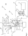
- the figure 1 shows schematically a flap arrangement 210 with a multifunction unit 100 within the scope of the present invention.
- the flap assembly 210 has a flap 201 for a functionally essential element 207, such as. B. a charging socket or a fuel filler pipe, a vehicle 200 on.
- a vehicle as a whole is not shown in the figures for the sake of simplicity.
- the multifunction unit 100 within the scope of the present invention can be used for a flap arrangement 210 of an electric vehicle.
- the flap 201 can be designed, for example, in the form of a charging flap for a charging socket of the electric vehicle.
- the charging socket can be used to charge a traction battery and/or at least one on-board battery of the electric vehicle.
- the multifunction unit 100 within the scope of the present invention can also be used for a flap arrangement 210 of a fuel-powered vehicle or a hybrid vehicle.
- the flap 201 can be designed, for example, in the form of a tank flap for a fuel filler pipe.
- the flap 201 can be driven electrically with the aid of an actuating unit 220, for example.
- the actuating unit 220 can have a drive motor 221, for example in the form of an electric motor, and a gear 222, for example a rotary gear.
- the flap 201 can, for example, be driven to rotate about an axis of rotation D1.
- the flap arrangement 210 is equipped with a multifunction unit 100 within the scope of the invention in order to improve and/or expand the functionality of the flap 201 and to design the operation of the flap 201 with increased safety and to improve customer comfort when operating the flap 201 to increase.
- FIG. 1 shows schematically a multifunction unit 100 within the scope of the invention.
- the multifunction unit 100 is (if required) to provide a closing aid 1 (cf. 4 ) with an advantageous locking function 2 (cf. figure 5 ) and (if required) to provide a burping aid 3 (cf. 6 ) performed on the flap 201.
- the closing aid 1 (cf. 4 ) with an advantageous locking function 2 (cf. figure 5 ) and the burping aid 3 (cf. 6 ) can be provided alternately.
- the locking punch 10 can also be referred to as a pull/push/lock punch.
- the flap arrangement 210 can advantageously have a control unit 208 .
- the control unit 208 can control both the actuating unit 220 and the drive unit 20 .
- the control unit 208 can thus control the actuation of the flap 201 by the actuation unit 220, as a result of which the flap 201 can cover or release the functionally essential element 207.
- the control unit 208 can control the driving of the locking plunger 10 by the drive unit 20, as a result of which the locking plunger 10 can pull the flap 201 closed and lock or unlock it and press it open.
- the invention provides a multifunctional unit 100 with only one drive unit 20, in particular with only one drive motor 21, preferably with only one electric motor, to enable a closing aid 1 (cf. 4 ) with an advantageous locking function 2 (cf. figure 5 ) and a burping aid 3 or an ice-breaking function (cf. 6 ) on the flap 201 to allow.
- the drive unit 20 and the locking plunger 10 are preferably designed in such a way that the locking plunger 10 moves both into a locking position III (cf. figure 5 ) as well as in an unlocked position I (cf. 4 ) is driven using only one drive unit 20, in particular with only one electric motor.
- the drive unit 20 preferably has only one drive motor 21 .
- the flap 201 is actuated with a separate drive motor 221 .
- the drive motor 21 in the drive unit 20 according to the invention can preferably be designed independently of the electric motor 221 in the actuation unit 220 of the flap 201 .
- the flap arrangement 210 can thus be designed with a total of two drive motors 21, 221.
- the locking plunger 10 can be driven in a longitudinally displaceable and/or pivotable or tiltable manner by the drive unit 20 .
- the locking plunger 10 can carry out two different types of movement, namely pivoting or tilting as well as moving up and down.
- a closing aid 1 combined with the advantageous locking function 2 can be provided by the locking plunger 10 .
- the locking plunger 10 can provide a push-up aid or an ice-breaking function.
- the locking plunger 10 can switch between an unlocking position I (cf. 4 ), a closed position II (cf. figure 5 ) and a locking position III (cf. 6 ) relative to the flap 201 are driven to move.
- the locking plunger 10 can be designed with a drive link 11 .
- the drive link 11 can interact with a corresponding drive cam 24 of the drive unit 20 in order to drive the locking plunger 10 between the closed position II and the locked position III and vice versa between the locked position III and the unlocked position I.
- the locking stamp 10 can be loosely accommodated or inserted in the receptacle 203 on the housing 202, in particular without a bearing.
- the locking stamp 10 has freedom of movement for pivoting or tilting as well as moving up and down.
- the locking stamp 10 can come to rest on the side faces of the receptacle 203 .
- no fixed bearings for the locking plunger 10 are provided on the side faces of the receptacle 203 .
- the receptacle 203 forms the only bearing relative to the housing 202 of the flap arrangement 210.
- the receptacle 203 is used only in part to limit and/or help shape the movement of the locking plunger 10.
- the movement of the locking plunger 10 is generated by the drive unit 20.
- the drive link 11 can have a parking bay 11a for the drive cam 24 of the drive unit 20 (see the unlocking position I of the locking stamp 10 in FIG figure 4 ).
- the parking bay 11a can serve to stabilize the unlocking position I of the locking stamp 10.
- the drive link 11 may have a substantially square shape, preferably with rounded corners.
- the drive unit 20 can have a rotary drive, for example in the form of a worm gear 22, 23.
- the drive unit 20 can have a helical worm shaft 22 and a worm wheel 23.
- the operative connection to the drive link 11 on the locking stamp 10 can be established by the drive cam 24 .
- the drive cam 24 can thus rotate on a circular path with the worm wheel 23 .
- a pawl 30 can be provided in the multifunctional unit 100, which can be rotatably mounted on the housing 202 (cf. the bearing L indicated in FIGS Figures 2 to 6 ).
- the spear pawl 30 can be designed to drive unit 20, in particular the drive cam 24, when, in particular longitudinally displaceable and / or pivotable or tiltable, driving the locking stamp 10 to support.
- the pawl 30 can be supported on the housing 202 with the aid of a spring F2, for example.
- FIG 2 schematically shows that an emergency release unit 40 for the locking plunger 10 can be provided in the multifunction unit 100 in order to drive the locking plunger 10 to unlock the flap 201, for example by manually pulling on an emergency release element 41.
- the emergency release unit 40 can be used to deflect the locking stamp 10 to unlock the flap 201 from the locking position III, for example if the electronics fail and/or if no electrical energy is available for the drive unit 20.
- the emergency release unit 40 can thus form a mechanical fallback level for unlocking the flap 201 in an emergency.
- the locking plunger 10 can have a locking lug 12 or a closing hook which can be designed to interact with a complementary counter-locking element 204 on the flap 201 in order to close the flap 201 and/or lock it.
- the locking plunger 10 can have a contoured shoulder 13 which can be designed to cooperate with a complementary contoured cam 205 on the housing 202 in order to help shape the movement of the locking element 10.
- the complementary contour cam 205 can be arranged at an opening in the receptacle 203 of the housing 202 for the locking stamp 10.
- Figures 2 to 6 indicates that the locking plunger 10 is acted upon by a spring F1 in a locking position III relative to the flap 201.
- the spring F1 can be accommodated in a pressure pin.
- At least one sensor element S1 e.g. in the form of a switch, can be provided in the multifunction unit 100, e.g. B. around the Unlocking position I of the locking plunger 10 relative to the flap 201 to detect.
- At least one sensor element S2 e.g. in the form of a switch, can be provided in the multifunction unit 100, e.g. B. to detect the locking position III of the locking plunger 10 relative to the flap 201.
- the figure 3 shows that the locking plunger 10 is deflected when the flap 201 is in the open position, so that the locking lug 12 releases the counter-locking element 204 on the flap 201.
- the flap 201 can be extended unhindered by the locking plunger 10.
- the drive cam 24 is retracted to the far right in the lowest position of the drive link 11 . This position of the drive link 11 was described above as a parking bay 11a for the drive cam 24, which can serve to stabilize the unlocked position I of the locking plunger 10.
- the locking plunger 10 can be designed to be transferred by the flap 201 from the unlocked position I to the closed position II.
- the figure 4 indicate with the arrow downwards how the flap 201 can press the locking stamp 10 from above.
- the locking stamp 10 is moved under the contour cam 205 on the housing 202.
- the drive unit is stationary.
- the rotary drive is not moved and remains in its position.
- the absolute position of the rotary drive remains the same, only the relative position of the drive cam 24 in the drive link 11 changes.
- the drive unit 20 can be designed to convert the locking plunger 10 from the closed position II into the locked position III by rotating a rotary drive 22, 23 in a first direction R1.
- the drive motor 21 rotates the drive cam 24 counterclockwise (first direction R1) in a circular orbit.
- the locking stamp 10 is pulled down. So that the drive cam 24 from the upper position in the drive link 11 (cf. 4 ) to the extreme left end position (cf. figure 5 ) can reach, the pawl 30 is deflected against the spring force of the spring F2.
- the upper spring F1 presses the locking plunger 10 back against the right-hand contour of the housing 202. The flap 20 is caught. If the locking stamp 10 moves against the end stop or switch, the drive motor 21 can be switched off.
- the drive unit 20 can be designed to convert the locking plunger 10 from the locking position III into the unlocking position I by rotating the rotary drive 22, 23 in a second direction R2.
- the drive motor 21 rotates clockwise (second direction R2) and pushes the locking plunger 10 upwards via the pawl 30 .
- the locking stamp 10 runs along the contour cam 205 on the housing 202 and the flap 201 is free. Thus, a parallel movement of upward and deflection movement is generated.
Landscapes
- Engineering & Computer Science (AREA)
- Life Sciences & Earth Sciences (AREA)
- Sustainable Development (AREA)
- Sustainable Energy (AREA)
- Chemical & Material Sciences (AREA)
- Combustion & Propulsion (AREA)
- Transportation (AREA)
- Mechanical Engineering (AREA)
- Lock And Its Accessories (AREA)
- Cooling, Air Intake And Gas Exhaust, And Fuel Tank Arrangements In Propulsion Units (AREA)
Abstract
Die Erfindung betrifft eine Multifunktionseinheit (100) für eine Klappe (201), insbesondere eine Ladeklappe oder eine Tankklappe, eines Fahrzeuges (200), zum Bereitstellen einer Zuziehhilfe (1) mit einer Verriegelungsfunktion (2) und einer Aufstoßhilfe (3) an der Klappe (201), aufweisend: einen Verriegelungsstempel (10) zum Ziehen, zum Verriegeln und/oder zum Drücken an der Klappe (201), welcher in einer Aufnahme (203) an einem Gehäuse (202) für die Klappe (201) bewegbar anordbar ist, und eine Antriebseinheit (20) zum Antreiben des Verriegelungsstempels (10) zum Ziehen, zum Verriegeln und/oder zum Drücken an der Klappe (201).The invention relates to a multifunctional unit (100) for a flap (201), in particular a loading flap or a tank flap, of a vehicle (200) for providing a closing aid (1) with a locking function (2) and an opening aid (3) on the flap (201), having: a locking plunger (10) for pulling, locking and/or pressing on the flap (201), which can be arranged movably in a receptacle (203) on a housing (202) for the flap (201). , and a drive unit (20) for driving the locking plunger (10) for pulling, for locking and/or for pushing on the flap (201).
Description
Die Erfindung betrifft eine Multifunktionseinheit für eine Klappe, insbesondere eine Ladeklappe oder eine Tankklappe, eines Fahrzeuges, vorzugsweise eines Elektrofahrzeuges. Ferner betrifft die Erfindung eine korrespondierende Klappenanordnung mit einer entsprechenden Multifunktionseinheit sowie ein Verfahren zum Betätigen einer entsprechenden Multifunktionseinheit.The invention relates to a multifunctional unit for a flap, in particular a charging flap or a tank flap, of a vehicle, preferably an electric vehicle. Furthermore, the invention relates to a corresponding flap arrangement with a corresponding multifunction unit and a method for actuating a corresponding multifunction unit.
Ladeklappen für Ladesteckdosen bei Elektrofahrzeugen sind grundsätzlich bekannt. Die Ladeklappen können bspw. elektrisch angetrieben werden, um die Betätigung der Ladeklappen zu erleichtern. Moderne Fahrzeuge werden zunehmend mit erweiterten Funktionen bei den Ladeklappen ausgestattet, wie z. B. einer Zuziehfunktion und/oder einer Aufstoßfunktion, bspw. für die Fälle einer Vereisung der Klappe. Die Zuziehfunktion kann mithilfe einer Zuziehhilfevorrichtung bereitgestellt werden. Die Aufstoßfunktion kann mithilfe der gleichen Zuziehhilfevorrichtung oder einer weiteren Aufstoßvorrrichtung bereitgestellt werden. Weiterhin sind Verriegelungsvorrichtungen denkbar, die eine Verriegelungsfunktion an den Ladeklappen bereitstellen können. Nachteilig ist dabei, dass unterschiedliche Funktionen mithilfe von unterschiedlichen Vorrichtungen, zumeist mit mehreren Antriebsmotoren ermöglicht werden.Loading flaps for charging sockets in electric vehicles are known in principle. For example, the tailgates may be electrically powered to facilitate operation of the tailgates. Modern vehicles are increasingly equipped with extended functions in the tailboards, such. B. a closing function and / or an opening function, for example. For the cases of icing of the flap. The closing function can be activated using a closing aid device to be provided. The burping function can be provided using the same cinch mechanism or another burping mechanism. Furthermore, locking devices are conceivable which can provide a locking function on the loading flaps. The disadvantage here is that different functions are made possible with the aid of different devices, usually with a number of drive motors.
Es ist daher Aufgabe der vorliegenden Erfindung, eine verbesserte Multifunktionseinheit für eine Klappe, insbesondere eine Ladeklappe oder eine Tankklappe, eines Fahrzeuges, vorzugsweise eines Elektrofahrzeuges, bereitzustellen. Insbesondere ist es Aufgabe der vorliegenden Erfindung, eine solche Multifunktionseinheit bereitzustellen, die eine vorteilhafte, insbesondere erweiterte, Funktionalität aufweist, die zum Bereitstellen einer Zuziehhilfe mit einer vorteilhaften Verriegelungsfunktion sowie zum Bereitstellen einer Aufstoßhilfe an der Klappe ausgeführt ist, die hierzu nur einen Antriebsmotor benötigt, die einfach aufgebaut ist, die einen kompakten Bauraum aufweist, die leicht zu montieren ist und die zuverlässig im Betrieb ist.It is therefore the object of the present invention to provide an improved multifunctional unit for a flap, in particular a charging flap or a tank flap, of a vehicle, preferably an electric vehicle. In particular, it is the object of the present invention to provide such a multifunctional unit which has an advantageous, in particular extended functionality, which is designed to provide a closing aid with an advantageous locking function and to provide an opening aid on the flap, which only requires a drive motor for this purpose, which has a simple structure, which has a compact installation space, which is easy to assemble and which is reliable in operation.
Die erfindungsgemäße Aufgabe wird gelöst durch eine Multifunktionseinheit für eine Klappe, insbesondere eine Ladeklappe oder eine Tankklappe, eines Fahrzeuges, vorzugsweise eines Elektrofahrzeuges, zum Bereitstellen einer Zuziehhilfe mit einer vorteilhaften Verriegelungsfunktion sowie zum Bereitstellen einer Aufstoßhilfe an der Klappe nach dem unabhängigen Vorrichtungsanspruch. Ferner betrifft die Erfindung eine korrespondierende Klappenanordnung mit einer entsprechenden Multifunktionseinheit nach dem nebengeordneten Vorrichtungsanspruch sowie ein Verfahren zum Betätigen einer entsprechenden Multifunktionseinheit nach dem unabhängigen Verfahrensanspruch. Dabei gelten Merkmale und Details, die im Zusammenhang mit den unterschiedlichen Ausführungsformen und/oder Aspekten der Erfindung beschrieben sind, selbstverständlich auch im Zusammenhang mit den anderen Ausführungsformen und/oder Aspekten und jeweils umgekehrt, sodass bezüglich der Offenbarung zu den einzelnen Ausführungsformen und/oder Aspekten stets wechselseitig Bezug genommen wird bzw. werden kann.The object of the invention is achieved by a multifunctional unit for a flap, in particular a charging flap or a tank flap, of a vehicle, preferably an electric vehicle, for providing a closing aid with an advantageous locking function and for providing an opening aid on the flap according to the independent device claim. Furthermore, the invention relates to a corresponding flap arrangement with a corresponding multifunction unit according to the independent device claim and a method for actuating a corresponding multifunction unit according to the independent method claim. Features and details that are described in connection with the different embodiments and/or aspects of the invention also apply, of course, in connection with the other embodiments and/or aspects and vice versa, so that the disclosure of the individual embodiments and/or aspects is reversed is or can always be mutually referred to.
Gemäß dem ersten Aspekt stellt die Erfindung bereit: Eine Multifunktionseinheit für eine Klappe, insbesondere eine Ladeklappe oder eine Tankklappe, eines Fahrzeuges, zum Bereitstellen einer Zuziehhilfe mit einer Verriegelungsfunktion sowie einer Aufstoßhilfe (auch genannt Eisbrechfunktion) an der Klappe,
aufweisend:
- einen, insbesondere schwenkbar (bzw. kippbar) und/oder längsverschieblich antreibbaren, Verriegelungsstempel (nach Bedarf) zum Ziehen, zum Verriegeln und/oder (nach Bedarf) zum Drücken an der Klappe, welcher in einer Aufnahme an einem Gehäuse für die Klappe bewegbar anordbar ist, und
- eine, insbesondere ausschließlich eine für alle Funktionen der Multifunktionseinheit gemeinsame, Antriebseinheit, die vorzugsweise mit nur einem Antriebsmotor, bspw. nur einem Elektromotor, ausgestaltet sein kann, zum Antreiben des Verriegelungsstempels, sodass der Verriegelungsstempel zum Ziehen, zum Verriegeln und/oder zum Drücken an der Klappe dienen kann.
having:
- a locking plunger (if required) that can be driven in a swiveling (or tiltable) and/or longitudinally displaceable manner for pulling, locking and/or (if required) for pressing on the flap, which can be arranged movably in a receptacle on a housing for the flap is and
- a drive unit, in particular one common for all functions of the multifunctional unit, which can preferably be configured with only one drive motor, e.g. only one electric motor, for driving the locking plunger, so that the locking plunger can be pulled, locked and/or pushed can serve the flap.
Der Verriegelungsstempel kann ebenfalls als ein Zug-/Druck-/Verriegelungsstempel bezeichnet werden.The locking punch can also be referred to as a pull/push/lock punch.
Der Erfindungsgedanke liegt dabei darin, mit nur einer Antriebseinheit, insbesondere mit nur einem Elektromotor, im Rahmen einer einzigen Multifunktionseinheit (nach Bedarf) eine Zuziehhilfe mit einer vorteilhaften Verriegelungsfunktion sowie (nach Bedarf) eine Aufstoßhilfe bzw. eine Eisbrechfunktion an der Klappe zu schaffen. Die Antriebseinheit und der Verriegelungsstempel sind dabei derart ausgeführt, dass der Verriegelungsstempel sowohl in eine Zuziehstellung mit einer Verriegelungsfunktion als auch in eine Entriegelungsstellung mit einer Aufstoßfunktion mithilfe nur einer Antriebseinheit, insbesondere mit nur einem Elektromotor, angetrieben wird. Beim Überführen des Verriegelungsstempels in Verriegelungsstellung wird die Klappe nicht nur zugezogen, sondern weiterhin verriegelt. Beim Überführen des Verriegelungsstempels in die Entriegelungsstellung wird die Klappe zunächst entriegelt und weiterhin aufgestoßen. Die Antriebseinheit weist dabei vorzugsweise nur einen Elektromotor. Die Klappe kann dabei mit einem separaten Elektromotor betätigt werden, bspw. schwenkbar angetrieben werden. Der Elektromotor bei der erfindungsgemäßen Antriebseinheit kann dabei unabhängig von dem Elektromotor bei der Betätigungseinheit der Klappe ausgeführt sein. Der Elektromotor der erfindungsgemäßen Antriebseinheit kann dabei beabstandet zu dem Elektromotor der Betätigungseinheit der Klappe angeordnet sein. Außerdem kann die Multifunktionseinheit einfach aufgebaut werden, einen kompakten Bauraum aufweisen, leicht zu montieren sein und zuverlässig im Betrieb sein.The idea of the invention is to create a closing aid with an advantageous locking function and (if required) an opening aid or an ice-breaking function on the flap with only one drive unit, in particular with only one electric motor, within the framework of a single multifunctional unit. The drive unit and the locking plunger are designed in such a way that the locking plunger is driven both into a closed position with a locking function and into an unlocking position with a push-open function using only one drive unit, in particular with only one electric motor. When the locking plunger is moved into the locking position, the flap is not only pulled closed, but continues to be locked. When the locking plunger is moved into the unlocked position, the flap is first unlocked and then pushed open. The drive unit preferably has only one electric motor. The flap can be actuated with a separate electric motor, for example driven in a swiveling manner. The electric motor in the drive unit according to the invention can be designed independently of the electric motor in the actuation unit of the flap. The electric motor of the drive unit according to the invention can be arranged at a distance from the electric motor of the actuating unit of the flap. In addition, the multifunction unit be simple to set up, have a compact installation space, be easy to assemble and be reliable in operation.
Ferner kann bei einer Multifunktionseinheit vorgesehen sein, dass der Verriegelungsstempel längsverschieblich und/oder schwenkbar (bzw. kippbar) durch die Antriebseinheit antreibbar ist. Dadurch kann ermöglicht werden, dass der Verriegelungsstempel beim Einwirken auf die Klappe zwei unterschiedliche Bewegungsarten durchführen kann, insbesondere bei einer Führung durch ein und dieselbe Antriebskulisse. Auf diese Weise kann durch den Verriegelungsstempel eine Zuziehhilfe bereitgestellt werden, die mit einer vorteilhaften Verriegelungsfunktion kombiniert werden kann. Zugleich kann auf diese Weise eine Aufstoßhilfe bzw. eine Eisbrechfunktion durch den Verriegelungsstempel bereitgestellt werden.Furthermore, in a multifunction unit it can be provided that the locking plunger can be driven by the drive unit in a longitudinally displaceable and/or pivotable (or tiltable) manner. This makes it possible for the locking stamp to be able to carry out two different types of movement when it acts on the flap, in particular when it is guided by one and the same drive link. In this way, the locking plunger can provide a closing aid that can be combined with an advantageous locking function. At the same time, in this way, a push-up aid or an ice-breaking function can be provided by the locking plunger.
Weiterhin kann bei einer Multifunktionseinheit vorgesehen sein, dass der Verriegelungsstempel zwischen einer Entriegelungsstellung, einer Schließstellung und einer Verriegelungsstellung gegenüber der Klappe bewegbar angetrieben wird. Mithilfe der Schließstellung kann eine vorteilhafte erweiterte Funktionalität durch den Verriegelungsstempel ermöglicht werden. Vorzugsweise kann über die Schließstellung eine kombinierte Bewegung, umfassend vorzugweise längsverschiebliche und/oder schwenkbare Bewegung, des Verriegelungsstempels ermöglicht werden, die nach Bedarf zum Ziehen und weiterhin zum Verriegeln der Klappe und/oder nach Bedarf zum Entriegeln und weiterhin zum Drücken an bzw. zum Aufstoßen der Klappe dienen kann. In die Schließstellung kann der Verriegelungsstempel einfachheitshalber durch die Klappe selbst überführt werden, bspw. wenn die Klappe durch einen unabhängigen Antriebsmotor einer separaten Betätigungseinheit abgesenkt wird. Zwischen der Schließstellung und der Verriegelungsstellung sowie zwischen der Verriegelungsstellung und der Entriegelungsstellung kann der Verriegelungsstempel durch die Antriebseinheit, insbesondere mit nur einem Elektromotor, angetrieben werden.Furthermore, it can be provided in a multifunction unit that the locking plunger is driven to be movable between an unlocked position, a closed position and a locked position relative to the flap. With the help of the closed position, an advantageous expanded functionality can be made possible by the locking stamp. A combined movement, preferably comprising a longitudinally displaceable and/or pivoting movement, of the locking plunger can preferably be made possible via the closed position, which can be used to pull and continue to lock the flap and/or to unlock and continue to press on or push open as required can serve the flap. For the sake of simplicity, the locking plunger can be moved into the closed position by the flap itself, for example when the flap is lowered by an independent drive motor of a separate actuating unit. The locking plunger can be driven by the drive unit, in particular with only one electric motor, between the closed position and the locking position and between the locking position and the unlocking position.
Des Weiteren kann bei einer Multifunktionseinheit vorgesehen sein, dass der Verriegelungsstempel eine Antriebskulisse aufweist. Die Antriebskulisse kann dabei mit einem korrespondierenden Antriebsnocken der Antriebseinheit zusammenwirken, um den Verriegelungsstempel zwischen der Schließstellung und der Verriegelungsstellung und umgekehrt zwischen der Verriegelungsstellung und der Entriegelungsstellung anzutreiben. Mithilfe der Antriebskulisse kann einfach und gezielt eine gewünschte, insbesondere kombinierte Bewegung, umfassend vorzugweise längsverschiebliche und/oder schwenkbare Bewegung, zum Ziehen und weiterhin zum Verriegeln und/oder umgekehrt zum Entriegeln und weiterhin zum Drücken an der Klappe ermöglicht werden.Furthermore, it can be provided in a multifunction unit that the locking plunger has a drive link. The drive link can interact with a corresponding drive cam of the drive unit to move the locking plunger between the closed position and the locking position and to drive reversely between the locked position and the unlocked position. With the help of the drive link, a desired, in particular combined movement, preferably comprising a longitudinally displaceable and/or pivoting movement, for pulling and also for locking and/or vice versa for unlocking and also for pressing on the flap can be made possible in a simple and targeted manner.
Zudem kann bei einer Multifunktionseinheit vorgesehen sein, dass der Verriegelungsstempel lose, insbesondere ohne Lager, in der Aufnahme am Gehäuse aufgenommen bzw. eingelegt ist. In der Aufnahme hat der Verriegelungsstempel eine Bewegungsfreiheit zum Vollführen einer kombinierten Bewegung, umfassend vorzugweise längsverschiebliche und/oder schwenkbare Bewegung, wenn der Verriegelungsstempel durch die Antriebseinheit angetrieben wird. Dabei kann der Verriegelungsstempel an den Seitenflächen der Aufnahme zur Auflage kommen. An den Seitenflächen der Aufnahme sind jedoch keine zusätzlichen Lager für den Verriegelungsstempel vorgesehen. Die Aufnahme bildet dabei das einzige Lager gegenüber dem Gehäuse der Klappenanordnung. Die Bewegung des Verriegelungsstempels wird durch die Antriebseinheit erzeugt. Die Aufnahme dient dabei nur zum Teil zum Begrenzen und/oder zum Mitgestalten der Bewegung des Verriegelungsstempels.In addition, in a multifunction unit it can be provided that the locking plunger is received or inserted loosely, in particular without a bearing, in the receptacle on the housing. In the receptacle, the locking plunger has freedom of movement to perform a combined movement, preferably comprising longitudinally displaceable and/or pivoting movement, when the locking plunger is driven by the drive unit. The locking stamp can come to rest on the side surfaces of the receptacle. However, no additional bearings for the locking stamp are provided on the side faces of the receptacle. The recording forms the only bearing relative to the housing of the flap assembly. The movement of the locking plunger is generated by the drive unit. The recording serves only in part to limit and/or help shape the movement of the locking plunger.
Außerdem kann bei einer Multifunktionseinheit vorgesehen sein, dass die Antriebskulisse eine Parkbucht für einen Antriebsnocken der Antriebseinheit, insbesondere in einer Entriegelungsstellung des Verriegelungsstempels, aufweist. Die Parkbucht kann dabei dazu dienen, die Entriegelungsstellung des Verriegelungsstempels zu stabilisieren.In addition, in a multifunction unit it can be provided that the drive link has a parking bay for a drive cam of the drive unit, in particular in an unlocked position of the locking plunger. The parking bay can serve to stabilize the unlocked position of the locking stamp.
Ferner kann bei einer Multifunktionseinheit vorgesehen sein, dass die Antriebskulisse eine im Wesentlichen viereckige Form, vorzugsweise mit abgerundeten Ecken, aufweist. Auf diese Weise kann eine fließende, ruckfreie Bewegung, vorzugsweise mit zwei unterschiedlichen Bewegungsarten, umfassend bspw. eine längsverschiebliche und/oder schwenkbare Bewegung, des Verriegelungsstempels ermöglicht werden.Furthermore, in a multifunction unit it can be provided that the drive link has an essentially square shape, preferably with rounded corners. In this way, a smooth, jerk-free movement, preferably with two different types of movement, including, for example, a longitudinally displaceable and/or pivoting movement, of the locking plunger can be made possible.
Weiterhin kann bei einer Multifunktionseinheit vorgesehen sein, dass die Antriebseinheit einen Rotationsantrieb aufweist. Auf diese Weise kann eine einfache und kostengünstige Antriebseinheit bereitgestellt werden.Furthermore, in a multifunctional unit it can be provided that the drive unit has a rotary drive. In this way, a simple and inexpensive drive unit can be provided.
Vorteilhafterweise kann die Antriebseinheit einen, insbesondere ausschließlich einen, Antriebsmotor, bspw. in der Form eines Elektromotors, aufweisen. Auf diese Weise kann eine kompakte, kostengünstige und einfach montierbare Antriebseinheit bereitgestellt werden.The drive unit can advantageously have one, in particular exclusively one, drive motor, for example in the form of an electric motor. In this way, a compact, cost-effective drive unit that is easy to assemble can be provided.
Vorzugsweise kann die Antriebseinheit ein Schneckengetriebe aufweisen. Ein Schneckengetriebe ist ein einfaches, kostengünstiges sowie einfach montierbares Getriebe. Mithilfe eines solchen Getriebes können relativ hohe Übersetzungen erreicht werden. Zudem ist ein solches Getriebe selbsthemmend. Auf diese Weise können die Endstellung des Verriegelungsstempels stabil gehalten werden. Dabei kann die Antriebseinheit eine schraubenförmige Schneckenwelle und ein Schneckenrad aufweisen.The drive unit can preferably have a worm gear. A worm gear is a simple, inexpensive and easy to assemble gear. Relatively high translations can be achieved with the aid of such a transmission. In addition, such a gear is self-locking. In this way, the end position of the locking stamp can be kept stable. The drive unit can have a helical worm shaft and a worm wheel.
Des Weiteren kann die Antriebseinheit einen Antriebsnocken aufweisen. Durch den Antriebsnocken kann eine Wirkverbindung zu einer Antriebskulisse am Verriegelungsstempel bereitgestellt werden. Der Antriebsnocken kann dabei drehfest mit dem Schneckenrad verbunden sein und mit dem Schneckenrad auf einer Kreisbahn um die Drehachse des Schneckenrades rotieren. Der Antriebsnocken ist dabei mit einem Abstand zu der Drehachse des Schneckenrades an diesem befestigt.Furthermore, the drive unit can have a drive cam. An operative connection to a drive link on the locking stamp can be provided by the drive cam. The drive cam can be non-rotatably connected to the worm wheel and can rotate with the worm wheel on a circular path around the axis of rotation of the worm wheel. The drive cam is attached to the worm wheel at a distance from the axis of rotation of the latter.
Vorteilhafterweise kann der Antriebsnocken zum, insbesondere längsverschieblichen und/oder schwenkbaren, Antreiben des Verriegelungsstempels ausgeführt sein. Hierzu kann der Antriebsnocken mit einer Antriebskulisse am Verriegelungsstempel in einer mechanischen Wirkverbindung stehen. Auf diese Weise kann eine einfache Ausgestaltung der Antriebseinheit und des Verriegelungsstempels ermöglicht werden, die eine gezielt gewählte Bewegung, insbesondere eine kombinierte Bewegung, umfassend vorzugweise längsverschiebliche und/oder schwenkbare Bewegung, zum Ziehen und weiterhin zum Verriegeln und/oder umgekehrt zum Entriegeln und weiterhin zum Drücken an der Klappe des Verriegelungsstempels ermöglicht werden.Advantageously, the drive cam can be designed to drive the locking plunger, in particular to be longitudinally displaceable and/or pivotable. For this purpose, the drive cam can be mechanically operatively connected to a drive link on the locking plunger. In this way, a simple configuration of the drive unit and the locking plunger can be made possible, which enables a specifically selected movement, in particular a combined movement, preferably comprising a longitudinally displaceable and/or pivoting movement, for pulling and further for locking and/or vice versa for unlocking and further for pressing on the flap of the locking stamp.
Zudem kann bei einer Multifunktionseinheit eine Sperrklinke vorgesehen sein, welche drehbar am Gehäuse lagerbar ist, die dazu ausgeführt ist, die Antriebseinheit, insbesondere den Antriebsnocken, beim, insbesondere längsverschieblichen und/oder schwenkbaren, Antreiben des Verriegelungsstempels zu unterstützen. Die Sperrklinke kann bspw. federelastisch am Gehäuse abgestützt sein. Die Sperrklinke kann vorteilhafterweise zum Mitgestalten der Bewegung des Verriegelungsstempels dienen. Vorzugsweise kann die Sperrklinke dazu ausgeführt sein, den Verriegelungsstempel in der Verriegelungsstellung zu halten, insbesondere form- und/oder kraftschlüssig zu halten.In addition, in a multifunction unit, a pawl can be provided, which can be mounted rotatably on the housing and is designed to hold the drive unit, in particular the drive cam, when the, in particular, longitudinally displaceable and/or pivotable to support driving of the locking stamp. The pawl can, for example, be resiliently supported on the housing. The pawl can advantageously serve to help shape the movement of the locking plunger. The pawl can preferably be designed to hold the locking plunger in the locking position, in particular to hold it in a positive and/or non-positive manner.
Außerdem kann bei einer Multifunktionseinheit eine Notentriegelungseinheit für den Verriegelungsstempel vorgesehen sein, um den Verriegelungsstempel zum Entriegeln der Klappe, bspw. durch ein manuelles Ziehen an einem Notentriegelungselement, anzutreiben. Die Notentriegelungseinheit kann dazu dienen, den Verriegelungsstempel zum Entriegeln der Klappe anzutreiben, bspw. wenn die Elektronik versagt und/oder wenn keine elektrische Energie für die Antriebseinheit zur Verfügung steht. Die Notentriegelungseinheit kann dabei eine mechanische Rückfallebene zum Entriegeln der Klappe bilden.In addition, an emergency release unit for the locking plunger can be provided in a multifunctional unit in order to drive the locking plunger to unlock the flap, for example by manually pulling on an emergency release element. The emergency release unit can be used to drive the locking plunger to unlock the flap, for example if the electronics fail and/or if no electrical energy is available for the drive unit. The emergency release unit can form a mechanical fallback level for unlocking the flap.
Ferner kann bei einer Multifunktionseinheit vorgesehen sein, dass der Verriegelungsstempel eine Sperrnase (kann ebenfalls als ein Zuziehhaken bezeichnet werden) aufweist, die dazu ausgeführt ist, mit einem komplementären Gegenrastelement an der Klappe zusammenzuwirken, um die Klappe zuzuziehen und/oder zu verriegeln. Auf diese Weise kann eine konstruktiv einfache sowie effektive Zuziehhilfe mit einer vorteilhaften Verriegelungsfunktion ermöglicht werden.Furthermore, in a multifunction unit it can be provided that the locking plunger has a locking lug (can also be referred to as a closing hook) which is designed to interact with a complementary counter-locking element on the flap in order to close and/or lock the flap. In this way, a structurally simple and effective closing aid with an advantageous locking function can be made possible.
Weiterhin kann bei einer Multifunktionseinheit vorgesehen sein, dass der Verriegelungsstempel eine Konturschulter aufweist, die dazu ausgeführt ist, mit einem komplementären Konturnocken am Gehäuse zusammenzuwirken, um den Verriegelungsstempel bei einer Bewegung zum Ziehen und/oder zum Drücken an der Klappe zu führen. Zudem kann die Konturschulter dazu dienen, den Verriegelungsstempel aus einer Zwischenstellung, wie z. B. einer Schließstellung, in eine Verriegelungsstellung oder in eine Entriegelungsstellung zu führen. Zudem kann die Konturschulter dazu dienen, den Verriegelungsstempel in der Entriegelungsstellung auf Abstand zur Klappe zu halten, um ein Öffnen und/oder Schließen der Klappe bei einer normalen Betätigung der Klappe zu ermöglichen. Der komplementäre Konturnocken kann dabei an einer Öffnung der Aufnahme im Gehäuse angeordnet sein.Furthermore, in a multifunction unit it can be provided that the locking plunger has a contoured shoulder which is designed to interact with a complementary contoured cam on the housing in order to guide the locking plunger during a movement for pulling and/or pushing on the flap. In addition, the contour shoulder can be used to move the locking stamp from an intermediate position, such as. B. a closed position, in a locked position or in an unlocked position. In addition, the contoured shoulder can serve to keep the locking plunger at a distance from the flap in the unlocked position, in order to allow the flap to be opened and/or closed during normal actuation of the flap. The complementary contour cam can be arranged at an opening of the receptacle in the housing.
Des Weiteren kann bei einer Multifunktionseinheit vorgesehen sein, dass der Verriegelungsstempel federelastisch in eine Verriegelungsstellung gegenüber der Klappe beaufschlagt ist, insbesondere durch einen federelastisch vorgespannten Druckstift. Auf diese Weise kann im Rahmen einer Zuziehhilfe einfach und ohne großen konstruktiven Aufwand eine Verriegelungsfunktion bereitgestellt werden.Furthermore, it can be provided in a multifunction unit that the locking plunger is resiliently urged into a locking position relative to the flap, in particular by a resiliently prestressed pressure pin. In this way, as part of a closing aid, a locking function can be provided easily and without great design effort.
Vorteilhafterweise kann bei einer Multifunktionseinheit mindestens ein Sensorelement, insbesondere in Form eines Schalters, vorgesehen sein, um eine Verriegelungsstellung oder eine Entriegelungsstellung des Verriegelungsstempels gegenüber der Klappe zu detektieren. Nach einem weiteren Vorteil kann bei einer Multifunktionseinheit mindestens ein Sensorelement, insbesondere in Form eines Schalters, vorgesehen sein, um eine Verriegelungsstellung des Verriegelungsstempels gegenüber der Klappe zu detektieren. Auf diese Weise kann die Funktionalität der Multifunktionseinheit überwacht werden und ein zuverlässiges Bereitstellen der Funktionen der Multifunktionseinheit sichergestellt werden.Advantageously, at least one sensor element, in particular in the form of a switch, can be provided in a multifunction unit in order to detect a locked position or an unlocked position of the locking plunger relative to the flap. According to a further advantage, at least one sensor element, in particular in the form of a switch, can be provided in a multifunction unit in order to detect a locking position of the locking stamp relative to the flap. In this way, the functionality of the multifunction unit can be monitored and reliable provision of the functions of the multifunction unit can be ensured.
Einfachheitshalber kann der Verriegelungsstempel dazu ausgeführt sein, durch die Klappe aus einer Entriegelungsstellung in eine Schließstellung überführt zu werden. Auf diese Weise kann die Multifunktionseinheit den Umstand nutzen, dass die Klappe durch einen eigenen Antrieb betätigt wird, um die anfängliche Bewegung des Verriegelungsstempels aus der Entriegelungsstellung in die Schließstellung einzuleiten. Nach dem Hinterhaken des Verriegelungsstempels an der Kappe kann der Verriegelungsstempel schließlich die Kappe zuziehen und weiterhin verriegeln.For the sake of simplicity, the locking plunger can be designed to be transferred from an unlocked position into a closed position by the flap. In this way, the multifunction unit can use the fact that the flap is actuated by its own drive in order to initiate the initial movement of the locking plunger from the unlocked position into the closed position. After the locking punch hooks behind the cap, the locking punch can finally pull the cap shut and keep locking.
Vorteilhafterweise kann die Antriebseinheit dazu ausgeführt sein, durch eine Drehung eines Rotationsantriebes in eine erste Richtung den Verriegelungsstempel aus einer Schließstellung in eine Verriegelungsstellung zu überführen. Ferner kann es von Vorteil sein, dass die Antriebseinheit dazu ausgeführt sein kann, durch eine Drehung eines Rotationsantriebes in eine zweite Richtung den Verriegelungsstempel aus einer Verriegelungsstellung in eine Entriegelungsstellung zu überführen. Auf diese Weise kann die Antriebseinheit den Verriegelungsstempel mit wenig elektrischer Leistung, zuverlässig und effektiv antreiben.Advantageously, the drive unit can be designed to convert the locking plunger from a closed position into a locking position by rotating a rotary drive in a first direction. Furthermore, it can be advantageous that the drive unit can be designed to convert the locking plunger from a locking position into an unlocking position by rotating a rotary drive in a second direction. In this way, the drive unit can reliably and effectively drive the locking plunger with little electrical power.
Gemäß dem zweiten Aspekt stellt die Erfindung bereit: Eine Klappenanordnung mit:
- Einer Klappe, insbesondere eine Ladeklappe oder eine Tankklappe, zum Verschließen eines funktionswesentlichen Elementes, insbesondere einer Ladesteckdose oder eines Kraftstoffeinfüllrohres, eines Fahrzeuges, die bewegbar, insbesondere schwenkbar, an einem Gehäuse gelagert ist,
- dem Gehäuse zum Lagern der Klappe,
- einer Betätigungseinheit zum Betätigen der Klappe, und
- einer Multifunktionseinheit zum Bereitstellen einer Zuziehhilfe mit einer Verriegelungsfunktion sowie einer Aufstoßhilfe bzw. einer Eisbrechfunktion an der Klappe, die wie oben beschrieben ausgeführt sein kann.
- A flap, in particular a charging flap or a tank flap, for closing a functionally essential element, in particular a charging socket or a fuel filler pipe, of a vehicle, which is movably, in particular pivotably, mounted on a housing,
- the housing for storing the flap,
- an operating unit for operating the flap, and
- a multifunctional unit for providing a closing aid with a locking function and an opening aid or an ice-breaking function on the flap, which can be designed as described above.
Die Vorteile, die oben im Zusammenhang mit der Multifunktionseinheit beschrieben wurden, können ebenfalls im Zusammenhang mit der erfindungsgemäßen Klappenanordnung erreicht werden. Auf diese Vorteile wird vorliegend vollumfänglich Bezug genommen.The advantages that were described above in connection with the multifunction unit can also be achieved in connection with the flap arrangement according to the invention. Reference is made in full to these advantages here.
Gemäß dem zweiten Aspekt stellt die Erfindung bereit: Ein Verfahren zum Betätigen einer Multifunktionseinheit, die, wie oben beschrieben, ausgeführt sein kann, aufweisend folgende Schritte:
- Schließen der Klappe, um den Verriegelungsstempel aus einer Entriegelungsstellung in eine Schließstellung zu überführen,
- Betätigen der Antriebseinheit in eine erste Richtung, um den Verriegelungsstempel aus einer Schließstellung in eine Verriegelungsstellung zu überführen,
- Betätigen der Antriebseinheit in eine zweite Richtung, um den Verriegelungsstempel aus einer Verriegelungsstellung in eine Entriegelungsstellung zu überführen.
- Closing the flap to move the locking plunger from an unlocked position to a closed position,
- actuating the drive unit in a first direction in order to transfer the locking plunger from a closed position to a locking position,
- Actuate the drive unit in a second direction to move the locking plunger from a locked position to an unlocked position.
Die Vorteile, die oben im Zusammenhang mit der Multifunktionseinheit beschrieben wurden, können ebenfalls im Zusammenhang mit dem erfindungsgemäßen Verfahren erreicht werden. Auf diese Vorteile wird vorliegend vollumfänglich Bezug genommen.The advantages that were described above in connection with the multifunction unit can also be achieved in connection with the method according to the invention. Reference is made in full to these advantages here.
Weitere Vorteile, Merkmale und Einzelheiten der Erfindung ergeben sich aus der nachfolgenden Beschreibung, in der unter Bezugnahme auf die Zeichnungen Ausführungsbeispiele der Erfindung im Einzelnen beschrieben sind. Dabei können die in den Ansprüchen und in der Beschreibung erwähnten Merkmale jeweils einzeln für sich oder in beliebiger Kombination erfindungswesentlich sein. Es zeigen:
- Fig. 1
- eine schematische Ansicht einer Klappenanordnung mit einer Multifunktionseinheit im Rahmen der vorliegenden Erfindung,
- Fig. 2
- eine schematische Schnittdarstellung einer Multifunktionseinheit im Rahmen der vorliegenden Erfindung,
- Fig. 3
- eine schematische Schnittdarstellung einer Multifunktionseinheit mit einem Verriegelungsstempel in einer Entriegelungsstellung,
- Fig. 4
- eine schematische Schnittdarstellung einer Multifunktionseinheit mit einem Verriegelungsstempel in einer Schließstellung,
- Fig. 5
- eine schematische Schnittdarstellung einer Multifunktionseinheit mit einem Verriegelungsstempel in einer Verriegelungsstellung, und
- Fig. 6
- eine schematische Schnittdarstellung einer Multifunktionseinheit mit einem Verriegelungsstempel zwischen einer Schließstellung und einer Entriegelungsstellung.
- 1
- a schematic view of a flap arrangement with a multifunction unit within the scope of the present invention,
- 2
- a schematic sectional view of a multifunctional unit within the scope of the present invention,
- 3
- a schematic sectional view of a multifunction unit with a locking stamp in an unlocked position,
- 4
- a schematic sectional view of a multifunctional unit with a locking stamp in a closed position,
- figure 5
- a schematic sectional view of a multifunction unit with a locking stamp in a locking position, and
- 6
- a schematic sectional view of a multifunction unit with a locking stamp between a closed position and an unlocked position.
In den nachfolgenden Figuren werden für die gleichen technischen Merkmale auch von unterschiedlichen Ausführungsbeispielen die identischen Bezugszeichen verwendet. In der Regel werden die Bezugszeichen von den gleichen Ausführungsbeispielen nur einmal beschrieben.In the following figures, the same reference numbers are used for the same technical features of different exemplary embodiments. As a rule, the reference symbols of the same exemplary embodiments are described only once.
Die
Die Multifunktionseinheit 100 im Rahmen der vorliegenden Erfindung kann für eine Klappenanordnung 210 eines Elektrofahrzeuges genutzt werden. Die Klappe 201 kann dabei bspw. in Form einer Ladeklappe für eine Ladesteckdose des Elektrofahrzeuges ausgeführt sein. Die Ladesteckdose kann dazu genutzt werden, um eine Traktionsbatterie und/oder mindestens eine Bordnetzbatterie des Elektrofahrzeuges aufzuladen.The
Die Multifunktionseinheit 100 im Rahmen der vorliegenden Erfindung kann ebenfalls für eine Klappenanordnung 210 eines treibstoffangetriebenen Fahrzeuges oder eines Hybridfahrzeuges genutzt werden. Die Klappe 201 kann dabei bspw. in Form einer Tankklappe für ein Kraftstoffeinfüllrohr ausgeführt sein.The
Die Klappe 201 kann bspw. mithilfe einer Betätigungseinheit 220 elektrisch angetrieben werden. Dabei kann die Betätigungseinheit 220 einen Antriebsmotor 221, bspw. in der Form eines Elektromotors, und ein Getriebe 222, bspw. ein Rotationsgetriebe, aufweisen. Die Klappe 201 kann bspw. drehbar um eine Drehachse D1 angetrieben werden. Die Klappenanordnung 210 wird mit einer Multifunktionseinheit 100 im Rahmen der Erfindung ausgestattet, um die Funktionsweise der Klappe 201 zu verbessern und/oder zu erweitern, und um den Betrieb der Klappe 201 mit einer erhöhten Sicherheit auszugestalten, und um den Kundenkomfort beim Bedienen der Klappe 201 zu erhöhen.The
Die
Die Multifunktionseinheit 100 weist folgende Elemente auf:
- Einen, insbesondere schwenkbar bzw. kippbar sowie längsverschieblich antreibbaren, Verriegelungsstempel 10 (nach Bedarf) zum Ziehen und weiterhin zum Verriegeln und/oder (nach Bedarf) zum Drücken an
der Klappe 201, welcher ineiner Aufnahme 203 aneinem Gehäuse 202 für dieKlappe 201 bewegbar angeordnet werden kann, und - eine, insbesondere ausschließlich eine für alle Funktionen der Multifunktionseinheit 100 gemeinsame,
Antriebseinheit 20, die vorzugsweise mit nur einem Antriebsmotor 21, bspw. nur einem Elektromotor, ausgestaltet sein kann, zum Antreiben des Verriegelungsstempels 10, wodurch der Verriegelungsstempel 10 nach Bedarf zum Ziehen und weiterhin zum Verriegeln und/oder nach Bedarf zum Drücken an bzw. zu Aufstoßen der Klappe 201 dienen kann.
- A locking plunger 10 (if required) that can be driven in a swiveling or tilting and longitudinally displaceable manner for pulling and also for locking and/or (if required) for pressing on the
flap 201, which is located in areceptacle 203 on ahousing 202 for theflap 201 can be movably arranged, and - one
drive unit 20, in particular one that is exclusively common to all functions ofmultifunction unit 100, which can preferably be configured with only onedrive motor 21, e.g. only one electric motor, for driving lockingplunger 10, whereby lockingplunger 10 can be pulled and continued as required for locking and/or for pressing on or pushing open theflap 201 as required.
Der Verriegelungsstempel 10 kann ebenfalls als ein Zug-/Druck-/Verriegelungsstempel bezeichnet werden.The locking
Die erfindungsgemäße Klappenanordnung 210 kann vorteilhafterweise eine Steuereinheit 208 aufweisen. Die Steuereinheit 208 kann sowohl die Betätigungseinheit 220 als auch die Antriebseinheit 20 ansteuern. Die Steuereinheit 208 kann somit das Betätigen der Klappe 201 durch die Betätigungseinheit 220 ansteuern, wodurch die Klappe 201 das funktionswesentliche Element 207 abdecken oder freigeben kann. Zudem kann die Steuereinheit 208 das Antreiben des Verriegelungsstempels 10 durch die Antriebseinheit 20 ansteuern, wodurch der Verriegelungsstempel 10 die Klappe 201 zuziehen und verriegeln oder entriegeln und aufdrücken kann.The
Die Erfindung stellt eine Multifunktionseinheit 100 mit nur einer Antriebseinheit 20, insbesondere mit nur einem Antriebsmotor 21, vorzugsweise mit nur einem Elektromotor, bereit, um eine Zuziehhilfe 1 (vgl.
Die Antriebseinheit 20 und der Verriegelungsstempel 10 sind vorzugsweise derart ausgeführt, dass der Verriegelungsstempel 10 sowohl in eine Verriegelungsstellung III (vgl.
Beim Überführen (s.
Beim Überführen (s.
Die Antriebseinheit 20 weist dabei vorzugsweise nur einen Antriebsmotor 21 auf. Die Klappe 201 wird mit einem separaten Antriebsmotor 221 betätigt. Der Antriebsmotor 21 bei der erfindungsgemäßen Antriebseinheit 20 kann vorzugsweise unabhängig von dem Elektromotor 221 bei der Betätigungseinheit 220 der Klappe 201 ausgeführt sein. Die Klappenanordnung 210 kann somit insgesamt mit zwei Antriebsmotoren 21, 221 ausgeführt sein.The
Wie die
Wie die
Wie es aus den
Zudem ist es aus den
Außerdem zeigen die
Ferner zeigen die
Aus der
Zudem zeigen die
Außerdem deutet die
Ferner zeigen die
Weiterhin zeigen die
Des Weiteren deuten die
Zudem zeigen die
Außerdem zeigen die
Die
Wie es die
Die
Wie es die
Ferner verdeutlicht die
Die voranstehende Erläuterung der Ausführungsformen beschreibt die vorliegende Erfindung ausschließlich im Rahmen von Beispielen. Selbstverständlich können einzelne Merkmale der Ausführungsformen, sofern technisch sinnvoll, frei miteinander kombiniert werden, ohne den Rahmen der vorliegenden Erfindung zu verlassen.The above explanation of the embodiments describes the present invention exclusively in the context of examples. It goes without saying that individual features of the embodiments can be freely combined with one another, insofar as this makes technical sense, without departing from the scope of the present invention.
- 200200
- Fahrzeugvehicle
- 210210
- Klappenanordnungflap arrangement
- 201201
- Klappeflap
- 202202
- GehäuseHousing
- 203203
- AufnahmeRecording
- 204204
- Gegenrastelementcounter-locking element
- 205205
- Konturnockencontour cam
- 207207
- funktionswesentliches Elementfunctional element
- 208208
- Steuereinheitcontrol unit
- 220220
- Betätigungseinheitoperating unit
- 221221
- Antriebsmotordrive motor
- 222222
- Getriebetransmission
- 100100
- Multifunktionseinheitmultifunction unit
- 1010
- Verriegelungsstempellocking stamp
- 1111
- Antriebskulissedrive link
- 11a11a
- Parkbuchtparking bay
- 1212
- Sperrnaselocking tab
- 1313
- Konturschultercontour shoulder
- 2020
- Antriebseinheitdrive unit
- 2121
- Antriebsmotordrive motor
- 22, 2322, 23
- Schneckengetriebeworm gear
- 2222
- Schneckenwelleworm shaft
- 2323
- Schneckenradworm wheel
- 2424
- Antriebsnockendrive cam
- 3030
- Sperrklinkepawl
- 4040
- Notentriegelungseinheitemergency release unit
- 4141
- Notentriegelungselementemergency release element
- 11
- Zuziehhilfeclosing aid
- 22
- Verriegelungsfunktionlocking function
- 33
- Aufstoßhilfeburping aid
- II
- Entriegelungsstellungunlocked position
- IIII
- Schließstellungclosed position
- IIIIII
- Verriegelungsstellunglocked position
- D1D1
- Drehachseaxis of rotation
- D2D2
- Drehachseaxis of rotation
- F1F1
- FederFeather
- F2F2
- FederFeather
- LL
- Lagercamp
- R1R1
- erste Richtungfirst direction
- R2R2
- zweite Richtungsecond direction
- S1S1
- Sensorelementsensor element
- S2S2
- Sensorelementsensor element
Claims (15)
aufweisend:
having:
dadurch gekennzeichnet,
characterized,
dadurch gekennzeichnet,
characterized,
dadurch gekennzeichnet,
characterized,
dadurch gekennzeichnet,
characterized,
dadurch gekennzeichnet,
characterized,
dadurch gekennzeichnet,
dass eine Notentriegelungseinheit (40) für den Verriegelungsstempel (10) vorgesehen ist, um den Verriegelungsstempel (10) zum Entriegeln der Klappe (201) anzutreiben.Multifunction unit (100) according to any one of the preceding claims,
characterized,
that an emergency release unit (40) for the locking stamp (10) is provided in order to drive the locking stamp (10) to unlock the flap (201).
dadurch gekennzeichnet,
dass der Verriegelungsstempel (10) eine Sperrnase (12) aufweist, die dazu ausgeführt ist, mit einem komplementären Gegenrastelement (204) an der Klappe (201) zusammenzuwirken, um die Klappe (201) zuzuziehen und/oder zu verriegeln.Multifunction unit (100) according to any one of the preceding claims,
characterized,
that the locking plunger (10) has a locking lug (12) which is designed to cooperate with a complementary counter-locking element (204) on the flap (201) in order to close and/or lock the flap (201).
dadurch gekennzeichnet,
dass der Verriegelungsstempel (10) eine Konturschulter (13) aufweist, die dazu ausgeführt ist, mit einem komplementären Konturnocken (205) am Gehäuse (202) zusammenzuwirken, um den Verriegelungsstempel (10) bei einer Bewegung zum Ziehen und/oder zum Drücken an der Klappe (201) zu führen.Multifunction unit (100) according to any one of the preceding claims,
characterized,
that the locking plunger (10) has a contoured shoulder (13) designed to cooperate with a complementary contoured cam (205) on the housing (202) to hold the locking plunger (10) during a pulling and/or pushing movement on the Flap (201) to lead.
dadurch gekennzeichnet,
dass der Verriegelungsstempel (10) federelastisch in eine Verriegelungsstellung (III) gegenüber der Klappe (201) beaufschlagt ist, insbesondere durch einen federelastisch vorgespannten Druckstift.Multifunction unit (100) according to any one of the preceding claims,
characterized,
that the locking plunger (10) is resiliently urged into a locking position (III) relative to the flap (201), in particular by a resiliently prestressed pressure pin.
dadurch gekennzeichnet,
dass mindestens ein Sensorelement (S1), insbesondere in Form eines Schalters, vorgesehen ist, um eine Verriegelungsstellung (III) oder eine Entriegelungsstellung (I) des Verriegelungsstempels (10) gegenüber der Klappe (201) zu detektieren, und/oder dass mindestens ein Sensorelement (S2), insbesondere in Form eines Schalters, vorgesehen ist, um eine Verriegelungsstellung (III) des Verriegelungsstempels (10) gegenüber der Klappe (201) zu detektieren.Multifunction unit (100) according to any one of the preceding claims,
characterized,
that at least one sensor element (S1), in particular in the form of a switch, is provided in order to detect a locked position (III) or an unlocked position (I) of the locking plunger (10) relative to the flap (201), and/or that at least one sensor element (S2), in particular in the form of a switch, is provided in order to detect a locking position (III) of the locking plunger (10) relative to the flap (201).
dadurch gekennzeichnet,
dass der Verriegelungsstempel (10) dazu ausgeführt ist, durch die Klappe (201) aus einer Entriegelungsstellung (I) in eine Schließstellung (II) überführt zu werden.Multifunction unit (100) according to any one of the preceding claims,
characterized,
that the locking plunger (10) is designed to be transferred from an unlocked position (I) into a closed position (II) by the flap (201).
dadurch gekennzeichnet,
characterized,
Applications Claiming Priority (1)
| Application Number | Priority Date | Filing Date | Title |
|---|---|---|---|
| DE102022100688 | 2022-01-13 |
Publications (2)
| Publication Number | Publication Date |
|---|---|
| EP4238798A2 true EP4238798A2 (en) | 2023-09-06 |
| EP4238798A3 EP4238798A3 (en) | 2024-03-20 |
Family
ID=84942806
Family Applications (1)
| Application Number | Title | Priority Date | Filing Date |
|---|---|---|---|
| EP23151250.0A Pending EP4238798A3 (en) | 2022-01-13 | 2023-01-12 | Multifunctional unit for a flap of a vehicle, flap arrangement and a method for actuating the multifunctional unit |
Country Status (2)
| Country | Link |
|---|---|
| EP (1) | EP4238798A3 (en) |
| DE (1) | DE102023100575A1 (en) |
Family Cites Families (7)
| Publication number | Priority date | Publication date | Assignee | Title |
|---|---|---|---|---|
| DE10023382A1 (en) * | 2000-05-12 | 2001-11-15 | Bayerische Motoren Werke Ag | Operation device for vehicle petrol cap; has control unit, which reacts to signals for predetermined operation states and controls operation device to close petrol cap |
| DE10350467B4 (en) * | 2003-10-29 | 2009-07-30 | Schefenacker-Engelmann Spiegel Gmbh | Device for locking and unlocking a fuel filler flap |
| DE202011105059U1 (en) * | 2011-08-31 | 2012-12-03 | Kiekert Aktiengesellschaft | Flap setting device |
| DE102014003056A1 (en) * | 2014-03-10 | 2015-09-10 | GM GLOBAL TECHNOLOGY OPERATION LLC (n. d. Ges. d. Staates Delaware) | Motor vehicle door assembly |
| KR101567246B1 (en) * | 2014-10-17 | 2015-11-06 | 현대자동차주식회사 | Actuator integrated push opener |
| KR102327482B1 (en) * | 2020-09-11 | 2021-11-17 | 대동하이렉스 주식회사 | Switchgear for Fuel Inlet Door of Car |
| DE202021001685U1 (en) * | 2021-05-07 | 2021-06-04 | sauer product GmbH | Vehicle flap with opening and closing device |
-
2023
- 2023-01-12 EP EP23151250.0A patent/EP4238798A3/en active Pending
- 2023-01-12 DE DE102023100575.8A patent/DE102023100575A1/en active Pending
Also Published As
| Publication number | Publication date |
|---|---|
| DE102023100575A1 (en) | 2023-07-13 |
| EP4238798A3 (en) | 2024-03-20 |
Similar Documents
| Publication | Publication Date | Title |
|---|---|---|
| EP3194695B1 (en) | Door handle assembly for a motor vehicle | |
| EP3612695B1 (en) | Lock for a motor vehicle | |
| EP0589158A1 (en) | Remote controlled lock, particularly for motor vehicle doors | |
| DE102012004071A1 (en) | actuator | |
| EP3137709B1 (en) | Closing device for a motor-vehicle hood, and method | |
| EP3612697A1 (en) | Lock for a motor vehicle | |
| DE102013217377A1 (en) | Electric motor vehicle lock with emergency release | |
| WO2012031586A2 (en) | Actuator for a motor vehicle | |
| EP3039211B1 (en) | Electric motor vehicle lock having a spring accumulator | |
| DE60021856T2 (en) | POWERED DOOR LOCKING DEVICE | |
| DE102019116441A1 (en) | Locking device for a motor vehicle | |
| DE102006009835A1 (en) | Electrically-operated automobile door lock has a first actuator and a second actuator operated by an electrical system at different voltage and current | |
| EP4238798A2 (en) | Multifunctional unit for a flap of a vehicle, flap arrangement and a method for actuating the multifunctional unit | |
| DE102017001769B4 (en) | Handle assembly with short-stroke actuation for a vehicle hatch | |
| DE102011006475A1 (en) | Actuator-system for motor vehicle i.e. electric car, has actuator with drive and two latches, which are movable with drive between original position and operation position, where actuator operates two actuation equipments | |
| WO2022127985A1 (en) | Motor vehicle latch | |
| EP1849940B1 (en) | Locking device for a sliding door with means for blocking the door in open position | |
| EP3695078B1 (en) | Motor vehicle lock, in particular liftgate lock | |
| DE102021106877A1 (en) | Locking device for a traction battery in a motor vehicle and battery assembly and disassembly device for a traction battery in a motor vehicle | |
| EP0942123A1 (en) | Device for locking a cover particularly for a hood of a vehicle | |
| DE102010045207A1 (en) | Locking device for vehicle seat of motor car, has locking mechanism whose component is actuatable over gear box by transfer member, and pivotal lever swingable and drivable around pivotal axis | |
| EP3847328A1 (en) | Drive unit for motor-vehicle applications | |
| DE102023100577A1 (en) | Multifunction unit for a flap of a vehicle, flap arrangement and a method for actuating the multifunction unit | |
| WO2019063040A1 (en) | Motor vehicle lock | |
| DE102019215279B4 (en) | Door lock device and vehicle door |
Legal Events
| Date | Code | Title | Description |
|---|---|---|---|
| PUAI | Public reference made under article 153(3) epc to a published international application that has entered the european phase |
Free format text: ORIGINAL CODE: 0009012 |
|
| STAA | Information on the status of an ep patent application or granted ep patent |
Free format text: STATUS: THE APPLICATION HAS BEEN PUBLISHED |
|
| AK | Designated contracting states |
Kind code of ref document: A2 Designated state(s): AL AT BE BG CH CY CZ DE DK EE ES FI FR GB GR HR HU IE IS IT LI LT LU LV MC ME MK MT NL NO PL PT RO RS SE SI SK SM TR |
|
| PUAL | Search report despatched |
Free format text: ORIGINAL CODE: 0009013 |
|
| AK | Designated contracting states |
Kind code of ref document: A3 Designated state(s): AL AT BE BG CH CY CZ DE DK EE ES FI FR GB GR HR HU IE IS IT LI LT LU LV MC ME MK MT NL NO PL PT RO RS SE SI SK SM TR |
|
| RIC1 | Information provided on ipc code assigned before grant |
Ipc: B60K 15/05 20060101AFI20240215BHEP |