EP4238430A1 - Inhalation device and system - Google Patents
Inhalation device and system Download PDFInfo
- Publication number
- EP4238430A1 EP4238430A1 EP21931614.8A EP21931614A EP4238430A1 EP 4238430 A1 EP4238430 A1 EP 4238430A1 EP 21931614 A EP21931614 A EP 21931614A EP 4238430 A1 EP4238430 A1 EP 4238430A1
- Authority
- EP
- European Patent Office
- Prior art keywords
- susceptor
- area
- substrate
- inhaler device
- internal space
- Prior art date
- Legal status (The legal status is an assumption and is not a legal conclusion. Google has not performed a legal analysis and makes no representation as to the accuracy of the status listed.)
- Withdrawn
Links
- 239000000758 substrate Substances 0.000 claims abstract description 142
- 230000005674 electromagnetic induction Effects 0.000 claims abstract description 72
- 239000000443 aerosol Substances 0.000 claims abstract description 58
- 230000006698 induction Effects 0.000 claims abstract description 18
- 238000010438 heat treatment Methods 0.000 claims description 38
- 230000005307 ferromagnetism Effects 0.000 claims description 8
- 239000002994 raw material Substances 0.000 claims description 8
- 229910000831 Steel Inorganic materials 0.000 claims description 4
- 239000010959 steel Substances 0.000 claims description 4
- 230000007246 mechanism Effects 0.000 abstract description 5
- 230000004048 modification Effects 0.000 description 11
- 238000012986 modification Methods 0.000 description 11
- 239000000126 substance Substances 0.000 description 9
- 239000000796 flavoring agent Substances 0.000 description 7
- 235000019634 flavors Nutrition 0.000 description 7
- 230000035515 penetration Effects 0.000 description 7
- 241000208125 Nicotiana Species 0.000 description 6
- 235000002637 Nicotiana tabacum Nutrition 0.000 description 6
- 238000012545 processing Methods 0.000 description 6
- 238000004891 communication Methods 0.000 description 4
- 230000035699 permeability Effects 0.000 description 4
- DNIAPMSPPWPWGF-UHFFFAOYSA-N Propylene glycol Chemical compound CC(O)CO DNIAPMSPPWPWGF-UHFFFAOYSA-N 0.000 description 3
- 230000008859 change Effects 0.000 description 3
- 238000005516 engineering process Methods 0.000 description 3
- 229910052751 metal Inorganic materials 0.000 description 3
- 239000002184 metal Substances 0.000 description 3
- RYGMFSIKBFXOCR-UHFFFAOYSA-N Copper Chemical compound [Cu] RYGMFSIKBFXOCR-UHFFFAOYSA-N 0.000 description 2
- PEDCQBHIVMGVHV-UHFFFAOYSA-N Glycerine Chemical compound OCC(O)CO PEDCQBHIVMGVHV-UHFFFAOYSA-N 0.000 description 2
- XEEYBQQBJWHFJM-UHFFFAOYSA-N Iron Chemical compound [Fe] XEEYBQQBJWHFJM-UHFFFAOYSA-N 0.000 description 2
- PXHVJJICTQNCMI-UHFFFAOYSA-N Nickel Chemical compound [Ni] PXHVJJICTQNCMI-UHFFFAOYSA-N 0.000 description 2
- 230000009471 action Effects 0.000 description 2
- 239000004020 conductor Substances 0.000 description 2
- 229910052802 copper Inorganic materials 0.000 description 2
- 239000010949 copper Substances 0.000 description 2
- 230000006735 deficit Effects 0.000 description 2
- 238000010586 diagram Methods 0.000 description 2
- 230000000694 effects Effects 0.000 description 2
- 230000006870 function Effects 0.000 description 2
- 230000005389 magnetism Effects 0.000 description 2
- 239000000463 material Substances 0.000 description 2
- 238000000034 method Methods 0.000 description 2
- 230000008569 process Effects 0.000 description 2
- 150000005846 sugar alcohols Polymers 0.000 description 2
- NOOLISFMXDJSKH-UTLUCORTSA-N (+)-Neomenthol Chemical compound CC(C)[C@@H]1CC[C@@H](C)C[C@@H]1O NOOLISFMXDJSKH-UTLUCORTSA-N 0.000 description 1
- OKTJSMMVPCPJKN-UHFFFAOYSA-N Carbon Chemical compound [C] OKTJSMMVPCPJKN-UHFFFAOYSA-N 0.000 description 1
- NOOLISFMXDJSKH-UHFFFAOYSA-N DL-menthol Natural products CC(C)C1CCC(C)CC1O NOOLISFMXDJSKH-UHFFFAOYSA-N 0.000 description 1
- 241000196324 Embryophyta Species 0.000 description 1
- HBBGRARXTFLTSG-UHFFFAOYSA-N Lithium ion Chemical compound [Li+] HBBGRARXTFLTSG-UHFFFAOYSA-N 0.000 description 1
- 235000006679 Mentha X verticillata Nutrition 0.000 description 1
- 235000002899 Mentha suaveolens Nutrition 0.000 description 1
- 235000001636 Mentha x rotundifolia Nutrition 0.000 description 1
- 230000005856 abnormality Effects 0.000 description 1
- 230000004075 alteration Effects 0.000 description 1
- 229910052782 aluminium Inorganic materials 0.000 description 1
- XAGFODPZIPBFFR-UHFFFAOYSA-N aluminium Chemical compound [Al] XAGFODPZIPBFFR-UHFFFAOYSA-N 0.000 description 1
- 238000013459 approach Methods 0.000 description 1
- 230000008901 benefit Effects 0.000 description 1
- 230000005540 biological transmission Effects 0.000 description 1
- 239000003990 capacitor Substances 0.000 description 1
- 229910052799 carbon Inorganic materials 0.000 description 1
- 229910017052 cobalt Inorganic materials 0.000 description 1
- 239000010941 cobalt Substances 0.000 description 1
- GUTLYIVDDKVIGB-UHFFFAOYSA-N cobalt atom Chemical compound [Co] GUTLYIVDDKVIGB-UHFFFAOYSA-N 0.000 description 1
- 238000001514 detection method Methods 0.000 description 1
- 239000003814 drug Substances 0.000 description 1
- 230000002349 favourable effect Effects 0.000 description 1
- 235000011187 glycerol Nutrition 0.000 description 1
- 230000001771 impaired effect Effects 0.000 description 1
- 230000006872 improvement Effects 0.000 description 1
- 238000003780 insertion Methods 0.000 description 1
- 230000037431 insertion Effects 0.000 description 1
- 229910052742 iron Inorganic materials 0.000 description 1
- 239000007788 liquid Substances 0.000 description 1
- 229910001416 lithium ion Inorganic materials 0.000 description 1
- 239000000696 magnetic material Substances 0.000 description 1
- 229940041616 menthol Drugs 0.000 description 1
- 239000006199 nebulizer Substances 0.000 description 1
- 229910052759 nickel Inorganic materials 0.000 description 1
- 230000005408 paramagnetism Effects 0.000 description 1
- 239000000843 powder Substances 0.000 description 1
- 230000002441 reversible effect Effects 0.000 description 1
- 239000007787 solid Substances 0.000 description 1
- 229910001220 stainless steel Inorganic materials 0.000 description 1
- 239000010935 stainless steel Substances 0.000 description 1
- 239000013589 supplement Substances 0.000 description 1
- 230000007704 transition Effects 0.000 description 1
- XLYOFNOQVPJJNP-UHFFFAOYSA-N water Substances O XLYOFNOQVPJJNP-UHFFFAOYSA-N 0.000 description 1
- 238000004804 winding Methods 0.000 description 1
- 229910052727 yttrium Inorganic materials 0.000 description 1
Images


Classifications
-
- A—HUMAN NECESSITIES
- A24—TOBACCO; CIGARS; CIGARETTES; SIMULATED SMOKING DEVICES; SMOKERS' REQUISITES
- A24F—SMOKERS' REQUISITES; MATCH BOXES; SIMULATED SMOKING DEVICES
- A24F40/00—Electrically operated smoking devices; Component parts thereof; Manufacture thereof; Maintenance or testing thereof; Charging means specially adapted therefor
- A24F40/40—Constructional details, e.g. connection of cartridges and battery parts
- A24F40/46—Shape or structure of electric heating means
- A24F40/465—Shape or structure of electric heating means specially adapted for induction heating
-
- A—HUMAN NECESSITIES
- A24—TOBACCO; CIGARS; CIGARETTES; SIMULATED SMOKING DEVICES; SMOKERS' REQUISITES
- A24F—SMOKERS' REQUISITES; MATCH BOXES; SIMULATED SMOKING DEVICES
- A24F40/00—Electrically operated smoking devices; Component parts thereof; Manufacture thereof; Maintenance or testing thereof; Charging means specially adapted therefor
- A24F40/20—Devices using solid inhalable precursors
Definitions
- the present invention relates to an inhaler device and a system.
- an inhaler device that generates a substance to be inhaled by a user, such as an electronic tobacco and a nebulizer, is widely used.
- an inhaler device uses a substrate including an aerosol source for generating an aerosol, a flavor source for imparting a flavor component to the generated aerosol, and the like, to generate an aerosol with the imparted flavor component.
- the user is able to taste a flavor by inhaling the aerosol with the imparted flavor component, generated by the inhaler device.
- An action that the user takes to inhale an aerosol is also referred to as puff or puff action below.
- Patent Literature 1 JP 6623175 B2
- Patent Literature 1 describes that an existing coil is used as an electromagnetic induction source but does not describe improvement in the technology of an electromagnetic induction source itself at all.
- the present invention is contemplated in view of the above problem, and it is an object of the present invention to provide a mechanism related to an electromagnetic induction source compatible with an induction heating-type inhaler device.
- an aspect of the present invention provides an inhaler device.
- the inhaler device includes a container capable of accommodating a substrate containing an aerosol source and a susceptor in thermal proximity to the aerosol source in an internal space, and an electromagnetic induction source configured as a solenoid-type coil and disposed so as to surround the container.
- a first part of the electromagnetic induction source located on a front side in a thickness direction orthogonal to a longitudinal direction of the susceptor, and a second part of the electromagnetic induction source, located on a back side in the thickness direction, are disposed in a state shifted from each other in the longitudinal direction of the susceptor such that a ratio of an area of an overlap area in which a first projection area obtained by projecting the first part perpendicularly onto a surface of the susceptor on the front side and a second projection area obtained by projecting the second part perpendicularly onto a surface of the susceptor on the back side overlap in the thickness direction to an area of each of the first projection area and the second projection area ranges from 0% to 90%.
- a shape of the susceptor may be a sheet shape.
- a thickness of the susceptor may range from 10 ⁇ m to 100 ⁇ m.
- the susceptor may be made of a raw material that has ferromagnetism and of which a Curie point falls within a range of temperature that is reachable through induction heating by the electromagnetic induction source.
- the susceptor may be made of steel use stainless (SUS) 430.
- a distribution of the aerosol source may be different between a part of the substrate, proximate to a first non-overlap area that is an area other than the overlap area in the first projection area, or a second non-overlap area that is an area other than the overlap area in the second projection area, and a part of the substrate, proximate to the overlap area.
- the aerosol source may be distributed by a larger amount in the part of the substrate, proximate to the first non-overlap area or the second non-overlap area, than in the part of the substrate, proximate to the overlap area.
- a longitudinal direction of the internal space may substantially coincide with the longitudinal direction of the susceptor, and the first part and the second part may be disposed in a state shifted from each other in the longitudinal direction of the internal space such that, in a state where the susceptor is accommodated in the container in the predetermined state, a ratio of an area of the overlap area to an area of each of the first projection area and the second projection area ranges from 0% to 90%.
- a longitudinal direction of the internal space may substantially differ from the longitudinal direction of the susceptor, and the longitudinal direction of the susceptor may be inclined with respect to the longitudinal direction of the internal space such that, in a state where the susceptor is accommodated in the container in the predetermined state, a ratio of an area of the overlap area to an area of each of the first projection area and the second projection area ranges from 0% to 90%.
- the susceptor may be included in the substrate.
- the container may have an opening, and the substrate may be inserted in the internal space through the opening, a mark may be applied to each of a surface of the inhaler device around the opening and a surface of the substrate, and a position of the mark applied to the surface of the inhaler device around the opening and a position of the mark applied to the surface of the substrate may coincide with each other when the susceptor is accommodated in the container in the predetermined state.
- the container may have an opening, and the substrate may be inserted in the internal space through the opening, and each of the internal space and the substrate may have a shape allowing the substrate to be inserted into the internal space when the susceptor is accommodated in the container in the predetermined state.
- the system includes a substrate containing an aerosol source and including a susceptor in thermal proximity to the aerosol source, and an inhaler device including a container capable of accommodating the substrate in an internal space, and an electromagnetic induction source configured as a solenoid-type coil and disposed so as to surround the container.
- a first part of the electromagnetic induction source located on a front side in a thickness direction orthogonal to a longitudinal direction of the susceptor, and a second part of the electromagnetic induction source, located on a back side in the thickness direction, are disposed in a state shifted from each other in the longitudinal direction of the susceptor such that a ratio of an area of an overlap area in which a first projection area obtained by projecting the first part perpendicularly onto a surface of the susceptor on the front side and a second projection area obtained by projecting the second part perpendicularly onto a surface of the susceptor on the back side overlap in the thickness direction to an area of each of the first projection area and the second projection area ranges from 0% to 90%.
- a mechanism related to an electromagnetic induction source compatible with an induction heating-type inhaler device is provided.
- An inhaler device generates an aerosol by heating a substrate containing an aerosol source by means of induction heating (IH).
- IH induction heating
- FIG. 1 is a schematic diagram that schematically illustrates a configuration example of an inhaler device.
- an inhaler device 100 according to the present configuration example includes a power supply 111, a sensor 112, a notifier 113, a memory 114, a communicator 115, a controller 116, a susceptor 161, an electromagnetic induction source 162, and a holder 140.
- a user inhales in a state where a stick substrate 150 is held by the holder 140.
- structural elements will be sequentially described.
- the power supply 111 stores electric power.
- the power supply 111 supplies electric power to the structural elements of the inhaler device 100.
- the power supply 111 can be a rechargeable battery, such as a lithium ion secondary battery.
- the power supply 111 may be charged when connected to an external power supply with a universal serial bus (USB) cable or the like.
- USB universal serial bus
- the power supply 111 may be charged with a wireless power transmission technology in a state not connected to a power transmitting device.
- only the power supply 111 may be allowed to be removed from the inhaler device 100 or may be allowed to be replaced with a new power supply 111.
- the sensor 112 detects various items of information regarding the inhaler device 100.
- the sensor 112 outputs the detected information to the controller 116.
- the sensor 112 is a pressure sensor, such as a capacitor microphone, a flow sensor, or a temperature sensor.
- the sensor 112 detects a numeric value resulting from user's inhalation, the sensor 112 outputs, to the controller 116, information indicating that the user has inhaled
- the sensor 112 is an input device that receives information input by the user, such as a button and a switch.
- the sensor 112 can include a button for instructions to start or stop generating an aerosol.
- the sensor 112 outputs, to the controller 116, information input by the user.
- the senor 112 is a temperature sensor that detects the temperature of the susceptor 161.
- the temperature sensor detects the temperature of the susceptor 161 in accordance with an electric resistance value of the electromagnetic induction source 162.
- the sensor 112 may detect the temperature of the stick substrate 150 held by the holder 140 in accordance with the temperature of the susceptors 161.
- the notifier 113 notifies the user of information.
- the notifier 113 is a light-emitting device, such as a light emitting diode (LED).
- the notifier 113 emits light in a different pattern of light, for example, when the state of the power supply 111 is a charging required state, when the power supply 111 is in being charged, or when there is an abnormality in the inhaler device 100.
- the pattern of light here is a concept including color, the timing to turn on or off, and the like.
- the notifier 113 may be a display device that displays an image, a sound output device that outputs sound, or a vibration device that vibrates, in addition to or instead of the light-emitting device.
- the notifier 113 may notify information indicating that the user is allowed to inhale.
- the information indicating that the user is allowed to inhale is notified when the temperature of the stick substrate 150 heated by electromagnetic induction reaches a predetermined temperature.
- the memory 114 stores various items of information for the operation of the inhaler device 100.
- the memory 114 is, for example, a non-volatile storage medium, such as a flash memory.
- An example of the pieces of information stored in the memory 114 is information regarding an operating system (OS) of the inhaler device 100, such as the content of control over various structural elements by the controller 116.
- Another example of the items of information stored in the memory 114 is information regarding user's inhalation, such as the number of times of inhalation, inhalation time, and an accumulated inhalation time period.
- the communicator 115 is a communication interface for transmitting and receiving information between the inhaler device 100 and another device.
- the communicator 115 performs communication that conforms with any wired or wireless communication standard.
- a wireless local area network (LAN), a wired LAN, Wi-Fi (registered trademark), Bluetooth (registered trademark), or the like can be adopted as such a communication standard.
- the communicator 115 transmits information regarding user's inhalation to a smartphone in order to display the information regarding user's inhalation on the smartphone.
- the communicator 115 receives new information on the OS from a server in order to update the information on the OS, stored in the memory 114.
- the controller 116 functions as an arithmetic processing unit and a control unit and controls the overall operations in the inhaler device 100 in accordance with various programs.
- the controller 116 includes an electronic circuit, such as a central processing unit (CPU) and a microprocessor.
- the controller 116 may further include a read only memory (ROM) that stores programs and arithmetic parameters to be used, and a random access memory (RAM) that temporarily stores variable parameters as needed.
- ROM read only memory
- RAM random access memory
- Feeding of electric power from the power supply 111 to another structural element, charging of the power supply 111, detection of information by the sensor 112, notification of information by the notifier 113, storing and reading of information by the memory 114, and transmitting and receiving of information by the communicator 115 each are an example of the pieces of processing to be controlled by the controller 116.
- Other pieces of processing to be executed by the inhaler device 100, such as input of information to each structural element and processing based on information output from each structural element, are controlled by the controller 116.
- the holder 140 has an internal space 141.
- the holder 140 holds the stick substrate 150 while accommodating part of the stick substrate 150 in the internal space 141.
- the holder 140 has an opening 142 that allows the internal space 141 to communicate with outside.
- the holder 140 holds the stick substrate 150 that is inserted into the internal space 141 through the opening 142.
- the holder 140 is a tubular body having the opening 142 and a bottom 143 at the ends, and defines the columnar internal space 141.
- the holder 140 can be formed such that the inside diameter is smaller than the outside diameter of the stick substrate 150 in at least part of the tubular body in the height direction of the tubular body.
- the holder 140 can hold the stick substrate 150 such that the stick substrate 150 inserted in the internal space 141 is pressed from the outer circumference.
- the holder 140 also has the function to define a flow path for air passing through the stick substrate 150.
- An air inlet hole that is an inlet for air into the flow path is disposed at, for example, the bottom 143.
- an air outlet hole that is an outlet for air from the flow path is the opening 142.
- the stick substrate 150 is a stick member.
- the stick substrate 150 includes a substrate 151 and an inhalation port 152.
- the substrate 151 includes an aerosol source.
- the aerosol source When the aerosol source is heated, the aerosol source is atomized to generate an aerosol.
- the aerosol source may be, for example, a substance derived from tobacco, such as a processed substance obtained by forming shredded tobacco or tobacco raw material into a granular form, a sheet form, or a powder form.
- the aerosol source may contain a substance not derived from tobacco and made from a plant other than tobacco (for example, mint, a herb, or the like).
- the aerosol source may contain a flavor component, such as menthol.
- the aerosol source may contain a medicine for a patient to inhale.
- the aerosol source is not limited to a solid and may be, for example, a liquid, such as polyhydric alcohol and water.
- a liquid such as polyhydric alcohol and water.
- the polyhydric alcohol include glycerine and propylene glycol.
- At least part of the substrate 151 is accommodated in the internal space 141 of the holder 140 in a state where the stick substrate 150 is held by the holder 140.
- the inhalation port 152 is a member to be held in a mouth of the user during inhalation. At least part of the inhalation port 152 protrudes from the opening 142 in a state where the stick substrate 150 is held by the holder 140.
- the stick substrate 150 further includes the susceptor 161.
- the susceptor 161 produces heat by electromagnetic induction.
- the susceptor 161 is made of a conductive raw material, such as a metal.
- the susceptor 161 is a metal sheet.
- the susceptor 161 is disposed in proximity to the aerosol source. In the example illustrated in FIG. 1 , the susceptor 161 is included in the substrate 151 of the stick substrate 150.
- the susceptor 161 is disposed in thermal proximity to the aerosol source.
- the state where the susceptor 161 is in thermal proximity to the aerosol source means that the susceptor 161 is disposed at a position where heat generated at the susceptor 161 is transferred to the aerosol source.
- the susceptor 161 is included in the substrate 151 together with the aerosol source and surrounded by the aerosol source. With this configuration, heat generated from the susceptor 161 can be efficiently used to heat the aerosol source.
- the susceptor 161 may be untouchable from outside of the stick substrate 150.
- the susceptor 161 may be disposed so as to be embedded in the stick substrate 150.
- the electromagnetic induction source 162 causes the susceptor 161 to produce heat by electromagnetic induction.
- the electromagnetic induction source 162 is, for example, a coiled conductive wire wound around the outer circumference of the holder 140.
- the electromagnetic induction source 162 When the electromagnetic induction source 162 is supplied with alternating current from the power supply 111, the electromagnetic induction source 162 generates a magnetic field.
- the electromagnetic induction source 162 is disposed at a position where the internal space 141 of the holder 140 overlaps the generated magnetic field. Thus, when the magnetic field is generated in a state where the stick substrate 150 is held by the holder 140, eddy current is generated in the susceptor 161, and Joule heat is generated.
- the aerosol source included in the stick substrate 150 is heated and atomized by the Joule heat to generate an aerosol.
- electric power may be supplied to generate an aerosol.
- the temperature of the stick substrate 150 inductively heated by the susceptor 161 and the electromagnetic induction source 162 reaches a predetermined temperature, the user is allowed to inhale. After that, when the sensor 112 detects that the predetermined user input is performed, supply of electric power may be stopped. In another example, in a period during which the sensor 112 detects that the user has inhaled, electric power may be supplied to generate an aerosol.
- a combination of the inhaler device 100 with the stick substrate 150 may be regarded as one system.
- Induction heating is a process of causing a varying magnetic field to enter a conductive physical object to heat the physical object.
- a magnetic field generator that generates a varying magnetic field and a conductive heated object that is heated when exposed to a varying magnetic field relate to induction heating.
- An example of the varying magnetic field is an alternating magnetic field.
- the electromagnetic induction source 162 illustrated in FIG. 1 is an example of the magnetic field generator.
- the susceptor 161 illustrated in FIG. 1 is an example of the heated object.
- the heated object may have magnetism.
- the heated object is further heated by magnetic hysteresis heating.
- Magnetic hysteresis heating is a process of causing a varying magnetic field to enter a magnetic object to heat the object.
- magnetic dipoles contained in the magnetic substance are aligned along the magnetic field. Therefore, when a varying magnetic field enters a magnetic substance, the orientations of the magnetic dipoles change with the varying magnetic field applied. With such reorientation of the magnetic dipoles, heat is generated in the magnetic substance, and the heated object is heated.
- Magnetic hysteresis heating typically occurs at a temperature lower than or equal to a Curie point and does not occur at a temperature exceeding the Curie point.
- a Curie point is a temperature at which a magnetic substance loses its magnetic properties. For example, when the temperature of a heated object having a ferromagnetism at a temperature lower than or equal to a Curie point exceeds the Curie point, a reversible phase transition from ferromagnetism to paramagnetism occurs in the magnetism of the heated object. When the temperature of the heated object exceeds the Curie point, magnetic hysteresis heating does not occur any more, so the rate of increase in temperature reduces.
- the heated object is desirably made of a conductive material.
- the heated object is further desirably made of a material having ferromagnetism. This is because, in the latter case, heating efficiency can be increased by a combination of resistance heating and magnetic hysteresis heating.
- the heated object is made of one or more raw materials selected from a raw material group consisting of aluminum, iron, nickel, cobalt, conductive carbon, copper, stainless steel, and the like.
- induction heating directly heats the susceptor 161 included in the stick substrate 150, it is possible to efficiently heat the substrate as compared to when the stick substrate 150 is heated from the outer circumference or the like with an external heat source.
- the external heat source is inevitably higher in temperature than the stick substrate 150.
- the electromagnetic induction source 162 does not become higher in temperature than the stick substrate 150. Therefore, the temperature of the inhaler device 100 can be maintained at low temperatures as compared to when an external heat source is used, so it is a great benefit in relation to user's safety.
- the electromagnetic induction source 162 generates a varying magnetic field by using electric power supplied from the power supply 111.
- the power supply 111 may be a direct current (DC) power supply.
- the power supply 111 supplies alternating-current power to the electromagnetic induction source 162 via a DC/AC (alternate current) inverter.
- the electromagnetic induction source 162 can generate an alternating magnetic field.
- FIG. 2 is a view that illustrates an example of a physical configuration around the holder 140 according to the present embodiment.
- FIG. 3 is a view that illustrates an example of a physical configuration around the holder 140 according to the present embodiment in a state where the stick substrate 150 is accommodated in the holder 140 in a predetermined state.
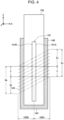
- FIG. 4 is a view that illustrates an example of a cross section taken along the line A-A in FIG. 3 .
- FIG. 5 is a view that illustrates an example of a cross section taken along the line B-B in FIG. 3 .
- the holder 140 is an example of a container capable of accommodating the stick substrate 150 and the susceptor 161 in the internal space 141.
- the electromagnetic induction source 162 is configured as a solenoid-type coil and disposed so as to surround the holder 140.
- the solenoid-type coil here means a coil in which a conductive material, such as copper, is wound with one or more turns, and a winding shape may be a rectangular shape or a circular shape and is not limited.
- the susceptor 161 is formed in a sheet shape.
- the sheet plane of the susceptor 161 expands in a longitudinal direction and in a widthwise direction and is formed so as to define a front and a back in a thickness direction.
- the longitudinal direction, the widthwise direction, and the thickness direction of the susceptor 161 are orthogonal to one another.
- the susceptor 161 is made of a raw material that has ferromagnetism and of which a Curie point falls within a range of temperature that is reachable through induction heating by the electromagnetic induction source 162.
- the susceptor 161 may be made of steel use stainless (SUS) 430.
- SUS steel use stainless
- the Curie point of SUS 430 that is a component of the susceptor 161 falls within a range of temperature that the susceptor 161 is reachable through induction heating by the electromagnetic induction source 162.
- the range of temperature that the susceptor 161 is reachable through induction heating by the electromagnetic induction source 162 ranges from 0°C to 350°C in an example.
- the electromagnetic induction source 162 generates a varying magnetic field in the space surrounded by the coil, that is, the internal space 141, by using electric power supplied from the power supply 111.
- the susceptor 161 is surrounded by the coil. Therefore, the varying magnetic field generated from the electromagnetic induction source 162 enters the susceptor 161 to generate eddy current.
- eddy current in a direction opposite to a direction in which current flows through the electromagnetic induction source 162 flows in the cross section of the susceptor 161.
- ⁇ current penetration depth [mm].
- ⁇ specific resistance [ ⁇ m].
- ⁇ r relative permeability.
- f heating frequency [Hz].
- a Z-axis direction illustrated in FIGS. 2 to 5 is the longitudinal direction of the internal space 141 and is a direction in which the stick substrate 150 is inserted and removed.
- a direction in which the stick substrate 150 is removed is positive and a direction in which the stick substrate 150 is inserted is negative.
- part of the electromagnetic induction source 162 located on the front side of the susceptor 161 and part of the electromagnetic induction source 162 located on the back side of the susceptor 161 are disposed in a state shifted in the Z-axis direction across the holder 140.
- An X-axis direction is a direction in which a shift of the electromagnetic induction source 162 in the Z-axis direction across the holder 140 is largest.
- an X-axis positive direction is also referred to as front side
- an X-axis negative direction is also referred to as back side.
- a Y-axis direction is a direction orthogonal to the X-axis direction and the Z-axis direction.
- the Y-axis direction is a direction in which a shift of the electromagnetic induction source 162 in the Z-axis direction across the holder 140 is smallest.
- the longitudinal direction of the susceptor 161 substantially coincides with the Z-axis direction
- the widthwise direction of the susceptor 161 substantially coincides with the Y-axis direction
- the thickness direction of the susceptor 161 substantially coincides with the X-axis direction.
- the distal end of the stick substrate 150 reaches the bottom 143 of the holder 140.
- This state is a state where the susceptor 161 (that is, the stick substrate 150 including the susceptor 161) is accommodated in (held by) the holder 140 in the predetermined state. It is assumed that the phrase "substantially coincides" includes not only complete coincidence but also a state shifted by smaller than a few degrees.
- a first part 162A and a second part 162B of the electromagnetic induction source 162 are disposed in a state shifted from each other in the longitudinal direction of the susceptor 161 such that the ratio of the area of an overlap area Y to the area of each of a first projection area X A and a second projection area X B ranges from 0% to 90%.
- the electromagnetic induction source 162 is disposed such that each of Y/X A ⁇ 100% and Y/X B ⁇ 100% ranges from 0% to 90%, that is, the first part 162A and the second part 162B are in a state shifted from each other in the Z-axis direction. With this configuration, as will be described below, the susceptor 161 can be efficiently heated.
- the first projection area X A is an area obtained by projecting the first part 162A of the electromagnetic induction source 162, located on the front side of the susceptor 161, perpendicularly onto the surface 161A of the susceptor 161 on the front side.
- the first projection area X A is an area surrounded by a line obtained by projecting both ends of the first part 162A in the Z-axis direction perpendicularly onto the surface 161A of the susceptor 161 on the front side.
- the first projection area X A includes not only an area obtained by actually projecting a coil but also an area placed between parts of the coil.
- the second projection area X B is an area obtained by projecting the second part 162B of the electromagnetic induction source 162, located on the back side of the susceptor 161, perpendicularly onto the surface 161B of the susceptor 161 on the back side.
- the second projection area X B is an area surrounded by a line obtained by projecting both ends of the second part 162B in the Z-axis direction perpendicularly onto the surface 161B of the susceptor 161 on the back side.
- the second projection area X B includes not only an area obtained by actually projecting a coil but also an area placed between parts of the coil.
- the overlap area Y is an area in which the first projection area X A and the second projection area X B overlap in the thickness direction.
- first projection area X A an area other than the overlap area Y is also referred to as first non-overlap area Z A .
- second non-overlap area Z B an area other than the overlap area Y is also referred to as second non-overlap area Z B .
- the electromagnetic induction source 162 is present on both front and back sides of the susceptor 161. Therefore, on both front and back sides of the susceptor 161, eddy current 20 flows in a direction opposite to a direction in which current 10 flows through the electromagnetic induction source 162. Therefore, in the overlap area Y, eddy currents respectively flowing on the front and back sides of the susceptor 161 can interfere to cancel out each other. As a result, current is hard to flow in the cross section of the susceptor 161, and heating is impaired.
- the electromagnetic induction source 162 is present only on one of the front and back sides of the susceptor 161.
- eddy current 20 flows in a direction opposite to a direction in which current 10 flows through the electromagnetic induction source 162. Therefore, in these areas, eddy currents on the front and back sides do not interfere with each other, so the susceptor 161 is suitably heated without impairment.
- the specific resistance ⁇ of a metal increases with an increase in temperature.
- the current penetration depth ⁇ increases with an increase in specific resistance ⁇ .
- the relative permeability ⁇ r reduces as the temperature increases and approaches a Curie point, and the relative permeability ⁇ r becomes one when the temperature exceeds the Curie point. Therefore, through the expression (1), the current penetration depth ⁇ increases as the relative permeability ⁇ r reduces. In this way, the current penetration depth ⁇ of the eddy current 20 increases with an increase in temperature. Since interference of the eddy current 20 flowing on each of the front and back sides of the susceptor 161 increases as the current penetration depth ⁇ increases, it is difficult for the susceptor 161 having a thin thickness to heat.
- parts of the electromagnetic induction source 162 respectively located on the front and back sides of the susceptor 161 are disposed in a state shifted from each other in the longitudinal direction of the susceptor 161.
- interference of eddy current flowing through each of the front and back sides of the susceptor 161 is reduced, so efficient heating can be implemented.
- the ratio of the area of the overlap area Y to the area of each of the first projection area X A and the second projection area X B is desirably smaller the better for the above-described reason.
- the ratio of the area of the overlap area Y to the area of each of the first projection area X A and the second projection area X B ranges from 0% to 60%.
- the current penetration depth ⁇ reaches 10 [ ⁇ m] to 200 [ ⁇ m] within the range of temperature that the susceptor 161 is reachable through induction heating by the electromagnetic induction source 162.
- the thickness of the susceptor 161 may range from 10 [ ⁇ m] to 100 [ ⁇ m].
- a distribution of an aerosol source may be different between a part of the stick substrate 150, proximate to the first non-overlap area Z A or the second non-overlap area Z B , and a part of the stick substrate 150, proximate to the overlap area Y.
- the temperature more easily increases in the first non-overlap area Z A and the second non-overlap area Z B than in the overlap area Y, and this tendency is further remarkable in a range over the Curie point.
- a part of the stick substrate 150, proximate to the first non-overlap area Z A or the second non-overlap area Z B more easily increases in temperature, while a part of the stick substrate 150, proximate to the overlap area Y, is hard to increase in temperature.
- proximity means to be located at the same position or a close position in the longitudinal direction of the stick substrate 150.
- a larger amount of aerosol source may be distributed to a part of the stick substrate 150, proximate to the first non-overlap area Z A or the second non-overlap area Z B , than to a part of the stick substrate 150, proximate to the overlap area Y.
- a larger amount of aerosol source is distributed to a part of the stick substrate 150, proximate to the first non-overlap area Z A or the second non-overlap area Z B , that is, a part of the stick substrate 150, that more easily increases in temperature, it is possible to generate a large amount of aerosol.
- parts of the electromagnetic induction source 162 respectively located on the front and back sides of the susceptor 161 (that is, located on the positive side and the negative side in the Y-axis direction), are disposed in a state where parts of the electromagnetic induction source 162 have substantially no shift in the Z-axis direction across the holder 140. Therefore, the ratio of the area of the overlap area Y to the area of each of the first projection area X A and the second projection area X B is substantially 100%, so it can be difficult to perform efficient heating.
- FIG. 6 is a view for illustrating a first modification.
- FIG. 6 illustrates an external appearance of the inhaler device 100 and the stick substrate 150 in a state where the stick substrate 150 is accommodated in the holder 140 in the predetermined state.
- marks 31, 32 may be respectively applied to the surface of the inhaler device 100 around the opening 142 and the surface of the stick substrate 150.
- the position of the mark 31 applied to the surface of the inhaler device 100 around the opening 142 and the position of the mark 32 applied to the surface of the stick substrate 150 may coincide with each other when the stick substrate 150 is accommodated in the holder 140 in the predetermined state.
- the user is prompted to insert the stick substrate 150 into the internal space 141 such that, as illustrated in FIG.
- the mark 31 that is an arrow and the mark 32 that is an arrow are opposed to each other.
- the stick substrate 150 is accommodated in the holder 140 in the predetermined state as illustrated in FIGS. 3 to 5 .
- the user is able to easily implement a state where the stick substrate 150 is accommodated in the holder 140 in the predetermined state by just adjusting the position of the mark 31 with the position of the mark 32 and inserting the stick substrate 150 into the internal space 141.
- FIG. 7 is a view for illustrating another example of the first modification.
- FIG. 7 illustrates a cross section around the holder 140 in a state where the stick substrate 150 is accommodated in the holder 140 in a predetermined state.
- the internal space 141 and the stick substrate 150 may have such a shape that the stick substrate 150 can be inserted in the internal space 141 when the stick substrate 150 is accommodated in the holder 140 in the predetermined state.
- the sectional shape of each of the internal space 141 and the stick substrate 150 is a rectangular shape having long sides and short sides, and the stick substrate 150 is allowed to be inserted only in a state where the long sides and the short sides of the respective sectional shapes coincide with each other.
- the short sides of the sectional shape of the internal space 141 are formed in the X-axis direction
- the long sides of the sectional shape of the internal space 141 are formed in the Y-axis direction.
- the susceptor 161 is disposed in the stick substrate 150 such that the thickness direction of the susceptor 161 is parallel to the widthwise direction of the cross section of the stick substrate 150. Therefore, as illustrated in FIG. 7 , when the stick substrate 150 is inserted in the internal space 141, the thickness direction of the susceptor 161 substantially coincides with the X-axis direction. In other words, the stick substrate 150 is accommodated in the holder 140 in a predetermined state.
- the user is able to easily implement a state where the stick substrate 150 is accommodated in the holder 140 in a predetermined state by just inserting the stick substrate 150 into the internal space 141.
- each of the holder 140 and the stick substrate 150 is not limited to a rectangular shape illustrated in FIG. 7 and may be, for example, an elliptical shape or the like.
- the present invention is not limited to this example.
- the longitudinal direction of the internal space 141 and the longitudinal direction of the susceptor 161 may be substantially different from each other.
- the phrase "substantially different" means a state shifted by larger than or equal to a few degrees. This example will be described with reference to FIG. 8 .
- FIG. 8 is a view for illustrating a second modification.
- FIG. 8 illustrates a cross section around the holder 140 in a state where the stick substrate 150 is accommodated in the holder 140 in a predetermined state.
- the longitudinal direction of the susceptor 161 may be inclined with respect to the longitudinal direction of the stick substrate 150.
- the longitudinal direction of the susceptor 161 may be inclined with respect to the longitudinal direction of the internal space 141 (that is, the Z-axis direction).
- the longitudinal direction of the susceptor 161 may be inclined with respect to the longitudinal direction of the internal space 141 such that the ratio of the area of the overlap area Y to the area of each of the first projection area X A and the second projection area X B ranges from 0% to 90%.
- parts of the electromagnetic induction source 162, respectively located on the front and back sides of the susceptor 161 are disposed in a state shifted from each other in the longitudinal direction of the susceptor 161.
- interference of eddy current flowing through each of the front and back sides of the susceptor 161 is reduced, so efficient heating can be implemented.
- the predetermined state in the present modification means a state where the widthwise direction of the susceptor 161 substantially coincides with the Y-axis direction and the distal end of the stick substrate 150 reaches the bottom 143 of the holder 140.
- the susceptor 161 has a sheet shape and the sectional shape is a rectangular shape
- the present invention is not limited to this example.
- the sectional shape of the susceptor 161 may be any shape, such as a rounded corner rectangular shape, a square shape, a circular shape, and an elliptical shape.
- the surface of the susceptor 161 may be flat or may change like waving or the like.
- the susceptor 161 can be disposed at any position at which the susceptor 161 is in thermal proximity to the aerosol source.
- the susceptor 161 may be formed in a blade shape and disposed so as to protrude from the bottom 143 of the holder 140 into the internal space 141.
- the stick substrate 150 is inserted into the holder 140, the stick substrate 150 is inserted such that the blade-shaped susceptor 161 sticks into the substrate 151 from an end of the stick substrate 150 in an insertion direction.
- the susceptor 161 is disposed in the internal space 141 such that the holder 140 accommodates the susceptor 161 constantly in a predetermined state.
Landscapes
- Container, Conveyance, Adherence, Positioning, Of Wafer (AREA)
- Medical Preparation Storing Or Oral Administration Devices (AREA)
Abstract
Description
- The present invention relates to an inhaler device and a system.
- An inhaler device that generates a substance to be inhaled by a user, such as an electronic tobacco and a nebulizer, is widely used. For example, an inhaler device uses a substrate including an aerosol source for generating an aerosol, a flavor source for imparting a flavor component to the generated aerosol, and the like, to generate an aerosol with the imparted flavor component. The user is able to taste a flavor by inhaling the aerosol with the imparted flavor component, generated by the inhaler device. An action that the user takes to inhale an aerosol is also referred to as puff or puff action below.
- An inhaler device of a type using an external heat source, such as a heating blade, has been the mainstream so far. However, in recent years, an induction heating-type inhaler device that generates an aerosol by inductively heating a susceptor with a solenoid-type coil as an electromagnetic induction source, as described in Patent Literature 1 below, has become a focus of attention.
- Patent Literature 1:
JP 6623175 B2 - However, Patent Literature 1 describes that an existing coil is used as an electromagnetic induction source but does not describe improvement in the technology of an electromagnetic induction source itself at all.
- The present invention is contemplated in view of the above problem, and it is an object of the present invention to provide a mechanism related to an electromagnetic induction source compatible with an induction heating-type inhaler device.
- To solve the above problem, an aspect of the present invention provides an inhaler device. The inhaler device includes a container capable of accommodating a substrate containing an aerosol source and a susceptor in thermal proximity to the aerosol source in an internal space, and an electromagnetic induction source configured as a solenoid-type coil and disposed so as to surround the container. In a state where the susceptor is accommodated in the container in a predetermined state, a first part of the electromagnetic induction source, located on a front side in a thickness direction orthogonal to a longitudinal direction of the susceptor, and a second part of the electromagnetic induction source, located on a back side in the thickness direction, are disposed in a state shifted from each other in the longitudinal direction of the susceptor such that a ratio of an area of an overlap area in which a first projection area obtained by projecting the first part perpendicularly onto a surface of the susceptor on the front side and a second projection area obtained by projecting the second part perpendicularly onto a surface of the susceptor on the back side overlap in the thickness direction to an area of each of the first projection area and the second projection area ranges from 0% to 90%.
- A shape of the susceptor may be a sheet shape.
- A thickness of the susceptor may range from 10 µm to 100 µm.
- The susceptor may be made of a raw material that has ferromagnetism and of which a Curie point falls within a range of temperature that is reachable through induction heating by the electromagnetic induction source.
- The susceptor may be made of steel use stainless (SUS) 430.
- A distribution of the aerosol source may be different between a part of the substrate, proximate to a first non-overlap area that is an area other than the overlap area in the first projection area, or a second non-overlap area that is an area other than the overlap area in the second projection area, and a part of the substrate, proximate to the overlap area.
- The aerosol source may be distributed by a larger amount in the part of the substrate, proximate to the first non-overlap area or the second non-overlap area, than in the part of the substrate, proximate to the overlap area.
- A longitudinal direction of the internal space may substantially coincide with the longitudinal direction of the susceptor, and the first part and the second part may be disposed in a state shifted from each other in the longitudinal direction of the internal space such that, in a state where the susceptor is accommodated in the container in the predetermined state, a ratio of an area of the overlap area to an area of each of the first projection area and the second projection area ranges from 0% to 90%.
- A longitudinal direction of the internal space may substantially differ from the longitudinal direction of the susceptor, and the longitudinal direction of the susceptor may be inclined with respect to the longitudinal direction of the internal space such that, in a state where the susceptor is accommodated in the container in the predetermined state, a ratio of an area of the overlap area to an area of each of the first projection area and the second projection area ranges from 0% to 90%.
- The susceptor may be included in the substrate.
- The container may have an opening, and the substrate may be inserted in the internal space through the opening, a mark may be applied to each of a surface of the inhaler device around the opening and a surface of the substrate, and a position of the mark applied to the surface of the inhaler device around the opening and a position of the mark applied to the surface of the substrate may coincide with each other when the susceptor is accommodated in the container in the predetermined state.
- The container may have an opening, and the substrate may be inserted in the internal space through the opening, and each of the internal space and the substrate may have a shape allowing the substrate to be inserted into the internal space when the susceptor is accommodated in the container in the predetermined state.
- To solve the above problem, another aspect of the present invention provides a system. The system includes a substrate containing an aerosol source and including a susceptor in thermal proximity to the aerosol source, and an inhaler device including a container capable of accommodating the substrate in an internal space, and an electromagnetic induction source configured as a solenoid-type coil and disposed so as to surround the container. In a state where the substrate is accommodated in the container in a predetermined state, a first part of the electromagnetic induction source, located on a front side in a thickness direction orthogonal to a longitudinal direction of the susceptor, and a second part of the electromagnetic induction source, located on a back side in the thickness direction, are disposed in a state shifted from each other in the longitudinal direction of the susceptor such that a ratio of an area of an overlap area in which a first projection area obtained by projecting the first part perpendicularly onto a surface of the susceptor on the front side and a second projection area obtained by projecting the second part perpendicularly onto a surface of the susceptor on the back side overlap in the thickness direction to an area of each of the first projection area and the second projection area ranges from 0% to 90%.
- As described above, according to the present invention, a mechanism related to an electromagnetic induction source compatible with an induction heating-type inhaler device is provided.
-
- [
FIG. 1] FIG. 1 is a schematic diagram that schematically illustrates a configuration example of an inhaler device. - [
FIG. 2] FIG. 2 is a view that illustrates an example of a physical configuration around a holder according to a present embodiment. - [
FIG. 3] FIG. 3 is a view that illustrates an example of a physical configuration around the holder according to the present embodiment in a state where a stick substrate is accommodated in the holder in a predetermined state. - [
FIG. 4] FIG. 4 is a view that illustrates an example of a cross section taken along the line A-A inFIG. 3 . - [
FIG. 5] FIG. 5 is a view that illustrates an example of a cross section taken along the line B-B inFIG. 3 . - [
FIG. 6] FIG. 6 is a view for illustrating a first modification. - [
FIG. 7] FIG. 7 is a view for illustrating another example of the first modification. - [
FIG. 8] FIG. 8 is a view for illustrating a second modification. - Hereinafter, a preferred embodiment of the present invention will be described in detail with reference to the attached drawings. In the specification and the drawings, like reference signs denote structural elements having substantially the same functional configurations, and the description will not be repeated.
- An inhaler device according to the present configuration example generates an aerosol by heating a substrate containing an aerosol source by means of induction heating (IH). Hereinafter, the present configuration example will be described with reference to
FIG. 1 . -
FIG. 1 is a schematic diagram that schematically illustrates a configuration example of an inhaler device. As illustrated inFIG. 1 , aninhaler device 100 according to the present configuration example includes apower supply 111, asensor 112, anotifier 113, amemory 114, acommunicator 115, acontroller 116, asusceptor 161, anelectromagnetic induction source 162, and aholder 140. A user inhales in a state where astick substrate 150 is held by theholder 140. Hereinafter, structural elements will be sequentially described. - The
power supply 111 stores electric power. Thepower supply 111 supplies electric power to the structural elements of theinhaler device 100. Thepower supply 111 can be a rechargeable battery, such as a lithium ion secondary battery. Thepower supply 111 may be charged when connected to an external power supply with a universal serial bus (USB) cable or the like. Alternatively, thepower supply 111 may be charged with a wireless power transmission technology in a state not connected to a power transmitting device. Other than the above, only thepower supply 111 may be allowed to be removed from theinhaler device 100 or may be allowed to be replaced with anew power supply 111. - The
sensor 112 detects various items of information regarding theinhaler device 100. Thesensor 112 outputs the detected information to thecontroller 116. In an example, thesensor 112 is a pressure sensor, such as a capacitor microphone, a flow sensor, or a temperature sensor. When thesensor 112 detects a numeric value resulting from user's inhalation, thesensor 112 outputs, to thecontroller 116, information indicating that the user has inhaled In another example, thesensor 112 is an input device that receives information input by the user, such as a button and a switch. Particularly, thesensor 112 can include a button for instructions to start or stop generating an aerosol. Thesensor 112 outputs, to thecontroller 116, information input by the user. In another example, thesensor 112 is a temperature sensor that detects the temperature of thesusceptor 161. The temperature sensor, for example, detects the temperature of thesusceptor 161 in accordance with an electric resistance value of theelectromagnetic induction source 162. Thesensor 112 may detect the temperature of thestick substrate 150 held by theholder 140 in accordance with the temperature of thesusceptors 161. - The
notifier 113 notifies the user of information. In an example, thenotifier 113 is a light-emitting device, such as a light emitting diode (LED). In this case, thenotifier 113 emits light in a different pattern of light, for example, when the state of thepower supply 111 is a charging required state, when thepower supply 111 is in being charged, or when there is an abnormality in theinhaler device 100. The pattern of light here is a concept including color, the timing to turn on or off, and the like. Thenotifier 113 may be a display device that displays an image, a sound output device that outputs sound, or a vibration device that vibrates, in addition to or instead of the light-emitting device. Other than the above, thenotifier 113 may notify information indicating that the user is allowed to inhale. The information indicating that the user is allowed to inhale is notified when the temperature of thestick substrate 150 heated by electromagnetic induction reaches a predetermined temperature. - The
memory 114 stores various items of information for the operation of theinhaler device 100. Thememory 114 is, for example, a non-volatile storage medium, such as a flash memory. An example of the pieces of information stored in thememory 114 is information regarding an operating system (OS) of theinhaler device 100, such as the content of control over various structural elements by thecontroller 116. Another example of the items of information stored in thememory 114 is information regarding user's inhalation, such as the number of times of inhalation, inhalation time, and an accumulated inhalation time period. - The
communicator 115 is a communication interface for transmitting and receiving information between theinhaler device 100 and another device. Thecommunicator 115 performs communication that conforms with any wired or wireless communication standard. A wireless local area network (LAN), a wired LAN, Wi-Fi (registered trademark), Bluetooth (registered trademark), or the like can be adopted as such a communication standard. In an example, thecommunicator 115 transmits information regarding user's inhalation to a smartphone in order to display the information regarding user's inhalation on the smartphone. In another example, thecommunicator 115 receives new information on the OS from a server in order to update the information on the OS, stored in thememory 114. - The
controller 116 functions as an arithmetic processing unit and a control unit and controls the overall operations in theinhaler device 100 in accordance with various programs. Thecontroller 116 includes an electronic circuit, such as a central processing unit (CPU) and a microprocessor. Thecontroller 116 may further include a read only memory (ROM) that stores programs and arithmetic parameters to be used, and a random access memory (RAM) that temporarily stores variable parameters as needed. Theinhaler device 100 executes various pieces of processing in accordance with control by thecontroller 116. Feeding of electric power from thepower supply 111 to another structural element, charging of thepower supply 111, detection of information by thesensor 112, notification of information by thenotifier 113, storing and reading of information by thememory 114, and transmitting and receiving of information by thecommunicator 115 each are an example of the pieces of processing to be controlled by thecontroller 116. Other pieces of processing to be executed by theinhaler device 100, such as input of information to each structural element and processing based on information output from each structural element, are controlled by thecontroller 116. - The
holder 140 has aninternal space 141. Theholder 140 holds thestick substrate 150 while accommodating part of thestick substrate 150 in theinternal space 141. Theholder 140 has anopening 142 that allows theinternal space 141 to communicate with outside. Theholder 140 holds thestick substrate 150 that is inserted into theinternal space 141 through theopening 142. For example, theholder 140 is a tubular body having theopening 142 and a bottom 143 at the ends, and defines the columnarinternal space 141. Theholder 140 can be formed such that the inside diameter is smaller than the outside diameter of thestick substrate 150 in at least part of the tubular body in the height direction of the tubular body. Theholder 140 can hold thestick substrate 150 such that thestick substrate 150 inserted in theinternal space 141 is pressed from the outer circumference. Theholder 140 also has the function to define a flow path for air passing through thestick substrate 150. An air inlet hole that is an inlet for air into the flow path is disposed at, for example, the bottom 143. On the other hand, an air outlet hole that is an outlet for air from the flow path is theopening 142. - The
stick substrate 150 is a stick member. Thestick substrate 150 includes asubstrate 151 and aninhalation port 152. - The
substrate 151 includes an aerosol source. When the aerosol source is heated, the aerosol source is atomized to generate an aerosol. The aerosol source may be, for example, a substance derived from tobacco, such as a processed substance obtained by forming shredded tobacco or tobacco raw material into a granular form, a sheet form, or a powder form. The aerosol source may contain a substance not derived from tobacco and made from a plant other than tobacco (for example, mint, a herb, or the like). In an example, the aerosol source may contain a flavor component, such as menthol. When theinhaler device 100 is a medical inhaler, the aerosol source may contain a medicine for a patient to inhale. The aerosol source is not limited to a solid and may be, for example, a liquid, such as polyhydric alcohol and water. Examples of the polyhydric alcohol include glycerine and propylene glycol. At least part of thesubstrate 151 is accommodated in theinternal space 141 of theholder 140 in a state where thestick substrate 150 is held by theholder 140. - The
inhalation port 152 is a member to be held in a mouth of the user during inhalation. At least part of theinhalation port 152 protrudes from theopening 142 in a state where thestick substrate 150 is held by theholder 140. When the user inhales with theinhalation port 152 protruding from theopening 142 in his or her mouth, air flows into theholder 140 through the air inlet hole (not illustrated). Air flowing in passes through theinternal space 141 of theholder 140, that is, passes through thesubstrate 151, and reaches the inside of the mouth of the user together with an aerosol that is generated from thesubstrate 151. - The
stick substrate 150 further includes thesusceptor 161. Thesusceptor 161 produces heat by electromagnetic induction. Thesusceptor 161 is made of a conductive raw material, such as a metal. In an example, thesusceptor 161 is a metal sheet. Thesusceptor 161 is disposed in proximity to the aerosol source. In the example illustrated inFIG. 1 , thesusceptor 161 is included in thesubstrate 151 of thestick substrate 150. - Here, the
susceptor 161 is disposed in thermal proximity to the aerosol source. The state where thesusceptor 161 is in thermal proximity to the aerosol source means that thesusceptor 161 is disposed at a position where heat generated at thesusceptor 161 is transferred to the aerosol source. For example, thesusceptor 161 is included in thesubstrate 151 together with the aerosol source and surrounded by the aerosol source. With this configuration, heat generated from thesusceptor 161 can be efficiently used to heat the aerosol source. - The
susceptor 161 may be untouchable from outside of thestick substrate 150. For example, thesusceptor 161 may be disposed so as to be embedded in thestick substrate 150. - The
electromagnetic induction source 162 causes thesusceptor 161 to produce heat by electromagnetic induction. Theelectromagnetic induction source 162 is, for example, a coiled conductive wire wound around the outer circumference of theholder 140. When theelectromagnetic induction source 162 is supplied with alternating current from thepower supply 111, theelectromagnetic induction source 162 generates a magnetic field. Theelectromagnetic induction source 162 is disposed at a position where theinternal space 141 of theholder 140 overlaps the generated magnetic field. Thus, when the magnetic field is generated in a state where thestick substrate 150 is held by theholder 140, eddy current is generated in thesusceptor 161, and Joule heat is generated. Subsequently, the aerosol source included in thestick substrate 150 is heated and atomized by the Joule heat to generate an aerosol. In an example, when thesensor 112 detects that predetermined user input is performed, electric power may be supplied to generate an aerosol. When the temperature of thestick substrate 150 inductively heated by thesusceptor 161 and theelectromagnetic induction source 162 reaches a predetermined temperature, the user is allowed to inhale. After that, when thesensor 112 detects that the predetermined user input is performed, supply of electric power may be stopped. In another example, in a period during which thesensor 112 detects that the user has inhaled, electric power may be supplied to generate an aerosol. - In terms of the point that an aerosol can be generated by combining the
inhaler device 100 with thestick substrate 150, a combination of theinhaler device 100 with thestick substrate 150 may be regarded as one system. - Induction heating will be described in detail below.
- Induction heating is a process of causing a varying magnetic field to enter a conductive physical object to heat the physical object. A magnetic field generator that generates a varying magnetic field and a conductive heated object that is heated when exposed to a varying magnetic field relate to induction heating. An example of the varying magnetic field is an alternating magnetic field. The
electromagnetic induction source 162 illustrated inFIG. 1 is an example of the magnetic field generator. Thesusceptor 161 illustrated inFIG. 1 is an example of the heated object. - When a varying magnetic field is generated from the magnetic field generator in a state where the magnetic field generator and the heated object are disposed in a relative position such that the varying magnetic field generated from the magnetic field generator enters the heated object, eddy current is induced in the heated object. When the eddy current flows through the heated object, Joule heat according to the electrical resistance of the heated object is generated to heat the heated object. Such heating is also referred to as Joule heating, ohmic heating, or resistance heating.
- The heated object may have magnetism. In this case, the heated object is further heated by magnetic hysteresis heating. Magnetic hysteresis heating is a process of causing a varying magnetic field to enter a magnetic object to heat the object. When a magnetic field enters a magnetic substance, magnetic dipoles contained in the magnetic substance are aligned along the magnetic field. Therefore, when a varying magnetic field enters a magnetic substance, the orientations of the magnetic dipoles change with the varying magnetic field applied. With such reorientation of the magnetic dipoles, heat is generated in the magnetic substance, and the heated object is heated.
- Magnetic hysteresis heating typically occurs at a temperature lower than or equal to a Curie point and does not occur at a temperature exceeding the Curie point. A Curie point is a temperature at which a magnetic substance loses its magnetic properties. For example, when the temperature of a heated object having a ferromagnetism at a temperature lower than or equal to a Curie point exceeds the Curie point, a reversible phase transition from ferromagnetism to paramagnetism occurs in the magnetism of the heated object. When the temperature of the heated object exceeds the Curie point, magnetic hysteresis heating does not occur any more, so the rate of increase in temperature reduces.
- The heated object is desirably made of a conductive material. The heated object is further desirably made of a material having ferromagnetism. This is because, in the latter case, heating efficiency can be increased by a combination of resistance heating and magnetic hysteresis heating. For example, the heated object is made of one or more raw materials selected from a raw material group consisting of aluminum, iron, nickel, cobalt, conductive carbon, copper, stainless steel, and the like.
- In both resistance heating and magnetic hysteresis heating, heat is not generated by heat conduction from an external heat source but generated in the heated object. Therefore, a steep increase in temperature and a uniform heat distribution in the heated object can be implemented. This can be implemented by appropriately designing the material and shape of the heated object and the magnitude and orientation of the varying magnetic field. In other words, a steep increase in temperature and a uniform heat distribution in the
stick substrate 150 can be implemented by appropriately designing the distribution of thesusceptor 161 included in thestick substrate 150. Therefore, it is possible to shorten time for preheating, and it is also possible to improve the quality of a flavor tasted by the user. - Since induction heating directly heats the
susceptor 161 included in thestick substrate 150, it is possible to efficiently heat the substrate as compared to when thestick substrate 150 is heated from the outer circumference or the like with an external heat source. When heating using an external heat source is performed, the external heat source is inevitably higher in temperature than thestick substrate 150. On the other hand, when induction heating is performed, theelectromagnetic induction source 162 does not become higher in temperature than thestick substrate 150. Therefore, the temperature of theinhaler device 100 can be maintained at low temperatures as compared to when an external heat source is used, so it is a great benefit in relation to user's safety. - The
electromagnetic induction source 162 generates a varying magnetic field by using electric power supplied from thepower supply 111. In an example, thepower supply 111 may be a direct current (DC) power supply. In this case, thepower supply 111 supplies alternating-current power to theelectromagnetic induction source 162 via a DC/AC (alternate current) inverter. In this case, theelectromagnetic induction source 162 can generate an alternating magnetic field. -
FIG. 2 is a view that illustrates an example of a physical configuration around theholder 140 according to the present embodiment.FIG. 3 is a view that illustrates an example of a physical configuration around theholder 140 according to the present embodiment in a state where thestick substrate 150 is accommodated in theholder 140 in a predetermined state.FIG. 4 is a view that illustrates an example of a cross section taken along the line A-A inFIG. 3 .FIG. 5 is a view that illustrates an example of a cross section taken along the line B-B inFIG. 3 . - The
holder 140 is an example of a container capable of accommodating thestick substrate 150 and thesusceptor 161 in theinternal space 141. As illustrated inFIG. 2 , theelectromagnetic induction source 162 is configured as a solenoid-type coil and disposed so as to surround theholder 140. The solenoid-type coil here means a coil in which a conductive material, such as copper, is wound with one or more turns, and a winding shape may be a rectangular shape or a circular shape and is not limited. - As illustrated in
FIGS. 4 and5 , thesusceptor 161 is formed in a sheet shape. The sheet plane of thesusceptor 161 expands in a longitudinal direction and in a widthwise direction and is formed so as to define a front and a back in a thickness direction. The longitudinal direction, the widthwise direction, and the thickness direction of thesusceptor 161 are orthogonal to one another. - The
susceptor 161 is made of a raw material that has ferromagnetism and of which a Curie point falls within a range of temperature that is reachable through induction heating by theelectromagnetic induction source 162. In an example, thesusceptor 161 may be made of steel use stainless (SUS) 430. In this case, the Curie point of SUS 430 that is a component of thesusceptor 161 falls within a range of temperature that thesusceptor 161 is reachable through induction heating by theelectromagnetic induction source 162. The range of temperature that thesusceptor 161 is reachable through induction heating by theelectromagnetic induction source 162 ranges from 0°C to 350°C in an example. - The
electromagnetic induction source 162 generates a varying magnetic field in the space surrounded by the coil, that is, theinternal space 141, by using electric power supplied from thepower supply 111. As illustrated inFIG. 2 , in a state where thestick substrate 150 is held by theholder 140, thesusceptor 161 is surrounded by the coil. Therefore, the varying magnetic field generated from theelectromagnetic induction source 162 enters thesusceptor 161 to generate eddy current. Specifically, eddy current in a direction opposite to a direction in which current flows through theelectromagnetic induction source 162 flows in the cross section of thesusceptor 161. The eddy current flows from the surface of thesusceptor 161 intensively in a range of current penetration depth δ expressed by the following expression. With the eddy current, thesusceptor 161 is heated.
[Expression 1]
- Here, δ is current penetration depth [mm]. ρ is specific resistance [Ωm]. µr is relative permeability. f is heating frequency [Hz].
- A Z-axis direction illustrated in
FIGS. 2 to 5 is the longitudinal direction of theinternal space 141 and is a direction in which thestick substrate 150 is inserted and removed. In the following description, it is assumed that, in the Z-axis direction, a direction in which thestick substrate 150 is removed is positive and a direction in which thestick substrate 150 is inserted is negative. - As illustrated in
FIGS. 2 to 4 , part of theelectromagnetic induction source 162 located on the front side of thesusceptor 161 and part of theelectromagnetic induction source 162 located on the back side of thesusceptor 161 are disposed in a state shifted in the Z-axis direction across theholder 140. An X-axis direction is a direction in which a shift of theelectromagnetic induction source 162 in the Z-axis direction across theholder 140 is largest. In the following description, an X-axis positive direction is also referred to as front side, and an X-axis negative direction is also referred to as back side. - A Y-axis direction is a direction orthogonal to the X-axis direction and the Z-axis direction. Typically, the Y-axis direction is a direction in which a shift of the
electromagnetic induction source 162 in the Z-axis direction across theholder 140 is smallest. - As illustrated in
FIGS. 3 to 5 , the longitudinal direction of thesusceptor 161 substantially coincides with the Z-axis direction, the widthwise direction of thesusceptor 161 substantially coincides with the Y-axis direction, and the thickness direction of thesusceptor 161 substantially coincides with the X-axis direction. The distal end of thestick substrate 150 reaches the bottom 143 of theholder 140. This state is a state where the susceptor 161 (that is, thestick substrate 150 including the susceptor 161) is accommodated in (held by) theholder 140 in the predetermined state. It is assumed that the phrase "substantially coincides" includes not only complete coincidence but also a state shifted by smaller than a few degrees. - As illustrated in
FIG. 4 , in a state where thestick substrate 150 is accommodated in theholder 140 in the predetermined state, afirst part 162A and asecond part 162B of theelectromagnetic induction source 162 are disposed in a state shifted from each other in the longitudinal direction of thesusceptor 161 such that the ratio of the area of an overlap area Y to the area of each of a first projection area XA and a second projection area XB ranges from 0% to 90%. In other words, theelectromagnetic induction source 162 is disposed such that each of Y/XA × 100% and Y/XB × 100% ranges from 0% to 90%, that is, thefirst part 162A and thesecond part 162B are in a state shifted from each other in the Z-axis direction. With this configuration, as will be described below, thesusceptor 161 can be efficiently heated. - The first projection area XA is an area obtained by projecting the
first part 162A of theelectromagnetic induction source 162, located on the front side of thesusceptor 161, perpendicularly onto thesurface 161A of thesusceptor 161 on the front side. Here, the first projection area XA is an area surrounded by a line obtained by projecting both ends of thefirst part 162A in the Z-axis direction perpendicularly onto thesurface 161A of thesusceptor 161 on the front side. In other words, the first projection area XA includes not only an area obtained by actually projecting a coil but also an area placed between parts of the coil. - The second projection area XB is an area obtained by projecting the
second part 162B of theelectromagnetic induction source 162, located on the back side of thesusceptor 161, perpendicularly onto thesurface 161B of thesusceptor 161 on the back side. Here, the second projection area XB is an area surrounded by a line obtained by projecting both ends of thesecond part 162B in the Z-axis direction perpendicularly onto thesurface 161B of thesusceptor 161 on the back side. In other words, the second projection area XB includes not only an area obtained by actually projecting a coil but also an area placed between parts of the coil. - The overlap area Y is an area in which the first projection area XA and the second projection area XB overlap in the thickness direction. In the first projection area XA, an area other than the overlap area Y is also referred to as first non-overlap area ZA. In the second projection area XB, an area other than the overlap area Y is also referred to as second non-overlap area ZB.
- As illustrated in
FIG. 5 , in the overlap area Y, theelectromagnetic induction source 162 is present on both front and back sides of thesusceptor 161. Therefore, on both front and back sides of thesusceptor 161,eddy current 20 flows in a direction opposite to a direction in which current 10 flows through theelectromagnetic induction source 162. Therefore, in the overlap area Y, eddy currents respectively flowing on the front and back sides of thesusceptor 161 can interfere to cancel out each other. As a result, current is hard to flow in the cross section of thesusceptor 161, and heating is impaired. - On the other hand, in the first non-overlap area ZA and the second non-overlap area ZB, the
electromagnetic induction source 162 is present only on one of the front and back sides of thesusceptor 161. For this reason, in these areas, on one of the front and back sides of thesusceptor 161,eddy current 20 flows in a direction opposite to a direction in which current 10 flows through theelectromagnetic induction source 162. Therefore, in these areas, eddy currents on the front and back sides do not interfere with each other, so thesusceptor 161 is suitably heated without impairment. - Impairment of heating in the above-described overlap area Y becomes more serious with an increase in the temperature of the
susceptor 161. The specific resistance ρ of a metal increases with an increase in temperature. Through the expression (1), the current penetration depth δ increases with an increase in specific resistance ρ. For a magnetic material having ferromagnetism, such as SUS 430, the relative permeability µr reduces as the temperature increases and approaches a Curie point, and the relative permeability µr becomes one when the temperature exceeds the Curie point. Therefore, through the expression (1), the current penetration depth δ increases as the relative permeability µr reduces. In this way, the current penetration depth δ of theeddy current 20 increases with an increase in temperature. Since interference of theeddy current 20 flowing on each of the front and back sides of thesusceptor 161 increases as the current penetration depth δ increases, it is difficult for thesusceptor 161 having a thin thickness to heat. - In this regard, in the present embodiment, parts of the
electromagnetic induction source 162 respectively located on the front and back sides of thesusceptor 161 are disposed in a state shifted from each other in the longitudinal direction of thesusceptor 161. Thus, interference of eddy current flowing through each of the front and back sides of thesusceptor 161 is reduced, so efficient heating can be implemented. It is desirable that the ratio of the area of the overlap area Y to the area of each of the first projection area XA and the second projection area XB is desirably smaller the better for the above-described reason. For example, it is effective that the ratio of the area of the overlap area Y to the area of each of the first projection area XA and the second projection area XB ranges from 0% to 60%. - It is presumable that the current penetration depth δ reaches 10 [µm] to 200 [µm] within the range of temperature that the
susceptor 161 is reachable through induction heating by theelectromagnetic induction source 162. In contrast, the thickness of thesusceptor 161 may range from 10 [µm] to 100 [µm]. With this configuration, since eddy current flows in one direction over all the area in the thickness direction in the first non-overlap area ZA and the second non-overlap area ZB, rapid heating is possible. - A distribution of an aerosol source may be different between a part of the
stick substrate 150, proximate to the first non-overlap area ZA or the second non-overlap area ZB, and a part of thestick substrate 150, proximate to the overlap area Y. The temperature more easily increases in the first non-overlap area ZA and the second non-overlap area ZB than in the overlap area Y, and this tendency is further remarkable in a range over the Curie point. In other words, a part of thestick substrate 150, proximate to the first non-overlap area ZA or the second non-overlap area ZB, more easily increases in temperature, while a part of thestick substrate 150, proximate to the overlap area Y, is hard to increase in temperature. In this regard, with this configuration, it is possible to generate a favorable aerosol by distributing an aerosol source according to the degree of increase in temperature. The word "proximity" here means to be located at the same position or a close position in the longitudinal direction of thestick substrate 150. - Particularly, a larger amount of aerosol source may be distributed to a part of the
stick substrate 150, proximate to the first non-overlap area ZA or the second non-overlap area ZB, than to a part of thestick substrate 150, proximate to the overlap area Y. With this configuration, since a larger amount of aerosol source is distributed to a part of thestick substrate 150, proximate to the first non-overlap area ZA or the second non-overlap area ZB, that is, a part of thestick substrate 150, that more easily increases in temperature, it is possible to generate a large amount of aerosol. - When the
stick substrate 150 is rotatable relative to theholder 140 about a Z-axis as a rotation axis, a relative positional relationship between the susceptor 161 and theelectromagnetic induction source 162 can change. In this case, it can be difficult to provide a state where thestick substrate 150 is accommodated in theholder 140 in a predetermined state as illustrated inFIGS. 3 to 5 . - For example, when the
stick substrate 150 is rotated 90° from the example illustrated inFIGS. 3 to 5 , parts of theelectromagnetic induction source 162, respectively located on the front and back sides of the susceptor 161 (that is, located on the positive side and the negative side in the Y-axis direction), are disposed in a state where parts of theelectromagnetic induction source 162 have substantially no shift in the Z-axis direction across theholder 140. Therefore, the ratio of the area of the overlap area Y to the area of each of the first projection area XA and the second projection area XB is substantially 100%, so it can be difficult to perform efficient heating. - It is desirable to provide a mechanism of easily implementing a state where the
stick substrate 150 is accommodated in theholder 140 in the predetermined state. Hereinafter, an example of the mechanism will be described with reference toFIGS. 6 and7 . -
FIG. 6 is a view for illustrating a first modification.FIG. 6 illustrates an external appearance of theinhaler device 100 and thestick substrate 150 in a state where thestick substrate 150 is accommodated in theholder 140 in the predetermined state. As illustrated inFIG. 6 , marks 31, 32 may be respectively applied to the surface of theinhaler device 100 around theopening 142 and the surface of thestick substrate 150. The position of themark 31 applied to the surface of theinhaler device 100 around theopening 142 and the position of themark 32 applied to the surface of thestick substrate 150 may coincide with each other when thestick substrate 150 is accommodated in theholder 140 in the predetermined state. The user is prompted to insert thestick substrate 150 into theinternal space 141 such that, as illustrated inFIG. 6 , themark 31 that is an arrow and themark 32 that is an arrow are opposed to each other. When thestick substrate 150 is inserted in theinternal space 141 such that themark 31 that is an arrow and themark 32 that is an arrow are opposed to each other, thestick substrate 150 is accommodated in theholder 140 in the predetermined state as illustrated inFIGS. 3 to 5 . - With this configuration, the user is able to easily implement a state where the
stick substrate 150 is accommodated in theholder 140 in the predetermined state by just adjusting the position of themark 31 with the position of themark 32 and inserting thestick substrate 150 into theinternal space 141. -
FIG. 7 is a view for illustrating another example of the first modification.FIG. 7 illustrates a cross section around theholder 140 in a state where thestick substrate 150 is accommodated in theholder 140 in a predetermined state. As illustrated inFIG. 7 , theinternal space 141 and thestick substrate 150 may have such a shape that thestick substrate 150 can be inserted in theinternal space 141 when thestick substrate 150 is accommodated in theholder 140 in the predetermined state. - In the example illustrated in
FIG. 7 , the sectional shape of each of theinternal space 141 and thestick substrate 150 is a rectangular shape having long sides and short sides, and thestick substrate 150 is allowed to be inserted only in a state where the long sides and the short sides of the respective sectional shapes coincide with each other. Particularly, the short sides of the sectional shape of theinternal space 141 are formed in the X-axis direction, and the long sides of the sectional shape of theinternal space 141 are formed in the Y-axis direction. Thesusceptor 161 is disposed in thestick substrate 150 such that the thickness direction of thesusceptor 161 is parallel to the widthwise direction of the cross section of thestick substrate 150. Therefore, as illustrated inFIG. 7 , when thestick substrate 150 is inserted in theinternal space 141, the thickness direction of thesusceptor 161 substantially coincides with the X-axis direction. In other words, thestick substrate 150 is accommodated in theholder 140 in a predetermined state. - With this configuration, the user is able to easily implement a state where the
stick substrate 150 is accommodated in theholder 140 in a predetermined state by just inserting thestick substrate 150 into theinternal space 141. - The sectional shape of each of the
holder 140 and thestick substrate 150 is not limited to a rectangular shape illustrated inFIG. 7 and may be, for example, an elliptical shape or the like. - In the above embodiment, an example in which the longitudinal direction of the
internal space 141 and the longitudinal direction of thesusceptor 161 substantially coincide with each other has been described; however, the present invention is not limited to this example. The longitudinal direction of theinternal space 141 and the longitudinal direction of thesusceptor 161 may be substantially different from each other. The phrase "substantially different" means a state shifted by larger than or equal to a few degrees. This example will be described with reference toFIG. 8 . -
FIG. 8 is a view for illustrating a second modification.FIG. 8 illustrates a cross section around theholder 140 in a state where thestick substrate 150 is accommodated in theholder 140 in a predetermined state. As illustrated inFIG. 8 , the longitudinal direction of thesusceptor 161 may be inclined with respect to the longitudinal direction of thestick substrate 150. The longitudinal direction of thesusceptor 161 may be inclined with respect to the longitudinal direction of the internal space 141 (that is, the Z-axis direction). However, in a state where thestick substrate 150 is accommodated in theholder 140 in the predetermined state, the longitudinal direction of thesusceptor 161 may be inclined with respect to the longitudinal direction of theinternal space 141 such that the ratio of the area of the overlap area Y to the area of each of the first projection area XA and the second projection area XB ranges from 0% to 90%. With this configuration, similar advantageous effects to those of the above embodiment are obtained. In other words, parts of theelectromagnetic induction source 162, respectively located on the front and back sides of thesusceptor 161, are disposed in a state shifted from each other in the longitudinal direction of thesusceptor 161. Thus, interference of eddy current flowing through each of the front and back sides of thesusceptor 161 is reduced, so efficient heating can be implemented. - It is assumed that the predetermined state in the present modification means a state where the widthwise direction of the
susceptor 161 substantially coincides with the Y-axis direction and the distal end of thestick substrate 150 reaches the bottom 143 of theholder 140. - The preferred embodiment of the present invention has been described in detail with reference to the attached drawings; however, the present invention is not limited to those examples. It is obvious that persons having ordinary skill in the art in the field of technology to which the present invention belongs can conceive of various modifications or alterations within the scope of the technical idea recited in the claims, and these can also be naturally interpreted as belonging to the technical scope of the present invention.
- For example, in the above embodiment, an example in which the
susceptor 161 has a sheet shape and the sectional shape is a rectangular shape has been described; however, the present invention is not limited to this example. For example, the sectional shape of thesusceptor 161 may be any shape, such as a rounded corner rectangular shape, a square shape, a circular shape, and an elliptical shape. The surface of thesusceptor 161 may be flat or may change like waving or the like. - For example, in the above embodiment, an example in which the
susceptor 161 is included in thesubstrate 151 has been described; however, the present invention is not limited to this example. In other words, thesusceptor 161 can be disposed at any position at which thesusceptor 161 is in thermal proximity to the aerosol source. In an example, thesusceptor 161 may be formed in a blade shape and disposed so as to protrude from thebottom 143 of theholder 140 into theinternal space 141. When thestick substrate 150 is inserted into theholder 140, thestick substrate 150 is inserted such that the blade-shapedsusceptor 161 sticks into thesubstrate 151 from an end of thestick substrate 150 in an insertion direction. In this case, thesusceptor 161 is disposed in theinternal space 141 such that theholder 140 accommodates thesusceptor 161 constantly in a predetermined state. - The following configurations also belong to the technical scope of the present invention.
- (1) An inhaler device includes
- a container capable of accommodating a substrate containing an aerosol source and a susceptor in thermal proximity to the aerosol source in an internal space, and
- an electromagnetic induction source configured as a solenoid-type coil and disposed so as to surround the container, wherein
- in a state where the susceptor is accommodated in the container in a predetermined state, a first part of the electromagnetic induction source, located on a front side in a thickness direction orthogonal to a longitudinal direction of the susceptor, and a second part of the electromagnetic induction source, located on a back side in the thickness direction, are disposed in a state shifted from each other in the longitudinal direction of the susceptor such that a ratio of an area of an overlap area in which a first projection area obtained by projecting the first part perpendicularly onto a surface of the susceptor on the front side and a second projection area obtained by projecting the second part perpendicularly onto a surface of the susceptor on the back side overlap in the thickness direction to an area of each of the first projection area and the second projection area ranges from 0% to 90%.
- (2) In the inhaler device according to the above (1),
a shape of the susceptor is a sheet shape. - (3) In the inhaler device according to the above (1) or (2),
a thickness of the susceptor ranges from 10 µm to 100 µm. - (4) In the inhaler device according to any one of the above (1) to (3),
the susceptor is made of a raw material that has ferromagnetism and of which a Curie point falls within a range of temperature that is reachable through induction heating by the electromagnetic induction source. - (5) In the inhaler device according to the above (4),
the susceptor is made of steel use stainless (SUS) 430. - (6) In the inhaler device according to any one of the above (1) to (5),
a distribution of the aerosol source is different between a part of the substrate, proximate to a first non-overlap area that is an area other than the overlap area in the first projection area, or a second non-overlap area that is an area other than the overlap area in the second projection area, and a part of the substrate, proximate to the overlap area. - (7) In the inhaler device according to the above (6),
the aerosol source is distributed by a larger amount in the part of the substrate, proximate to the first non-overlap area or the second non-overlap area, than in the part of the substrate, proximate to the overlap area. - (8) In the inhaler device according to any one of the above (1) to (7),
- a longitudinal direction of the internal space substantially coincides with the longitudinal direction of the susceptor, and
- the first part and the second part are disposed in a state shifted from each other in the longitudinal direction of the internal space such that, in a state where the susceptor is accommodated in the container in the predetermined state, a ratio of an area of the overlap area to an area of each of the first projection area and the second projection area ranges from 0% to 90%.
- (9) In the inhaler device according to any one of the above (1) to (8),
- a longitudinal direction of the internal space substantially differs from the longitudinal direction of the susceptor, and
- the longitudinal direction of the susceptor is inclined with respect to the longitudinal direction of the internal space such that, in a state where the susceptor is accommodated in the container in the predetermined state, a ratio of an area of the overlap area to an area of each of the first projection area and the second projection area ranges from 0% to 90%.
- (10) In the inhaler device according to any one of the above (1) to (9),
the susceptor is included in the substrate. - (11) In the inhaler device according to the above (10),
- the container has an opening, and the substrate is inserted in the internal space through the opening,
- a mark is applied to each of a surface of the inhaler device around the opening and a surface of the substrate, and
- a position of the mark applied to the surface of the inhaler device around the opening and a position of the mark applied to the surface of the substrate coincide with each other when the susceptor is accommodated in the container in the predetermined state.
- (12) In the inhaler device according to the above (10) or (11),
- the container has an opening, and the substrate is inserted in the internal space through the opening, and
- each of the internal space and the substrate has a shape allowing the substrate to be inserted into the internal space when the susceptor is accommodated in the container in the predetermined state.
- (13) A system includes
- a substrate containing an aerosol source and including a susceptor in thermal proximity to the aerosol source, and
- an inhaler device including a container capable of accommodating the substrate in an internal space, and an electromagnetic induction source configured as a solenoid-type coil and disposed so as to surround the container, wherein
- in a state where the substrate is accommodated in the container in a predetermined state, a first part of the electromagnetic induction source, located on a front side in a thickness direction orthogonal to a longitudinal direction of the susceptor, and a second part of the electromagnetic induction source, located on a back side in the thickness direction, are disposed in a state shifted from each other in the longitudinal direction of the susceptor such that a ratio of an area of an overlap area in which a first projection area obtained by projecting the first part perpendicularly onto a surface of the susceptor on the front side and a second projection area obtained by projecting the second part perpendicularly onto a surface of the susceptor on the back side overlap in the thickness direction to an area of each of the first projection area and the second projection area ranges from 0% to 90%.
-
- 100
- inhaler device
- 111
- power supply
- 112
- sensor
- 113
- notifier
- 114
- memory
- 115
- communicator
- 116
- controller
- 140
- holder (container)
- 141
- internal space
- 142
- opening
- 143
- bottom
- 150
- stick substrate
- 151
- substrate
- 152
- inhalation port
- 161
- susceptor
- 161A
- front-side surface of the susceptor
- 161B
- back-side surface of the susceptor
- 162
- electromagnetic induction source
- 162A
- first part
- 162B
- second part
- 10
- current flowing through the electromagnetic induction source
- 20
- eddy current flowing on the surface of the susceptor
- 31, 32
- mark
- XA
- first projection area
- XB
- second projection area
- Y
- overlap area
- ZA
- first non-overlap area
- ZB
- second non-overlap area
Claims (13)
- An inhaler device comprising:a container capable of accommodating a substrate containing an aerosol source and a susceptor in thermal proximity to the aerosol source in an internal space; andan electromagnetic induction source configured as a solenoid-type coil and disposed so as to surround the container, whereinin a state where the susceptor is accommodated in the container in a predetermined state, a first part of the electromagnetic induction source, located on a front side in a thickness direction orthogonal to a longitudinal direction of the susceptor, and a second part of the electromagnetic induction source, located on a back side in the thickness direction, are disposed in a state shifted from each other in the longitudinal direction of the susceptor such that a ratio of an area of an overlap area in which a first projection area obtained by projecting the first part perpendicularly onto a surface of the susceptor on the front side and a second projection area obtained by projecting the second part perpendicularly onto a surface of the susceptor on the back side overlap in the thickness direction to an area of each of the first projection area and the second projection area ranges from 0% to 90%.
- The inhaler device according to claim 1, wherein
a shape of the susceptor is a sheet shape. - The inhaler device according to claim 1 or 2, wherein
a thickness of the susceptor ranges from 10 µm to 100 µm. - The inhaler device according to any one of claims 1 to 3, wherein
the susceptor is made of a raw material that has ferromagnetism and of which a Curie point falls within a range of temperature that is reachable through induction heating by the electromagnetic induction source. - The inhaler device according to claim 4, wherein
the susceptor is made of steel use stainless (SUS) 430. - The inhaler device according to any one of claims 1 to 5, wherein
a distribution of the aerosol source is different between a part of the substrate, proximate to a first non-overlap area that is an area other than the overlap area in the first projection area, or a second non-overlap area that is an area other than the overlap area in the second projection area, and a part of the substrate, proximate to the overlap area. - The inhaler device according to claim 6, wherein
the aerosol source is distributed by a larger amount in the part of the substrate, proximate to the first non-overlap area or the second non-overlap area, than in the part of the substrate, proximate to the overlap area. - The inhaler device according to any one of claims 1 to 7, whereina longitudinal direction of the internal space substantially coincides with the longitudinal direction of the susceptor, andthe first part and the second part are disposed in a state shifted from each other in the longitudinal direction of the internal space such that, in a state where the susceptor is accommodated in the container in the predetermined state, a ratio of an area of the overlap area to an area of each of the first projection area and the second projection area ranges from 0% to 90%.
- The inhaler device according to any one of claims 1 to 8, whereina longitudinal direction of the internal space substantially differs from the longitudinal direction of the susceptor, andthe longitudinal direction of the susceptor is inclined with respect to the longitudinal direction of the internal space such that, in a state where the susceptor is accommodated in the container in the predetermined state, a ratio of an area of the overlap area to an area of each of the first projection area and the second projection area ranges from 0% to 90%.
- The inhaler device according to any one of claims 1 to 9, wherein
the susceptor is included in the substrate. - The inhaler device according to claim 10, whereinthe container has an opening, and the substrate is inserted in the internal space through the opening,a mark is applied to each of a surface of the inhaler device around the opening and a surface of the substrate, anda position of the mark applied to the surface of the inhaler device around the opening and a position of the mark applied to the surface of the substrate coincide with each other when the susceptor is accommodated in the container in the predetermined state.
- The inhaler device according to claim 10 or 11, whereinthe container has an opening, and the substrate is inserted in the internal space through the opening, andeach of the internal space and the substrate has a shape allowing the substrate to be inserted into the internal space when the susceptor is accommodated in the container in the predetermined state.
- A system comprising:a substrate containing an aerosol source and including a susceptor in thermal proximity to the aerosol source; andan inhaler device including a container capable of accommodating the substrate in an internal space, and an electromagnetic induction source configured as a solenoid-type coil and disposed so as to surround the container, whereinin a state where the substrate is accommodated in the container in a predetermined state, a first part of the electromagnetic induction source, located on a front side in a thickness direction orthogonal to a longitudinal direction of the susceptor, and a second part of the electromagnetic induction source, located on a back side in the thickness direction, are disposed in a state shifted from each other in the longitudinal direction of the susceptor such that a ratio of an area of an overlap area in which a first projection area obtained by projecting the first part perpendicularly onto a surface of the susceptor on the front side and a second projection area obtained by projecting the second part perpendicularly onto a surface of the susceptor on the back side overlap in the thickness direction to an area of each of the first projection area and the second projection area ranges from 0% to 90%.
Applications Claiming Priority (1)
| Application Number | Priority Date | Filing Date | Title |
|---|---|---|---|
| PCT/JP2021/011471 WO2022195868A1 (en) | 2021-03-19 | 2021-03-19 | Inhalation device and system |
Publications (1)
| Publication Number | Publication Date |
|---|---|
| EP4238430A1 true EP4238430A1 (en) | 2023-09-06 |
Family
ID=83322106
Family Applications (1)
| Application Number | Title | Priority Date | Filing Date |
|---|---|---|---|
| EP21931614.8A Withdrawn EP4238430A1 (en) | 2021-03-19 | 2021-03-19 | Inhalation device and system |
Country Status (3)
| Country | Link |
|---|---|
| EP (1) | EP4238430A1 (en) |
| JP (1) | JPWO2022195868A1 (en) |
| WO (1) | WO2022195868A1 (en) |
Family Cites Families (9)
| Publication number | Priority date | Publication date | Assignee | Title |
|---|---|---|---|---|
| US3031555A (en) * | 1959-07-15 | 1962-04-24 | Magnethermic Corp | Induction heating |
| JPS5141233Y2 (en) * | 1971-11-13 | 1976-10-07 | ||
| JP4153895B2 (en) * | 2003-12-25 | 2008-09-24 | 新日本製鐵株式会社 | Induction heating apparatus and induction heating method for metal strip |
| TWI692274B (en) | 2014-05-21 | 2020-04-21 | 瑞士商菲利浦莫里斯製品股份有限公司 | Inductive heating device for heating an aerosol-forming substrate and method of operating an inductive heating system |
| US20170055582A1 (en) * | 2015-08-31 | 2017-03-02 | British American Tobacco (Investments) Limited | Article for use with apparatus for heating smokable material |
| GB201805256D0 (en) * | 2018-03-29 | 2018-05-16 | Nicoventures Trading Ltd | Aerosol provision system |
| US20210289841A1 (en) * | 2018-07-26 | 2021-09-23 | Philip Morris Products S.A. | Article for forming an aerosol |
| JP7544717B2 (en) * | 2018-09-25 | 2024-09-03 | フィリップ・モーリス・プロダクツ・ソシエテ・アノニム | Heating assembly and method for inductively heating an aerosol-forming substrate - Patents.com |
| US20200154785A1 (en) * | 2018-11-20 | 2020-05-21 | R.J. Reynolds Tobacco Company | Overwrap material containing aerosol former for aerosol source member |
-
2021
- 2021-03-19 EP EP21931614.8A patent/EP4238430A1/en not_active Withdrawn
- 2021-03-19 WO PCT/JP2021/011471 patent/WO2022195868A1/en unknown
- 2021-03-19 JP JP2023506683A patent/JPWO2022195868A1/ja not_active Withdrawn
Also Published As
| Publication number | Publication date |
|---|---|
| JPWO2022195868A1 (en) | 2022-09-22 |
| WO2022195868A1 (en) | 2022-09-22 |
Similar Documents
| Publication | Publication Date | Title |
|---|---|---|
| CN111031819B (en) | Aerosol generating device with removable susceptor | |
| EP3679765B1 (en) | Induction heating assembly for a vapour generating device | |
| TWI745834B (en) | Aerosol generating system, apparatus, method for operating the same and charging apparatus | |
| CN111246761A (en) | Aerosol-generating device with flat inductor coil | |
| KR20190012207A (en) | Apparatus for heating smoking materials | |
| US20210076742A1 (en) | Induction Heating Assembly For A Vapour Generating Device | |
| EP4238430A1 (en) | Inhalation device and system | |
| WO2022224318A1 (en) | Control device, base material, system, control method, and program | |
| EP4226791A1 (en) | Suction device, program, and system | |
| JP7428662B2 (en) | Aerosol generation system | |
| EP4218438A1 (en) | Suction device, control device, and control method | |
| EP4233594A1 (en) | Suction device, electromagnetic induction source, electromagnetic induction source manufacturing method, and system | |
| WO2023007525A1 (en) | Aerosol generation system | |
| WO2022176129A1 (en) | Inhalation device, program, and system | |
| WO2022176126A1 (en) | Inhalation device, program, and system | |
| WO2023286143A1 (en) | Aerosol generation system | |
| WO2022176112A1 (en) | Suction device, program, and system | |
| WO2022195771A1 (en) | Suction device, program, and system | |
| WO2023042360A1 (en) | Suction device and suction system | |
| US20240081411A1 (en) | An Induction Heating Assembly for an Aerosol Generating Device | |
| WO2022268790A1 (en) | An aerosol generating article comprising a susceptor |
Legal Events
| Date | Code | Title | Description |
|---|---|---|---|
| STAA | Information on the status of an ep patent application or granted ep patent |
Free format text: STATUS: THE INTERNATIONAL PUBLICATION HAS BEEN MADE |
|
| PUAI | Public reference made under article 153(3) epc to a published international application that has entered the european phase |
Free format text: ORIGINAL CODE: 0009012 |
|
| STAA | Information on the status of an ep patent application or granted ep patent |
Free format text: STATUS: REQUEST FOR EXAMINATION WAS MADE |
|
| 17P | Request for examination filed |
Effective date: 20230601 |
|
| AK | Designated contracting states |
Kind code of ref document: A1 Designated state(s): AL AT BE BG CH CY CZ DE DK EE ES FI FR GB GR HR HU IE IS IT LI LT LU LV MC MK MT NL NO PL PT RO RS SE SI SK SM TR |
|
| STAA | Information on the status of an ep patent application or granted ep patent |
Free format text: STATUS: THE APPLICATION HAS BEEN WITHDRAWN |
|
| 18W | Application withdrawn |
Effective date: 20231012 |