JP7428662B2 - Aerosol generation system - Google Patents
Aerosol generation system Download PDFInfo
- Publication number
- JP7428662B2 JP7428662B2 JP2020563897A JP2020563897A JP7428662B2 JP 7428662 B2 JP7428662 B2 JP 7428662B2 JP 2020563897 A JP2020563897 A JP 2020563897A JP 2020563897 A JP2020563897 A JP 2020563897A JP 7428662 B2 JP7428662 B2 JP 7428662B2
- Authority
- JP
- Japan
- Prior art keywords
- aerosol
- aerosol generation
- susceptor
- space
- generating
- Prior art date
- Legal status (The legal status is an assumption and is not a legal conclusion. Google has not performed a legal analysis and makes no representation as to the accuracy of the status listed.)
- Active
Links
- 239000000443 aerosol Substances 0.000 title claims description 187
- 239000000463 material Substances 0.000 claims description 89
- 230000006698 induction Effects 0.000 claims description 44
- 230000008859 change Effects 0.000 claims description 13
- 230000005672 electromagnetic field Effects 0.000 claims description 11
- 238000010438 heat treatment Methods 0.000 claims description 7
- 239000002245 particle Substances 0.000 claims description 4
- 239000000843 powder Substances 0.000 claims description 4
- 239000000835 fiber Substances 0.000 claims description 3
- 239000000945 filler Substances 0.000 claims description 3
- 239000006260 foam Substances 0.000 claims description 3
- 239000012634 fragment Substances 0.000 claims description 3
- 239000000499 gel Substances 0.000 claims description 3
- 239000008188 pellet Substances 0.000 claims description 3
- 239000008187 granular material Substances 0.000 claims description 2
- 239000008263 liquid aerosol Substances 0.000 claims 1
- DNIAPMSPPWPWGF-UHFFFAOYSA-N Propylene glycol Chemical compound CC(O)CO DNIAPMSPPWPWGF-UHFFFAOYSA-N 0.000 description 3
- 150000001875 compounds Chemical class 0.000 description 3
- 238000003780 insertion Methods 0.000 description 3
- 230000037431 insertion Effects 0.000 description 3
- PEDCQBHIVMGVHV-UHFFFAOYSA-N Glycerine Chemical compound OCC(O)CO PEDCQBHIVMGVHV-UHFFFAOYSA-N 0.000 description 2
- XEEYBQQBJWHFJM-UHFFFAOYSA-N Iron Chemical compound [Fe] XEEYBQQBJWHFJM-UHFFFAOYSA-N 0.000 description 2
- PXHVJJICTQNCMI-UHFFFAOYSA-N Nickel Chemical compound [Ni] PXHVJJICTQNCMI-UHFFFAOYSA-N 0.000 description 2
- 241000208125 Nicotiana Species 0.000 description 2
- 235000002637 Nicotiana tabacum Nutrition 0.000 description 2
- 238000011109 contamination Methods 0.000 description 2
- 230000008878 coupling Effects 0.000 description 2
- 238000010168 coupling process Methods 0.000 description 2
- 238000005859 coupling reaction Methods 0.000 description 2
- 239000007788 liquid Substances 0.000 description 2
- 238000004519 manufacturing process Methods 0.000 description 2
- 238000000034 method Methods 0.000 description 2
- 230000003287 optical effect Effects 0.000 description 2
- SNICXCGAKADSCV-JTQLQIEISA-N (-)-Nicotine Chemical compound CN1CCC[C@H]1C1=CC=CN=C1 SNICXCGAKADSCV-JTQLQIEISA-N 0.000 description 1
- 241000196324 Embryophyta Species 0.000 description 1
- 229910018487 Ni—Cr Inorganic materials 0.000 description 1
- 230000009471 action Effects 0.000 description 1
- 239000000956 alloy Substances 0.000 description 1
- 229910045601 alloy Inorganic materials 0.000 description 1
- 229910052782 aluminium Inorganic materials 0.000 description 1
- XAGFODPZIPBFFR-UHFFFAOYSA-N aluminium Chemical compound [Al] XAGFODPZIPBFFR-UHFFFAOYSA-N 0.000 description 1
- 238000013459 approach Methods 0.000 description 1
- 238000006243 chemical reaction Methods 0.000 description 1
- VNNRSPGTAMTISX-UHFFFAOYSA-N chromium nickel Chemical compound [Cr].[Ni] VNNRSPGTAMTISX-UHFFFAOYSA-N 0.000 description 1
- YOCUPQPZWBBYIX-UHFFFAOYSA-N copper nickel Chemical compound [Ni].[Cu] YOCUPQPZWBBYIX-UHFFFAOYSA-N 0.000 description 1
- 239000000796 flavoring agent Substances 0.000 description 1
- 235000019634 flavors Nutrition 0.000 description 1
- 230000004907 flux Effects 0.000 description 1
- 235000011187 glycerol Nutrition 0.000 description 1
- 230000020169 heat generation Effects 0.000 description 1
- 238000009434 installation Methods 0.000 description 1
- 229910052742 iron Inorganic materials 0.000 description 1
- 230000013011 mating Effects 0.000 description 1
- 230000007246 mechanism Effects 0.000 description 1
- 229910052751 metal Inorganic materials 0.000 description 1
- 239000002184 metal Substances 0.000 description 1
- 239000000203 mixture Substances 0.000 description 1
- 238000012986 modification Methods 0.000 description 1
- 230000004048 modification Effects 0.000 description 1
- 229910052759 nickel Inorganic materials 0.000 description 1
- 229960002715 nicotine Drugs 0.000 description 1
- SNICXCGAKADSCV-UHFFFAOYSA-N nicotine Natural products CN1CCCC1C1=CC=CN=C1 SNICXCGAKADSCV-UHFFFAOYSA-N 0.000 description 1
- 239000012811 non-conductive material Substances 0.000 description 1
- 239000007787 solid Substances 0.000 description 1
- 239000010935 stainless steel Substances 0.000 description 1
- 229910001220 stainless steel Inorganic materials 0.000 description 1
- 239000000126 substance Substances 0.000 description 1
- 150000005846 sugar alcohols Polymers 0.000 description 1
- 239000000725 suspension Substances 0.000 description 1
- 235000019505 tobacco product Nutrition 0.000 description 1
- 238000012546 transfer Methods 0.000 description 1
Images


Classifications
-
- A—HUMAN NECESSITIES
- A24—TOBACCO; CIGARS; CIGARETTES; SIMULATED SMOKING DEVICES; SMOKERS' REQUISITES
- A24F—SMOKERS' REQUISITES; MATCH BOXES; SIMULATED SMOKING DEVICES
- A24F40/00—Electrically operated smoking devices; Component parts thereof; Manufacture thereof; Maintenance or testing thereof; Charging means specially adapted therefor
- A24F40/40—Constructional details, e.g. connection of cartridges and battery parts
- A24F40/46—Shape or structure of electric heating means
- A24F40/465—Shape or structure of electric heating means specially adapted for induction heating
-
- A—HUMAN NECESSITIES
- A24—TOBACCO; CIGARS; CIGARETTES; SIMULATED SMOKING DEVICES; SMOKERS' REQUISITES
- A24F—SMOKERS' REQUISITES; MATCH BOXES; SIMULATED SMOKING DEVICES
- A24F40/00—Electrically operated smoking devices; Component parts thereof; Manufacture thereof; Maintenance or testing thereof; Charging means specially adapted therefor
- A24F40/50—Control or monitoring
- A24F40/53—Monitoring, e.g. fault detection
-
- A—HUMAN NECESSITIES
- A24—TOBACCO; CIGARS; CIGARETTES; SIMULATED SMOKING DEVICES; SMOKERS' REQUISITES
- A24F—SMOKERS' REQUISITES; MATCH BOXES; SIMULATED SMOKING DEVICES
- A24F7/00—Mouthpieces for pipes; Mouthpieces for cigar or cigarette holders
-
- H—ELECTRICITY
- H05—ELECTRIC TECHNIQUES NOT OTHERWISE PROVIDED FOR
- H05B—ELECTRIC HEATING; ELECTRIC LIGHT SOURCES NOT OTHERWISE PROVIDED FOR; CIRCUIT ARRANGEMENTS FOR ELECTRIC LIGHT SOURCES, IN GENERAL
- H05B6/00—Heating by electric, magnetic or electromagnetic fields
- H05B6/02—Induction heating
- H05B6/10—Induction heating apparatus, other than furnaces, for specific applications
- H05B6/105—Induction heating apparatus, other than furnaces, for specific applications using a susceptor
- H05B6/108—Induction heating apparatus, other than furnaces, for specific applications using a susceptor for heating a fluid
-
- H—ELECTRICITY
- H05—ELECTRIC TECHNIQUES NOT OTHERWISE PROVIDED FOR
- H05B—ELECTRIC HEATING; ELECTRIC LIGHT SOURCES NOT OTHERWISE PROVIDED FOR; CIRCUIT ARRANGEMENTS FOR ELECTRIC LIGHT SOURCES, IN GENERAL
- H05B6/00—Heating by electric, magnetic or electromagnetic fields
- H05B6/02—Induction heating
- H05B6/10—Induction heating apparatus, other than furnaces, for specific applications
- H05B6/12—Cooking devices
- H05B6/1209—Cooking devices induction cooking plates or the like and devices to be used in combination with them
- H05B6/1245—Cooking devices induction cooking plates or the like and devices to be used in combination with them with special coil arrangements
- H05B6/1254—Cooking devices induction cooking plates or the like and devices to be used in combination with them with special coil arrangements using conductive pieces to direct the induced magnetic field
-
- A—HUMAN NECESSITIES
- A24—TOBACCO; CIGARS; CIGARETTES; SIMULATED SMOKING DEVICES; SMOKERS' REQUISITES
- A24F—SMOKERS' REQUISITES; MATCH BOXES; SIMULATED SMOKING DEVICES
- A24F40/00—Electrically operated smoking devices; Component parts thereof; Manufacture thereof; Maintenance or testing thereof; Charging means specially adapted therefor
- A24F40/20—Devices using solid inhalable precursors
Description
本開示は、エアロゾル生成システムに関し、より詳細にはユーザによる吸入のためのエアロゾルを生成するエアロゾル生成システムに関する。 TECHNICAL FIELD The present disclosure relates to aerosol generation systems, and more particularly to aerosol generation systems that generate aerosols for inhalation by a user.
近年、エアロゾル生成材料を燃やすのではなく、加熱して、吸入のためのエアロゾルを生じさせる装置が消費者に人気になってきている。 In recent years, devices that heat, rather than burn, aerosol-generating materials to produce aerosols for inhalation have become popular with consumers.
そのような装置は、いくつかの異なる方式の1つを使用して、エアロゾル生成材料に熱を提供することができる。そのような方式の1つは、誘導加熱システムを用いるエアロゾル生成装置を提供することであり、このエアロゾル生成装置には、エアロゾル生成材料を含むエアロゾル生成物品をユーザが着脱可能に挿入することができる。そのような装置では、誘導コイルが装置と共に提供され、誘導加熱可能なサセプタがエアロゾル生成材料と共に提供される。ユーザが装置を作動させると、電気エネルギーが誘導コイルに提供され、次いでこれにより交流電磁場が発生する。サセプタがこの電磁場と結合して熱を発生させ、この熱は、例えば、伝導によってエアロゾル生成材料に伝達され、エアロゾル生成材料が加熱されるとエアロゾルが発生する。 Such devices can provide heat to the aerosol-generating material using one of several different methods. One such approach is to provide an aerosol generation device that uses an induction heating system, into which a user can removably insert an aerosol-generating article containing an aerosol-generating material. . In such devices, an induction coil is provided with the device and an inductively heatable susceptor is provided with the aerosol-generating material. When a user activates the device, electrical energy is provided to the induction coil, which in turn generates an alternating electromagnetic field. A susceptor couples with this electromagnetic field to generate heat, which is transferred, for example, by conduction, to the aerosol-generating material and generates an aerosol when the aerosol-generating material is heated.
本開示の実施形態は、改善されたエアロゾル生成システムを提供しようとするものである。 Embodiments of the present disclosure seek to provide improved aerosol generation systems.
本開示の第1の態様によれば、エアロゾル生成システムであって、
エアロゾル生成装置であって、
エアロゾル生成材料を受けるためのエアロゾル生成空間、
エアロゾル生成空間の周りに延びる誘導コイル、及び
コントローラ
を含む、エアロゾル生成装置、
時変電磁場の存在下で誘導加熱可能なサセプタ
を含み、サセプタは、使用時にエアロゾル生成空間に位置するエアロゾル生成材料から分離可能であり、且つ使用時にエアロゾル生成空間に配置される管状部材を含み、エアロゾル生成材料は、使用時に管状部材の内側及び外側に位置する、エアロゾル生成システムが提供される。
According to a first aspect of the present disclosure, an aerosol generation system comprising:
An aerosol generation device, comprising:
an aerosol generation space for receiving an aerosol generation material;
an aerosol generation device including an induction coil extending around an aerosol generation space and a controller;
a susceptor capable of being inductively heated in the presence of a time-varying electromagnetic field, the susceptor including a tubular member that is separable from an aerosol-generating material located in the aerosol-generating space in use and that is disposed in the aerosol-generating space in use; An aerosol generation system is provided in which an aerosol generation material is located inside and outside the tubular member during use.
システムは、エアロゾル生成空間及びサセプタの管状部材の内側/外側にエアロゾル生成材料を含み得る。 The system may include an aerosol-generating material inside/outside the aerosol-generating space and the tubular member of the susceptor.
管状部材は、外側円筒面及び内側円筒面を有する。外側及び内側円筒面は、連続した面である。 The tubular member has an outer cylindrical surface and an inner cylindrical surface. The outer and inner cylindrical surfaces are continuous surfaces.
エアロゾル生成装置は、エアロゾル生成材料を燃やすことなく、エアロゾル生成材料を加熱して、エアロゾル生成材料の少なくとも1つの成分を揮発させ、それにより、エアロゾル生成システムのユーザによる吸入のためのエアロゾルを発生させるように適合されている。 The aerosol generation device heats the aerosol generation material to volatilize at least one component of the aerosol generation material without burning the aerosol generation material, thereby generating an aerosol for inhalation by a user of the aerosol generation system. It is adapted as follows.
一般論として、蒸気とは、臨界温度よりも低い温度で気相である物質であり、これは、温度を下げることなく圧力を増加させることにより、蒸気を液体に凝縮させることができることを意味する一方、エアロゾルとは、空気中又は別のガス中の微細な固体粒子又は液滴の浮遊物である。しかしながら、本明細書では、「エアロゾル」及び「蒸気」という用語は、特に、ユーザによる吸入のために発生される吸入可能媒体の形態に関して互換的に使用され得ることに留意すべきである。 In general terms, a vapor is a substance that is in the gas phase at a temperature below its critical temperature, which means that by increasing the pressure without reducing the temperature, the vapor can be condensed into a liquid. An aerosol, on the other hand, is a suspension of fine solid particles or droplets in air or another gas. However, it should be noted that herein the terms "aerosol" and "vapour" may be used interchangeably, particularly with respect to the form of an inhalable medium generated for inhalation by a user.
サセプタは、再使用可能であり、エアロゾル生成材料とは別々のコンポーネントである。したがって、サセプタは、エアロゾル生成材料と共に提供される必要がなく、それにより、例えばエアロゾル生成材料を取り入れるエアロゾル生成物品及びエアロゾル生成物品内に統合される1つ又は複数の誘導加熱可能なサセプタよりも製造が容易且つ安価になる。エアロゾル生成材料がエアロゾル生成装置のエアロゾル生成空間に配置されているとき、誘導加熱可能なサセプタは、使用時にのみエアロゾル生成材料に接触されるため、保管中の誘導加熱可能なサセプタによるエアロゾル生成材料の汚染リスク、例えば金属汚染も除去されるか又は少なくとも減少される。 The susceptor is reusable and is a separate component from the aerosol generating material. Thus, the susceptor need not be provided with the aerosol-generating material, thereby making it easier to manufacture than, for example, an aerosol-generating article that incorporates the aerosol-generating material and one or more inductively heatable susceptors that are integrated within the aerosol-generating article. becomes easier and cheaper. When the aerosol-generating material is placed in the aerosol-generating space of the aerosol-generating device, the induction-heatable susceptor is brought into contact with the aerosol-generating material only when in use, so that the aerosol-generating material is removed by the induction-heatable susceptor during storage. Contamination risks, such as metal contamination, are also eliminated or at least reduced.
エアロゾル生成空間にサセプタを配置することにより、サセプタと誘導コイルとの位置関係を固定させることが可能となり、それにより、誘導コイルによって生じる電磁場とサセプタとの間の最適な結合を確実にする。 By arranging the susceptor in the aerosol generation space, it is possible to fix the positional relationship between the susceptor and the induction coil, thereby ensuring an optimal coupling between the electromagnetic field generated by the induction coil and the susceptor.
管状部材の形態でサセプタを提供すること並びに管状部材の内側及び外側に位置するエアロゾル生成材料を提供することにより、サセプタからエアロゾル生成材料への最適な熱伝達がもたらされる。次いで、これにより、エアロゾル生成材料の最適な加熱がもたらされ、エアロゾル生成システムの使用中に生成されるエアロゾルの特性が確実に最適化される。 Providing the susceptor in the form of a tubular member and the aerosol-generating material located inside and outside the tubular member provides optimal heat transfer from the susceptor to the aerosol-generating material. This, in turn, provides optimal heating of the aerosol-generating material and ensures that the properties of the aerosol produced during use of the aerosol-generating system are optimized.
エアロゾル生成装置は、エアロゾル生成空間内に流れる空気を管状部材の内部及び管状部材の外部の両方に向ける給気口ポートを含み得る。給気口ポートは、空気が、管状サセプタの内側及び外側の両方に配置されたエアロゾル生成材料に向けられることを保証し、それにより、エアロゾル生成装置の排気口を通したエアロゾル生成空間からのエアロゾルの生成及び送出を最大化する。 The aerosol generation device may include an air inlet port that directs air flowing within the aerosol generation space both into the interior of the tubular member and outside the tubular member. The air inlet port ensures that air is directed to the aerosol-generating material located both inside and outside the tubular susceptor, thereby eliminating aerosol from the aerosol-generating space through the exhaust port of the aerosol-generating device. Maximize the generation and delivery of
サセプタは、エアロゾル生成空間において着脱可能に取り付けられ得る。この構成では、サセプタは、エアロゾル生成装置の他のコンポーネントとは別々のコンポーネントとして提供される。したがって、例えば、サセプタが例えば使用期間後にエアロゾル生成材料の堆積物で損傷されているか、汚されているか又は汚染されている場合、サセプタは、適当な時間間隔で容易に交換され得る。 The susceptor may be removably mounted in the aerosol generation space. In this configuration, the susceptor is provided as a separate component from other components of the aerosol generation device. Thus, for example, if the susceptor is damaged, soiled or contaminated, for example after a period of use, with deposits of aerosol-generating material, the susceptor can be easily replaced at appropriate time intervals.
エアロゾル生成装置は、例えば、エアロゾル生成空間において、サセプタを着脱可能に取り付けるためのコネクタを含み得る。コネクタの提供は、サセプタの容易に着脱可能な取り付けを可能にし、サセプタと誘導コイルとの間の適当な位置関係を有利に保証し得る。 The aerosol generation device may include, for example, a connector for removably attaching the susceptor in the aerosol generation space. Providing a connector allows for easily removable attachment of the susceptor and may advantageously ensure proper positional relationship between the susceptor and the induction coil.
コントローラは、エアロゾル生成空間におけるサセプタの取り付けを検出するように構成され得る。コントローラは、サセプタのタイミング変更を示すように構成され得る。例えば、コントローラは、誘導コイルに供給される所定の電力レベルを検出し、且つ検出された電力レベルに基づいてサセプタのタイミング変更を示すように構成され得る。 The controller may be configured to detect attachment of the susceptor in the aerosol generation space. The controller may be configured to indicate timing changes for the susceptor. For example, the controller may be configured to detect a predetermined power level provided to the induction coil and indicate a timing change of the susceptor based on the detected power level.
コントローラは、エアロゾル生成空間における新たなサセプタの配置を検出するように構成され得る。コントローラは、例えば、検出された電力レベルに基づいてエアロゾル生成空間における新たなサセプタの配置を検出した後、サセプタのタイミング変更を示すように構成され得る。代替的に又は加えて、コントローラは、エアロゾル生成空間における新たなサセプタの配置を検出した後、且つ検出された電力レベルに基づいて誘導コイルへの電力供給を中止するように構成され得る。この構成は、エアロゾル生成材料の最適な加熱を保証するために、再使用可能なサセプタが適当な時間間隔で交換されることを保証する。 The controller may be configured to detect new susceptor placement in the aerosol generation space. The controller may be configured to indicate a change in susceptor timing after detecting a new susceptor placement in the aerosol generation space based on the detected power level, for example. Alternatively or in addition, the controller may be configured to discontinue powering the induction coil after detecting new susceptor placement in the aerosol generation space and based on the detected power level. This configuration ensures that the reusable susceptor is replaced at appropriate time intervals to ensure optimal heating of the aerosol-generating material.
実施形態では、コントローラは、サセプタに関連する特性を検出することにより、エアロゾル生成空間における新たなサセプタの配置を検出するように構成され得る。特性は、識別特性であり得、例えばサセプタに関連付けられたRFIDタグによって発される識別信号を含み得る。代替的に、ユーザは、例えば、ボタン押下又は一連のボタン押下などの所定のアクションを実行することにより、サセプタが新たなサセプタと交換されていることを示し得る。 In embodiments, the controller may be configured to detect new susceptor placement in the aerosol generation space by detecting characteristics associated with the susceptor. The characteristic may be an identification characteristic and may include, for example, an identification signal emitted by an RFID tag associated with the susceptor. Alternatively, the user may indicate that the susceptor is being replaced with a new susceptor by performing a predetermined action, such as, for example, a button press or a series of button presses.
コントローラは、
一服の数、
合計一服期間の長さ、
エアロゾル生成空間内のエアロゾル生成材料の配置の数、
エアロゾル生成空間内のエアロゾル生成材料の配置を可能にするために必要とされる、エアロゾル生成装置の1つ又は複数のコンポーネントの移動
の少なくとも1つを検出することにより、エアロゾル生成材料の消費を検出するように構成され得る。
The controller is
number of puffs,
total duration of cessation period,
the number of arrangements of aerosol-generating materials within the aerosol-generating space;
Detecting consumption of aerosol-generating material by detecting at least one movement of one or more components of the aerosol-generating device required to enable placement of the aerosol-generating material within the aerosol-generating space. may be configured to do so.
エアロゾル生成装置は、エアロゾル生成空間におけるエアロゾル生成材料の配置をコントローラが検出することを可能にするためのセンサ、例えば光センサを含み得る。 The aerosol generation device may include a sensor, such as an optical sensor, to enable the controller to detect the placement of the aerosol generation material in the aerosol generation space.
エアロゾル生成装置は、エアロゾル生成装置の1つ又は複数のコンポーネントの移動をコントローラが検出することを可能にするために、エアロゾル生成空間へのアクセスを可能にするための、マウスピース又はカバーなどの1つ又は複数のコンポーネント部品の移動を検出する1つ又は複数のセンサを含み得る。 The aerosol generation device may include a mouthpiece or a cover for allowing access to the aerosol generation space to enable the controller to detect movement of one or more components of the aerosol generation device. One or more sensors may be included to detect movement of one or more component parts.
コントローラは、エアロゾル生成材料の消費レベルを検出し、且つ検出された消費レベルに基づいて(サセプタを変更する時間であることを示すため又は最適に変更されるべきより前のサセプタの残り「寿命」を示すためなど)サセプタのタイミング変更を示し、且つ/又は検出された消費レベルに基づいて誘導コイルへの電力供給を中止するように構成され得る。コントローラは、エアロゾル生成空間における新たなサセプタの配置を検出した後、エアロゾル生成材料の消費レベルを検出するように構成され得る。コントローラは、エアロゾル生成空間における新たなサセプタの配置を検出した後に検出された消費レベルに基づいてサセプタのタイミング変更を示し、且つ/又はエアロゾル生成空間における新たなサセプタの配置を検出した後、且つエアロゾル生成空間における新たなサセプタの配置が検出されるまで、検出された消費レベルに基づいて誘導コイルへの電力供給を中止するようにさらに構成され得る。また、この構成により、再使用可能なサセプタが、エアロゾル生成材料の最適な加熱を保証するために適当な時間間隔で交換されることが保証される。 The controller detects the consumption level of the aerosol-generating material and, based on the detected consumption level, determines the remaining "lifetime" of the susceptor (to indicate that it is time to change the susceptor or to optimally change the susceptor before it should be changed). (e.g., to indicate a timing change in the susceptor) and/or to discontinue powering the induction coil based on the detected consumption level. The controller may be configured to detect a consumption level of aerosol-generating material after detecting placement of a new susceptor in the aerosol-generating space. The controller indicates a timing change of the susceptor based on the detected consumption level after detecting a new susceptor placement in the aerosol generation space, and/or after detecting a new susceptor placement in the aerosol generation space and The induction coil may be further configured to discontinue powering the induction coil based on the detected consumption level until a new susceptor placement in the production space is detected. This configuration also ensures that the reusable susceptor is replaced at appropriate time intervals to ensure optimal heating of the aerosol-generating material.
サセプタは、サセプタの長手方向軸が誘導コイルの長手方向軸と略整列されるようにエアロゾル生成空間に配置され得る。この位置関係は、誘導コイルによって生成される電磁場とサセプタとの最適な結合を保証する。 The susceptor may be positioned in the aerosol generation space such that a longitudinal axis of the susceptor is generally aligned with a longitudinal axis of the induction coil. This positional relationship ensures optimal coupling between the electromagnetic field generated by the induction coil and the susceptor.
エアロゾル生成空間は、空洞を含み得る。 The aerosol generation space may include a cavity.
エアロゾル生成材料は、非液体エアロゾル生成材料を含み得る。 Aerosol-generating materials can include non-liquid aerosol-generating materials.
エアロゾル生成材料は、粉粒体、粒子、ゲル、条片、ばらばらの葉、切断フィラー、ペレット、粉末、断片、線維、発泡材及びシートからなる群から選択される1つ又は複数を含み得る。したがって、共通の幅広く利用可能なエアロゾル生成材料がエアロゾル生成に使用され得る。エアロゾル生成材料は、植物由来の材料を含み得、特にタバコを含み得る。 The aerosol-generating material may include one or more selected from the group consisting of granules, particles, gels, strips, loose leaves, cut fillers, pellets, powders, fragments, fibers, foams, and sheets. Accordingly, common and widely available aerosol generating materials can be used for aerosol generation. The aerosol-generating material may include plant-derived materials, particularly tobacco.
エアロゾル生成材料は、例えば、エアロゾル生成空間内に挿入され得るエアロゾル生成物品の形態において、マウスピースに接続されたハウジングにおいて提供され得る。ハウジングは、例えば、非導電性材料を含み得、例えば包装紙を含み得る。エアロゾル生成物品の提供により、エアロゾル生成システムの使用が容易になり得る。 The aerosol-generating material can be provided in a housing connected to the mouthpiece, for example in the form of an aerosol-generating article that can be inserted into the aerosol-generating space. The housing may include, for example, a non-conductive material, such as wrapping paper. Providing an aerosol-generating article can facilitate use of an aerosol-generating system.
エアロゾル生成物品は、細長いことができ、且つ略円筒形であり得る。その円形断面を有するエアロゾル生成物品の円筒形状は、特に、誘導コイルが円形断面を有する螺旋形の誘導コイルであるとき、エアロゾル生成物品のエアロゾル生成空間内への挿入を有利に容易にし得る。気化可能なエアロゾル生成物質及び特にタバコ製品は、円筒形の形態で包装され、販売されていることが多いため、加熱されることとなる略円筒形のエアロゾル生成物品を受けるエアロゾル生成空間の能力は、有利である。 The aerosol generating article can be elongated and generally cylindrical. The cylindrical shape of the aerosol-generating article with its circular cross-section may advantageously facilitate insertion of the aerosol-generating article into the aerosol-generating space, especially when the induction coil is a helical induction coil with a circular cross-section. Because vaporizable aerosol-generating materials, and tobacco products in particular, are often packaged and sold in cylindrical form, the capacity of the aerosol-generating space to receive the generally cylindrical aerosol-generating article that is to be heated is limited. , is advantageous.
誘導コイルは、約20mT~最高密度のポイントで約2.0Tの磁束密度を有する変動電磁場を伴って使用時に動作するように構成され得る。 The induction coil may be configured to operate in use with a varying electromagnetic field having a magnetic flux density of about 20 mT to about 2.0 T at the point of highest density.
エアロゾル生成装置は、電源を含み得る。電源及びコントローラは、高周波数で動作するように構成され得る。電源及びコントローラは、約80kHz~500kHz、場合により約150kHz~250kHz、場合により約200kHzの周波数で動作するように構成され得る。電源及び回路は、使用される誘導加熱可能なサセプタの種類に応じてより高い周波数、例えばMHzの範囲において動作するように構成され得る。 The aerosol generation device may include a power source. The power supply and controller may be configured to operate at high frequencies. The power supply and controller may be configured to operate at a frequency of about 80 kHz to 500 kHz, sometimes about 150 kHz to 250 kHz, sometimes about 200 kHz. The power supply and circuitry may be configured to operate at higher frequencies, for example in the MHz range, depending on the type of inductively heatable susceptor used.
誘導コイルは、任意の適当な材料を含み得るが、典型的には、誘導コイルは、Litzワイヤ又はLitzケーブルを含み得る。 The induction coil may include any suitable material, but typically the induction coil may include Litz wire or Litz cable.
エアロゾル生成装置は、任意の形状及び形態を取り得るが、それは、過剰な材料の使用を低減するために、実質的に誘導コイルの形態を取るように構成され得る。上述のように、誘導コイルは、略螺旋形状であり得、且つ円形断面を有し得、したがって、エアロゾル生成装置は、略円筒形であり得、且つ略円形断面を有し得る。 Although the aerosol generating device may take any shape and form, it may be configured to substantially take the form of an induction coil to reduce excessive material usage. As mentioned above, the induction coil may be generally helical in shape and have a circular cross section, and thus the aerosol generating device may be generally cylindrical and have a generally circular cross section.
螺旋形誘導コイルの円形断面は、エアロゾル生成材料及び/又はエアロゾル生成物品のエアロゾル生成空間内への挿入を容易にし、エアロゾル生成材料及び/又はエアロゾル生成物品の均一な加熱を保証する。結果として生じるエアロゾル生成装置の形状は、ユーザが保持するのに快適でもある。 The circular cross-section of the helical induction coil facilitates insertion of the aerosol-generating material and/or aerosol-generating article into the aerosol-generating space and ensures uniform heating of the aerosol-generating material and/or aerosol-generating article. The shape of the resulting aerosol generating device is also comfortable for the user to hold.
サセプタは、アルミニウム、鉄、ニッケル、ステンレス鋼及びそれらの合金、例えばニッケルクロム又はニッケル銅などの1つ又は複数を含み得るが、これらに限定されない。サセプタの近傍に電磁場を印加すると、渦電流及び磁気ヒステリシス損失により電磁気から熱へのエネルギー変換がもたらされるのに起因して、サセプタは、熱を発生させ得る。 The susceptor may include one or more of aluminum, iron, nickel, stainless steel and alloys thereof, such as, but not limited to, nickel chromium or nickel copper. Applying an electromagnetic field in the vicinity of the susceptor can cause the susceptor to generate heat due to eddy currents and magnetic hysteresis losses resulting in energy conversion from electromagnetism to heat.
エアロゾル生成材料は、エアロゾル形成剤を含み得る。エアロゾル形成剤の例は、グリセリン又はプロピレングリコールなどの多価アルコール及びその混合物を含む。典型的には、エアロゾル生成材料は、乾燥重量ベースで約5%~約50%のエアロゾル形成剤含有率を含み得る。いくつかの実施形態では、エアロゾル生成材料は、乾燥重量ベースで約15%のエアロゾル形成剤含有率を含み得る。 The aerosol-generating material may include an aerosol former. Examples of aerosol formers include polyhydric alcohols such as glycerin or propylene glycol and mixtures thereof. Typically, the aerosol-generating material may include an aerosol former content of about 5% to about 50% on a dry weight basis. In some embodiments, the aerosol-generating material can include an aerosol former content of about 15% on a dry weight basis.
加熱すると、エアロゾル生成材料は、揮発性化合物を放出し得る。揮発性化合物は、ニコチン又はタバコ香味料などの香味化合物を含み得る。 When heated, aerosol-generating materials can release volatile compounds. Volatile compounds may include flavor compounds such as nicotine or tobacco flavorings.
ここで、本開示の実施形態について、単なる例として添付図面を参照して説明する。 Embodiments of the present disclosure will now be described, by way of example only, with reference to the accompanying drawings.
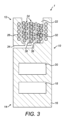
まず、図1~図3を参照すると、エアロゾル生成システム1の第1の実施形態が図示されている。エアロゾル生成システム1は、近位端12及び遠位端14を有するエアロゾル生成装置10を含む。エアロゾル生成装置10は、電源18及び高周波数で動作するように構成され得るコントローラ20を含む装置本体16を含む。電源18は、典型的には、例えば誘導式で充電可能であり得る1つ又は複数の電池を含む。
Referring first to FIGS. 1-3, a first embodiment of an
エアロゾル生成装置10は、概して円筒形であり、エアロゾル生成装置10の近位端12に装置本体16内の空洞として形成される、概して円筒形のエアロゾル生成空間22を含む。エアロゾル生成空間22は、例えば、粉粒体、粒子、ゲル、条片、ばらばらの葉、切断フィラー、ペレット、粉末、断片、線維、発泡材及びシートの形態において、図2及び3に示されるようにエアロゾル生成材料24を受けるように構成される。
エアロゾル生成装置10は、円形断面を有し、且つエアロゾル生成空間22の周りに延びる螺旋形誘導コイル26を含む。誘導コイル26は、電源18及びコントローラ20によって励磁され得る。コントローラ20は、電子部品の中でもとりわけ、電源18からの直流を誘導コイル26のための交流高周波電流に変換するように構成されるインバータを含む。
エアロゾル生成装置10は、近位端12において装置本体16上に着脱可能に取り付けられ、且つ装置10の使用中に生成された蒸気をユーザがそれを通して吸入し得るマウスピース28を含む。図1に図示されているマウスピース28は、装置10の使用中に生成されたエアロゾルがエアロゾル生成空間22からユーザの口内に流れることを可能にする排気口30を含む。
エアロゾル生成システム1は、誘導コイル26によって生成された時変電磁場の存在下で誘導加熱可能な材料から形成される管状サセプタ32を含む。サセプタ32は、使用時にエアロゾル生成空間22において同心円状に配置される。サセプタ32は、例えば、エアロゾル生成装置10の一体コンポーネントとしてエアロゾル生成空間22に永久的に取り付けられ得るか、又は例えば適当なコネクタ(図示せず)によってエアロゾル生成空間22に着脱可能に取り付けられ得る。図1から明らかであるように、サセプタ32は、その長手方向軸が誘導コイル26の長手方向軸と略整列されるようにエアロゾル生成空間22に配置される。エアロゾル生成材料24は、図3に明確に見られ得るように、使用時に管状サセプタの内側及び外側の両方に位置する。
サセプタ32が、エアロゾル生成空間22においてエアロゾル生成装置10に着脱可能に接続可能な別々の要素である場合、サセプタ32は、適当な接続機構によって確実に着脱可能に付着され得る。例えば、装置10は、摩擦嵌合を用いて、又はねじ嵌合(凹部に形成された突合せ溝若しくは隆起と連携するねじ山若しくは溝と共に供給される場合)を用いて、又はバヨネット嵌合を用いて、サセプタ32の端が快適に嵌合され得る連携凹部を含み得る。追加的に又は代替的に、装置10は、エアロゾル生成空間22内の明確な位置にサセプタ32を確実に付着させるための磁石を含み得る。
If the
誘導コイル26によってサセプタ32の近傍において時変電磁場が生じると、渦電流及び/又は磁気ヒステリシス損失に起因してサセプタ32において熱が発生し、この熱は、サセプタ32から、管状サセプタ32の内側及び外側の両方に位置するエアロゾル生成材料24に伝達されて、エアロゾル生成材料24を燃やすことなく加熱し、それにより、ユーザによる吸入のためのエアロゾルを生成する。管状サセプタ32は、実質的にその全体の内側面及び外側面にわたってエアロゾル生成材料24と接触しており、したがってサセプタ32からエアロゾル生成材料24に直接的に且つそれにより効率的に熱を伝達することが可能となる。
When a time-varying electromagnetic field is generated in the vicinity of the
エアロゾル生成装置10は、管状サセプタ32の内部及び管状サセプタ32の外部の両方に空気を向けるように配置される入口ポート36、38を介してエアロゾル生成空間に空気を送出する給気口34を含む。この構成は、エアロゾル生成空間22から排気口30を通してエアロゾルの生成及び送出を最大化すると理解されたい。
上述のように、マウスピース28は、エアロゾル生成空間22へのアクセスを可能にするために装置本体16から好都合に着脱可能である。したがって、マウスピース28は、エアロゾル生成材料24をエアロゾル生成空間22内に挿入可能にするために除去され、その後、エアロゾル生成システム1がエアロゾル生成に使用され得るように装置本体16に再付着され得る。使用期間後、マウスピース28は、使用済みエアロゾル生成材料24が除去されることを可能にするため、及びさらなるエアロゾル生成材料24をエアロゾル生成空間22に配置することを可能にするために再び除去され得る。さらに、マウスピース28を除去することにより、着脱可能に取り付けられたサセプタ32の場合、それが必要に応じて除去及び交換され得るように、サセプタ32へのアクセスも可能となると理解されたい。
As mentioned above, the
着脱可能に取り付けられたサセプタ32を利用するいくつかの実施形態において、コントローラ20は、例えば、サセプタ32に関連する識別特性を検出することにより、又はサセプタ32が新たなサセプタ32と交換されたことを(例えば、所定のボタン押下又は一連の押下などを実行することによって)ユーザが示した結果として、エアロゾル生成空間22内における新たなサセプタ32の取り付けを検出するように構成され得る。新たなサセプタ32の取り付けを検出すると、コントローラ20は、誘導コイル26に供給される電力レベルを検出し、且つ検出された電力レベルに基づいて(サセプタ32を変更する時間であることを示すため若しくは最適に変更されるべきより前のサセプタ32の残り「寿命」を示すためなど)サセプタ32のタイミング変更を示し、且つ/又はコントローラ20が別の新たなサセプタ32がエアロゾル生成空間22に配置されていることを検出するまで、検出された電力レベルに基づいて誘導コイル26への電力供給を中止するようにさらに構成され得る。特に、装置10は、(経時的にコイル26に供給される電力を統合することにより)新たなサセプタ32を挿入してから経時的に誘導コイル26に供給される総エネルギーをモニタリングし得、所定の量のエネルギーがコイル26に供給された後、サセプタ32が変更される時間であると判断し得る。サセプタ32が変更されるべきであるとの通知は、任意の適当な手段を介して、例えば所定のパターンで警告ライトをフラッシュすることなどにより、ユーザに提供され得る。
In some embodiments utilizing a removably attached
いくつかの実施形態では、コントローラ20は、一服の数、合計一服期間の長さ、例えば光センサ(図示せず)を用いた、エアロゾル生成空間22内のエアロゾル生成材料24の配置の数及びエアロゾル生成空間22内のエアロゾル生成材料24の配置を可能にするために必要とされる、エアロゾル生成装置10の1つ又は複数のコンポーネントの移動、例えばマウスピース28の移動の1つ又は複数を検出することにより、エアロゾル生成材料24の消費を検出するように構成され得る。追加的に、サセプタ32が変更されるべきであると判断するための技術は、概して、当業者に明らかであるように、エアロゾル材料24の消費量を検出するためにも使用され、その逆もあることに留意すべきである。
In some embodiments, the
いくつかの実施形態では、コントローラ20は、エアロゾル生成空間22における新たなサセプタ32の配置を検出した後、エアロゾル生成材料24の消費レベルを検出するように有利に構成され得、検出された消費レベルに基づいてサセプタ32のタイミング変更を示し、且つ/又はコントローラ20がエアロゾル生成空間22において別の新たなサセプタ32が配置されていることを検出するまで、検出された消費レベルに基づいて誘導コイル26への電源供給を中止するように構成され得る。
In some embodiments, the
ここで、図4を参照すると、図1~図3に図示されたエアロゾル生成システム1と類似のエアロゾル生成システム2の第2の実施形態が示されており、ここで、対応する要素は、同じ参照番号を使用して示されている。
Referring now to FIG. 4, there is shown a second embodiment of an
エアロゾル生成システム2は、着脱可能なマウスピース28を含まないことを除く全ての点において、上述したエアロゾル生成装置10と同一のエアロゾル生成装置210を含む。
エアロゾル生成システム2において、エアロゾル生成材料24は、マウスピース42に接続されている、例えば包装紙の形態の非導電性ハウジング40において提供される。エアロゾル生成材料24、ハウジング40及びマウスピース42は、エアロゾル生成空間22に着脱可能に配置され得るエアロゾル生成物品44を一緒に構成する。管状サセプタ32は、エアロゾル生成材料24に入り、エアロゾル生成物品44がエアロゾル生成空間22に配置されるときにエアロゾル生成材料24内に完全に延び得、マウスピース42は、ユーザの唇によってふさがれ得るようにエアロゾル生成装置210の遠位端12から突出すると理解されたい。
In the
誘導コイル26によってサセプタ32の近傍において時変電磁場が生じると、熱がサセプタ32において発生し、サセプタ32から、管状サセプタ32の内側及び外側の両方に位置するエアロゾル生成材料24に伝達されて、エアロゾル生成材料24を燃やすことなく加熱し、それにより、ユーザによる吸入のためのエアロゾルを生成するように、エアロゾル生成システム2は、上述したエアロゾル生成システム1と同様に動作する。エアロゾル生成材料24の加熱によって生成されたエアロゾルは、マウスピース42を通してユーザにより吸入される。
When the
使用期間後、エアロゾル生成物品44は、エアロゾル生成空間22から除去され得、さらなるエアロゾル生成物品44は、エアロゾル生成空間22に配置され得る。さらに、エアロゾル生成物品44を除去することにより、着脱可能に取り付けられたサセプタ32の場合、それが必要に応じて除去及び交換され得るように、サセプタ32へのアクセスが可能となると理解されたい。
After a period of use, aerosol-generating
ここで、図5を参照すると、図1~図3に図示されたエアロゾル生成システム1と類似のエアロゾル生成システム3の第3の実施形態が示されており、ここで、対応する要素は、同じ参照番号を使用して示されている。
Referring now to FIG. 5, there is shown a third embodiment of an
エアロゾル生成システム3は、図5に示されるように、サセプタ32がマウスピース28上に取り付けられ、マウスピース28がエアロゾル生成装置310の近位端12において装置本体16上に配置されるときにマウスピース28からエアロゾル生成空間22内に延びることを除く全ての点において、上述したエアロゾル生成装置10と同一のエアロゾル生成装置310を含む。したがって、エアロゾル生成装置310の近位端12においてマウスピース28を装置本体16上に着脱可能に取り付けることにより、サセプタ32がエアロゾル生成空間22に着脱可能に取り付けられる。
The
この構成では、サセプタ32の交換がマウスピース28の交換を必要とするように、サセプタ32は、一体コンポーネントとしてマウスピース28と共に形成され得る。代替的に、サセプタ32が、マウスピース28を交換することなく使用期間後に除去及び交換され得るように、サセプタ32は、例えば、コネクタ(図示せず)により、マウスピース28上に着脱可能に取り付けられ得る。
In this configuration,
ここで、図6を参照すると、図1~図3に図示されたエアロゾル生成システム1と類似のエアロゾル生成システム4の第4の実施形態が示されており、ここで、対応する要素は、同じ参照番号を使用して示されている。
Referring now to FIG. 6, there is shown a fourth embodiment of an aerosol generation system 4 similar to the
エアロゾル生成システム4は、エアロゾル生成装置410の近位端12において一体的に形成されたマウスピース428を有するエアロゾル生成装置410を含み、ここで、エアロゾル生成空間22は、装置410の遠位端14に位置する。エアロゾル生成空間22のカバー46は、遠位端14において装置本体16に着脱可能に取り付け可能である。カバーは、管状サセプタ32の内部及び管状サセプタ32の外部の両方に空気を向けるように配置される給気口ポート48、50を含む。この構成は、エアロゾル生成空間22から空気通路52に沿った且つ排気口30を通したエアロゾルの生成及び送出を最大化すると理解されたい。
Aerosol generation system 4 includes an
エアロゾル生成システム4において、サセプタ32は、図6に示されるように、カバー46上に取り付けられ、カバー46がエアロゾル生成装置410の遠位端14において装置本体16上に配置されるとき、カバー46からエアロゾル生成空間22内に延びる。したがって、サセプタ32は、エアロゾル生成装置410の遠位端14において装置本体16上にカバー46を着脱可能に取り付けることにより、エアロゾル生成空間22に着脱可能に取り付けられる。
In the aerosol generation system 4, the
この構成では、サセプタ32の交換がカバー46の交換を必要とするように、サセプタ32は、一体コンポーネントとしてカバー46と共に形成され得る。代替的に、サセプタ32が、カバー46を交換することなく使用期間後に除去及び交換され得るように、サセプタ32は、例えば、コネクタ(図示せず)により、カバー46上に着脱可能に取り付けられ得る。
In this configuration,
これまでの段落では、例示的な実施形態について説明してきたが、添付の特許請求の範囲から逸脱することなく、これらの実施形態に対する様々な修正形態がなされ得ることが理解されるべきである。したがって、特許請求の広さ及び範囲は、上述した例示的な実施形態に限定されるべきではない。 Although the preceding paragraphs have described exemplary embodiments, it should be understood that various modifications may be made to these embodiments without departing from the scope of the following claims. Therefore, the breadth and scope of the claims should not be limited to the exemplary embodiments described above.
本明細書で特段の断りのない限り又は文脈によって明らかに矛盾しない限り、全ての可能な変形形態における上述した特徴の任意の組み合わせが本開示によって包含される。 Unless stated otherwise herein or clearly contradicted by context, any combination of the above-described features in all possible variations is encompassed by the present disclosure.
文脈が明らかにそうでないことを必要としない限り、本明細書及び特許請求の範囲全体を通して、「含む」、「含んでいる」などの語は、排他的意味又は網羅的意味とは反対に、包含的に、即ち「含むが、限定されない」という意味で解釈されるべきである。 Unless the context clearly requires otherwise, the words "comprising", "comprising" and the like, as opposed to exclusive or exhaustive, are used throughout this specification and claims as opposed to exclusive or exhaustive meanings. It should be interpreted inclusively, ie, in the sense of "including, but not limited to."
Claims (14)
エアロゾル生成装置(10、210、310、410)であって、
エアロゾル生成材料(24)を受けるためのエアロゾル生成空間(22)、
前記エアロゾル生成空間(22)の周りに延びる誘導コイル(26)、及び
コントローラ(20)
を含むエアロゾル生成装置(10、210、310、410)、
時変電磁場の存在下で誘導加熱可能なサセプタ(32)
を含み、
前記サセプタ(32)は、前記エアロゾル生成材料(24)から分離可能であり、且つ前記エアロゾル生成材料(24)から分離された状態で前記エアロゾル生成空間(22)に配置される管状部材を含み、前記エアロゾル生成材料(24)は、使用時に前記エアロゾル生成空間(22)に位置し、使用時に前記管状部材の内側及び外側に位置する、エアロゾル生成システム(1、2、3、4)。 An aerosol generation system (1, 2, 3, 4),
An aerosol generation device (10, 210, 310, 410),
an aerosol generation space (22) for receiving an aerosol generation material (24);
an induction coil (26) extending around the aerosol generation space (22), and a controller (20)
an aerosol generation device (10, 210, 310, 410),
Susceptor capable of induction heating in the presence of a time-varying electromagnetic field (32)
including;
The susceptor (32) includes a tubular member that is separable from the aerosol-generating material (24) and is disposed in the aerosol-generating space (22) while being separated from the aerosol-generating material (24) ; An aerosol generation system (1, 2, 3, 4), wherein said aerosol generation material (24) is located in said aerosol generation space (22) in use and located inside and outside said tubular member in use.
一服の数、
合計一服期間の長さ、
前記エアロゾル生成空間(22)内のエアロゾル生成材料(24)の配置の数、
前記エアロゾル生成空間(22)内のエアロゾル生成材料(24)の配置を可能にするために必要とされる、前記エアロゾル生成装置の1つ又は複数のコンポーネントの移動
の少なくとも1つを検出することにより、エアロゾル生成材料(24)の消費を検出するように構成される、請求項1~6のいずれか一項に記載のエアロゾル生成システム。 The controller (20) includes:
number of puffs,
total duration of cessation period,
the number of arrangements of aerosol-generating materials (24) in the aerosol-generating space (22);
by detecting at least one movement of one or more components of said aerosol generation device required to enable placement of an aerosol generation material (24) within said aerosol generation space (22); Aerosol generation system according to any one of claims 1 to 6, configured to detect consumption of the aerosol generation material (24).
Applications Claiming Priority (3)
| Application Number | Priority Date | Filing Date | Title |
|---|---|---|---|
| EP18173406.2 | 2018-05-21 | ||
| EP18173406 | 2018-05-21 | ||
| PCT/EP2019/062503 WO2019224076A1 (en) | 2018-05-21 | 2019-05-15 | Aerosol generating system |
Publications (2)
| Publication Number | Publication Date |
|---|---|
| JP2021523713A JP2021523713A (en) | 2021-09-09 |
| JP7428662B2 true JP7428662B2 (en) | 2024-02-06 |
Family
ID=62222425
Family Applications (1)
| Application Number | Title | Priority Date | Filing Date |
|---|---|---|---|
| JP2020563897A Active JP7428662B2 (en) | 2018-05-21 | 2019-05-15 | Aerosol generation system |
Country Status (9)
| Country | Link |
|---|---|
| US (1) | US20210106058A1 (en) |
| EP (1) | EP3796796A1 (en) |
| JP (1) | JP7428662B2 (en) |
| KR (1) | KR20210018841A (en) |
| CN (1) | CN112153907A (en) |
| CA (1) | CA3099084A1 (en) |
| EA (2) | EA202092771A1 (en) |
| TW (1) | TW202002819A (en) |
| WO (1) | WO2019224076A1 (en) |
Families Citing this family (1)
| Publication number | Priority date | Publication date | Assignee | Title |
|---|---|---|---|---|
| CA3154806A1 (en) * | 2020-05-19 | 2021-11-25 | Ping Chen | Heating device and manufacturing method therefor, and heat-not-burn smoking device |
Citations (7)
| Publication number | Priority date | Publication date | Assignee | Title |
|---|---|---|---|---|
| US20120227752A1 (en) | 2010-08-24 | 2012-09-13 | Eli Alelov | Inhalation device including substance usage controls |
| CN105852218A (en) | 2016-05-26 | 2016-08-17 | 湖南中烟工业有限责任公司 | Disposable cigarette cartridge and heating non-combustion cigarette utilizing multiple disposable cigarette cartridges |
| WO2017036955A2 (en) | 2015-08-31 | 2017-03-09 | British American Tobacco (Investments) Limited | Apparatus for heating smokable material |
| WO2017036957A1 (en) | 2015-08-31 | 2017-03-09 | British American Tobacco (Investments) Limited | Article for use with apparatus for heating smokable material |
| WO2017068094A1 (en) | 2015-10-22 | 2017-04-27 | Philip Morris Products S.A. | Aerosol-generating article, aerosol-generating system and method for manufacturing an aerosol-generating article |
| CN206137197U (en) | 2016-09-26 | 2017-05-03 | 深圳市合元科技有限公司 | Smog suction means and cigarette prop up |
| WO2018002086A1 (en) | 2016-06-29 | 2018-01-04 | British American Tobacco (Investments) Limited | Apparatus for heating smokable material |
Family Cites Families (12)
| Publication number | Priority date | Publication date | Assignee | Title |
|---|---|---|---|---|
| US5613505A (en) * | 1992-09-11 | 1997-03-25 | Philip Morris Incorporated | Inductive heating systems for smoking articles |
| FR2895644B1 (en) * | 2006-01-03 | 2008-05-16 | Didier Gerard Martzel | SUBSTITUTE OF CIGARETTE |
| US10117460B2 (en) * | 2012-10-08 | 2018-11-06 | Rai Strategic Holdings, Inc. | Electronic smoking article and associated method |
| WO2015082560A1 (en) * | 2013-12-03 | 2015-06-11 | Philip Morris Products S.A. | Aerosol-generating article and electrically operated system incorporating a taggant |
| KR102378679B1 (en) * | 2013-12-19 | 2022-03-28 | 필립모리스 프로덕츠 에스.에이. | Aerosol-generating system for generating and controlling the quantity of nicotine salt particles |
| US11696604B2 (en) * | 2014-03-13 | 2023-07-11 | Rai Strategic Holdings, Inc. | Aerosol delivery device and related method and computer program product for controlling an aerosol delivery device based on input characteristics |
| TWI660685B (en) * | 2014-05-21 | 2019-06-01 | 瑞士商菲利浦莫里斯製品股份有限公司 | Electrically heated aerosol-generating system and cartridge for use in such a system |
| TWI669072B (en) * | 2014-05-21 | 2019-08-21 | 瑞士商菲利浦莫里斯製品股份有限公司 | Electrically heated aerosol-generating system and cartridge for use in such a system |
| CN106028848B (en) * | 2014-12-26 | 2019-10-29 | 惠州市吉瑞科技有限公司 | A kind of electronic cigarette control method and electronic cigarette |
| US10226073B2 (en) * | 2015-06-09 | 2019-03-12 | Rai Strategic Holdings, Inc. | Electronic smoking article including a heating apparatus implementing a solid aerosol generating source, and associated apparatus and method |
| GB201511358D0 (en) * | 2015-06-29 | 2015-08-12 | Nicoventures Holdings Ltd | Electronic aerosol provision systems |
| GB201511349D0 (en) * | 2015-06-29 | 2015-08-12 | Nicoventures Holdings Ltd | Electronic aerosol provision systems |
-
2018
- 2018-06-08 EA EA202092771A patent/EA202092771A1/en unknown
-
2019
- 2019-05-15 EA EA202092770A patent/EA202092770A1/en unknown
- 2019-05-15 KR KR1020207036210A patent/KR20210018841A/en not_active Application Discontinuation
- 2019-05-15 US US17/046,625 patent/US20210106058A1/en active Pending
- 2019-05-15 JP JP2020563897A patent/JP7428662B2/en active Active
- 2019-05-15 WO PCT/EP2019/062503 patent/WO2019224076A1/en unknown
- 2019-05-15 EP EP19725323.0A patent/EP3796796A1/en active Pending
- 2019-05-15 CA CA3099084A patent/CA3099084A1/en active Pending
- 2019-05-15 CN CN201980033484.0A patent/CN112153907A/en active Pending
- 2019-05-20 TW TW108117281A patent/TW202002819A/en unknown
Patent Citations (7)
| Publication number | Priority date | Publication date | Assignee | Title |
|---|---|---|---|---|
| US20120227752A1 (en) | 2010-08-24 | 2012-09-13 | Eli Alelov | Inhalation device including substance usage controls |
| WO2017036955A2 (en) | 2015-08-31 | 2017-03-09 | British American Tobacco (Investments) Limited | Apparatus for heating smokable material |
| WO2017036957A1 (en) | 2015-08-31 | 2017-03-09 | British American Tobacco (Investments) Limited | Article for use with apparatus for heating smokable material |
| WO2017068094A1 (en) | 2015-10-22 | 2017-04-27 | Philip Morris Products S.A. | Aerosol-generating article, aerosol-generating system and method for manufacturing an aerosol-generating article |
| CN105852218A (en) | 2016-05-26 | 2016-08-17 | 湖南中烟工业有限责任公司 | Disposable cigarette cartridge and heating non-combustion cigarette utilizing multiple disposable cigarette cartridges |
| WO2018002086A1 (en) | 2016-06-29 | 2018-01-04 | British American Tobacco (Investments) Limited | Apparatus for heating smokable material |
| CN206137197U (en) | 2016-09-26 | 2017-05-03 | 深圳市合元科技有限公司 | Smog suction means and cigarette prop up |
Also Published As
| Publication number | Publication date |
|---|---|
| US20210106058A1 (en) | 2021-04-15 |
| EP3796796A1 (en) | 2021-03-31 |
| CA3099084A1 (en) | 2019-11-28 |
| EA202092771A1 (en) | 2021-03-15 |
| WO2019224076A1 (en) | 2019-11-28 |
| TW202002819A (en) | 2020-01-16 |
| CN112153907A (en) | 2020-12-29 |
| KR20210018841A (en) | 2021-02-18 |
| EA202092770A1 (en) | 2021-03-15 |
| JP2021523713A (en) | 2021-09-09 |
Similar Documents
| Publication | Publication Date | Title |
|---|---|---|
| US20190380391A1 (en) | Inductively heated aerosol-generating device comprising a reusable susceptor | |
| JP7332632B2 (en) | aerosol generating device | |
| TW202400033A (en) | An aerosol generating article, a method for manufacturing an aerosol generating article and an aerosol generating system | |
| JP7428662B2 (en) | Aerosol generation system | |
| TW202123829A (en) | An aerosol generating article and an aerosol generating system | |
| TW202123830A (en) | An aerosol generating article and an aerosol generating system | |
| EA041372B1 (en) | AEROSOL GENERATING SYSTEM | |
| JP7471822B2 (en) | Heating components in aerosol generating devices | |
| KR20230142531A (en) | Induction heating assembly for aerosol generating device | |
| RU2793731C2 (en) | Induction heating unit for induction heating of aerosol forming substrate | |
| RU2792842C2 (en) | Susceptor node for induction heating of aerosol forming substrate | |
| CN112739227B (en) | Inductively heatable aerosol-generating article comprising an aerosol-forming substrate and a susceptor assembly | |
| JP2024504561A (en) | Induction heating assembly for aerosol generation devices | |
| JP2024504562A (en) | Aerosol generation device and aerosol generation system | |
| KR20230141811A (en) | Aerosol generating device and aerosol generating system | |
| KR20230142513A (en) | Aerosol generating device and aerosol generating system | |
| WO2022268790A1 (en) | An aerosol generating article comprising a susceptor | |
| EA041927B1 (en) | AEROSOL GENERATING DEVICE | |
| JP2020521439A (en) | Heating components in an aerosol generator |
Legal Events
| Date | Code | Title | Description |
|---|---|---|---|
| A621 | Written request for application examination |
Free format text: JAPANESE INTERMEDIATE CODE: A621 Effective date: 20220222 |
|
| A131 | Notification of reasons for refusal |
Free format text: JAPANESE INTERMEDIATE CODE: A131 Effective date: 20230227 |
|
| A521 | Request for written amendment filed |
Free format text: JAPANESE INTERMEDIATE CODE: A523 Effective date: 20230403 |
|
| A131 | Notification of reasons for refusal |
Free format text: JAPANESE INTERMEDIATE CODE: A131 Effective date: 20230712 |
|
| A131 | Notification of reasons for refusal |
Free format text: JAPANESE INTERMEDIATE CODE: A131 Effective date: 20231201 |
|
| A521 | Request for written amendment filed |
Free format text: JAPANESE INTERMEDIATE CODE: A523 Effective date: 20231221 |
|
| TRDD | Decision of grant or rejection written | ||
| A01 | Written decision to grant a patent or to grant a registration (utility model) |
Free format text: JAPANESE INTERMEDIATE CODE: A01 Effective date: 20231227 |
|
| A61 | First payment of annual fees (during grant procedure) |
Free format text: JAPANESE INTERMEDIATE CODE: A61 Effective date: 20240125 |
|
| R150 | Certificate of patent or registration of utility model |
Ref document number: 7428662 Country of ref document: JP Free format text: JAPANESE INTERMEDIATE CODE: R150 |