EP4237763B1 - Wärmepumpe - Google Patents
Wärmepumpe Download PDFInfo
- Publication number
- EP4237763B1 EP4237763B1 EP21814677.7A EP21814677A EP4237763B1 EP 4237763 B1 EP4237763 B1 EP 4237763B1 EP 21814677 A EP21814677 A EP 21814677A EP 4237763 B1 EP4237763 B1 EP 4237763B1
- Authority
- EP
- European Patent Office
- Prior art keywords
- refrigerant
- collector
- heat pump
- pump according
- condensate
- Prior art date
- Legal status (The legal status is an assumption and is not a legal conclusion. Google has not performed a legal analysis and makes no representation as to the accuracy of the status listed.)
- Active
Links
Images
Classifications
-
- F—MECHANICAL ENGINEERING; LIGHTING; HEATING; WEAPONS; BLASTING
- F25—REFRIGERATION OR COOLING; COMBINED HEATING AND REFRIGERATION SYSTEMS; HEAT PUMP SYSTEMS; MANUFACTURE OR STORAGE OF ICE; LIQUEFACTION SOLIDIFICATION OF GASES
- F25B—REFRIGERATION MACHINES, PLANTS OR SYSTEMS; COMBINED HEATING AND REFRIGERATION SYSTEMS; HEAT PUMP SYSTEMS
- F25B47/00—Arrangements for preventing or removing deposits or corrosion, not provided for in another subclass
-
- F—MECHANICAL ENGINEERING; LIGHTING; HEATING; WEAPONS; BLASTING
- F25—REFRIGERATION OR COOLING; COMBINED HEATING AND REFRIGERATION SYSTEMS; HEAT PUMP SYSTEMS; MANUFACTURE OR STORAGE OF ICE; LIQUEFACTION SOLIDIFICATION OF GASES
- F25B—REFRIGERATION MACHINES, PLANTS OR SYSTEMS; COMBINED HEATING AND REFRIGERATION SYSTEMS; HEAT PUMP SYSTEMS
- F25B13/00—Compression machines, plants or systems, with reversible cycle
-
- F—MECHANICAL ENGINEERING; LIGHTING; HEATING; WEAPONS; BLASTING
- F25—REFRIGERATION OR COOLING; COMBINED HEATING AND REFRIGERATION SYSTEMS; HEAT PUMP SYSTEMS; MANUFACTURE OR STORAGE OF ICE; LIQUEFACTION SOLIDIFICATION OF GASES
- F25D—REFRIGERATORS; COLD ROOMS; ICE-BOXES; COOLING OR FREEZING APPARATUS NOT OTHERWISE PROVIDED FOR
- F25D21/00—Defrosting; Preventing frosting; Removing condensed or defrost water
- F25D21/14—Collecting or removing condensed and defrost water; Drip trays
-
- F—MECHANICAL ENGINEERING; LIGHTING; HEATING; WEAPONS; BLASTING
- F25—REFRIGERATION OR COOLING; COMBINED HEATING AND REFRIGERATION SYSTEMS; HEAT PUMP SYSTEMS; MANUFACTURE OR STORAGE OF ICE; LIQUEFACTION SOLIDIFICATION OF GASES
- F25B—REFRIGERATION MACHINES, PLANTS OR SYSTEMS; COMBINED HEATING AND REFRIGERATION SYSTEMS; HEAT PUMP SYSTEMS
- F25B2400/00—General features or devices for refrigeration machines, plants or systems, combined heating and refrigeration systems or heat-pump systems, i.e. not limited to a particular subgroup of F25B
- F25B2400/16—Receivers
-
- F—MECHANICAL ENGINEERING; LIGHTING; HEATING; WEAPONS; BLASTING
- F25—REFRIGERATION OR COOLING; COMBINED HEATING AND REFRIGERATION SYSTEMS; HEAT PUMP SYSTEMS; MANUFACTURE OR STORAGE OF ICE; LIQUEFACTION SOLIDIFICATION OF GASES
- F25D—REFRIGERATORS; COLD ROOMS; ICE-BOXES; COOLING OR FREEZING APPARATUS NOT OTHERWISE PROVIDED FOR
- F25D2321/00—Details or arrangements for defrosting; Preventing frosting; Removing condensed or defrost water, not provided for in other groups of this subclass
- F25D2321/14—Collecting condense or defrost water; Removing condense or defrost water
Definitions
- the invention relates to a heat pump according to the preamble of patent claim 1.
- Another heat pump of a similar type is known from the patent document EP 2 500 676 B1
- This consists of a refrigerant circuit for a refrigerant, a refrigerant collector belonging to the refrigerant circuit through which the refrigerant flows, an expansion device belonging to the refrigerant circuit through which the refrigerant flows and downstream of the refrigerant collector in the direction of flow of the refrigerant, an evaporator belonging to the refrigerant circuit through which the refrigerant flows and downstream of the expansion device in the direction of flow of the refrigerant, and a condensate tray associated with the evaporator for collecting condensate that accumulates on the evaporator.
- a heat exchanger is arranged in the condensate tray to keep it free of ice. The refrigerant flows through this and is then fed to the evaporator itself.
- the invention is based on the object of improving a heat pump of the type mentioned at the beginning.
- the efficiency of the heat pump is to be increased.
- the solution according to the invention is characterized in that heat accumulating in particular on an outer wall of the coolant collector is transferred to the condensate pan by heat conduction.
- heat transfer takes place in the broadest sense, in particular optionally to a foreseeable only very small extent, via the aforementioned pipe ( EP 3 358 277 A1 ) or by convection (EP 2 500 676 B1 ), namely by constantly conveying new warm refrigerant to the condensate pan via a pipe and the heat exchanger mentioned, i.e. the heat is transferred to the condensate pan using the refrigerant.
- the heat that is already present on the outside of the refrigerant collector is transferred to the condensate pan in particular by heat conduction (and possibly also by heat radiation), which accordingly increases the efficiency of the heat pump.
- the requirement that the refrigerant collector is connected to the condensate pan in a heat-conducting manner includes, on the one hand, the option that this (i.e. the refrigerant collector) is arranged directly on the condensate pan, i.e. in direct contact with it, but on the other hand it can also be provided that between the refrigerant collector and the condensate pan a heat conducting body is arranged which conducts the heat from the refrigerant collector to the condensate tray.
- the present, in the Figures 1 and 2 The invention shown relates to a heat pump.
- This consists of a refrigerant circuit 1 for a refrigerant, a refrigerant collector 2 belonging to the refrigerant circuit 1 and through which the refrigerant flows, an expansion device 3 belonging to the refrigerant circuit 1 and through which the refrigerant flows and downstream of the refrigerant collector 2 as seen in the flow direction of the refrigerant, an evaporator belonging to the refrigerant circuit 1 and through which the refrigerant flows and downstream of the expansion device 3 as seen in the flow direction of the refrigerant 4 and a condensate tray 5 assigned to the evaporator 4 for collecting condensate accumulating at the evaporator 4.
- the coolant collector 2 is connected to the condensate pan 5 in a heat-conducting manner.
- the coolant collector 2 is connected to the condensate pan 5 in a "convection-free" manner.
- the heat-conducting element 6 is designed to be contact-free with the coolant. This means, for example, that a pipe carrying the coolant does not serve as the heat-conducting element 6, but rather a separate heat-conducting element 6 is provided for heat conduction.
- an electrical heating device that may be provided on the condensate tray to keep it free of ice can be dispensed with, which ultimately increases the efficiency of the heat pump.
- a distance between the coolant collector 2 and the condensate tray 5 is a maximum of 15 cm, preferably less than 10 cm, particularly preferably less than 5 cm, or even (only) 0 cm.
- the latter case is in Figure 1 shown, ie in this solution it is provided that the refrigerant collector 2 and the condensate pan 5 are designed to touch each other.
- a preferably (because it is a good heat conductor) metallic heat conducting element 6 is arranged between the refrigerant collector 2 and the condensate pan 5, see Figure 2
- the inventive requirement of "maximum 15 cm” is based on the pragmatic consideration that with a significantly larger distance (such as the aforementioned EP 3 358 277 A1 ) heat transfer relevant to the intended purpose can no longer be achieved.
- the coolant collector 2 is preferably arranged below the condensate tray 5. It is also preferred that the condensate tray 5 has a drainage channel and/or that the coolant collector 2 is connected in a heat-conducting manner at least to the drainage channel.
- the refrigerant collector 2 is designed as a high-pressure collector.
- the refrigerant circuit 1 preferably has a high-pressure side 1.1 with the condenser 8 and a low-pressure side 1.2 with the evaporator 4. It is also preferred that the refrigerant collector 2 is arranged on the high-pressure side 1.1 of the refrigerant circuit 1. This means that the refrigerant in the refrigerant collector 2 and thus the refrigerant collector 2 itself has a relatively high temperature. A lot of heat energy can thus be transferred to the condensate pan 5 in order to thaw it.
- the refrigerant circuit 1 has a compressor 7 through which the refrigerant flows and which is connected downstream of the evaporator 4 as seen in the flow direction of the refrigerant.
- the refrigerant circuit 1 has a condenser 8 through which the refrigerant flows and which is connected downstream of the compressor 7 as seen in the flow direction of the refrigerant.
- the heat pump according to the invention according to the embodiment of Figure 1 works as follows ( Figure 2 corresponding analogously): During normal operation of the heat pump, condensate forms on the relatively cool evaporator 4, which drips down from it and is collected in the condensate tray 5. Since the condensate itself is cold, it can happen that the condensate tray 5 freezes and the condensate can no longer escape properly through a drain from the condensate tray 5.
- the refrigerant collector 2 is now located directly under the condensate tray 5. This refrigerant collector 2 contains warm refrigerant, which heats up the refrigerant collector 2.
- the refrigerant collector 2 Since the refrigerant collector 2 is in direct contact with the condensate tray 5 (or according to Figure 2 connected to it via the heat conducting element 6), it passes on part of its heat energy to it, whereby the ice in it is thawed or melted, or cannot even form during operation of the heat pump.
- the heat pump according to the invention thus prevents the condensate tray 5 from freezing in a simple and efficient manner, which in turn improves the efficiency of the heat pump itself.
Landscapes
- Engineering & Computer Science (AREA)
- Physics & Mathematics (AREA)
- Mechanical Engineering (AREA)
- Thermal Sciences (AREA)
- General Engineering & Computer Science (AREA)
- Chemical & Material Sciences (AREA)
- Combustion & Propulsion (AREA)
- Other Air-Conditioning Systems (AREA)
- Central Heating Systems (AREA)
- Heat-Pump Type And Storage Water Heaters (AREA)
- Compression-Type Refrigeration Machines With Reversible Cycles (AREA)
Description
- Die Erfindung betrifft eine Wärmepumpe gemäß dem Oberbegriff des Patentanspruchs 1.
- Eine Wärmepumpe der eingangs genannten Art ist aus dem Patentdokument
EP 3 358 277 A1 bekannt. Im weitest möglichen Sinne betrachtet ist bei dieser Lösung ein dort vorgesehener Kältemittelsammler mittels eines Rohres wärmeleitend mit einer dort vorgesehenen Kondensatwanne verbunden ausgebildet. - Eine weitere Wärmepumpe ähnlicher Art ist aus dem Patentdokument
EP 2 500 676 B1 bekannt. Diese besteht aus einem Kältemittelkreislauf für ein Kältemittel, einem zum Kältekreislauf gehörenden, vom Kältemittel durchströmten Kältemittelsammler, einer zum Kältekreislauf gehörenden, vom Kältemittel durchströmten und in Strömungsrichtung des Kältemittels gesehen dem Kältemittelsammler nachgeschalteten Expansionseinrichtung, einem zum Kältekreislauf gehörenden, vom Kältemittel durchströmten und in Strömungsrichtung des Kältemittels gesehen der Expansionseinrichtung nachgeschalteten Verdampfer und einer dem Verdampfer zugeordnete Kondensatwanne zum Auffangen von am Verdampfer anfallendem Kondensat. Bei dieser Lösung ist in der Kondensatwanne, um diese eisfrei zu halten, ein Wärmeübertrager angeordnet. Dieser wird von Kältemittel durchströmt, das anschließend dem Verdampfer selbst zugeführt wird. - Der Erfindung liegt die Aufgabe zugrunde, eine Wärmepumpe der eingangs genannten Art zu verbessern. Insbesondere soll die Effizienz der Wärmepumpe gesteigert werden.
- Diese Aufgabe ist mit einer Wärmepumpe der eingangs genannten Art durch die im Kennzeichen des Patentanspruchs 1 aufgeführten Merkmale gelöst.
- Nach der Erfindung ist also vorgesehen, dass zur Übertragung durch Wärmeleitung von außen am Kältemittelsammler vorliegender Wärme auf die Kondensatwanne ein Abstand zwischen dem Kältemittelsammler und der Kondensatwanne maximal 15 cm beträgt.
- Mit anderen Worten zeichnet sich die erfindungsgemäße Lösung somit dadurch aus, dass insbesondere an einer Außenwandung des Kältemittelsammlers anfallende Wärme per Wärmeleitung auf die Kondensatwanne übertragen wird. Beim vorgenannten Stand der Technik erfolgt die Wärmeübertragung dagegen im weitesten Sinne insbesondere wahlweise in absehbar nur sehr geringem Maße über die genannte Rohrleitung (
EP 3 358 277 A1 ) oder durch Konvektion (EP 2 500 676 B1 ), nämlich dadurch, dass stets neues warmes Kältemittel über eine Leitung und den besagten Wärmeübertrager zur Kondensatwanne gefördert wird, d. h. die Wärme wird extra mittels des Kältemittels zur Kondensatwanne verbracht. Bei der erfindungsgemäßen Lösung wird dagegen, wie bereits erläutert, die außen am Kältemittelsammler ohnehin vorliegende Wärme insbesondere durch Wärmeleitung (und gegebenenfalls auch durch Wärmestrahlung) auf die Kondensatwanne übertragen, was entsprechend die Effizienz der Wärmepumpe steigert. Die Maßgabe, dass der Kältemittelsammler wärmeleitend mit der Kondensatwanne verbunden ausgebildet ist, umfasst dabei einerseits die Option, dass dieser (also der Kältemittelsammler) direkt an der Kondensatwanne, also diese direkt berührend, angeordnet ist, andererseits kann aber auch vorgesehen sein, dass zwischen dem Kältemittelsammler und der Kondensatwanne eine Wärmeleitkörper angeordnet ist, der die Wärme vom Kältemittelsammler zur Kondensatwanne leitet. - Andere vorteilhafte Weiterbildungen der erfindungsgemäßen Wärmepumpe ergeben sich aus den abhängigen Patentansprüchen.
- Die erfindungsgemäße Wärmepumpe einschließlich ihrer vorteilhaften Weiterbildungen gemäß der abhängigen Patentansprüche wird nachfolgend anhand der zeichnerischen Darstellung zweier Ausführungsbeispiele näher erläutert.
- Es zeigt
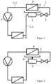
- Figur 1
- schematisch eine erste Ausführungsform der erfindungsgemäßen Wärmepumpe, bei der der Kältemittelsammler und die Kondensatwanne direkt miteinander verbunden ausgebildet sind; und
- Figur 2
- schematisch eine zweite Ausführungsform der erfindungsgemäßen Wärmepumpe, bei der der Kältemittelsammler und die Kondensatwanne über ein Wärmeleitelement miteinander verbunden ausgebildet sind.
- Die vorliegende, in den
Figuren 1 und 2 dargestellte Erfindung betrifft eine Wärmepumpe. Diese besteht aus einem Kältemittelkreislauf 1 für ein Kältemittel, einem zum Kältekreislauf 1 gehörenden, vom Kältemittel durchströmten Kältemittelsammler 2, einer zum Kältekreislauf 1 gehörenden, vom Kältemittel durchströmten und in Strömungsrichtung des Kältemittels gesehen dem Kältemittelsammler 2 nachgeschalteten Expansionseinrichtung 3, einem zum Kältekreislauf 1 gehörenden, vom Kältemittel durchströmten und in Strömungsrichtung des Kältemittels gesehen der Expansionseinrichtung 3 nachgeschalteten Verdampfer 4 und einer dem Verdampfer 4 zugeordneten Kondensatwanne 5 zum Auffangen von am Verdampfer 4 anfallendem Kondensat. - Weiterhin ist vorgesehen, dass der Kältemittelsammler 2 wärmeleitend mit der Kondensatwanne 5 verbunden ausgebildet ist. Insbesondere ist bevorzugt vorgesehen, dass Kältemittelsammler 2 "konvektionsfrei" mit der Kondensatwanne 5 verbunden ausgebildet ist. Dabei ist weiterhin bevorzugt, dass das Wärmeleitelement 6 kontaktfrei zum Kältemittel ausgebildet ist. Dies bedeutet, dass zum Beispiel insbesondere nicht eine das Kältemittel führende Rohrleitung als Wärmeleitelement 6 dient, sondern ein zur Wärmeleitung separates Wärmeleitelement 6 vorgesehen ist.
- Auf eine möglicherweise an der Kondensatwanne zum Eisfreihalten vorgesehene elektrische Heizeinrichtung kann, wie ersichtlich, Dank der erfindungsgemäßen Lösung verzichtet werden, wodurch letztlich die Effizienz der Wärmepumpe gesteigert wird.
- Wesentlich für die erfindungsgemäße Wärmepumpe ist nun, dass ein Abstand zwischen dem Kältemittelsammler 2 und der Kondensatwanne 5 maximal 15 cm, vorzugsweise weniger als 10 cm, besonders bevorzugt weniger als 5 cm, oder sogar (nur) 0 cm beträgt. Letzterer Fall ist in
Figur 1 dargestellt, d. h. bei dieser Lösung ist vorgesehen, dass sich der Kältemittelsammler 2 und die Kondensatwanne 5 berührend ausgebildet sind. Alternativ ist bevorzugt, dass zwischen dem Kältemittelsammler 2 und der Kondensatwanne 5 ein vorzugsweise (weil gut wärmeleitend) metallisches Wärmeleitelement 6 angeordnet ist, sieheFigur 2 . Die erfindungsgemäße Maßgabe bezüglich der "maximal 15 cm" orientiert sich dabei an der pragmatischen Überlegung, dass mit einem deutlich größeren Abstand (wie zum Beispiel bei der eingangs genanntenEP 3 358 277 A1 ) keine für den vorgesehenen Zweck relevante Wärmeübertragung mehr erreichbar ist. - Weiterhin ist der Kältemittelsammler 2 bei bestimmungsgemäßem Betrieb der Wärmepumpe vorzugsweise unterhalb der Kondensatwanne 5 angeordnet. Ebenso ist bevorzugt, dass die Kondensatwanne 5 eine Ablaufrinne aufweist und/oder dass der Kältemittelsammler 2 wenigstens mit der Ablaufrinne wärmeleitend verbunden ausgebildet ist.
- Zudem ist bevorzugt, dass der Kältemittelsammler 2 als Hochdrucksammler ausgebildet ist. Dabei weist der Kältemittelkreislauf 1 vorzugsweise eine Hochdruckseite 1.1 mit dem Kondensator 8 und eine Niederdruckseite 1.2 mit dem Verdampfer 4 auf. Des Weiteren ist bevorzugt, dass der Kältemittelsammler 2 auf der Hochdruckseite 1.1 des Kältemittelkreislaufs 1 angeordnet ist. Dies bewirkt, dass das Kältemittel im Kältemittelsammler 2 und damit der Kältemittelsammler 2 selbst eine relativ hohe Temperatur aufweist. Somit kann viel Wärmeenergie auf die Kondensatwanne 5 übertragen werden, um diese aufzutauen.
- Des Weiteren ist bevorzugt, dass der Kältemittelkreislauf 1 einen vom Kältemittel durchströmten, in Strömungsrichtung des Kältemittels gesehen dem Verdampfer 4 nachgeschalteten Verdichter 7 aufweist. Schließlich ist bevorzugt, dass der Kältemittelkreislauf 1 einen vom Kältemittel durchströmten, in Strömungsrichtung des Kältemittels gesehen dem Verdichter 7 nachgeschalteten Kondensator 8 aufweist.
- Die erfindungsgemäße Wärmepumpe gemäß dem Ausführungsbeispiel aus
Figur 1 funktioniert wie folgt (Figur 2 entsprechend analog) :
Im regulären Betrieb der Wärmepumpe bildet sich am relativ kühlen Verdampfer 4 ein Kondensat, welches von diesem herunter tropft und von der Kondensatwanne 5 aufgefangen wird. Da das Kondensat selbst kalt ist, kann es vorkommen, dass die Kondensatwanne 5 vereist und das Kondensat nicht mehr ordnungsgemäß durch einen Abfluss aus der Kondensatwanne 5 entweichen kann. Bei der erfindungsgemäßen Wärmepumpe gemäß dem Ausführungsbeispiel ausFigur 1 ist nun direkt unter der Kondensatwanne 5 der Kältemittelsammler 2 angeordnet. In diesem Kältemittelsammler 2 befindet sich warmes Kältemittel, welches den Kältemittelsammler 2 aufheizt. Da der Kältemittelsammler 2 unmittelbar mit der Kondensatwanne 5 in Kontakt steht (bzw. gemäßFigur 2 mit diesem über das Wärmeleitelement 6 verbunden ist), gibt er einen Teil seiner Wärmeenergie an diese weiter, wodurch das in ihr befindliche Eis ab- oder aufgetaut wird, bzw. im laufenden Betrieb der Wärmepumpe erst gar nicht entstehen kann. Die erfindungsgemäße Wärmepumpe verhindert also auf einfache und effiziente Art das Einfrieren der Kondensatwanne 5, was wiederum die Effizienz der Wärmepumpe selbst verbessert. -
- 1
- Kältekreislauf
- 1.1
- Hochdruckseite
- 1.2
- Niederdruckseite
- 2
- Kältemittelsammler
- 3
- Expansionseinrichtung
- 4
- Verdampfer
- 5
- Kondensatwanne
- 6
- Wärmeleitelement
- 7
- Verdichter
- 8
- Kondensator
Claims (10)
- Wärmepumpe, umfassend einen Kältemittelkreislauf (1) für ein Kältemittel, einen zum Kältekreislauf (1) gehörenden, vom Kältemittel durchströmten Kältemittelsammler (2), eine zum Kältekreislauf (1) gehörende, vom Kältemittel durchströmte und in Strömungsrichtung des Kältemittels gesehen dem Kältemittelsammler (2) nachgeschaltete Expansionseinrichtung (3), einen zum Kältekreislauf (1) gehörenden, vom Kältemittel durchströmten und in Strömungsrichtung des Kältemittels gesehen der Expansionseinrichtung (3) nachgeschalteten Verdampfer (4) und eine dem Verdampfer (4) zugeordnete Kondensatwanne (5) zum Auffangen von am Verdampfer (4) anfallendem Kondensat, wobei der Kältemittelsammler (2) wärmeleitend mit der Kondensatwanne (5) verbunden ausgebildet ist,
dadurch gekennzeichnet,
dass zur Übertragung durch Wärmeleitung von außen am Kältemittelsammler (2) vorliegender Wärme auf die Kondensatwanne ein Abstand zwischen dem Kältemittelsammler (2) und der Kondensatwanne (5) maximal 15 cm beträgt. - Wärmepumpe nach Anspruch 1,
dadurch gekennzeichnet,
dass ein Abstand zwischen dem Kältemittelsammler (2) und der Kondensatwanne (5) weniger als 10 cm, besonders bevorzugt weniger als 5 cm, oder 0 cm beträgt. - Wärmepumpe nach Anspruch 1 oder der ersten Alternative von Anspruch 2,
dadurch gekennzeichnet,
dass zwischen dem Kältemittelsammler (2) und der Kondensatwanne (5) ein Wärmeleitelement (6) angeordnet ist. - Wärmepumpe nach Anspruch 3,
dadurch gekennzeichnet,
dass das Wärmeleitelement (6) kontaktfrei zum Kältemittel ausgebildet ist. - Wärmepumpe nach einem der Ansprüche 1 bis 4,
dadurch gekennzeichnet,
dass der Kältemittelsammler (2) bei bestimmungsgemäßem Betrieb der Wärmepumpe unterhalb der Kondensatwanne (5) angeordnet ist. - Wärmepumpe nach einem der Ansprüche 1 bis 5, wobei die Kondensatwanne (5) eine Ablaufrinne aufweist,
dadurch gekennzeichnet,
dass der Kältemittelsammler (2) wenigstens mit der Ablaufrinne wärmeleitend verbunden ausgebildet ist. - Wärmepumpe nach einem der Ansprüche 1 bis 6,
dadurch gekennzeichnet,
dass der Kältemittelsammler (2) als Hochdrucksammler ausgebildet ist. - Wärmepumpe nach einem der Ansprüche 1 bis 7, wobei der Kältemittelkreislauf (1) eine Hochdruckseite (1.1) und eine Niederdruckseite (1.2) aufweist,
dadurch gekennzeichnet,
dass der Kältemittelsammler (2) auf der Hochdruckseite (1.1) des Kältemittelkreislaufs (1) angeordnet ist. - Wärmepumpe nach einem der Ansprüche 1 bis 8,
dadurch gekennzeichnet,
dass der Kältemittelkreislauf (1) einen vom Kältemittel durchströmten, in Strömungsrichtung des Kältemittels gesehen dem Verdampfer (4) nachgeschalteten Verdichter (7) aufweist. - Wärmepumpe nach Anspruch 9,
dadurch gekennzeichnet,
dass der Kältemittelkreislauf (1) einen vom Kältemittel durchströmten, in Strömungsrichtung des Kältemittels gesehen dem Verdichter (7) nachgeschalteten Kondensator (8) aufweist.
Applications Claiming Priority (2)
| Application Number | Priority Date | Filing Date | Title |
|---|---|---|---|
| DE102020128276.1A DE102020128276A1 (de) | 2020-10-28 | 2020-10-28 | Wärmepumpe |
| PCT/DE2021/100856 WO2022089687A1 (de) | 2020-10-28 | 2021-10-26 | Wärmepumpe |
Publications (3)
| Publication Number | Publication Date |
|---|---|
| EP4237763A1 EP4237763A1 (de) | 2023-09-06 |
| EP4237763C0 EP4237763C0 (de) | 2024-10-16 |
| EP4237763B1 true EP4237763B1 (de) | 2024-10-16 |
Family
ID=78770304
Family Applications (1)
| Application Number | Title | Priority Date | Filing Date |
|---|---|---|---|
| EP21814677.7A Active EP4237763B1 (de) | 2020-10-28 | 2021-10-26 | Wärmepumpe |
Country Status (5)
| Country | Link |
|---|---|
| US (1) | US20230384019A1 (de) |
| EP (1) | EP4237763B1 (de) |
| CN (1) | CN116368338B (de) |
| DE (1) | DE102020128276A1 (de) |
| WO (1) | WO2022089687A1 (de) |
Family Cites Families (10)
| Publication number | Priority date | Publication date | Assignee | Title |
|---|---|---|---|---|
| US3451226A (en) * | 1967-11-29 | 1969-06-24 | Frick Co | Drip pan having defrosting means |
| JPH08303912A (ja) * | 1995-05-11 | 1996-11-22 | Mitsubishi Heavy Ind Ltd | 冷凍装置 |
| DE102004012498A1 (de) * | 2004-03-15 | 2005-10-06 | BSH Bosch und Siemens Hausgeräte GmbH | Kältegerät |
| JP5528903B2 (ja) * | 2010-05-12 | 2014-06-25 | 矢崎エナジーシステム株式会社 | 吸収式冷暖房給湯システム |
| US20120055185A1 (en) * | 2010-09-02 | 2012-03-08 | Ran Luo | Refrigeration apparatus |
| EP2500676B1 (de) | 2011-03-14 | 2019-07-03 | STIEBEL ELTRON GmbH & Co. KG | Wärmepumpe |
| JP2013019641A (ja) * | 2011-07-13 | 2013-01-31 | Toshiba Corp | 冷蔵庫 |
| DE202013101884U1 (de) * | 2013-04-30 | 2013-05-17 | Carcoustics Techconsult Gmbh | Vorrichtung zum Aufnehmen und Verdampfen von kondensierten Flüssigkeiten an einer Kälteanlage und Kälteanlage mit dieser Vorrichtung |
| JP6191671B2 (ja) | 2015-09-30 | 2017-09-06 | ダイキン工業株式会社 | 冷媒漏洩箇所特定方法 |
| WO2017165924A1 (en) * | 2016-04-01 | 2017-10-05 | Hvps Holdings (Pty) Limited | An air conditioning system |
-
2020
- 2020-10-28 DE DE102020128276.1A patent/DE102020128276A1/de active Pending
-
2021
- 2021-10-26 CN CN202180074211.8A patent/CN116368338B/zh active Active
- 2021-10-26 EP EP21814677.7A patent/EP4237763B1/de active Active
- 2021-10-26 US US18/031,658 patent/US20230384019A1/en active Pending
- 2021-10-26 WO PCT/DE2021/100856 patent/WO2022089687A1/de not_active Ceased
Also Published As
| Publication number | Publication date |
|---|---|
| CN116368338A (zh) | 2023-06-30 |
| WO2022089687A1 (de) | 2022-05-05 |
| EP4237763A1 (de) | 2023-09-06 |
| CN116368338B (zh) | 2025-11-07 |
| DE102020128276A1 (de) | 2022-04-28 |
| US20230384019A1 (en) | 2023-11-30 |
| EP4237763C0 (de) | 2024-10-16 |
Similar Documents
| Publication | Publication Date | Title |
|---|---|---|
| DE19955339B4 (de) | Heißwasserversorgungssystem | |
| DE2243784A1 (de) | Waermepumpen-klimaanlage | |
| EP2500676B1 (de) | Wärmepumpe | |
| EP1876402A2 (de) | Wärmepumpe mit einer Temperiereinrichtung | |
| DE102009057163A1 (de) | Vorrichtung und Verfahren zur Kühlung | |
| EP2447096A1 (de) | Wärmepumpeneinrichtung mit Enteisungsfunktion | |
| EP1921401B1 (de) | Verfahren zur Wärmerückgewinnung | |
| EP4237763B1 (de) | Wärmepumpe | |
| DE2649872A1 (de) | Waermepumpe zur erzeugung von nutzwaerme und nutzkaelte mit energiespeicherung unter ausnutzung der erstarrungs- bzw. schmelzwaerme von wasser | |
| EP2614324B1 (de) | Kältegerät mit skin-verflüssiger | |
| EP1350068B1 (de) | Verfahren zur regelung eines kühlgerätes | |
| DE102012109198B4 (de) | Verfahren zur Steuerung des Abtauens eines Kältemittelverdampfers | |
| DE102017208227A1 (de) | Niederdruck-Sammler für eine Kälteanlage eines Fahrzeugs sowie Kälteanlage mit einem Niederdruck-Sammler | |
| WO2017157512A1 (de) | Kühl- und/oder gefriergerät | |
| EP2788696B1 (de) | Kältegerät mit einer verdunstungsschale | |
| DE102009039326A1 (de) | Wärmepumpe | |
| DE102014222849A1 (de) | Haushaltskältegerät und Kältemaschine dafür | |
| DE102020126580B3 (de) | Kältekreislaufvorrichtung und Verfahren zum Betrieb einer solchen Kältekreislaufvorrichtung | |
| DE102020127554A1 (de) | Verfahren und Vorrichtung zum Verhindern von Eisbildung in einer Wanne zum Sammeln von Kondensat eines Verdampfers einer Wärmepumpe | |
| DE10342110A1 (de) | Kältemittel-Kreislauf für eine Kraftfahrzeug-Klimaanlage, Kraftfahrzeug-Klimaanlage und Verfahren zum Betreiben einer solchen | |
| EP1684998B1 (de) | Kältemittel-kreislauf für eine kraftfahrzeug-klimaanlage, kraftfahrzeug-klimaanlage und verfahren zum betreiben einer solchen | |
| EP1427973B1 (de) | Kältegerät mit zwei verdampfern | |
| EP3599434A1 (de) | Einkreis-kältegerät | |
| DE102006024871A1 (de) | Verfahren zum Abtauen des Verdampfers eines Wärmepumpenheizsystems | |
| DE102010060748B4 (de) | Abscheidevorrichtung für Fette aus Wasser und Verfahren zum Erwärmen einer auf Wasser schwimmenden Fettschicht |
Legal Events
| Date | Code | Title | Description |
|---|---|---|---|
| STAA | Information on the status of an ep patent application or granted ep patent |
Free format text: STATUS: UNKNOWN |
|
| STAA | Information on the status of an ep patent application or granted ep patent |
Free format text: STATUS: THE INTERNATIONAL PUBLICATION HAS BEEN MADE |
|
| PUAI | Public reference made under article 153(3) epc to a published international application that has entered the european phase |
Free format text: ORIGINAL CODE: 0009012 |
|
| STAA | Information on the status of an ep patent application or granted ep patent |
Free format text: STATUS: REQUEST FOR EXAMINATION WAS MADE |
|
| 17P | Request for examination filed |
Effective date: 20230526 |
|
| AK | Designated contracting states |
Kind code of ref document: A1 Designated state(s): AL AT BE BG CH CY CZ DE DK EE ES FI FR GB GR HR HU IE IS IT LI LT LU LV MC MK MT NL NO PL PT RO RS SE SI SK SM TR |
|
| DAV | Request for validation of the european patent (deleted) | ||
| DAX | Request for extension of the european patent (deleted) | ||
| GRAP | Despatch of communication of intention to grant a patent |
Free format text: ORIGINAL CODE: EPIDOSNIGR1 |
|
| STAA | Information on the status of an ep patent application or granted ep patent |
Free format text: STATUS: GRANT OF PATENT IS INTENDED |
|
| INTG | Intention to grant announced |
Effective date: 20240604 |
|
| GRAS | Grant fee paid |
Free format text: ORIGINAL CODE: EPIDOSNIGR3 |
|
| GRAA | (expected) grant |
Free format text: ORIGINAL CODE: 0009210 |
|
| STAA | Information on the status of an ep patent application or granted ep patent |
Free format text: STATUS: THE PATENT HAS BEEN GRANTED |
|
| AK | Designated contracting states |
Kind code of ref document: B1 Designated state(s): AL AT BE BG CH CY CZ DE DK EE ES FI FR GB GR HR HU IE IS IT LI LT LU LV MC MK MT NL NO PL PT RO RS SE SI SK SM TR |
|
| REG | Reference to a national code |
Ref country code: GB Ref legal event code: FG4D Free format text: NOT ENGLISH |
|
| REG | Reference to a national code |
Ref country code: CH Ref legal event code: EP |
|
| REG | Reference to a national code |
Ref country code: IE Ref legal event code: FG4D Free format text: LANGUAGE OF EP DOCUMENT: GERMAN |
|
| REG | Reference to a national code |
Ref country code: DE Ref legal event code: R096 Ref document number: 502021005532 Country of ref document: DE |
|
| U01 | Request for unitary effect filed |
Effective date: 20241017 |
|
| U07 | Unitary effect registered |
Designated state(s): AT BE BG DE DK EE FI FR IT LT LU LV MT NL PT RO SE SI Effective date: 20241104 |
|
| U20 | Renewal fee for the european patent with unitary effect paid |
Year of fee payment: 4 Effective date: 20241031 |
|
| PG25 | Lapsed in a contracting state [announced via postgrant information from national office to epo] |
Ref country code: IS Free format text: LAPSE BECAUSE OF FAILURE TO SUBMIT A TRANSLATION OF THE DESCRIPTION OR TO PAY THE FEE WITHIN THE PRESCRIBED TIME-LIMIT Effective date: 20250216 Ref country code: HR Free format text: LAPSE BECAUSE OF FAILURE TO SUBMIT A TRANSLATION OF THE DESCRIPTION OR TO PAY THE FEE WITHIN THE PRESCRIBED TIME-LIMIT Effective date: 20241016 |
|
| PG25 | Lapsed in a contracting state [announced via postgrant information from national office to epo] |
Ref country code: ES Free format text: LAPSE BECAUSE OF FAILURE TO SUBMIT A TRANSLATION OF THE DESCRIPTION OR TO PAY THE FEE WITHIN THE PRESCRIBED TIME-LIMIT Effective date: 20241016 |
|
| PG25 | Lapsed in a contracting state [announced via postgrant information from national office to epo] |
Ref country code: NO Free format text: LAPSE BECAUSE OF FAILURE TO SUBMIT A TRANSLATION OF THE DESCRIPTION OR TO PAY THE FEE WITHIN THE PRESCRIBED TIME-LIMIT Effective date: 20250116 |
|
| PG25 | Lapsed in a contracting state [announced via postgrant information from national office to epo] |
Ref country code: GR Free format text: LAPSE BECAUSE OF FAILURE TO SUBMIT A TRANSLATION OF THE DESCRIPTION OR TO PAY THE FEE WITHIN THE PRESCRIBED TIME-LIMIT Effective date: 20250117 |
|
| PG25 | Lapsed in a contracting state [announced via postgrant information from national office to epo] |
Ref country code: PL Free format text: LAPSE BECAUSE OF FAILURE TO SUBMIT A TRANSLATION OF THE DESCRIPTION OR TO PAY THE FEE WITHIN THE PRESCRIBED TIME-LIMIT Effective date: 20241016 |
|
| PG25 | Lapsed in a contracting state [announced via postgrant information from national office to epo] |
Ref country code: RS Free format text: LAPSE BECAUSE OF FAILURE TO SUBMIT A TRANSLATION OF THE DESCRIPTION OR TO PAY THE FEE WITHIN THE PRESCRIBED TIME-LIMIT Effective date: 20250116 |
|
| RAP2 | Party data changed (patent owner data changed or rights of a patent transferred) |
Owner name: VIESSMANN HOLDING INTERNATIONAL GMBH |
|
| U1K | Transfer of rights of the unitary patent after the registration of the unitary effect |
Owner name: VIESSMANN HOLDING INTERNATIONAL GMBH; DE |
|
| REG | Reference to a national code |
Ref country code: CH Ref legal event code: PL |
|
| PG25 | Lapsed in a contracting state [announced via postgrant information from national office to epo] |
Ref country code: SM Free format text: LAPSE BECAUSE OF FAILURE TO SUBMIT A TRANSLATION OF THE DESCRIPTION OR TO PAY THE FEE WITHIN THE PRESCRIBED TIME-LIMIT Effective date: 20241016 |
|
| PG25 | Lapsed in a contracting state [announced via postgrant information from national office to epo] |
Ref country code: MC Free format text: LAPSE BECAUSE OF FAILURE TO SUBMIT A TRANSLATION OF THE DESCRIPTION OR TO PAY THE FEE WITHIN THE PRESCRIBED TIME-LIMIT Effective date: 20241016 |
|
| PG25 | Lapsed in a contracting state [announced via postgrant information from national office to epo] |
Ref country code: CH Free format text: LAPSE BECAUSE OF NON-PAYMENT OF DUE FEES Effective date: 20241031 |
|
| PG25 | Lapsed in a contracting state [announced via postgrant information from national office to epo] |
Ref country code: SK Free format text: LAPSE BECAUSE OF FAILURE TO SUBMIT A TRANSLATION OF THE DESCRIPTION OR TO PAY THE FEE WITHIN THE PRESCRIBED TIME-LIMIT Effective date: 20241016 |
|
| PG25 | Lapsed in a contracting state [announced via postgrant information from national office to epo] |
Ref country code: CZ Free format text: LAPSE BECAUSE OF FAILURE TO SUBMIT A TRANSLATION OF THE DESCRIPTION OR TO PAY THE FEE WITHIN THE PRESCRIBED TIME-LIMIT Effective date: 20241016 |
|
| PLBE | No opposition filed within time limit |
Free format text: ORIGINAL CODE: 0009261 |
|
| STAA | Information on the status of an ep patent application or granted ep patent |
Free format text: STATUS: NO OPPOSITION FILED WITHIN TIME LIMIT |
|
| 26N | No opposition filed |
Effective date: 20250717 |
|
| PG25 | Lapsed in a contracting state [announced via postgrant information from national office to epo] |
Ref country code: IE Free format text: LAPSE BECAUSE OF NON-PAYMENT OF DUE FEES Effective date: 20241026 |
|
| U20 | Renewal fee for the european patent with unitary effect paid |
Year of fee payment: 5 Effective date: 20250923 |