EP4237307B1 - Anordnung zur übertragung von längskräften bei einem schienenfahrzeug - Google Patents
Anordnung zur übertragung von längskräften bei einem schienenfahrzeug Download PDFInfo
- Publication number
- EP4237307B1 EP4237307B1 EP21819043.7A EP21819043A EP4237307B1 EP 4237307 B1 EP4237307 B1 EP 4237307B1 EP 21819043 A EP21819043 A EP 21819043A EP 4237307 B1 EP4237307 B1 EP 4237307B1
- Authority
- EP
- European Patent Office
- Prior art keywords
- fluid
- housing element
- way
- volume
- flu
- Prior art date
- Legal status (The legal status is an assumption and is not a legal conclusion. Google has not performed a legal analysis and makes no representation as to the accuracy of the status listed.)
- Active
Links
Images

Classifications
-
- B—PERFORMING OPERATIONS; TRANSPORTING
- B61—RAILWAYS
- B61F—RAIL VEHICLE SUSPENSIONS, e.g. UNDERFRAMES, BOGIES OR ARRANGEMENTS OF WHEEL AXLES; RAIL VEHICLES FOR USE ON TRACKS OF DIFFERENT WIDTH; PREVENTING DERAILING OF RAIL VEHICLES; WHEEL GUARDS, OBSTRUCTION REMOVERS OR THE LIKE FOR RAIL VEHICLES
- B61F5/00—Constructional details of bogies; Connections between bogies and vehicle underframes; Arrangements or devices for adjusting or allowing self-adjustment of wheel axles or bogies when rounding curves
- B61F5/38—Arrangements or devices for adjusting or allowing self- adjustment of wheel axles or bogies when rounding curves, e.g. sliding axles, swinging axles
- B61F5/386—Arrangements or devices for adjusting or allowing self- adjustment of wheel axles or bogies when rounding curves, e.g. sliding axles, swinging axles fluid actuated
-
- B—PERFORMING OPERATIONS; TRANSPORTING
- B60—VEHICLES IN GENERAL
- B60G—VEHICLE SUSPENSION ARRANGEMENTS
- B60G21/00—Interconnection systems for two or more resiliently-suspended wheels, e.g. for stabilising a vehicle body with respect to acceleration, deceleration or centrifugal forces
- B60G21/02—Interconnection systems for two or more resiliently-suspended wheels, e.g. for stabilising a vehicle body with respect to acceleration, deceleration or centrifugal forces permanently interconnected
- B60G21/06—Interconnection systems for two or more resiliently-suspended wheels, e.g. for stabilising a vehicle body with respect to acceleration, deceleration or centrifugal forces permanently interconnected fluid
- B60G21/073—Interconnection systems for two or more resiliently-suspended wheels, e.g. for stabilising a vehicle body with respect to acceleration, deceleration or centrifugal forces permanently interconnected fluid between wheels on the same axle but on different sides of the vehicle, i.e. the left and right wheel suspensions being interconnected
-
- B—PERFORMING OPERATIONS; TRANSPORTING
- B60—VEHICLES IN GENERAL
- B60G—VEHICLE SUSPENSION ARRANGEMENTS
- B60G3/00—Resilient suspensions for a single wheel
- B60G3/02—Resilient suspensions for a single wheel with a single pivoted arm
- B60G3/12—Resilient suspensions for a single wheel with a single pivoted arm the arm being essentially parallel to the longitudinal axis of the vehicle
- B60G3/14—Resilient suspensions for a single wheel with a single pivoted arm the arm being essentially parallel to the longitudinal axis of the vehicle the arm being rigid
-
- F—MECHANICAL ENGINEERING; LIGHTING; HEATING; WEAPONS; BLASTING
- F16—ENGINEERING ELEMENTS AND UNITS; GENERAL MEASURES FOR PRODUCING AND MAINTAINING EFFECTIVE FUNCTIONING OF MACHINES OR INSTALLATIONS; THERMAL INSULATION IN GENERAL
- F16F—SPRINGS; SHOCK-ABSORBERS; MEANS FOR DAMPING VIBRATION
- F16F13/00—Units comprising springs of the non-fluid type as well as vibration-dampers, shock-absorbers, or fluid springs
- F16F13/04—Units comprising springs of the non-fluid type as well as vibration-dampers, shock-absorbers, or fluid springs comprising both a plastics spring and a damper, e.g. a friction damper
- F16F13/06—Units comprising springs of the non-fluid type as well as vibration-dampers, shock-absorbers, or fluid springs comprising both a plastics spring and a damper, e.g. a friction damper the damper being a fluid damper, e.g. the plastics spring not forming a part of the wall of the fluid chamber of the damper
- F16F13/08—Units comprising springs of the non-fluid type as well as vibration-dampers, shock-absorbers, or fluid springs comprising both a plastics spring and a damper, e.g. a friction damper the damper being a fluid damper, e.g. the plastics spring not forming a part of the wall of the fluid chamber of the damper the plastics spring forming at least a part of the wall of the fluid chamber of the damper
- F16F13/14—Units of the bushing type, i.e. loaded predominantly radially
- F16F13/1418—Units of the bushing type, i.e. loaded predominantly radially characterised by the location or shape of the equilibration chamber
-
- F—MECHANICAL ENGINEERING; LIGHTING; HEATING; WEAPONS; BLASTING
- F16—ENGINEERING ELEMENTS AND UNITS; GENERAL MEASURES FOR PRODUCING AND MAINTAINING EFFECTIVE FUNCTIONING OF MACHINES OR INSTALLATIONS; THERMAL INSULATION IN GENERAL
- F16F—SPRINGS; SHOCK-ABSORBERS; MEANS FOR DAMPING VIBRATION
- F16F13/00—Units comprising springs of the non-fluid type as well as vibration-dampers, shock-absorbers, or fluid springs
- F16F13/04—Units comprising springs of the non-fluid type as well as vibration-dampers, shock-absorbers, or fluid springs comprising both a plastics spring and a damper, e.g. a friction damper
- F16F13/06—Units comprising springs of the non-fluid type as well as vibration-dampers, shock-absorbers, or fluid springs comprising both a plastics spring and a damper, e.g. a friction damper the damper being a fluid damper, e.g. the plastics spring not forming a part of the wall of the fluid chamber of the damper
- F16F13/08—Units comprising springs of the non-fluid type as well as vibration-dampers, shock-absorbers, or fluid springs comprising both a plastics spring and a damper, e.g. a friction damper the damper being a fluid damper, e.g. the plastics spring not forming a part of the wall of the fluid chamber of the damper the plastics spring forming at least a part of the wall of the fluid chamber of the damper
- F16F13/14—Units of the bushing type, i.e. loaded predominantly radially
- F16F13/1463—Units of the bushing type, i.e. loaded predominantly radially characterised by features of passages between working chambers
-
- B—PERFORMING OPERATIONS; TRANSPORTING
- B60—VEHICLES IN GENERAL
- B60G—VEHICLE SUSPENSION ARRANGEMENTS
- B60G2200/00—Indexing codes relating to suspension types
- B60G2200/10—Independent suspensions
- B60G2200/13—Independent suspensions with longitudinal arms only
- B60G2200/132—Independent suspensions with longitudinal arms only with a single trailing arm
-
- B—PERFORMING OPERATIONS; TRANSPORTING
- B60—VEHICLES IN GENERAL
- B60G—VEHICLE SUSPENSION ARRANGEMENTS
- B60G2204/00—Indexing codes related to suspensions per se or to auxiliary parts
- B60G2204/40—Auxiliary suspension parts; Adjustment of suspensions
- B60G2204/41—Elastic mounts, e.g. bushings
-
- B—PERFORMING OPERATIONS; TRANSPORTING
- B60—VEHICLES IN GENERAL
- B60G—VEHICLE SUSPENSION ARRANGEMENTS
- B60G2204/00—Indexing codes related to suspensions per se or to auxiliary parts
- B60G2204/40—Auxiliary suspension parts; Adjustment of suspensions
- B60G2204/41—Elastic mounts, e.g. bushings
- B60G2204/4106—Elastokinematic mounts
- B60G2204/41062—Elastokinematic mounts hydromounts; interconnected mounts
-
- B—PERFORMING OPERATIONS; TRANSPORTING
- B60—VEHICLES IN GENERAL
- B60G—VEHICLE SUSPENSION ARRANGEMENTS
- B60G2204/00—Indexing codes related to suspensions per se or to auxiliary parts
- B60G2204/80—Interactive suspensions; arrangement affecting more than one suspension unit
- B60G2204/82—Interactive suspensions; arrangement affecting more than one suspension unit left and right unit on same axle
-
- B—PERFORMING OPERATIONS; TRANSPORTING
- B60—VEHICLES IN GENERAL
- B60G—VEHICLE SUSPENSION ARRANGEMENTS
- B60G2204/00—Indexing codes related to suspensions per se or to auxiliary parts
- B60G2204/80—Interactive suspensions; arrangement affecting more than one suspension unit
- B60G2204/83—Type of interconnection
- B60G2204/8304—Type of interconnection using a fluid
-
- B—PERFORMING OPERATIONS; TRANSPORTING
- B60—VEHICLES IN GENERAL
- B60G—VEHICLE SUSPENSION ARRANGEMENTS
- B60G2300/00—Indexing codes relating to the type of vehicle
- B60G2300/10—Railway vehicles
-
- F—MECHANICAL ENGINEERING; LIGHTING; HEATING; WEAPONS; BLASTING
- F16—ENGINEERING ELEMENTS AND UNITS; GENERAL MEASURES FOR PRODUCING AND MAINTAINING EFFECTIVE FUNCTIONING OF MACHINES OR INSTALLATIONS; THERMAL INSULATION IN GENERAL
- F16F—SPRINGS; SHOCK-ABSORBERS; MEANS FOR DAMPING VIBRATION
- F16F2222/00—Special physical effects, e.g. nature of damping effects
- F16F2222/12—Fluid damping
Definitions
- the invention relates to an arrangement for transmitting longitudinal forces in a rail vehicle.
- the hydraulic axle guide bearing for a rail vehicle described comprises a guide pin and at least one spring element which is arranged between the guide pin and a guide eye of an axle guide.
- the spring element comprises a hydraulic bushing which has an outer housing and an inner housing.
- the outer housing encloses the inner housing at a radial distance so that an annular gap is formed.
- a (rubber) elastic element is arranged in the annular gap such that it at least partially delimits two diametrically opposed chambers, which are referred to as the first chamber and the second chamber, respectively.
- the two chambers are filled with a hydraulic fluid.
- the two chambers are connected to one another via an internally guided overflow channel.
- the overflow channel achieves a fluid shift between the two chambers, so that a required low longitudinal stiffness is achieved when cornering and a required high stiffness when driving straight or without curves.
- This setting also ensures low-wear and low-noise travel on curved tracks.
- This optimized alignment of the wheelset is made possible by the hydraulic axle guide bearing, which must have the lowest possible longitudinal stiffness when cornering and very high stiffness when traveling straight or without curves.
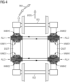
- FIG 4 shows two wheel sets RS1, RS2 of a rail vehicle, which are connected in a known manner to a bogie DGST of a rail vehicle via hydraulic axle guide bearings ALL1 to ALL4.
- the first wheelset RS1 is connected to the bogie DGST via two hydraulic axle guide bearings ALL1 and ALL2, which have external connections and are designed as described above.
- a first axle guide bearing ALL1 has two diametrically opposed chambers KAM11, KAM12, which are referred to as the first chamber KAM11 and the second chamber KAM12, respectively.
- the second chamber KAM12 is arranged in front of the first chamber KAM11.
- a second axle guide bearing ALL2 has two diametrically opposed chambers KAM21, KAM22, which are referred to as the first chamber KAM21 and the second chamber KAM22, respectively.
- the second chamber KAM22 is arranged in front of the first chamber KAM21.
- the first chamber KAM11 of the first axle guide bearing ALL1 is connected to the first chamber KAM21 of the second axle guide bearing ALL2 for fluid exchange via external connections.
- the second chamber KAM12 of the first axle guide bearing ALL1 is connected to the second chamber KAM22 of the second axle guide bearing ALL2 for fluid exchange via external connections.
- the second wheelset RS2 is connected to the bogie DGST via two hydraulic axle guide bearings ALL3 and ALL4, which have external connections and are designed as described above.
- a first axle guide bearing ALL3 has two diametrically opposed chambers KAM31, KAM32, which are referred to as the first chamber KAM31 and the second chamber KAM32, respectively.
- the first chamber KAM31 is arranged in front of the second chamber KAM32.
- a second axle guide bearing ALL4 has two diametrically opposed chambers KAM41, KAM42, which are referred to as the first chamber KAM41 and the second chamber KAM42, respectively.
- the first chamber KAM41 is arranged in front of the second chamber KAM21.
- the first chamber KAM31 of the first axle guide bearing ALL3 is connected to the first chamber KAM41 of the second axle guide bearing ALL4 for fluid exchange via external connections.
- the second chamber KAM32 of the first axle guide bearing ALL3 is connected to the second chamber KAM42 of the second axle guide bearing ALL4 for fluid exchange via external connections.
- the invention relates to an arrangement for transmitting longitudinal forces in a rail vehicle, with a hydraulic axle guide bearing, with a wheel set and with a bogie of the rail vehicle.
- the hydraulic axle guide bearing has an outer housing element and an inner housing element, wherein one of the housing elements is connected to the bogie, while the other housing element is connected to the wheelset. Longitudinal forces generated by the rail vehicle during travel are thereby transferred between the wheelset and the bogie.
- the outer housing element encloses the inner housing element at a radial distance so that an annular gap is formed.
- An elastic element is arranged in the annular gap in such a way that it forms two opposing chambers with respective chamber volumes.
- the longitudinal forces cause a change in the relative position of the inner housing element to the outer housing element, which causes an alternating volume change of the two chambers.
- the two chambers contain a fluid and are coupled to one another via the fluid in such a way that the movement of the fluid causes the alternating volume change of the two chambers.
- the coupling of the two chambers is achieved by the fluid via two external connections of the axle guide bearing and via an external line that connects the two connections to one another.
- the external line has a damping element that divides the external line into two.
- the damping element is designed in such a way that a movement of the fluid caused by the longitudinal forces, which causes the alternating volume change of the two chambers, is dampened.
- the damping element also introduces or influences stiffness into the system.
- a first chamber is connected to a first connection via a first channel that runs inside the inner housing element.
- the first connection is arranged as part of the inner housing element in the outer region of the axle guide bearing.
- a second chamber is connected to a second port via a second channel that runs inside the inner housing element.
- the second port is arranged as part of the inner housing element in the outer region of the axle guide bearing.
- the damping element is designed as a cylinder filled with the fluid with an integrated piston.
- the cylinder has a total cylinder volume that is divided into a first cylinder partial volume and a second cylinder partial volume via the movably mounted piston, so that depending on the direction of movement of the fluid in the cylinder, the piston causes an alternating volume change in the first cylinder partial volume and the second cylinder partial volume.
- the first cylinder sub-volume is connected to a first connection of the axle guide bearing, while the second cylinder sub-volume is connected to a second connection of the axle guide bearing.
- the piston is coupled to a spring and a damper connected in parallel to dampen the movement of the piston caused by the movement of the fluid.
- the spring and the damper are used to set the desired damping.
- the present invention transforms unstable eigenmodes of the rail vehicle into stable eigenmodes.
- the present invention enables increased driving speeds to be achieved with high levels of safety.
- the present invention increases the driving stability of the rail vehicle.
- the present invention uses the two lines to ensure that the damping element can be positioned at any location on the rail vehicle.
- the present invention or the damping element connected via external lines makes it possible to advantageously arrange this damping element at a location with sufficiently large installation space and thus, if necessary, also away from the axle guide bearings.
- the individual stiffnesses of the axle guide bearings and the individual dampings of the axle guide bearings as well as the damping in the hydraulic system result in an overall stiffness and an overall damping.
- the present invention suitable or optimal parameter ranges for stiffness and damping are achieved.
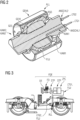
- FIG 1 shows a hydraulic axle guide bearing ALL with external connections ANSCHL1, ANSCHL2, which forms an essential element of the present invention
- FIG 2 a cross-sectional view of the FIG 1 shown hydraulic axle guide bearing ALL.
- the axle guide bearing ALL has two external connections ANSCHL1, ANSCHL2, to which the respective connecting lines LTG1, LTG2 are attached.
- the axle guide bearing ALL has an outer housing element GEHA and an inner housing element GEHI as a hydraulic bush.
- the outer housing element GEHA encloses the inner housing element GEHI at a radial distance so that an annular gap RGS is formed.
- a (rubber) elastic element GEE is arranged in such a way that it forms and delimits two diametrically opposed chambers KAM1, KAM2.
- the elastic element GEE enables a volume change of the two chambers KAM1, KAM2.
- a first chamber KAM1 which is filled with a hydraulic fluid FLU.
- the first chamber KAM1 is connected to the first connection ANSCHL1 via a first channel KAN1, which runs inside the inner housing element GEHI.
- the first connection ANSCHL1 is part of the inner housing element GEHI and is located in the outer area of the axle guide bearing ALL.
- a second chamber KAM2 which is only indicated here and which is located opposite the first chamber KAM1, i.e. is arranged diametrically opposite it.
- the second chamber KAM2 is filled with the hydraulic fluid FLU.
- the second chamber KAM2 is connected to the second connection ANSCHL2 via a second channel KAN2, which also runs inside the inner housing element GEHI.
- the second connection ANSCHL2 is part of the inner housing element GEHI and is located in the outer area of the axle guide bearing ALL.
- FIG 3 shows with reference to FIG 1 and FIG 2 the arrangement according to the invention for transmitting longitudinal forces in a rail vehicle.
- the axle guide bearing ALL has a first external connection ANSCHL1 and a second external connection ANSCHL2, to which the first line LTG1 and the second line LTG2 are connected, respectively.
- the two chambers KAM1, KAM2 are variable in volume and each contain the fluid FLU.
- the fluid FLU of the first chamber KAM1 acts on a damping element FDE via the first connection ANSCHL1 and the subsequent first line LTG1.
- the fluid FLU of the second chamber KAM2 also acts on the damping element FDE via the second connection ANSCHL2 and the subsequent second line LTG2.
- the damping element FDE is connected and designed between the two lines in such a way that the direction of movement of the fluid FLU of both chambers KAM1, KAM2 and thus the volume change of the two chambers KAM1, KAM2 is dampened and, if necessary, delayed.
- the longitudinal or transverse stiffness of the hydraulic axle guide bearing ALL is adjusted via the damped or time-delayed volume change.
- the two lines LTG1 and LTG2 advantageously enable the damping element FDE to be positioned at any point on the rail vehicle.
- the damping element FDE is shown as an example as a cylinder ZYL with an integrated piston STP, whereby the piston STP acts on a spring FD and on a damper DE, which is connected in parallel to the spring FD.
- the cylinder ZYL has a total cylinder volume, which is divided into a first cylinder partial volume and a second cylinder partial volume via the movably mounted piston STP.
- the first cylinder partial volume is increased when the second cylinder partial volume is reduced, and vice versa.
- the fluid FLU of the first chamber KAM1 or the first line LTG1 acts on a first side of the piston STP, while the fluid of the second chamber KAM2 or the second line LTG2 acts on a second side of the piston STP, which is opposite the first side.
- the direction of movement of the piston STP is determined by a pressure difference of the fluid FLU in the two lines LTG1, LTG2 or in the two chambers KAM1, KAM2.
Landscapes
- Engineering & Computer Science (AREA)
- General Engineering & Computer Science (AREA)
- Mechanical Engineering (AREA)
- Combined Devices Of Dampers And Springs (AREA)
- Fluid-Damping Devices (AREA)
- Vehicle Body Suspensions (AREA)
Applications Claiming Priority (2)
| Application Number | Priority Date | Filing Date | Title |
|---|---|---|---|
| DE102020216073.2A DE102020216073A1 (de) | 2020-12-16 | 2020-12-16 | Anordnung zur Übertragung von Längskräften bei einem Schienenfahrzeug |
| PCT/EP2021/081987 WO2022128299A1 (de) | 2020-12-16 | 2021-11-17 | Anordnung zur übertragung von längskräften bei einem schienenfahrzeug |
Publications (2)
| Publication Number | Publication Date |
|---|---|
| EP4237307A1 EP4237307A1 (de) | 2023-09-06 |
| EP4237307B1 true EP4237307B1 (de) | 2025-01-01 |
Family
ID=78820735
Family Applications (1)
| Application Number | Title | Priority Date | Filing Date |
|---|---|---|---|
| EP21819043.7A Active EP4237307B1 (de) | 2020-12-16 | 2021-11-17 | Anordnung zur übertragung von längskräften bei einem schienenfahrzeug |
Country Status (6)
| Country | Link |
|---|---|
| EP (1) | EP4237307B1 (pl) |
| CN (1) | CN116583418B (pl) |
| DE (1) | DE102020216073A1 (pl) |
| ES (1) | ES3021460T3 (pl) |
| PL (1) | PL4237307T3 (pl) |
| WO (1) | WO2022128299A1 (pl) |
Families Citing this family (1)
| Publication number | Priority date | Publication date | Assignee | Title |
|---|---|---|---|---|
| DE102024208626A1 (de) * | 2024-09-11 | 2026-03-12 | Siemens Mobility GmbH | Hydraulisch angekoppelte Schwingungstilgung |
Family Cites Families (11)
| Publication number | Priority date | Publication date | Assignee | Title |
|---|---|---|---|---|
| DE3331559A1 (de) * | 1983-09-01 | 1985-03-28 | Thyssen Industrie Ag, 4300 Essen | Achssteuerung fuer schienenfahrzeuge |
| JPS63231032A (ja) * | 1987-03-16 | 1988-09-27 | Toyota Motor Corp | 流体入りブツシユ |
| ES2228090T3 (es) | 1999-08-31 | 2005-04-01 | Construcciones Y Auxiliar De Ferrocarriles S.A. Caf. | Dispositivo de guiado de los ejes de un vehiculo ferroviario. |
| AU2002953153A0 (en) * | 2002-12-06 | 2002-12-19 | Kinetic Pty Limited | Hydraulic suspension system |
| DE10310634A1 (de) | 2003-03-10 | 2004-09-30 | Carl Freudenberg Kg | Achslenkerlager |
| ES2750362T3 (es) | 2013-01-30 | 2020-03-25 | Bombardier Transp Gmbh | Tren de rodaje con unidad de rueda dirigida |
| DE102013103827A1 (de) | 2013-04-16 | 2014-10-16 | Bombardier Transportation Gmbh | Fahrwerk mit quergekoppelten Radeinheiten |
| DE102013224582A1 (de) * | 2013-11-29 | 2015-06-03 | Siemens Aktiengesellschaft | Fahrwerk für ein Schienenfahrzeug |
| DE102014214055A1 (de) * | 2014-07-18 | 2016-01-21 | Siemens Aktiengesellschaft | Fahrwerk für ein Schienenfahrzeug |
| AT519394B1 (de) | 2016-11-24 | 2023-01-15 | Siemens Mobility Austria Gmbh | Radsteuerungsanordnung für ein Fahrwerk |
| DE102018200344A1 (de) * | 2018-01-11 | 2019-07-11 | Contitech Luftfedersysteme Gmbh | Hydraulische Lagerbuchse |
-
2020
- 2020-12-16 DE DE102020216073.2A patent/DE102020216073A1/de not_active Withdrawn
-
2021
- 2021-11-17 CN CN202180084471.3A patent/CN116583418B/zh active Active
- 2021-11-17 ES ES21819043T patent/ES3021460T3/es active Active
- 2021-11-17 EP EP21819043.7A patent/EP4237307B1/de active Active
- 2021-11-17 PL PL21819043.7T patent/PL4237307T3/pl unknown
- 2021-11-17 WO PCT/EP2021/081987 patent/WO2022128299A1/de not_active Ceased
Also Published As
| Publication number | Publication date |
|---|---|
| CN116583418A (zh) | 2023-08-11 |
| ES3021460T3 (en) | 2025-05-27 |
| CN116583418B (zh) | 2025-12-19 |
| EP4237307A1 (de) | 2023-09-06 |
| DE102020216073A1 (de) | 2022-06-23 |
| WO2022128299A1 (de) | 2022-06-23 |
| PL4237307T3 (pl) | 2025-06-09 |
Similar Documents
| Publication | Publication Date | Title |
|---|---|---|
| DE69931859T2 (de) | Fahrzeugaufhängungsvorrichtung | |
| DE60013732T2 (de) | Radaufhängungssystem für ein Fahrzeug | |
| DE69101803T2 (de) | Verbesserungen zu hydraulischen Antischwingungsbuchsen. | |
| DE102017218905B4 (de) | Feder-Dämpfersystem mit variabler Federrate | |
| DE10126555A1 (de) | Dämpfungskraftregelnder Hydraulikstoßdämpfer | |
| DE69920527T2 (de) | Vorrichtung zur steuerung der achsen eines schienenfahrzeuges | |
| AT518973B1 (de) | Fahrwerk für ein Schienenfahrzeug | |
| EP4081414B1 (de) | Ansteuervorrichtung | |
| DE102013224582A1 (de) | Fahrwerk für ein Schienenfahrzeug | |
| EP2986482A1 (de) | Fahrwerk mit quergekoppelten radeinheiten | |
| EP4237307B1 (de) | Anordnung zur übertragung von längskräften bei einem schienenfahrzeug | |
| EP4237308B1 (de) | Anordnung zur übertragung von längskräften bei einem schienenfahrzeug | |
| EP2065286B1 (de) | Schienenfahrzeug sowie Verfahren zur Kopplung von Drehgestellen eines Schienenfahrzeuges | |
| EP3384178B1 (de) | Hydraulische lagerbuchse | |
| DE4343608C2 (de) | Anordnung zur Übertragung von Bewegungen und Kräften zwischen Bauteilen insbesondere von Schienenfahrzeugen | |
| DE102020210809A1 (de) | Stoßdämpfer mit hydraulischem Druckanschlag sowie Fahrzeug | |
| EP3978330B1 (de) | Elastikelement und fahrwerk | |
| DE102004051601A1 (de) | Wankstabilisierungssystem für ein zweispuriges Fahrzeug | |
| DE102023107421A1 (de) | Dämpfungssystem und Kraftfahrzeug | |
| DE102009020249A1 (de) | Anordnung zur Fahrwerksstabilisierung | |
| DE102008045537A1 (de) | Servoventil | |
| EP2353961A1 (de) | Fahrwerk für ein Schienenfahrzeug | |
| DE102018206940B4 (de) | Verbund-Blattfeder mit hydraulischem Buchsenelement | |
| EP4227188A1 (de) | Schienenfahrzeugfahrwerk mit einer vorrichtung zum steuern einer radachse | |
| EP4299947A1 (de) | Fluidische koppelvorrichtung und fahrwerk |
Legal Events
| Date | Code | Title | Description |
|---|---|---|---|
| STAA | Information on the status of an ep patent application or granted ep patent |
Free format text: STATUS: UNKNOWN |
|
| STAA | Information on the status of an ep patent application or granted ep patent |
Free format text: STATUS: THE INTERNATIONAL PUBLICATION HAS BEEN MADE |
|
| PUAI | Public reference made under article 153(3) epc to a published international application that has entered the european phase |
Free format text: ORIGINAL CODE: 0009012 |
|
| STAA | Information on the status of an ep patent application or granted ep patent |
Free format text: STATUS: REQUEST FOR EXAMINATION WAS MADE |
|
| 17P | Request for examination filed |
Effective date: 20230601 |
|
| AK | Designated contracting states |
Kind code of ref document: A1 Designated state(s): AL AT BE BG CH CY CZ DE DK EE ES FI FR GB GR HR HU IE IS IT LI LT LU LV MC MK MT NL NO PL PT RO RS SE SI SK SM TR |
|
| DAV | Request for validation of the european patent (deleted) | ||
| DAX | Request for extension of the european patent (deleted) | ||
| GRAP | Despatch of communication of intention to grant a patent |
Free format text: ORIGINAL CODE: EPIDOSNIGR1 |
|
| STAA | Information on the status of an ep patent application or granted ep patent |
Free format text: STATUS: GRANT OF PATENT IS INTENDED |
|
| INTG | Intention to grant announced |
Effective date: 20240828 |
|
| GRAS | Grant fee paid |
Free format text: ORIGINAL CODE: EPIDOSNIGR3 |
|
| GRAA | (expected) grant |
Free format text: ORIGINAL CODE: 0009210 |
|
| STAA | Information on the status of an ep patent application or granted ep patent |
Free format text: STATUS: THE PATENT HAS BEEN GRANTED |
|
| AK | Designated contracting states |
Kind code of ref document: B1 Designated state(s): AL AT BE BG CH CY CZ DE DK EE ES FI FR GB GR HR HU IE IS IT LI LT LU LV MC MK MT NL NO PL PT RO RS SE SI SK SM TR |
|
| REG | Reference to a national code |
Ref country code: GB Ref legal event code: FG4D Free format text: NOT ENGLISH |
|
| REG | Reference to a national code |
Ref country code: DE Ref legal event code: R096 Ref document number: 502021006306 Country of ref document: DE |
|
| REG | Reference to a national code |
Ref country code: CH Ref legal event code: EP |
|
| REG | Reference to a national code |
Ref country code: IE Ref legal event code: FG4D Free format text: LANGUAGE OF EP DOCUMENT: GERMAN |
|
| REG | Reference to a national code |
Ref country code: LT Ref legal event code: MG9D |
|
| REG | Reference to a national code |
Ref country code: NL Ref legal event code: MP Effective date: 20250101 |
|
| REG | Reference to a national code |
Ref country code: ES Ref legal event code: FG2A Ref document number: 3021460 Country of ref document: ES Kind code of ref document: T3 Effective date: 20250527 |
|
| PG25 | Lapsed in a contracting state [announced via postgrant information from national office to epo] |
Ref country code: NL Free format text: LAPSE BECAUSE OF FAILURE TO SUBMIT A TRANSLATION OF THE DESCRIPTION OR TO PAY THE FEE WITHIN THE PRESCRIBED TIME-LIMIT Effective date: 20250101 |
|
| PG25 | Lapsed in a contracting state [announced via postgrant information from national office to epo] |
Ref country code: FI Free format text: LAPSE BECAUSE OF FAILURE TO SUBMIT A TRANSLATION OF THE DESCRIPTION OR TO PAY THE FEE WITHIN THE PRESCRIBED TIME-LIMIT Effective date: 20250101 |
|
| PG25 | Lapsed in a contracting state [announced via postgrant information from national office to epo] |
Ref country code: IS Free format text: LAPSE BECAUSE OF FAILURE TO SUBMIT A TRANSLATION OF THE DESCRIPTION OR TO PAY THE FEE WITHIN THE PRESCRIBED TIME-LIMIT Effective date: 20250501 Ref country code: NO Free format text: LAPSE BECAUSE OF FAILURE TO SUBMIT A TRANSLATION OF THE DESCRIPTION OR TO PAY THE FEE WITHIN THE PRESCRIBED TIME-LIMIT Effective date: 20250401 |
|
| PG25 | Lapsed in a contracting state [announced via postgrant information from national office to epo] |
Ref country code: HR Free format text: LAPSE BECAUSE OF FAILURE TO SUBMIT A TRANSLATION OF THE DESCRIPTION OR TO PAY THE FEE WITHIN THE PRESCRIBED TIME-LIMIT Effective date: 20250101 |
|
| PG25 | Lapsed in a contracting state [announced via postgrant information from national office to epo] |
Ref country code: PT Free format text: LAPSE BECAUSE OF FAILURE TO SUBMIT A TRANSLATION OF THE DESCRIPTION OR TO PAY THE FEE WITHIN THE PRESCRIBED TIME-LIMIT Effective date: 20250502 Ref country code: LV Free format text: LAPSE BECAUSE OF FAILURE TO SUBMIT A TRANSLATION OF THE DESCRIPTION OR TO PAY THE FEE WITHIN THE PRESCRIBED TIME-LIMIT Effective date: 20250101 |
|
| PG25 | Lapsed in a contracting state [announced via postgrant information from national office to epo] |
Ref country code: GR Free format text: LAPSE BECAUSE OF FAILURE TO SUBMIT A TRANSLATION OF THE DESCRIPTION OR TO PAY THE FEE WITHIN THE PRESCRIBED TIME-LIMIT Effective date: 20250402 Ref country code: BG Free format text: LAPSE BECAUSE OF FAILURE TO SUBMIT A TRANSLATION OF THE DESCRIPTION OR TO PAY THE FEE WITHIN THE PRESCRIBED TIME-LIMIT Effective date: 20250101 |
|
| REG | Reference to a national code |
Ref country code: DE Ref legal event code: R081 Ref document number: 502021006306 Country of ref document: DE Owner name: SIEMENS MOBILITY GMBH, DE Free format text: FORMER OWNER: SIEMENS MOBILITY GMBH, 81739 MUENCHEN, DE |
|
| PG25 | Lapsed in a contracting state [announced via postgrant information from national office to epo] |
Ref country code: SE Free format text: LAPSE BECAUSE OF FAILURE TO SUBMIT A TRANSLATION OF THE DESCRIPTION OR TO PAY THE FEE WITHIN THE PRESCRIBED TIME-LIMIT Effective date: 20250101 |
|
| REG | Reference to a national code |
Ref country code: DE Ref legal event code: R097 Ref document number: 502021006306 Country of ref document: DE |
|
| PG25 | Lapsed in a contracting state [announced via postgrant information from national office to epo] |
Ref country code: SM Free format text: LAPSE BECAUSE OF FAILURE TO SUBMIT A TRANSLATION OF THE DESCRIPTION OR TO PAY THE FEE WITHIN THE PRESCRIBED TIME-LIMIT Effective date: 20250101 |
|
| RAP4 | Party data changed (patent owner data changed or rights of a patent transferred) |
Owner name: SIEMENS MOBILITY GMBH |
|
| PG25 | Lapsed in a contracting state [announced via postgrant information from national office to epo] |
Ref country code: DK Free format text: LAPSE BECAUSE OF FAILURE TO SUBMIT A TRANSLATION OF THE DESCRIPTION OR TO PAY THE FEE WITHIN THE PRESCRIBED TIME-LIMIT Effective date: 20250101 |
|
| PG25 | Lapsed in a contracting state [announced via postgrant information from national office to epo] |
Ref country code: IT Free format text: LAPSE BECAUSE OF FAILURE TO SUBMIT A TRANSLATION OF THE DESCRIPTION OR TO PAY THE FEE WITHIN THE PRESCRIBED TIME-LIMIT Effective date: 20250101 |
|
| PG25 | Lapsed in a contracting state [announced via postgrant information from national office to epo] |
Ref country code: EE Free format text: LAPSE BECAUSE OF FAILURE TO SUBMIT A TRANSLATION OF THE DESCRIPTION OR TO PAY THE FEE WITHIN THE PRESCRIBED TIME-LIMIT Effective date: 20250101 |
|
| PG25 | Lapsed in a contracting state [announced via postgrant information from national office to epo] |
Ref country code: RO Free format text: LAPSE BECAUSE OF FAILURE TO SUBMIT A TRANSLATION OF THE DESCRIPTION OR TO PAY THE FEE WITHIN THE PRESCRIBED TIME-LIMIT Effective date: 20250101 |
|
| PG25 | Lapsed in a contracting state [announced via postgrant information from national office to epo] |
Ref country code: SK Free format text: LAPSE BECAUSE OF FAILURE TO SUBMIT A TRANSLATION OF THE DESCRIPTION OR TO PAY THE FEE WITHIN THE PRESCRIBED TIME-LIMIT Effective date: 20250101 |
|
| PLBE | No opposition filed within time limit |
Free format text: ORIGINAL CODE: 0009261 |
|
| STAA | Information on the status of an ep patent application or granted ep patent |
Free format text: STATUS: NO OPPOSITION FILED WITHIN TIME LIMIT |
|
| REG | Reference to a national code |
Ref country code: CH Ref legal event code: L10 Free format text: ST27 STATUS EVENT CODE: U-0-0-L10-L00 (AS PROVIDED BY THE NATIONAL OFFICE) Effective date: 20251112 |
|
| 26N | No opposition filed |
Effective date: 20251002 |
|
| PGFP | Annual fee paid to national office [announced via postgrant information from national office to epo] |
Ref country code: AT Payment date: 20260113 Year of fee payment: 5 |
|
| PGFP | Annual fee paid to national office [announced via postgrant information from national office to epo] |
Ref country code: FR Payment date: 20251114 Year of fee payment: 5 |
|
| PGFP | Annual fee paid to national office [announced via postgrant information from national office to epo] |
Ref country code: CZ Payment date: 20251111 Year of fee payment: 5 |
|
| PGFP | Annual fee paid to national office [announced via postgrant information from national office to epo] |
Ref country code: PL Payment date: 20251106 Year of fee payment: 5 |
|
| REG | Reference to a national code |
Ref country code: CH Ref legal event code: U11 Free format text: ST27 STATUS EVENT CODE: U-0-0-U10-U11 (AS PROVIDED BY THE NATIONAL OFFICE) Effective date: 20260209 |