EP4237262B1 - Reifen mit einer überwachungsvorrichtung - Google Patents
Reifen mit einer überwachungsvorrichtung Download PDFInfo
- Publication number
- EP4237262B1 EP4237262B1 EP21806417.8A EP21806417A EP4237262B1 EP 4237262 B1 EP4237262 B1 EP 4237262B1 EP 21806417 A EP21806417 A EP 21806417A EP 4237262 B1 EP4237262 B1 EP 4237262B1
- Authority
- EP
- European Patent Office
- Prior art keywords
- adhesive
- tyre
- region
- housing portion
- monitoring device
- Prior art date
- Legal status (The legal status is an assumption and is not a legal conclusion. Google has not performed a legal analysis and makes no representation as to the accuracy of the status listed.)
- Active
Links
Images
Classifications
-
- B—PERFORMING OPERATIONS; TRANSPORTING
- B60—VEHICLES IN GENERAL
- B60C—VEHICLE TYRES; TYRE INFLATION; TYRE CHANGING; CONNECTING VALVES TO INFLATABLE ELASTIC BODIES IN GENERAL; DEVICES OR ARRANGEMENTS RELATED TO TYRES
- B60C23/00—Devices for measuring, signalling, controlling, or distributing tyre pressure or temperature, specially adapted for mounting on vehicles; Arrangement of tyre inflating devices on vehicles, e.g. of pumps or of tanks; Tyre cooling arrangements
- B60C23/02—Signalling devices actuated by tyre pressure
- B60C23/04—Signalling devices actuated by tyre pressure mounted on the wheel or tyre
- B60C23/0491—Constructional details of means for attaching the control device
- B60C23/0493—Constructional details of means for attaching the control device for attachment on the tyre
-
- B—PERFORMING OPERATIONS; TRANSPORTING
- B29—WORKING OF PLASTICS; WORKING OF SUBSTANCES IN A PLASTIC STATE IN GENERAL
- B29D—PRODUCING PARTICULAR ARTICLES FROM PLASTICS OR FROM SUBSTANCES IN A PLASTIC STATE
- B29D30/00—Producing pneumatic or solid tyres or parts thereof
- B29D30/005—General arrangement or lay-out of plants for the processing of tyres or parts thereof
-
- B—PERFORMING OPERATIONS; TRANSPORTING
- B29—WORKING OF PLASTICS; WORKING OF SUBSTANCES IN A PLASTIC STATE IN GENERAL
- B29D—PRODUCING PARTICULAR ARTICLES FROM PLASTICS OR FROM SUBSTANCES IN A PLASTIC STATE
- B29D30/00—Producing pneumatic or solid tyres or parts thereof
- B29D30/0061—Accessories, details or auxiliary operations not otherwise provided for
- B29D2030/0072—Attaching fasteners to tyres, e.g. patches, in order to connect devices to tyres
-
- B—PERFORMING OPERATIONS; TRANSPORTING
- B60—VEHICLES IN GENERAL
- B60C—VEHICLE TYRES; TYRE INFLATION; TYRE CHANGING; CONNECTING VALVES TO INFLATABLE ELASTIC BODIES IN GENERAL; DEVICES OR ARRANGEMENTS RELATED TO TYRES
- B60C19/00—Tyre parts or constructions not otherwise provided for
- B60C2019/004—Tyre sensors other than for detecting tyre pressure
Definitions
- the present invention relates to a tyre comprising a monitoring device.
- a tyre has a substantially toroidal structure around an axis of rotation thereof during operation, and it has an equatorial plane perpendicular to the axis of rotation, said equatorial plane being typically a plane of (substantial) geometric symmetry (e.g. neglecting any minor asymmetries, such as the tread design and/or the writings on the sides and/or the internal structure).
- inner cavity it is meant the space delimited by the inner surface of tyre and by the surface of the mounting rim facing towards the inner surface of the tyre, when mounted.
- 'crown portion it is meant the portion of tyre placed at the tread band.
- radial and axial are used with reference respectively to a direction perpendicular and to a direction parallel to the axis of rotation of the tyre.
- tangential is used with reference to a direction generally oriented according to the rolling direction of the tyre, perpendicular to both the radial direction and the axial direction.
- footprint it is meant the portion of outer surface of the tread band (and by extension the part of crown portion corresponding to such portion of surface) which, during the rolling of the tyre mounted and subjected to a load (for example due the mounting under a vehicle), is in instant contact with the rolling surface.
- the footprint typically has substantially null curvature (or substantially infinite radius of curvature), or in any case it substantially assumes the conformation of the rolling surface.
- monitoring devices fixed to the inner surface of a tyre at the crown portion for detecting one or more physical quantities of the tyre, such as for example temperature, pressure, acceleration of the inner surface, deformation of the inner surface, etc.
- the document WO2018/065846A1 discloses a device for securing an electronic unit to a tyre, the device comprising a base formed by elastomeric material on which a module comprising the electronic unit is stably fixed.
- the lower surface of the base intended for being glued to the tyre's surface, is coated by means of a pressure sensitive adhesive.
- WO2019/123118A1 discloses a tyre monitoring device comprising an electronic unit enclosed in an encapsulation material.
- the encapsulation material forms a single body comprising an upper portion, in which the electronic unit is enclosed, and a lower portion, comprising a base surface intended for fixing the device to the inner surface of the tyre.
- the document DE102007001279A1 discloses a tyre and an electronic module arranged on an inner side of the tyre and in which electronic components are embedded.
- the electronic module consists of two different sealing compounds which exhibit different physical characteristics.
- a first sealing compound is connected with the inner side of the tyre by an adhesive layer and it consists of a soft material and a second sealing compound consists of a hard material.
- the electronic components are embedded into both the sealing compounds.
- the document DE102007030238A1 discloses a pneumatic vehicle tyre with an electronic module.
- the Applicant has faced the problem of reaching, with such tyres, higher and higher speeds, even up to the maximum homologation speed of the tyre (typically higher than 300 km/h or even higher than 350 km/h).
- the Applicant has observed, after tests performed both in laboratory and on track, that the known monitoring devices, when used at the aforesaid very high speeds, undergo various problems, including the possible detachment from the tyre, with consequent damage and/o destruction of the device and/or tyre and loss of functionality.
- the radial acceleration to which the monitoring device is subjected is greater than in the out-of-footprint regions. It follows that the radial acceleration of the monitoring device undergoes a rapid and cyclical variation at high frequency, which in turn generates a corresponding cyclic variation of the radial force acting on the monitoring device.
- the Applicant believes that this imbalance in the radial forces, together with their cyclic variation at the entry and exit from the footprint, affects - in particular at very high speeds - the layer of adhesive that secures the device to the tyre. In fact, it is believed that the adhesive located at the substantially central portion of the device undergoes more intense radial stretching and compression cycles than the adhesive located at the peripheral portion of the device. The Applicant believes that this phenomenon generates a sort of "pumping" on the adhesive which induces a migration thereof from the centre towards the periphery of the gluing surface, where it accumulates.
- the Applicant has first tried to increase the thickness of the glue, to increase the possibility of the glue itself to stretch.
- the Applicant has not observed appreciable improvements.
- this increase of thickness increases, at the same time, the local temperature of the tyre, risking to compromise the integrity of the tyre and/or of the monitoring device.
- PSA pressure sensitive adhesives
- This high viscous component brings a great heat development as a consequence of cyclic stress.
- the Applicant has found that it is possible to maintain a firm fixing of a monitoring device even at very high speeds by applying the layer of adhesive in a spatially selective manner on the gluing surface, namely removing a part of the adhesive, as described below.
- the invention relates to a tyre comprising a monitoring device according to claim 1.
- the monitoring device comprises a housing portion and a base portion mutually integral, said base portion having a coupling surface in single-piece intended for fixing the monitoring device to the tyre, wherein a projection of said housing portion onto said coupling surface has an extension lower than said coupling surface.
- the monitoring device comprises an electronic unit housed in said housing portion.
- the monitoring device is fixed to an inner surface of said tyre at a crown portion of said tyre by an adhesive interposed between said coupling surface and said inner surface.
- a first region of said coupling surface is covered by said adhesive and a second region of said coupling surface, complementary to said first region, is free of adhesive.
- Said second region is contained within said projection of said housing portion onto said coupling surface.
- the Applicant has realized that the fact that a region of the coupling surface contained within a projection of the housing portion (which contains the electronic unit) on the coupling surface itself is free of adhesive, allows to reduce the amount of adhesive precisely at the region of the coupling surface in which the adhesive itself would be subjected in a more intense way to the aforesaid radial stretching and compression cycles.
- the aforementioned "pumping" and migration phenomena of the adhesive are thus reduced, and even eliminated, preventing the accumulation of important portions of adhesive in the peripheral region of the coupling surface and therefore mitigating or eliminating the variation in the adhesion properties of the device to the tyre and the onset of consequent localized stresses and/or of excessive temperature increase.
- the Applicant has found that in this way it is possible to obtain a stable gluing of the monitoring device to the inner surface of the tyre even at the maximum homologation speed of the tyre, without detachment of the device itself and/or without an excessive increase in the local temperature which could damage the tyre or the electronics of the device itself.
- the present invention can have one or more of the following preferred features.
- Preferably said first region entirely surrounds said second region.
- said first region is continuous and/or said second region is continuous.
- said housing portion is arranged in (substantially) central position of said base portion, more preferably of said coupling surface. In this way the device is balanced and the stability of the device once glued is increased.
- a projection of a centre of mass of said housing portion onto said coupling surface falls in a central position of said second region.
- the region free of adhesive is arranged in rational way with respect to the zone with greatest mass concentration of the device.
- said second region is arranged in (substantially) central position of said projection of said housing portion.
- the housing portion has at least axial symmetry and mass substantially equally distributed around the axis of symmetry (to limit and/or avoid imbalances and/or the onset of force momenta on the device during the rotation of the tyre).
- said second region has a plan extension greater than or equal to 45%, more preferably greater than or equal to 55%, of said projection of the housing portion.
- said second region has a plan extension less than or equal to 95%, more preferably less than or equal to 85%, of said projection of the housing portion.
- said second region reproduces, with a scale factor, a shape of said projection of the housing portion.
- the second region adapts itself to the geometry of the housing portion, with a substantial uniformity of distribution of the adhesive.
- a distance measured along the coupling surface between an edge of said second region and an ideal edge of said projection of said housing portion is equal to at least 1 mm, more preferably to at least 2 mm, along an entire development of said edge of the second region.
- on the coupling surface there is at least 1 millimetre of adhesive between the ideal edge of the projection of the housing portion on the coupling surface and the beginning of the second region.
- ideal edge of the projection of the housing portion it is meant the projection of the entire housing portion considered in its maximum encumbrance.
- said distance is at most 5 mm.
- said adhesive is a pressure sensitive adhesive (PSA).
- PSA pressure sensitive adhesive
- the pressure sensitive adhesive can be an acrylic adhesive, a silicone adhesive, a butyl adhesive, a natural rubber-based adhesive or a block copolymer-based adhesive.
- the material of the adhesive can be reinforced by adding fibres.
- Said adhesive has a, preferably uniform, thickness less than or equal to 200 ⁇ m, more preferably less than or equal to 150 ⁇ m.
- the Applicant has experimentally observed that these thicknesses, reduced with respect to the thicknesses typically used (equal to about 300 ⁇ m), considerably mitigate the problem of damage of the sensor and/or of the tyre due to overheating, for example in terms of increasing the time lapsed before the fault occurs, as better explained below.
- said housing portion comprises a rigid body suitable for housing said electronic unit.
- the rigid body can be made of plastic material, and/or by means of resins (e.g. epoxy or polyurethane resin), and/or of sufficiently rigid elastomeric material.
- said projection of the housing portion coincides with a projection of the rigid body (considered in its maximum encumbrance).
- said base portion has a perimetral edge free of corners, cusps and/or portion with small curvature radii.
- said base portion has a circular or oval perimetral edge. This allows to reduce the onset of cracks due to the concentration of stresses in the corners or in any case at the portions with small curvature radii. The onset of trigger points for localized detachments is also reduced.
- said base portion has a perimetral edge with wavelike trend along a (substantially) circular or oval generating line.
- said housing portion more preferably said rigid body, has substantially cylindrical or prismatic shape.
- said base portion comprises a plurality of reinforcing elements.
- said reinforcing elements can comprise textile or metallic filaments or cords, for example made of one or more of the following textile materials: aramid, rayon, polyester, nylon, lyocell.
- the expression "one or more textile materials” comprises the case in which only one material is used for all the textile cords or filaments used in the base portion, or the case in which in the base portion more materials are used within mixed filaments or cords (for example filaments or cords of one material alternated with filaments or cords of another material), or the case in which in the base portion multiple materials are used in hybrid filaments or cords (for example cords comprising filaments of two different materials).
- the reinforcing elements can also be made by, or can comprise, metal (possibly hybrid metal/textile) filaments or cords, for example thin steel wires.
- metal possibly hybrid metal/textile
- said reinforcing elements are arranged with a density comprised between 30 cords/dm and 500 cords/dm.
- said monitoring device comprises an encapsulation material which at least partially encloses said electronic unit. In this way the electronic unit is further protected.
- said encapsulation material is a polyurethane material or a polyurea.
- said polyurethane material can be a polyether-based polyurethane material.
- said encapsulation material realizes with continuity at least part of said housing portion (e.g. it at least partially fills the rigid body) and at least part of said base portion (in particular said coupling surface) to make said housing portion and said base portion mutually integral. More preferably said encapsulation material entirely realizes said base portion (and said coupling surface). In this way, the two portions are made in single piece, to the advantage of a firm interconnection between the two portions.
- said reinforcing elements are associated with, or incorporated into, said encapsulation material.
- said base portion is made by a layer of elastomeric material.
- the elastomeric material may comprise a rubber (e.g. diene or butyl rubber) reinforced with carbon black. In this way a material that is highly compatible with the materials used for the inner surface of the tyre is used.
- said housing portion and said base portion are distinct from each other and they are made mutually integral by gluing with structural adhesive.
- structural adhesive is selected from the following: cyanoacrylate-based adhesive, polyurethane-based adhesive, epoxy adhesive, acrylic adhesive.
- said electronic unit comprises at least one sensor for sensing at least one of the following physical quantities: temperature, pressure, acceleration, deformation; a processing unit; a transceiver.
- said at least one sensor is suitable for sensing at least two among the following physical quantities: temperature, pressure, acceleration, deformation, for example temperature and pressure. Even more preferably said at least one sensor is suitable for sensing at least three, or even all four, said physical quantities.
- said at least one sensor is suitable for sensing said acceleration, more preferably at least one component (axial, radial and/or tangential) of said acceleration. In this way the monitoring device provides particularly useful data for determining the condition and/or the functioning of the tyre, and/or the behaviour of the vehicle on which it is mounted.
- said monitoring device comprises an electric power supplier electrically connected to said electronic unit.
- 'electric power supplier it is meant a component structured to provide electric power, whether the supplied power is pre-accumulated (as in accumulators, e.g. the batteries or the capacitors) or whether the supplied power is generated and/or received in place at real time (such as for example in the power recovery devices, or 'energy harvesting', combined or not with power accumulators).
- accumulators e.g. the batteries or the capacitors
- the supplied power is generated and/or received in place at real time (such as for example in the power recovery devices, or 'energy harvesting', combined or not with power accumulators).
- said electric power supplier is an electric power accumulator, more preferably comprising a battery, for example a button battery.
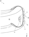
- FIG 1 a tyre (in partial perspective section) comprising a monitoring device 1 according to the present invention.
- the monitoring device 1 comprises a housing portion 2 and a base portion 3 mutually integral, the base portion 3 having a coupling surface 4 in single-piece intended for fixing the monitoring device to the tyre (exemplarily coinciding with a base face of the base portion facing the tyre), wherein a projection 5 (shown by dashed line in figure 3 ) of the housing portion 2 onto the coupling surface 4 has an extension lower than the coupling surface 4.
- the base portion 3 has circular perimetral edge and the housing portion 2 comprises a rigid body 7 having cylindrical shape, wherein the housing portion 2 is exemplarily arranged in central position of the base portion (and of the coupling surface 4).
- a axis 100 of the rigid body 7 passes through a centre (not shown) of the base portion 3.
- the projection 5 of the housing portion 2 coincides with a projection of the rigid body 7.
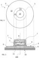
- the monitoring device 1 comprises an electronic unit 8, schematically shown in figure 2 , housed in the housing portion 2.
- the rigid body 7 is suitable for housing the electronic unit.
- the monitoring device 1 comprises an electric power supplier 11 (exemplarily a button battery) electrically connected to the electronic unit 8.
- an electric power supplier 11 exemplarily a button battery
- the monitoring device 1 comprises an encapsulation material 9 (e.g. a polyurethane material) which realizes with continuity at least part of the housing portion 2, enclosing the electric power supplier 11 and at least partially the electronic unit 8, and entirely the base portion 3 (and the coupling surface 4) to make the housing portion and the base portion mutually integral.
- the encapsulation material is poured in fluid form into the rigid body 7 to incorporate, after solidification, at least partially the electronic unit 8 and the electric power supplier 11 and to realize the base portion.
- the base portion 3 comprises a plurality of reinforcing elements (not shown) incorporated into the encapsulation material (at least at the base portion).
- the monitoring device exemplarily shown in figure 2 is of the type described in detail in the document WO2019/123118A1 in the name of the same Applicant.
- the monitoring device can be of the type described in the document WO2018/065846A1 in the name of the same Applicant.
- the base portion is made by a layer of elastomeric material (typically comprising a rubber reinforced with carbon black), and the housing portion and the base portion are distinct from each other and they are made mutually integral by gluing with structural adhesive (for example selected from the following: cyanoacrylate-based adhesive, polyurethane-based adhesive, epoxy adhesive, acrylic adhesive).
- the electronic unit 8 comprises at least one sensor (not shown) for sensing at least one of the following physical quantities: temperature, pressure, acceleration, deformation; a processing unit (not shown); a transceiver (not shown).
- a sensor for sensing at least one of the following physical quantities: temperature, pressure, acceleration, deformation
- a processing unit not shown
- a transceiver not shown
- the monitoring device 1 is fixed to an inner surface 15 of the tyre 10 at a crown portion 16 of the tyre 10 (i.e. the portion of tyre placed at the tread band 17) by an adhesive 6 interposed between the coupling surface 4 and the inner surface 15.
- first region 12 ( figures 2 and 3 ) of the coupling surface 4 is covered by the adhesive 6 and a second region 13 of the coupling surface 4, complementary to the first region 12, is free of adhesive 6.
- the second region 13 is contained within the projection 5 of the housing portion 2 onto the coupling surface 4.
- the second region 13 has circular shape concentric to the projection 5 of the housing portion 2, which is also circular.
- a projection of a centre of mass of the housing portion 2 onto the coupling surface 4 falls in a central position of the second region 13.
- the first region 12 and the second region 13 are continuous.
- the first region 12 has circular crown shape and completely surrounds the second region 13.
- Exemplarily the second region 13 has a plan extension equal to about 80% of the projection 5 of the housing portion 2.
- figure 3 shows the subdivision of the coupling surface respectively in the first and in the second region (solid line), together with the plan encumbrances of the projection of the housing portion (dashed line).
- dashed lines the extensions of the adhesive 6 and of the base portion 3 and of housing portion 2 of the monitoring device shown in figure 3 have been correlated by dashed lines to the surfaces of figure 3 .
- a distance D measured along the coupling surface 4 between an edge of the second region 13 and an ideal edge of the projection 5 of the housing portion 2 is equal to about 2.6 mm (exemplarily, given the cylindrical symmetry of the monitoring device 1, the distance D is a constant radial distance along an entire development of the edge of the second region).
- the adhesive 6 is a pressure sensitive adhesive (PSA), chosen from the following: acrylic adhesive, silicone adhesive, butyl adhesive, natural rubber-based adhesive or block copolymer-based adhesive.
- PSA pressure sensitive adhesive
- the adhesive 6 has a uniform thickness equal to about 80 ⁇ m (in figure 2 the thickness of the adhesive is shown not in scale for better clarity).
- monitoring devices of the type described in the document WO2019/123118A1 have been used, having a diameter of the base portion equal to 55 mm, a diameter of the housing portion (e.g. diameter of the rigid body 7) equal to 25 mm, and a surface extension of the second region equal to 80% of the projection of the housing portion.
- tyres used was front and rear tyres, produced by the same Applicant, suitable for sport vehicles.
- example C two spatially selective gluing according to the present invention having same surface extension of the second region, distinct from each other by the thickness of the adhesive applied to the coupling surface, were instead compared.
- the test performed was one of those of example A.
- the Applicant has performed an indoor high-speed thermomechanical cyclic fatigue test, based on the speed profiles of the certification tests GB/T (38°C ambient temperature - 1,7 m road wheel) and ECE (25°C ambient temperature - 2,0 m road wheel) for Y or (Y) tyres, which involves the rotation of the tyre under conditions that simulate the on-road application.
- the latter in particular, is simulated through a wheel (called “road wheel”) respectively having the aforementioned diameters, on which the tyre is placed with contact, the tyre being in turn subjected to a (constant) load.
- the test was hardened by continuing above 300 km/h, further increasing the speed by 10 km/h every 10 minutes until the failure of tyre and/or of the monitoring device.
- the gluing of the monitoring device according to the present invention allows to achieve higher speeds than the speeds achieved in presence of complete gluing of the monitoring device. It is also noted that for the tyres comprising the monitoring device with spatially selective gluing, the end of the test is due to the failure of the tyre and/or of the electronics (e.g. due to local overheating), but not to the detachment and/or to the breakage of the monitoring device (as instead occurs in cases of complete gluing).
- the gluing tightness of the monitoring device was evaluated by an indoor test of validation of the maximum homologation speed of the tyre according to GB/T (38°C ambient temperature - 1,7 m road wheel, first table) or ECE (25°C ambient temperature - 2,0 m road wheel, second table) standard, which involves (using an experimental apparatus similar to that described above) the ramp increase of the speed until reaching the maximum homologation linear speed of the given type of tyre (exemplarily equal to 350 km/h) and the maintenance of this homologation speed for a given time interval (also in this case the speeds are reported in terms of linear speeds).
- GB/T 38°C ambient temperature - 1,7 m road wheel, first table
- ECE 25°C ambient temperature - 2,0 m road wheel, second table
- the gluing method according to the present invention allows the tyre comprising the monitoring device to pass the test, while the breakage and/or the detachment of the monitoring device is observed in case of complete gluing of the latter.
- the gluing methodology according to the present invention has led to the pass of the test for all the used types of tyre.
- the Applicant has also tested the effects of the variation of the adhesive thickness in monitoring devices having spatially selective gluing with the same extension of the second region.
- the indoor test performed is the same as performed in example A with GB/T certification test.
- the use of a thinner adhesive thickness for a given surface covered by adhesive allows to further reduce the aforementioned adhesive accumulation phenomenon, which is believed to be the cause of the failure (e.g. detachment) of the monitoring device.
- Tyres comprising monitoring devices with spatially selective gluing with the two different thicknesses of adhesive (i.e. 80 ⁇ m and 120 ⁇ m) as tested in example C, have also been subjected by the Applicant to a fatigue test (i.e. a stress test of the tyre rolling in an overloaded condition with respect to the respective load index).
- the test result was positive for both the tyres.
- the tyre having an adhesive thickness equal to 120 ⁇ m lasted in the test for a time 25% greater than the time of the tyre having an adhesive thickness equal to 80 ⁇ m.
- the choice of adhesive thickness may therefore depend on the intended use of the tyre. For example, for a racing tyre (e.g. motorsport applications) in which the use at very high speeds is essentially privileged, it may be appropriate to choose reduced adhesive thicknesses (e.g. 80 ⁇ m), while for applications for longer road use, it may be convenient to choose greater adhesive thicknesses (e.g. 120 ⁇ m).
- reduced adhesive thicknesses e.g. 80 ⁇ m
- greater adhesive thicknesses e.g. 120 ⁇ m
Landscapes
- Engineering & Computer Science (AREA)
- Mechanical Engineering (AREA)
- Measuring Fluid Pressure (AREA)
- Tires In General (AREA)
Claims (11)
- Reifen (10), umfassend eine Überwachungsvorrichtung (1), wobei die Überwachungsvorrichtung (1) einen Gehäuseabschnitt (2) und einen Basisabschnitt (3) umfasst, die einstückig miteinander verbunden sind, wobei der Basisabschnitt (3) eine Kopplungsfläche (4) in einem Stück aufweist, die dazu bestimmt ist, die Überwachungsvorrichtung (1) an dem Reifen (10) zu befestigen, wobei ein Vorsprung (5) des Gehäuseabschnitts (2) auf die Kopplungsfläche (4) eine Erstreckung aufweist, die geringer als die Kopplungsfläche (4) ist,wobei die Überwachungsvorrichtung (1) eine elektronische Einheit (8) umfasst, die in dem Gehäuseabschnitt (2) untergebracht ist,wobei die Überwachungsvorrichtung (1) an einer Innenfläche (15) des Reifens (10) an einem Kronenabschnitt (16) des Reifens (10) durch einen Klebstoff (6) befestigt ist, der zwischen der Kopplungsfläche (4) und der Innenfläche (15) eingefügt ist,wobei ein erster Bereich (12) der Kopplungsfläche (4) durch den Klebstoff (6) bedeckt ist und ein zweiter Bereich (13) der Kopplungsfläche (4), komplementär zu dem ersten Bereich (12), frei von Klebstoff (6) ist, und wobei der zweite Bereich (13) in dem Vorsprung (5) des Gehäuseabschnitts (2) auf die Kopplungsfläche (4) enthalten ist, dadurch gekennzeichnet, dass der Klebstoff (6) eine Dicke von kleiner als oder gleich 200 µm aufweist.
- Reifen (10) nach Anspruch 1, wobei der erste Bereich (12) den zweiten Bereich (13) vollständig umgibt, wobei der erste Bereich (12) kontinuierlich ist und/oder der zweite Bereich (13) kontinuierlich ist, und wobei ein Vorsprung eines Massenschwerpunkts des Gehäuseabschnitts (2) auf die Kopplungsfläche (4) in eine zentrale Position des zweiten Bereichs (13) fällt.
- Reifen (10) nach einem der vorstehenden Ansprüche, wobei der Gehäuseabschnitt (2) in einer im Wesentlichen zentralen Position des Basisabschnitts (3) angeordnet ist, bevorzugt der Kopplungsfläche (4), und wobei der zweite Bereich (13) in einer im Wesentlichen zentralen Position des Vorsprungs (5) des Gehäuseabschnitts (2) angeordnet ist.
- Reifen (10) nach einem der vorstehenden Ansprüche, wobei der zweite Bereich (13) eine ebene Erstreckung von mehr als oder gleich 45 % und kleiner als oder gleich 95 % des Vorsprungs (5) des Gehäuseabschnitts (2) aufweist, wobei eine Form des zweiten Bereichs (13) mit einem Skalierungsfaktor eine Form des Vorsprungs (5) des Gehäuseabschnitts (2) reproduziert.
- Reifen (10) nach einem der vorstehenden Ansprüche, wobei ein Abstand (D), gemessen entlang der Kopplungsfläche (4) zwischen einem Rand des zweiten Bereichs (13) und einem idealen Rand des Vorsprungs (5) des Gehäuseabschnitts (2), mindestens gleich 1 mm, bevorzugt mindestens 2 mm, entlang einer gesamten Entwicklung des Rands des zweiten Bereichs (13) ist, und wobei der Abstand höchstens 5 mm beträgt.
- Reifen (10) nach einem der vorstehenden Ansprüche, wobei der Klebstoff (6) ein druckempfindlicher Klebstoff ist, der aus der folgenden Gruppe ausgewählt ist: Acrylklebstoff, Silikonklebstoff, Butylklebstoff, Klebstoff auf Naturkautschukbasis, Klebstoff auf Blockcopolymerbasis.
- Reifen (10) nach einem der vorstehenden Ansprüche, wobei der Klebstoff (6) eine Dicke von kleiner als oder gleich 150 µm aufweist und wobei die Dicke des Klebstoffs (6) einheitlich ist.
- Reifen (10) nach einem der vorstehenden Ansprüche, wobei der Gehäuseabschnitt (2) einen starren Körper (7) umfasst, der zum Unterbringen der elektronischen Einheit (8) geeignet ist, wobei der Vorsprung (5) des Gehäuseabschnitts (2) mit einem Vorsprung des starren Körpers (7) zusammenfällt, wobei die elektronische Einheit (8) mindestens einen Sensor zum Erfassen mindestens einer der folgenden physikalischen Größen umfasst: Temperatur, Druck, Beschleunigung, Verformung; eine Verarbeitungseinheit; einen Sendeempfänger, wobei die Überwachungsvorrichtung (1) einen elektrischen Stromversorger (11) umfasst, der elektrisch mit der elektronischen Einheit (8) verbunden ist, wobei der Basisabschnitt (3) einen Umfangsrand aufweist, der frei von Ecken, Spitzen und/oder Abschnitten mit kleinen Krümmungsradien ist, wobei der Gehäuseabschnitt (2), bevorzugt der starre Körper (7), im Wesentlichen eine zylindrische oder prismatische Form aufweist, wobei der Basisabschnitt (3) eine Vielzahl von Verstärkungselementen umfasst, die Textil- oder metallische Filamente oder Kordeln umfassen, wobei die Textilfilamente oder -kordeln aus einem oder mehreren der folgenden Textilmaterialien hergestellt sind: Aramid, Kunstseide, Polyester, Nylon, Lyocell, und wobei die Verstärkungselemente mit einer Dichte zwischen 30 Kordeln/dm und 500 Kordeln/dm angeordnet sind.
- Reifen (10) nach einem der vorstehenden Ansprüche, wobei der Basisabschnitt (3) einen kreisförmigen oder ovalen Umfangsrand aufweist oder
wobei der Basisabschnitt (3) einen Umfangsrand mit einem wellenförmigen Verlauf entlang einer im Wesentlichen kreisförmigen oder ovalen Mantellinie aufweist. - Reifen (10) nach einem der vorstehenden Ansprüche, wobei die Überwachungsvorrichtung (1) ein Einkapselungsmaterial (9) umfasst, das die elektronische Einheit (8) mindestens teilweise umschließt, wobei das Einkapselungsmaterial (9) mindestens einen Teil des Gehäuseabschnitts (2) und mindestens einen Teil des Basisabschnitts (3) mit Kontinuität ausbildet, um den Gehäuseabschnitt (2) und den Basisabschnitt (3) einstückig miteinander zu verbinden, wobei das Einkapselungsmaterial (9) ein Polyurethanmaterial oder ein Polyharnstoff ist, und wobei Verstärkungselemente dem Einkapselungsmaterial (9) zugeordnet oder in dieses eingearbeitet sind.
- Reifen (10) nach einem der Ansprüche 1 bis 9, wobei der Basisabschnitt (3) aus einer Schicht aus Elastomermaterial hergestellt ist, wobei der Gehäuseabschnitt (2) und der Basisabschnitt (3) sich voneinander unterscheiden und durch Verkleben mit Strukturklebstoff einstückig miteinander verbunden werden, wobei der Strukturklebstoff aus der folgenden Gruppe ausgewählt ist: Klebstoff auf Cyanacrylatbasis, Klebstoff auf Polyurethanbasis, Epoxidklebstoff, Acrylklebstoff.
Applications Claiming Priority (2)
| Application Number | Priority Date | Filing Date | Title |
|---|---|---|---|
| IT202000025513 | 2020-10-27 | ||
| PCT/IT2021/050336 WO2022091150A1 (en) | 2020-10-27 | 2021-10-18 | Tyre comprising a monitoring device |
Publications (3)
| Publication Number | Publication Date |
|---|---|
| EP4237262A1 EP4237262A1 (de) | 2023-09-06 |
| EP4237262C0 EP4237262C0 (de) | 2025-06-04 |
| EP4237262B1 true EP4237262B1 (de) | 2025-06-04 |
Family
ID=74592364
Family Applications (1)
| Application Number | Title | Priority Date | Filing Date |
|---|---|---|---|
| EP21806417.8A Active EP4237262B1 (de) | 2020-10-27 | 2021-10-18 | Reifen mit einer überwachungsvorrichtung |
Country Status (5)
| Country | Link |
|---|---|
| US (1) | US20230391148A1 (de) |
| EP (1) | EP4237262B1 (de) |
| CN (1) | CN116323164A (de) |
| BR (1) | BR112023005694A2 (de) |
| WO (1) | WO2022091150A1 (de) |
Families Citing this family (1)
| Publication number | Priority date | Publication date | Assignee | Title |
|---|---|---|---|---|
| EP4299298B1 (de) * | 2022-06-27 | 2025-11-05 | Bridgestone Europe NV/SA | Verfahren zum aufkleben einer vorrichtung auf einen reifen |
Family Cites Families (3)
| Publication number | Priority date | Publication date | Assignee | Title |
|---|---|---|---|---|
| DE102007030238B4 (de) * | 2007-06-29 | 2023-02-02 | Continental Reifen Deutschland Gmbh | Fahrzeugluftreifen mit einem Elektronikmodul |
| DE102007030232B4 (de) * | 2007-06-29 | 2018-12-13 | Continental Reifen Deutschland Gmbh | Reifenmodul für Fahrzeugreifen |
| MX2020007256A (es) * | 2017-12-18 | 2020-10-28 | Pirelli | Dispositivo de supervision de neumaticos que incluye una unidad electronica y el neumatico que contiene dicho dispositivo. |
-
2021
- 2021-10-18 WO PCT/IT2021/050336 patent/WO2022091150A1/en not_active Ceased
- 2021-10-18 US US18/248,960 patent/US20230391148A1/en active Pending
- 2021-10-18 CN CN202180069827.6A patent/CN116323164A/zh active Pending
- 2021-10-18 EP EP21806417.8A patent/EP4237262B1/de active Active
- 2021-10-18 BR BR112023005694A patent/BR112023005694A2/pt unknown
Also Published As
| Publication number | Publication date |
|---|---|
| WO2022091150A1 (en) | 2022-05-05 |
| US20230391148A1 (en) | 2023-12-07 |
| CN116323164A (zh) | 2023-06-23 |
| EP4237262C0 (de) | 2025-06-04 |
| BR112023005694A2 (pt) | 2023-04-25 |
| EP4237262A1 (de) | 2023-09-06 |
Similar Documents
| Publication | Publication Date | Title |
|---|---|---|
| RU2372209C2 (ru) | Структурно несущая шина, а также способ определения поперечного профиля перемычки-спицы для такой шины | |
| EP1420964B1 (de) | Nicht- pneumatischer reifen | |
| EP0502353B1 (de) | Druckloser Reifen für Reserverad | |
| US11780276B2 (en) | Tyre comprising monitoring device with a flexible support | |
| EP4237262B1 (de) | Reifen mit einer überwachungsvorrichtung | |
| EP0353006A2 (de) | Elastischer Reifen | |
| EP2845751B1 (de) | Struktur zur befestigung eines elektronischen bauteils an einer luftreifen-innenoberfläche | |
| EP2213478B1 (de) | Reifen- und felgenanordnung | |
| US20060113016A1 (en) | Non-pneumatic tire | |
| CN110861449B (zh) | 一种仿生非充气车轮 | |
| CN112469574B (zh) | 充气轮胎 | |
| JP7299745B2 (ja) | タイヤ | |
| EP1670652A1 (de) | Elastomerer reifen mit bogenförmigen schultern | |
| FR2953459A1 (fr) | Bourrelet de pneumatique pour vehicule lourd de type genie civil | |
| CN207790207U (zh) | 一种减震效果好的公路用轮胎 | |
| US11518198B2 (en) | Adapter for a rolling assembly and rolling assembly comprising same | |
| US20230001753A1 (en) | Tyre for motor-cycles comprising a monitoring device | |
| KR20030009212A (ko) | 개선된 타이어 카커스 고정 구조를 구비한 타이어 | |
| EP3632707A1 (de) | Reifen und reifenherstellungsverfahren | |
| RU2269425C2 (ru) | Непневматическая шина | |
| CN112847166B (zh) | 碳纤维砂轮及制作方法 | |
| CN2314961Y (zh) | 充丸耐扎轮胎 | |
| WO2021001862A1 (en) | Tyre comprising a monitoring device | |
| JP2022061221A (ja) | エアレスタイヤ及びエアレスタイヤの製造方法 |
Legal Events
| Date | Code | Title | Description |
|---|---|---|---|
| STAA | Information on the status of an ep patent application or granted ep patent |
Free format text: STATUS: UNKNOWN |
|
| STAA | Information on the status of an ep patent application or granted ep patent |
Free format text: STATUS: THE INTERNATIONAL PUBLICATION HAS BEEN MADE |
|
| PUAI | Public reference made under article 153(3) epc to a published international application that has entered the european phase |
Free format text: ORIGINAL CODE: 0009012 |
|
| STAA | Information on the status of an ep patent application or granted ep patent |
Free format text: STATUS: REQUEST FOR EXAMINATION WAS MADE |
|
| 17P | Request for examination filed |
Effective date: 20230329 |
|
| AK | Designated contracting states |
Kind code of ref document: A1 Designated state(s): AL AT BE BG CH CY CZ DE DK EE ES FI FR GB GR HR HU IE IS IT LI LT LU LV MC MK MT NL NO PL PT RO RS SE SI SK SM TR |
|
| DAV | Request for validation of the european patent (deleted) | ||
| DAX | Request for extension of the european patent (deleted) | ||
| GRAP | Despatch of communication of intention to grant a patent |
Free format text: ORIGINAL CODE: EPIDOSNIGR1 |
|
| STAA | Information on the status of an ep patent application or granted ep patent |
Free format text: STATUS: GRANT OF PATENT IS INTENDED |
|
| INTG | Intention to grant announced |
Effective date: 20250203 |
|
| GRAS | Grant fee paid |
Free format text: ORIGINAL CODE: EPIDOSNIGR3 |
|
| GRAA | (expected) grant |
Free format text: ORIGINAL CODE: 0009210 |
|
| STAA | Information on the status of an ep patent application or granted ep patent |
Free format text: STATUS: THE PATENT HAS BEEN GRANTED |
|
| AK | Designated contracting states |
Kind code of ref document: B1 Designated state(s): AL AT BE BG CH CY CZ DE DK EE ES FI FR GB GR HR HU IE IS IT LI LT LU LV MC MK MT NL NO PL PT RO RS SE SI SK SM TR |
|
| REG | Reference to a national code |
Ref country code: GB Ref legal event code: FG4D |
|
| REG | Reference to a national code |
Ref country code: CH Ref legal event code: EP |
|
| REG | Reference to a national code |
Ref country code: DE Ref legal event code: R096 Ref document number: 602021031892 Country of ref document: DE |
|
| REG | Reference to a national code |
Ref country code: IE Ref legal event code: FG4D |
|
| U01 | Request for unitary effect filed |
Effective date: 20250612 |
|
| U07 | Unitary effect registered |
Designated state(s): AT BE BG DE DK EE FI FR IT LT LU LV MT NL PT RO SE SI Effective date: 20250624 |
|
| PG25 | Lapsed in a contracting state [announced via postgrant information from national office to epo] |
Ref country code: ES Free format text: LAPSE BECAUSE OF FAILURE TO SUBMIT A TRANSLATION OF THE DESCRIPTION OR TO PAY THE FEE WITHIN THE PRESCRIBED TIME-LIMIT Effective date: 20250604 |
|
| PG25 | Lapsed in a contracting state [announced via postgrant information from national office to epo] |
Ref country code: NO Free format text: LAPSE BECAUSE OF FAILURE TO SUBMIT A TRANSLATION OF THE DESCRIPTION OR TO PAY THE FEE WITHIN THE PRESCRIBED TIME-LIMIT Effective date: 20250904 Ref country code: GR Free format text: LAPSE BECAUSE OF FAILURE TO SUBMIT A TRANSLATION OF THE DESCRIPTION OR TO PAY THE FEE WITHIN THE PRESCRIBED TIME-LIMIT Effective date: 20250905 |
|
| PG25 | Lapsed in a contracting state [announced via postgrant information from national office to epo] |
Ref country code: PL Free format text: LAPSE BECAUSE OF FAILURE TO SUBMIT A TRANSLATION OF THE DESCRIPTION OR TO PAY THE FEE WITHIN THE PRESCRIBED TIME-LIMIT Effective date: 20250604 |
|
| PG25 | Lapsed in a contracting state [announced via postgrant information from national office to epo] |
Ref country code: HR Free format text: LAPSE BECAUSE OF FAILURE TO SUBMIT A TRANSLATION OF THE DESCRIPTION OR TO PAY THE FEE WITHIN THE PRESCRIBED TIME-LIMIT Effective date: 20250604 |
|
| PG25 | Lapsed in a contracting state [announced via postgrant information from national office to epo] |
Ref country code: RS Free format text: LAPSE BECAUSE OF FAILURE TO SUBMIT A TRANSLATION OF THE DESCRIPTION OR TO PAY THE FEE WITHIN THE PRESCRIBED TIME-LIMIT Effective date: 20250904 |
|
| U20 | Renewal fee for the european patent with unitary effect paid |
Year of fee payment: 5 Effective date: 20251027 |