EP4236221A1 - Vorrichtung und verfahren zur papr-unterdrückung mit adaptivem spitzen-zu-durchschnitts-verhältnis und kommunikationsvorrichtung - Google Patents
Vorrichtung und verfahren zur papr-unterdrückung mit adaptivem spitzen-zu-durchschnitts-verhältnis und kommunikationsvorrichtung Download PDFInfo
- Publication number
- EP4236221A1 EP4236221A1 EP20963065.6A EP20963065A EP4236221A1 EP 4236221 A1 EP4236221 A1 EP 4236221A1 EP 20963065 A EP20963065 A EP 20963065A EP 4236221 A1 EP4236221 A1 EP 4236221A1
- Authority
- EP
- European Patent Office
- Prior art keywords
- clipping
- carrier
- input signal
- parameter
- inter
- Prior art date
- Legal status (The legal status is an assumption and is not a legal conclusion. Google has not performed a legal analysis and makes no representation as to the accuracy of the status listed.)
- Pending
Links
Images



Classifications
-
- H—ELECTRICITY
- H04—ELECTRIC COMMUNICATION TECHNIQUE
- H04L—TRANSMISSION OF DIGITAL INFORMATION, e.g. TELEGRAPHIC COMMUNICATION
- H04L27/00—Modulated-carrier systems
- H04L27/26—Systems using multi-frequency codes
- H04L27/2601—Multicarrier modulation systems
- H04L27/2614—Peak power aspects
- H04L27/2623—Reduction thereof by clipping
-
- H—ELECTRICITY
- H04—ELECTRIC COMMUNICATION TECHNIQUE
- H04L—TRANSMISSION OF DIGITAL INFORMATION, e.g. TELEGRAPHIC COMMUNICATION
- H04L5/00—Arrangements affording multiple use of the transmission path
- H04L5/0001—Arrangements for dividing the transmission path
- H04L5/0003—Two-dimensional division
- H04L5/0005—Time-frequency
- H04L5/0007—Time-frequency the frequencies being orthogonal, e.g. OFDM(A) or DMT
- H04L5/001—Time-frequency the frequencies being orthogonal, e.g. OFDM(A) or DMT the frequencies being arranged in component carriers
Definitions
- This application relates to the field of communication technologies, and in particular, to an adaptive peak to average power ratio PAPR suppression apparatus and method, and a communication device.
- OFDM Orthogonal Frequency Division Multiplexing, orthogonal frequency division multiplexing
- OFDM Orthogonal Frequency Division Multiplexing, orthogonal frequency division multiplexing
- a clipping algorithm is designed on an intermediate frequency side of a transmitter, to reduce a PAPR, protect a power amplifier, and improve power amplifier efficiency.
- PAPR suppression apparatus and method and a communication device are provided.
- PAPR suppression is performed based on collaboration between two clipping modules, so that an implementation is simple and is applicable to a plurality of scenarios, and it is ensured that no clipping is missed, a PAPR is controllable, and a power amplifier is protected.
- an embodiment of this application provides an adaptive peak to average power ratio PAPR suppression apparatus.
- the apparatus includes a first clipping module and a second clipping module.
- the second clipping module outputs, to the first clipping module, a to-be-clipped signal that satisfies an input condition of the first clipping module, where the input condition includes a peak distribution feature of an input signal.
- the first clipping module performs first clipping processing on the to-be-clipped signal, to obtain a first clipped signal.
- PAPR suppression is performed based on collaboration between the two clipping modules.
- the foregoing implementation of this application is applicable to a plurality of scenarios. It is ensured that no clipping is missed, a PAPR is controllable, and a power amplifier is protected.
- this manner of pre-configuring a clipping parameter based on a statistical feature in this application is simpler. This resolves a technical problem that a static clipping algorithm is excessively complex or an application scenario is limited in the related technology.
- the second clipping module is configured to obtain an input signal, and when a carrier parameter of the input signal does not satisfy the input condition of the first clipping module, perform second clipping processing on the input signal based on the carrier parameter of the input signal and the input condition, to obtain the to-be-clipped signal.
- the second clipping module is configured to obtain the input signal, and when the carrier parameter of the input signal satisfies the input condition of the first clipping module, output the input signal, which is used as the to-be-clipped signal, to the first clipping module.
- the second clipping module in a bypass mode, is further configured to obtain an input signal, and output the input signal to the first clipping module.
- the first clipping module is configured to perform third clipping processing on the input signal based on a clipping parameter corresponding to a carrier parameter of the input signal.
- the clipping parameter is configured for different carriers based on a statistical feature of peak distribution of the input signal.
- the carrier parameter is an inter-carrier power ratio
- the clipping parameter is a weighting coefficient of clipping noise
- adaptive weighted allocation on the clipping noise by the first clipping module is implemented in a manner of configuring different clipping parameters for different carrier configurations based on the statistical feature of the peak distribution of the input signal.
- the foregoing implementation of this application is applicable to a plurality of scenarios. It is ensured that no clipping is missed, the PAPR is controllable, and the power amplifier is protected. In comparison with the manner in which each peak value needs to be extracted for clipping processing in the strict scenario, this manner of pre-configuring the clipping parameter based on the statistical feature in this application is simpler.
- the input condition of the first clipping module is a static first inter-carrier statistical feature.
- the second clipping module is configured to: when the carrier parameter of the input signal does not satisfy the first inter-carrier statistical feature, perform second clipping processing on the input signal based on the carrier parameter of the input signal and the first inter-carrier statistical feature, to obtain the to-be-clipped signal.
- the first clipping module is configured to perform first clipping processing on the to-be-clipped signal based on a clipping parameter corresponding to the first inter-carrier statistical feature, to obtain the first clipped signal.
- PAPR control of a signal in any scenario is applicable, and an implementation is simple.
- the input condition of the first clipping module is a dynamic second inter-carrier statistical feature
- the first clipping module is configured to periodically update the second carrier statistical feature and a clipping parameter corresponding to the second carrier statistical feature.
- the second clipping module is configured to: when the carrier parameter of the input signal does not satisfy the second inter-carrier statistical feature, perform second clipping processing on the input signal based on the carrier parameter of the input signal and the second inter-carrier statistical feature, to obtain the to-be-clipped signal.
- the first clipping module is configured to perform first clipping processing on the to-be-clipped signal based on the clipping parameter corresponding to the second inter-carrier statistical feature, to obtain the first clipped signal.
- the first clipping module periodically collects statistics of an inter-carrier feature of the input signal, and updates, based on the inter-carrier feature obtained through statistics collection, the second inter-carrier statistical feature and the corresponding clipping parameter that are locally configured, so that adaptive clipping processing can also be implemented.
- PAPR control of a signal in any scenario is applicable, and an implementation is simple.
- the carrier parameter of the input signal, the first inter-carrier statistical feature, and the second carrier statistical feature each include an inter-carrier power ratio.
- an embodiment of this application provides a communication device, including the adaptive peak to average power ratio PAPR suppression apparatus in any implementation of the first aspect.
- an embodiment of this application provides a communication system.
- the communication system includes a baseband unit BBU, and the communication system further includes a radio remote unit RRU or an active antenna unit AAU.
- the first clipping module in any implementation of the first aspect is in the RRU or the AAU
- the second clipping module in any implementation of the first aspect is in the BBU.
- both the first clipping module and the second clipping module in any implementation of the first aspect are in the RRU or the AAU.
- an embodiment of this application provides an adaptive peak to average power ratio PAPR suppression method, where the method is applied to a communication device.
- the method includes the following steps.
- the communication device performs second clipping processing on an input signal whose carrier parameter does not satisfy an input condition, to obtain a to-be-clipped signal, and performs first clipping processing on the to-be-clipped signal, to obtain a first clipped signal.
- the input condition includes a peak distribution feature of an input signal, and a carrier parameter of the to-be-clipped signal satisfies the input condition.
- preprocessing (second clipping processing) is performed on the input signal that does not satisfy the peak distribution feature, to obtain the to-be-clipped signal that satisfies the peak distribution feature, and then first clipping processing is performed on the to-be-clipped signal, to obtain the first clipped signal.
- second clipping processing is performed on the input signal that does not satisfy the peak distribution feature, to obtain the to-be-clipped signal that satisfies the peak distribution feature
- first clipping processing is performed on the to-be-clipped signal, to obtain the first clipped signal.
- this manner of pre-configuring a clipping parameter based on a statistical feature and preprocessing the input signal in this application is simpler. This resolves a technical problem that a static clipping algorithm is excessively complex or an application scenario is limited in the related technology.
- that the communication device performs second clipping processing on an input signal whose carrier parameter does not satisfy an input condition, to obtain a to-be-clipped signal includes:
- the communication device performs second clipping processing on the input signal based on the carrier parameter of the input signal and the input condition when the carrier parameter of the input signal does not satisfy the input condition, to obtain the to-be-clipped signal.
- the method further includes: The communication device performs first clipping processing on an input signal whose carrier parameter satisfies the input condition, to obtain the first clipped signal.
- the PAPR suppression method in the foregoing implementation of this application different clipping processes are used for the input signal based on a relationship between the carrier parameter of the input signal and the input condition.
- the foregoing implementation of this application is applicable to a plurality of scenarios. It is ensured that no clipping is missed, a PAPR is controllable, and a power amplifier is protected.
- this manner of pre-configuring a clipping parameter based on a statistical feature and preprocessing the input signal in this application is simpler. This resolves a technical problem that a static clipping algorithm is excessively complex or an application scenario is limited in the related technology.
- the method further includes:
- the communication device performs third clipping processing on the input signal based on a clipping parameter corresponding to the carrier parameter of the input signal.
- the clipping parameter is configured for different carriers based on a statistical feature of peak distribution of the input signal.
- the carrier parameter is an inter-carrier power ratio
- the clipping parameter is a weighting coefficient of clipping noise
- adaptive weighted allocation on the clipping noise is implemented by the communication device in a manner of configuring different clipping parameters for different carrier configurations based on the statistical feature of the peak distribution of the input signal.
- the foregoing implementation of this application is applicable to a plurality of scenarios. It is ensured that no clipping is missed, the PAPR is controllable, and the power amplifier is protected. In comparison with the manner in which each peak value needs to be extracted for clipping processing in the strict scenario, this manner of pre-configuring the clipping parameter based on the statistical feature in this application is simpler.
- the input condition is a static first inter-carrier statistical feature.
- That the communication device performs second clipping processing on the input signal based on the carrier parameter of the input signal and the input condition when the carrier parameter of the input signal does not satisfy the input condition, to obtain the to-be-clipped signal includes:
- the communication device When the carrier parameter of the input signal does not satisfy the first inter-carrier statistical feature, the communication device performs second clipping processing on the input signal based on the carrier parameter of the input signal and the first inter-carrier statistical feature, to obtain the to-be-clipped signal.
- That the communication device performs first clipping processing on the to-be-clipped signal, to obtain a first clipped signal includes:
- the communication device performs first clipping processing on the to-be-clipped signal based on a clipping parameter corresponding to the first inter-carrier statistical feature, to obtain the first clipped signal.
- the method further includes:
- the communication device configures, based on the first inter-carrier statistical feature, the clipping parameter corresponding to the first inter-carrier statistical feature.
- PAPR suppression method in the foregoing implementation of this application, according to a process in which clipping processing is adaptively enabled based on a relationship between the input signal and the first inter-carrier statistical feature and clipping processing is performed on the input signal, PAPR control of a signal in any scenario is applicable, and an implementation is simple.
- the input condition is a dynamic second carrier statistical feature.
- the method further includes:
- the communication device periodically obtains a new second carrier statistical feature, and configures, based on the new second carrier statistical feature, a clipping parameter corresponding to the new second carrier statistical feature.
- the communication device performs second clipping processing on the input signal based on the carrier parameter of the input signal and the input condition when the carrier parameter of the input signal does not satisfy the input condition, to obtain the to-be-clipped signal includes:
- the communication device When the carrier parameter of the input signal does not satisfy the second inter-carrier statistical feature, the communication device performs second clipping processing on the input signal based on the carrier parameter of the input signal and the second inter-carrier statistical feature, to obtain the to-be-clipped signal.
- That the communication device performs first clipping processing on the to-be-clipped signal, to obtain a first clipped signal includes:
- the communication device performs first clipping processing on the to-be-clipped signal based on a clipping parameter corresponding to the second inter-carrier statistical feature, to obtain the first clipped signal.
- the carrier parameter of the input signal, the first inter-carrier statistical feature, and the second carrier statistical feature each are an inter-carrier power ratio.
- an embodiment of this application provides an adaptive peak to average power ratio PAPR suppression apparatus.
- the apparatus is used in a communication device, and the apparatus includes: a clipping unit, configured to perform second clipping processing on an input signal whose carrier parameter does not satisfy an input condition, to obtain a to-be-clipped signal, and perform first clipping processing on the to-be-clipped signal, to obtain a first clipped signal, where the input condition includes a peak distribution feature of an input signal, and a carrier parameter of the to-be-clipped signal satisfies the input condition.
- the PAPR suppression apparatus in this application performs preprocessing (second clipping processing) on the input signal that does not satisfy the peak distribution feature, to obtain the to-be-clipped signal that satisfies the peak distribution feature, and then performs first clipping processing on the to-be-clipped signal, to obtain the first clipped signal.
- preprocessing second clipping processing
- first clipping processing on the to-be-clipped signal, to obtain the first clipped signal.
- this manner of pre-configuring a clipping parameter based on a statistical feature and preprocessing the input signal in this application is simpler. This resolves a technical problem that a static clipping algorithm is excessively complex or an application scenario is limited in the related technology.
- the clipping unit includes: a second clipping module, configured to: perform second clipping processing on the input signal based on the carrier parameter of the input signal and the input condition when the carrier parameter of the input signal does not satisfy the input condition, to obtain the to-be-clipped signal.
- the apparatus further includes: a first clipping module, configured to perform first clipping processing on an input signal whose carrier parameter satisfies the input condition, to obtain the first clipped signal.
- the apparatus further includes: a third clipping module, configured to perform third clipping processing on the input signal based on a clipping parameter corresponding to the carrier parameter of the input signal, where the clipping parameter is configured for different carriers based on a statistical feature of peak distribution of the input signal.
- a third clipping module configured to perform third clipping processing on the input signal based on a clipping parameter corresponding to the carrier parameter of the input signal, where the clipping parameter is configured for different carriers based on a statistical feature of peak distribution of the input signal.
- the carrier parameter is an inter-carrier power ratio
- the clipping parameter is a weighting coefficient of clipping noise
- adaptive weighted allocation on the clipping noise is implemented by the communication device in a manner of configuring different clipping parameters for different carrier configurations based on the statistical feature of the peak distribution of the input signal.
- the foregoing implementation of this application is applicable to a plurality of scenarios. It is ensured that no clipping is missed, the PAPR is controllable, and the power amplifier is protected. In comparison with the manner in which each peak value needs to be extracted for clipping processing in the strict scenario, this manner of pre-configuring the clipping parameter based on the statistical feature in this application is simpler.
- the input condition is a static first inter-carrier statistical feature.
- the second clipping module is further configured to: when the carrier parameter of the input signal does not satisfy the first inter-carrier statistical feature, perform second clipping processing on the input signal based on the carrier parameter of the input signal and the first inter-carrier statistical feature, to obtain the to-be-clipped signal.
- the first clipping module is further configured to perform first clipping processing on the to-be-clipped signal based on a clipping parameter corresponding to the first inter-carrier statistical feature, to obtain the first clipped signal.
- the apparatus further includes: a first configuration module, configured to configure, based on the first inter-carrier statistical feature, the clipping parameter corresponding to the first inter-carrier statistical feature.
- PAPR control of a signal in any scenario is applicable, and an implementation is simple.
- the input condition is a dynamic second carrier statistical feature.
- the apparatus further includes: a second configuration module, configured to periodically obtain a new second carrier statistical feature, and configure, based on the new second carrier statistical feature, a clipping parameter corresponding to the new second carrier statistical feature.
- the second clipping module is further configured to: when the carrier parameter of the input signal does not satisfy the second inter-carrier statistical feature, perform second clipping processing on the input signal based on the carrier parameter of the input signal and the second inter-carrier statistical feature, to obtain the to-be-clipped signal.
- the first clipping module is further configured to perform first clipping processing on the to-be-clipped signal based on a clipping parameter corresponding to the second inter-carrier statistical feature, to obtain the first clipped signal.
- the carrier parameter of the input signal, the first inter-carrier statistical feature, and the second carrier statistical feature each are an inter-carrier power ratio.
- an embodiment of this application provides an adaptive peak to average power ratio PAPR suppression apparatus, including: a processor; and a memory configured to store executable instructions of the processor, where the processor is configured to implement the method in any one of the fourth aspect or the implementations of the fourth aspect when executing the instructions.
- an embodiment of this application provides a non-volatile computer-readable storage medium, storing computer program instructions.
- the computer program instructions are executed by a processor, the method in any one of the fourth aspect or the implementations of the fourth aspect is implemented.
- an embodiment of this application provides a terminal device.
- the terminal device can perform the PAPR suppression method in one or more of the fourth aspect or the plurality of possible implementations of the fourth aspect.
- an embodiment of this application provides a computer program product, including computer-readable code or a non-volatile computer-readable storage medium carrying computer-readable code.
- a processor in the electronic device performs the PAPR suppression method in one or more of the fourth aspect or the plurality of possible implementations of the fourth aspect.
- example herein means “used as an example, embodiment or illustration”. Any embodiment described as “example” is not necessarily explained as being superior or better than other embodiments.
- Clipping Suppressing a peak value that exceeds a threshold that is set for a signal with a large peak value.
- a peak clipping process is referred to as clipping.
- Clipping noise A difference between an original signal and a clipping threshold.
- Carrier parameter A feature parameter of a carrier of a signal, for example, a modulation scheme of the carrier, a spectrum occupation status, a power spectral density, or inter-carrier instantaneous information, where the inter-carrier instantaneous information may include an inter-carrier power ratio, or the like.
- the modulation scheme of the carrier may be different for a phase, an amplitude, and the like of data carried on the carrier.
- the spectrum occupation status of the carrier may be a width of a spectrum occupied by the carrier, a location of the carrier in a frequency band, or the like.
- the inter-carrier instantaneous information may be information about a relationship between parameters between carriers at a moment.
- the inter-carrier power ratio may be a ratio of power configurations between different carriers.
- Inter-carrier statistical feature A result obtained by collecting statistics of a relationship between parameters between carriers of an input signal in a specific time period.
- an intermediate frequency clipping algorithm is designed based on a most strict scenario, implementation overheads are large and complexity is high. If an intermediate frequency clipping algorithm is designed based on a typical scenario, although implementation complexity is reduced, adaptability of the intermediate frequency clipping algorithm is poor, and clipping is missed when a signal peak feature changes, affecting robustness of a power amplifier.
- FIG. la and FIG. 1b each show an example of a clipping scenario in a related technology.
- FIG. 1a for example, in a strict scenario, a power characteristic of an input signal is enabled, and consequently peak distribution of the input signal becomes very dense. In this case, clipping is performed based on the most strict scenario, and clipping processing needs to be performed on each extracted peak value. As a result, implementation complexity is high, and overheads are large.
- FIG. 1b in a typical scenario, a power characteristic of an input signal is not enabled, a peak distribution feature of the input signal does not change (or changes slightly), and peak distribution of the input signal is sparse. In this case, clipping processing is performed based on a design of the typical scenario. However, a clipping processing method is applicable to a limited scenario, and clipping of a part of peak values may be missed when the clipping processing method is applied to a complex scenario.
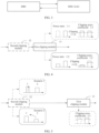
- FIG. 2 is a block diagram of a PAPR suppression apparatus according to an embodiment of this application.
- FIG. 3 is a schematic diagram of an application scenario according to an embodiment of this application.
- a communication device may include a BBU (Baseband Unit, baseband unit), an RRU (Radio Remote Unit, radio remote unit), and/or an AAU (Active Antenna Unit, active antenna unit).
- BBU Baseband Unit, baseband unit
- RRU Radio Remote Unit, radio remote unit
- AAU Active Antenna Unit, active antenna unit.
- the RRU may be mounted on a wall of an equipment room, the BBU is installed in a standard cabinet, and the RRU is connected to an antenna through a feeder Alternatively, the RRU is installed on a tower, the BBU is connected to the RRU through an optical fiber, and the RRU is connected to an antenna through a jumper.
- 4G fourth generation, fourth generation mobile communication technology
- a conventional integrated macro base station is completely replaced with a BBU+RRU+antenna mode, and some BBUs are centrally disposed in an equipment room to form a BBU pool.
- a massive MIMO (multiple-input multiple-output, multiple-input multiple-output) technology is introduced into 5G (Fifth Generation, fifth generation mobile communication technology), and therefore an AAU emerges.
- a PAPR suppression apparatus in an implementation provided in this application may include a first clipping module 11 and a second clipping module 12 shown in FIG. 2 .
- an input end of the second clipping module 12 is configured to receive an input signal
- an output end of the second clipping module 12 is connected to an input end of the first clipping module 11, and an output end of the first clipping module 11 outputs a clipped signal.
- an input condition includes a peak distribution feature of an input signal.
- the peak distribution feature of the input signal may include a statistical feature of peak distribution of the input signal.
- the peak distribution feature of the input signal is mainly affected by factors such as an inter-carrier power ratio of the input signal, a modulation scheme of a carrier, and a spectrum occupation status.
- the inter-carrier power ratio may be a ratio of power configurations between different carriers.
- the modulation scheme of the carrier may be different for a phase, an amplitude, and the like of data carried on the carrier.
- the spectrum occupation status of the carrier may be a width of a spectrum occupied by the carrier, a location of the carrier in a frequency band, or the like.
- the first clipping module 11 may include a clipping parameter configured based on the statistical feature of the peak distribution of the input signal.
- the first clipping module 11 may directly perform first clipping processing on the input signal based on the carrier parameter of the input signal and the clipping parameter.
- the clipping parameter may be data related to an allocation manner of clipping noise, for example, a ratio used for allocating clipping noise when different carriers are clipped, or a weighting coefficient of clipping noise corresponding to different carriers when different carriers are clipped.
- the inter-carrier power ratio of the input signal is 1:1. It is configured in the first clipping module 11 that, when the inter-carrier power ratio of the input signal is 1:1, a noise allocation ratio during clipping is also 1:1. When it is determined, based on the carrier parameter of the input signal, that the inter-carrier power ratio of the input signal is 1:1, the first clipping module 11 may perform first clipping processing on the input signal based on the configured clipping parameter (namely, the noise allocation ratio 1:1 during clipping).
- the second clipping module 12 may output, to the first clipping module 11, a to-be-clipped signal that satisfies the input condition of the first clipping module 11, and the first clipping module may perform first clipping processing on the to-be-clipped signal, to obtain a first clipped signal.
- the second clipping module 12 is configured to determine, depending on whether the carrier parameter of the input signal satisfies the input condition of the first clipping module 11, whether to enable second clipping processing on the input signal.
- the second clipping module 12 is configured to obtain the input signal, and when the carrier parameter of the input signal satisfies the input condition of the first clipping module 11, output the input signal, which is used as the to-be-clipped signal, to the first clipping module 11.
- the second clipping module 12 may skip enabling second clipping processing on the input signal, in other words, disable second clipping processing on the input signal.
- the second clipping module 12 may skip performing second clipping processing on the input signal.
- the second clipping module 12 is configured to obtain an input signal, and when a carrier parameter of the input signal does not satisfy the input condition of the first clipping module 11, perform second clipping processing on the input signal based on the carrier parameter of the input signal and the input condition, to obtain the to-be-clipped signal.
- the second clipping module 12 may determine to enable second clipping processing on the input signal.
- second clipping processing may be performed on the input signal, and a carrier parameter of the to-be-clipped signal obtained through second clipping processing satisfies the input condition of the first clipping module 11.
- the second clipping module 12 may be configured to perform preprocessing (second clipping processing) on the input signal, where the carrier parameter of the to-be-clipped signal obtained through preprocessing satisfies the input condition of the first clipping module 11, so that the first clipping module 11 may perform first clipping processing on the to-be-clipped signal, to obtain the first clipped signal.
- preprocessing second clipping processing
- the first clipping module 11 may be in an RRU or an AAU on an intermediate frequency side
- the second clipping module 12 may be in a BBU on a baseband side, or may be in the RRU or the AAU on the intermediate frequency side.
- Intermediate frequency clipping processing on the input signal is implemented based on collaboration between the first clipping module 11 and the second clipping module 12.
- PAPR suppression is performed based on collaboration between the two clipping modules.
- the foregoing implementation of this application is applicable to a plurality of scenarios. It is ensured that no clipping is missed, a PAPR is controllable, and a power amplifier is protected.
- this manner of pre-configuring a clipping parameter based on a statistical feature in this application is simpler. This resolves a technical problem that a static clipping algorithm is excessively complex or an application scenario is limited in the related technology.
- the second clipping module 12 in a bypass mode, is further configured to obtain an input signal, and output the input signal to the first clipping module 11.
- the first clipping module 11 is configured to perform third clipping processing on the input signal based on a clipping parameter corresponding to a carrier parameter of the input signal.
- the clipping parameter is configured for different carriers based on a statistical feature of peak distribution of the input signal.
- the second clipping module 12 may not be deployed.
- the first clipping module 11 directly obtains the input signal, and performs third clipping processing on the input signal based on the clipping parameter corresponding to the carrier parameter of the input signal.
- the carrier parameter may be an inter-carrier power ratio
- the clipping parameter may be a weighting coefficient of clipping noise.
- the first clipping module 11 is configured to determine the weighting coefficient of the clipping noise based on the clipping parameter corresponding to inter-carrier power ratio.
- the clipping parameter is configured for different carriers based on the statistical feature of the peak distribution of the input signal.
- the first clipping module may adaptively adjust the weighting coefficient of the clipping noise based on the inter-carrier power ratio of the input signal, and perform third clipping processing on the input signal based on the weighting coefficient of the clipping noise.
- adaptive weighted allocation on the clipping noise by the first clipping module 11 is implemented in a manner of configuring different clipping parameters for different carrier configurations based on the statistical feature of the peak distribution of the input signal.
- the foregoing implementation of this application is applicable to a plurality of scenarios. It is ensured that no clipping is missed, the PAPR is controllable, and the power amplifier is protected. In comparison with the manner in which each peak value needs to be extracted for clipping processing in the strict scenario, this manner of pre-configuring the clipping parameter based on the statistical feature in this application is simpler.
- the clipping noise may be adaptively allocated based on the inter-carrier power ratio, so that the clipping noise is better allocated, to ensure system performance.
- the second clipping module 12 is in the bypass mode, and the first clipping module 11 performs adaptive clipping.
- FIG. 4 is a block diagram of a PAPR suppression apparatus according to an embodiment of this application.
- a general input condition of the first clipping module 11 may be set, so that all input signals can satisfy the input condition.
- the second clipping module 12 may work in a bypass mode, and perform no processing on the input signal. After obtaining the input signal, the second clipping module 12 may directly output the input signal to an input end of the first clipping module 11.
- the second clipping module 12 is represented by a dashed box, and works in the bypass mode.
- the second clipping module 12 may not be deployed, and only the first clipping module 11 is deployed.
- the first clipping module 11 may directly obtain the input signal, and perform third clipping processing on the input signal based on a clipping parameter corresponding to a carrier parameter of the input signal.
- the corresponding clipping parameter may be configured in the first clipping module 11 based on a statistical feature that is of peak distribution of the input signal and that is obtained through statistics collection.
- the statistical feature of the peak distribution may be a feature of a carrier, for example, an inter-carrier power configuration, a modulation scheme of the carrier, or a spectrum occupation status of the carrier.
- different clipping parameters may be configured for different carriers based on the statistical feature of the peak distribution of the input signal.
- the first clipping module 11 may adaptively perform third clipping processing on the input signal based on the carrier parameter of the input signal and the clipping parameter that is configured based on the statistical feature of the carrier.
- different carriers of the input signal and clipping parameters corresponding to the different carriers may be recorded in a form of a table.
- the first clipping module 11 may obtain the corresponding clipping parameter by querying the table based on the carrier parameter of the input signal.
- an inter-carrier power ratio is used as an example.
- inter-carrier power ratios include 1:2 and 1:1 based on statistics
- clipping parameters respectively corresponding to 1:2 and 1:1 may be configured in the first clipping module 11.
- a corresponding weighting coefficient of clipping noise is 1:2 when the inter-carrier power ratio is 1:2
- a corresponding weighting coefficient of clipping noise is 1:1 when the inter-carrier power ratio is 1:1.
- the first clipping module 11 may perform third clipping processing on the input signal by using the weighting coefficient 1:2 of the clipping noise, in other words, an allocation ratio of the clipping noise between carriers during clipping is 1:2.
- the inter-carrier power ratio is 1:2
- an input signal with a low power corresponds to weak clipping noise (1)
- an input signal with a high power corresponds to strong clipping noise (2).
- the first clipping module 11 may perform third clipping processing on the input signal by using the weighting coefficient 1:1 of the clipping noise, in other words, the allocation ratio of the clipping noise between the carriers during clipping is 1:1.
- the clipping noise between the carriers is also in a 1:1 relationship during clipping, that is, the clipping noise allocated to the two carriers is the same.
- the first clipping module 11 shown in FIG. 4 is merely some examples of this application, and does not limit this application in any manner.
- the corresponding clipping parameter may alternatively be set based on another inter-carrier power ratio (for example, 1:5 or 1:10).
- the corresponding clipping parameter may alternatively be configured based on a statistical feature of other instantaneous information between the carriers.
- the corresponding clipping parameter may be configured based on a statistical feature of instantaneous information such as an inter-carrier modulation scheme or a spectrum occupation status.
- adaptive weighted allocation on the clipping noise by the first clipping module 11 is implemented in a manner of configuring different clipping parameters for different carrier configurations based on the statistical feature of the peak distribution of the input signal.
- the foregoing implementation of this application is applicable to a plurality of scenarios. It is ensured that no clipping is missed, the PAPR is controllable, and the power amplifier is protected. In comparison with the manner in which each peak value needs to be extracted for clipping processing in the strict scenario, this manner of pre-configuring the clipping parameter based on the statistical feature in this application is simpler.
- the clipping noise may be adaptively allocated based on the inter-carrier power ratio, so that the clipping noise is better allocated, to ensure system performance.
- the second clipping module may be deployed in a communication device, or the second clipping module that has been deployed in the communication device determines, based on a carrier parameter of an input signal and the input condition, whether to enable clipping, and does not perform bypass on the signal.
- the second clipping module may output, to the first clipping module, a to-be-clipped signal that satisfies the input condition of the first clipping module.
- the first clipping module performs first clipping processing on the to-be-clipped signal, to obtain a first clipped signal.
- the second clipping module is configured to: when the carrier parameter of the input signal does not satisfy the input condition of the first clipping module, perform second clipping processing on the input signal based on the carrier parameter of the input signal and the input condition, to obtain the to-be-clipped signal; or when the carrier parameter of the input signal satisfies the input condition of the first clipping module, output the input signal, which is used as the to-be-clipped signal, to the first clipping module.
- the second clipping module 12 when the carrier parameter of the input signal does not satisfy the input condition of the first clipping module 11, the second clipping module 12 performs second clipping processing on the input signal based on the carrier parameter of the input signal and the input condition, to obtain the to-be-clipped signal, where a carrier parameter of the to-be-clipped signal may satisfy the input condition of the first clipping module. Then, the first clipping module 11 performs first clipping processing on the to-be-clipped signal, to obtain the first clipped signal.
- the PAPR suppression apparatus in this implementation may alternatively include a plurality of different implementations.
- the first clipping module 11 may be an adaptive clipping module or may not be an adaptive clipping module
- the second clipping module 12 may be a module that adaptively enables clipping.
- the second clipping module 12 is adaptively enabled, and the first clipping module 11 performs static clipping.
- the input condition of the first clipping module may be a static first inter-carrier statistical feature.
- the second clipping module is configured to: when the carrier parameter of the input signal does not satisfy the first inter-carrier statistical feature, perform second clipping processing on the input signal based on the carrier parameter of the input signal and the first inter-carrier statistical feature, to obtain the to-be-clipped signal, where a carrier parameter of the to-be-clipped signal satisfies the first inter-carrier statistical feature.
- the first clipping module is configured to perform first clipping processing on the to-be-clipped signal based on a clipping parameter corresponding to the first inter-carrier statistical feature, to obtain the first clipped signal.
- the first inter-carrier statistical feature may be a long-term statistical feature between carriers of a signal.
- a corresponding static clipping parameter may be configured based on the first inter-carrier statistical feature. After configuration, the first inter-carrier statistical feature and the corresponding static clipping parameter are no longer updated. Therefore, the first inter-carrier statistical feature is static, and the clipping parameter corresponding to the first inter-carrier statistical feature is the static clipping parameter. In this way, the first clipping module 11 may search for the corresponding static clipping parameter based on the carrier parameter of the input signal, and perform first clipping processing on the input signal based on the found static clipping parameter.
- the second clipping module 12 is responsible for performing second clipping processing on the input signal whose carrier parameter does not satisfy the first inter-carrier statistical feature, to obtain the to-be-clipped signal that satisfies the first inter-carrier statistical feature.
- the to-be-clipped signal input into the first clipping module 11 satisfies an entry condition (the first inter-carrier statistical feature) of the first clipping module 11, and the first clipping module 11 may perform first clipping processing on the first clipped signal based on the clipping parameter corresponding to the first inter-carrier statistical feature.
- the second clipping module 12 may perform second clipping processing on the input signal based on the carrier parameter of the input signal and the first inter-carrier statistical feature. For example, the second clipping module 12 may perform second clipping processing based on a difference between the carrier parameter of the input signal and the first inter-carrier statistical feature.
- the first inter-carrier statistical feature is an inter-carrier power ratio. It is assumed that the clipping parameter in the first clipping module 11 is configured based on an inter-carrier power ratio being 1:1.
- first clipping processing may be performed on the input signal based on the configured clipping parameter.
- the second clipping module 12 may perform second clipping processing on the input signal, to clip a part of peak values of a high-power carrier in advance, so that no clipping is missed even if first clipping processing is performed, based on a weighting coefficient that is of clipping noise and that is configured when the inter-carrier power ratio is 1:1, on the to-be-clipped signal that enters the first clipping module after second clipping processing.
- FIG. 5 is a block diagram of a PAPR suppression apparatus according to an embodiment of this application.
- a static clipping parameter configured in a first clipping module 11 when an inter-carrier power ratio is 1:1 is a weighting coefficient 1:1 of clipping noise.
- the first clipping module 11 is in an enabled state.
- a second clipping module 12 may perform second clipping processing on the input signal, to clip a part of peak values of a high-power carrier in advance, so that no clipping is missed even if first clipping processing is performed, based on the weighting coefficient that is of the clipping noise and that is configured when the inter-carrier power ratio is 1:1, on the to-be-clipped signal that enters the first clipping module 11 after second clipping processing.
- FIG. 5 shows two examples in which the carrier parameter of the input signal does not satisfy the first inter-carrier statistical feature.
- the first inter-carrier statistical feature is an inter-carrier power ratio.
- a carrier 2 lends power of the carrier 2 to a carrier 1, causing an increase in power in a bandwidth of the carrier 1. Consequently, there is a deviation between 1:1 and an inter-carrier power ratio between the carrier 1 and the carriers 2, and the first clipping module 11 misses clipping.
- the second clipping module 12 is enabled, and performs clipping on the carrier 1, to clip a part of peak values in advance, so as to ensure that a to-be-clipped signal sent to the first clipping module 11 satisfies a peak distribution feature, and ensure that the first clipping module 11 does not miss clipping.
- the carrier 2 is a power lender, a peak to average power ratio is not a problem for a power amplifier. Therefore, the second clipping module 12 does not perform clipping on the carrier 2, and directly sends the carrier 2 to the first clipping module 11.
- the second clipping module 12 clips a part of power of the carrier 1, so that the carrier 1 and the carrier 2 are sent to the first clipping module 11 after a peak to average ratio between the carrier 1 and the carrier 2 satisfies 1:1.
- the first inter-carrier statistical feature is a power spectral density.
- a carrier 1 power of a part of bandwidth (which is 5M and is represented by dashed lines) is lent to another bandwidth (which is 5M and is represented by thin solid lines), causing an increase in power of the thin-solid-line bandwidth shown in FIG. 5 , and the first clipping module 11 misses clipping.
- the second clipping module 12 is enabled, and performs clipping on the carrier 1, to clip a part of peak values in advance, so as to ensure that a signal sent to the first clipping module 11 satisfies a peak distribution feature, and ensure that the clipping module 1 does not miss clipping. Because a carrier 2 does not lend power, the second clipping module 12 does not perform clipping on the carrier 2, and directly sends the carrier 2 to the first clipping module 11.
- PAPR control of a signal in any scenario is applicable, and an implementation is simple.
- the second clipping module 12 adaptively enables clipping, and the first clipping module 11 performs adaptive clipping.
- the input condition of the first clipping module is a dynamic second carrier statistical feature
- the first clipping module is further configured to periodically update the second carrier statistical feature and a clipping parameter corresponding to the second carrier statistical feature.
- the second clipping module is configured to: when the carrier parameter of the input signal does not satisfy the second inter-carrier statistical feature, perform second clipping processing on the input signal based on the carrier parameter of the input signal and the second inter-carrier statistical feature, to obtain the to-be-clipped signal, where a carrier parameter of the to-be-clipped signal satisfies the second inter-carrier statistical feature.
- the first clipping module is configured to perform first clipping processing on the to-be-clipped signal based on the clipping parameter corresponding to the second inter-carrier statistical feature, to obtain the first clipped signal.
- the second inter-carrier statistical feature may be a short-term inter-carrier statistical feature obtained through periodic statistics collection.
- the first clipping module 11 may configure a corresponding clipping parameter based on a new second inter-carrier statistical feature obtained through statistics collection in each periodicity, in other words, periodically update the configured clipping parameter based on a statistical periodicity. Duration of each periodicity may be determined based on a specific application scenario. This is not limited in this application. Therefore, the first clipping module 11 may also perform adaptive clipping processing on the input signal as time changes.
- a process in which the second clipping module 12 processes the input signal is the same as a processing process in the foregoing implementation, except that the second inter-carrier statistical feature also changes with time when whether the carrier parameter of the input signal satisfies the second inter-carrier statistical feature is determined as time changes.
- the second inter-carrier statistical feature based on which the second clipping module 12 performs second clipping processing on the input signal also periodically changes with time.
- FIG. 6 is a block diagram of a PAPR suppression apparatus according to an embodiment of this application.
- a clipping parameter configured in a first clipping module 11 based on an inter-carrier power ratio 1:1 or 1:2 is a weighting coefficient 1:1 or 1:2 of clipping noise.
- the first clipping module 11 is in an enabled state.
- a second clipping module 12 may perform second clipping processing on the input signal to obtain a to-be-clipped signal that satisfies the second inter-carrier statistical feature, and output the to-be-clipped signal to the first clipping module 11.
- the second inter-carrier power configuration 1:1 or 1:2 configured in the first clipping module 11 and the corresponding weighting coefficient 1:1 or 1:2 of the clipping noise may be updated based on a statistical feature of a new periodicity and a corresponding clipping parameter.
- the first clipping module 11 periodically collects statistics of an inter-carrier feature of the input signal, and updates, based on the inter-carrier feature obtained through statistics collection, the second inter-carrier statistical feature and the corresponding clipping parameter that are locally configured, so that adaptive clipping processing can also be implemented.
- PAPR control of a signal in any scenario is applicable, and an implementation is simple.
- the communication device may include a first clipping module and a second clipping module.
- An input end of the second clipping module is configured to receive an input signal, and an output end of the second clipping module is connected to an input end of the first clipping module.
- FIG. 7 is a block diagram of a communication device according to an embodiment of this application.
- the communication device shown in FIG. 7 may be a base station.
- the communication device shown in FIG. 7 may include a baseband unit and a radio frequency unit.
- the baseband unit may include a BBU.
- the radio frequency unit may include an RRU and an antenna, and/or an AAU.
- the PAPR suppression apparatus in the foregoing implementation of this application may be disposed in the RRU or the AAU.
- the first clipping module may be in the RRU or the AAU, and the second clipping module is in the BBU.
- the communication device may further include one or more processors and one or more memories.
- the memory may store executable instructions corresponding to the PAPR suppression method provided in this application.
- the processor may be configured to implement, when executing the executable instructions stored in the memory, the PAPR suppression method provided in this application.
- connection relationships between the processor and the memory and between the baseband unit and the radio frequency unit in FIG. 7 are merely examples of this application, and do not limit this application in any manner.
- the processor and the memory may alternatively be disposed in the BBU, the RRU, and the AAU separately.
- the processor and the memory are separately disposed in the BBU, the RRU, and the AAU.
- the processor may be a field programmable gate array (field programmable gate array, FPGA), an application-specific integrated circuit (application-specific integrated circuit, ASIC), a system on chip (system on chip, SoC), a central processing unit (central processor unit, CPU), a network processor (network processor, NP), a digital signal processor (digital signal processor, DSP), a microcontroller unit (microcontroller unit, MCU), a programmable logic device (programmable logic device, PLD), or another integrated chip.
- field programmable gate array field programmable gate array
- ASIC application-specific integrated circuit
- SoC system on chip
- CPU central processing unit
- CPU central processor unit, CPU
- network processor network processor
- NP digital signal processor
- DSP digital signal processor
- microcontroller unit microcontroller unit
- MCU programmable logic device
- PLD programmable logic device
- the memory may be a read-only memory (read-only memory, ROM) or another type of static storage device that can store static information and instructions, or a random access memory (random access memory, RAM) or another type of dynamic storage device that can store information and instructions.
- the memory may alternatively include a non-volatile memory (non-volatile memory), for example, a flash memory (flash memory), a hard disk drive (hard disk drive, HDD), or a solid-state drive (solid-state drive, SSD).
- flash memory flash memory
- HDD hard disk drive
- SSD solid-state drive
- the memory may alternatively include a combination of the foregoing types of memories.
- the memory may alternatively be an electrically erasable programmable read-only memory (electrically erasable programmable read-only memory, EEPROM), a compact disc read-only memory (compact disc read-only memory, CD-ROM) or another compact disc storage, an optical disc storage (including a compact disc, a laser disc, an optical disc, a digital versatile disc, a Blu-ray disc, or the like), a magnetic disk storage medium or another magnetic storage device, or any other medium that can be configured to carry or store desired program code in a form of an instruction or a data structure and that can be accessed by a computer.
- the memory is not limited thereto.
- the memory may exist independently, and is connected to the processor through a communication line.
- the memory may alternatively be integrated with the processor.
- the memory provided in embodiments of this application may be usually non-volatile.
- the memory is configured to store computer-executable instructions for executing the solutions in this application, and execution is controlled by the processor.
- the processor is configured to execute the computer-executable instructions stored in the memory, to implement a method provided in embodiments of this application.
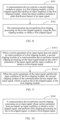
- FIG. 8 is a flowchart of a PAPR suppression method according to an embodiment of this application. As shown in FIG. 8 , the method may include the following steps.
- Step S701 A communication device controls a second clipping module to output, to a first clipping module, a to-be-clipped signal that satisfies an input condition of the first clipping module, where the input condition includes a peak distribution feature of an input signal.
- Step S702 The communication device performs first clipping processing on the to-be-clipped signal by using the first clipping module, to obtain a first clipped signal.
- the communication device may determine, depending on whether a carrier parameter of the input signal satisfies the input condition of the first clipping module, whether to enable the second clipping module to perform second clipping processing on the input signal, where the input condition includes the peak distribution feature of the input signal.
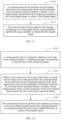
- FIG. 9 is a flowchart of a PAPR suppression method according to an embodiment of this application. As shown in FIG. 9 , in a possible implementation:
- the communication device when the carrier parameter of the input signal does not satisfy the input condition of the first clipping module 11, the communication device performs, by using the second clipping module 12, second clipping processing on the input signal based on the carrier parameter of the input signal and the input condition, to obtain the to-be-clipped signal, where a carrier parameter of the to-be-clipped signal may satisfy the input condition of the first clipping module. Then, the first clipping module 11 is used to perform first clipping processing on the to-be-clipped signal, to obtain the first clipped signal.
- the communication device When the carrier parameter of the input signal satisfies the input condition of the first clipping module 11, the communication device directly outputs the input signal, which is used as the to-be-clipped signal, to the first clipping module 11 by using the second clipping module 12, and then performs first clipping processing on the to-be-clipped signal by using the first clipping module 11, to obtain the first clipped signal.
- an adaptive clipping process is implemented based on collaboration between the two clipping modules.
- This implementation is simple and is applicable to more application scenarios.
- the communication device may determine, depending on whether the carrier parameter of the input signal satisfies the input condition of the first clipping module 11, whether to enable the second clipping module 12 to perform second clipping processing on the input signal.
- a communication device controls a second clipping module to output, to a first clipping module, a to-be-clipped signal that satisfies an input condition of the first clipping module may include: When the carrier parameter of the input signal satisfies the input condition of the first clipping module, the communication device skips enabling the second clipping module. When the carrier parameter of the input signal satisfies the input condition of the first clipping module 11, the communication device may skip enabling the second clipping module 12 to perform clipping processing on the input signal, that is, disable clipping processing performed on the input signal. In other words, when the carrier parameter of the input signal satisfies the input condition of the first clipping module 11, the second clipping module 12 in the communication device outputs the input signal, which is used as the to-be-clipped signal, to the first clipping module 11.
- the communication device For the input signal that satisfies the input condition, the communication device performs first clipping processing on the input signal by using the first clipping module 11, where the input condition includes the peak distribution feature of the input signal.
- the peak distribution feature of the input signal may include a statistical feature of peak distribution of the input signal, for example, an inter-carrier power ratio of the input signal, a modulation scheme of a carrier, or a spectrum occupation status of a carrier that are obtained through statistics collection.
- the communication device may configure a corresponding clipping parameter in the first clipping module 11 based on the statistical feature of the peak distribution of the input signal.
- the communication device may perform first clipping processing on the input signal based on the carrier parameter of the input signal and the clipping parameter
- a communication device controls a second clipping module to output, to a first clipping module, a to-be-clipped signal that satisfies an input condition of the first clipping module may further include: When the carrier parameter of the input signal does not satisfy the input condition of the first clipping module 11, the communication device controls the second clipping module to perform second clipping processing on the input signal based on the carrier parameter of the input signal and the input condition, to obtain the to-be-clipped signal. When the carrier parameter of the input signal does not satisfy the input condition of the first clipping module 11, the communication device may determine to enable the second clipping module 12 to perform second clipping processing on the input signal based on the carrier parameter of the input signal and the input condition.
- second clipping processing may be performed on the input signal based on a difference between the carrier parameter of the input signal and the input condition, to obtain the to-be-clipped signal, where the carrier parameter of the to-be-clipped signal satisfies the input condition.
- the first clipping module 11 performs first clipping processing on the to-be-clipped signal based on the clipping parameter corresponding to the input condition, to obtain the first clipped signal.
- PAPR suppression is performed based on collaboration between the two clipping modules.
- the foregoing implementation of this application is applicable to a plurality of scenarios. It is ensured that no clipping is missed, a PAPR is controllable, and a power amplifier is protected.
- this manner of pre-configuring a clipping parameter based on a statistical feature in this application is simpler. This resolves a technical problem that a static clipping algorithm is excessively complex or an application scenario is limited in the related technology.
- the method further includes: When the communication device controls the second clipping module to work in a bypass mode, the second clipping module outputs the received input signal to an input end of the first clipping module.
- the communication device performs, by using the first clipping module, third clipping processing on the input signal based on a clipping parameter corresponding to the carrier parameter of the input signal, where the clipping parameter is configured for different carriers based on a statistical feature of peak distribution of the input signal.
- the communication device may set a broad input condition of the first clipping module 11, so that all input signals can satisfy the input condition.
- the communication device may control the second clipping module 12 to work in the bypass mode, perform no processing on the input signal, and output the received input signal to the first clipping module 11.
- the second clipping module 12 is represented by a dashed box, and works in the bypass mode.
- the corresponding clipping parameter may be configured in the first clipping module 11 based on a statistical feature that is of peak distribution of the input signal and that is obtained through statistics collection.
- the statistical feature of the peak distribution may be a feature of a carrier, for example, an inter-carrier power configuration, a modulation scheme of the carrier, or a spectrum occupation status of the carrier.
- different clipping parameters may be configured for different carriers based on the statistical feature of the peak distribution of the input signal.
- the first clipping module 11 may adaptively adjust a weighting coefficient of clipping noise based on the carrier parameter of the input signal and a clipping parameter configured based on a carrier feature, and perform clipping processing on the input signal based on the weighting coefficient of the clipping noise.
- the carrier parameter may be an inter-carrier power ratio
- the clipping parameter may be a weighting coefficient of clipping noise. That the communication device performs, by using the first clipping module, clipping processing on the input signal based on a clipping parameter corresponding to the carrier parameter of the input signal includes: The communication device performs, by using the first clipping module, clipping processing on the input signal based on the weighting coefficient that is of the clipping noise and that corresponds to the inter-carrier power ratio.
- adaptive weighted allocation on the clipping noise by the first clipping module 11 is implemented in a manner of configuring different clipping parameters for different carrier configurations based on the statistical feature of the peak distribution of the input signal.
- the foregoing implementation of this application is applicable to a plurality of scenarios. It is ensured that no clipping is missed, the PAPR is controllable, and the power amplifier is protected. In comparison with the manner in which each peak value needs to be extracted for clipping processing in the strict scenario, this manner of pre-configuring the clipping parameter based on the statistical feature in this application is simpler.
- the clipping noise may be adaptively allocated based on the inter-carrier power ratio, so that the clipping noise is better allocated, to ensure system performance.
- the PAPR suppression apparatus in the implementations shown in FIG. 8 and FIG. 9 may alternatively include a plurality of different implementations.
- the first clipping module 11 may be an adaptive clipping module or may not be an adaptive clipping module
- the second clipping module 12 may be a module that adaptively enables clipping.
- the input condition of the first clipping module is a static first inter-carrier statistical feature
- the method further includes: The communication device configures, in the first clipping module based on the first inter-carrier statistical feature, a clipping parameter corresponding to the first inter-carrier statistical feature.
- the first inter-carrier statistical feature may be a long-term statistical feature between carriers of a signal.
- the communication device may configure a corresponding static clipping parameter in the first clipping module 11 based on the first inter-carrier statistical feature, and the static clipping parameter is not updated after being configured. In this way, the communication device may search for the corresponding static clipping parameter based on the carrier parameter of the input signal, and perform clipping on the input signal based on the found static clipping parameter by using the first clipping module 11.
- step S7011 in which the second clipping module 12 of the communication device performs second clipping processing on the input signal based on the carrier parameter of the input signal and the input condition when the carrier parameter of the input signal does not satisfy the input condition of the first clipping module, to obtain the to-be-clipped signal may include: The second clipping module of the communication device performs second clipping processing on the input signal based on the carrier parameter of the input signal and the first inter-carrier statistical feature when the carrier parameter of the input signal does not satisfy the first inter-carrier statistical feature, to obtain the to-be-clipped signal, where the carrier parameter of the to-be-clipped signal satisfies the first inter-carrier statistical feature.
- Step S702 in which the communication device performs first clipping processing on the to-be-clipped signal by using the first clipping module, to obtain a first clipped signal may include: The communication device performs, by using the first clipping module, first clipping processing on the to-be-clipped signal based on the clipping parameter corresponding to the first inter-carrier statistical feature, to obtain the first clipped signal.
- the communication device performs, by using the second clipping module 12, second clipping processing on the input signal whose carrier parameter does not satisfy the first inter-carrier statistical feature, to clip a part of peak values of a high-power carrier in advance.
- the to-be-clipped signal input into the first clipping module 11 satisfies an entry condition (the first inter-carrier statistical feature) of the first clipping module 11, and the communication device may perform first clipping processing on the to-be-clipped signal by using the clipping parameter configured by the first clipping module based on the first inter-carrier statistical feature, so that no clipping is missed.
- PAPR suppression method in the foregoing implementation of this application, according to a process in which the second clipping module 12 adaptively enables clipping processing based on a relationship between the input signal and the first inter-carrier statistical feature and performs clipping processing on the input signal, PAPR control of a signal in any scenario is applicable, and an implementation is simple.
- the input condition of the first clipping module is a dynamic second inter-carrier statistical feature
- the method further includes: The communication device periodically obtains a new second carrier statistical feature, and configures, in the first clipping module based on the new second carrier statistical feature, a clipping parameter corresponding to the second carrier statistical feature.
- the second inter-carrier statistical feature may be a short-term inter-carrier statistical feature obtained through periodic statistics collection.
- the communication device may configure, in the first clipping module 11, a corresponding clipping parameter based on a new second inter-carrier statistical feature obtained through statistics collection in each periodicity, in other words, periodically update the configured clipping parameter based on a statistical periodicity. Duration of each periodicity may be determined based on a specific application scenario. This is not limited in this application. Therefore, the first clipping module 11 may also perform adaptive clipping processing on the input signal as time changes.
- step S7011 in which the second clipping module 12 of the communication device performs second clipping processing on the input signal based on the carrier parameter of the input signal and the input condition when the carrier parameter of the input signal does not satisfy the input condition of the first clipping module, to obtain the to-be-clipped signal may include: When the carrier parameter of the input signal does not satisfy the second inter-carrier statistical feature, the second clipping module 12 of the communication device performs second clipping processing on the input signal based on the carrier parameter of the input signal and the second inter-carrier statistical feature, to obtain the to-be-clipped signal, where the carrier parameter of the to-be-clipped signal satisfies the second inter-carrier statistical feature.
- Step S702 in which the communication device performs first clipping processing on the to-be-clipped signal by using the first clipping module, to obtain a first clipped signal may include: The communication device performs, by using the first clipping module, first clipping processing on the to-be-clipped signal based on the clipping parameter corresponding to the second inter-carrier statistical feature, to obtain the first clipped signal.
- a process in which the second clipping module 12 processes the input signal is the same as a processing process in the foregoing implementation, except that the second inter-carrier statistical feature also changes with time when whether the carrier parameter of the input signal satisfies the second inter-carrier statistical feature is determined as time changes.
- the second clipping module 12 performs second clipping processing on the input signal, a referred second inter-carrier statistical feature also periodically changes with time.
- the first clipping module 11 periodically collects statistics of an inter-carrier feature of the input signal, and updates, based on the inter-carrier feature obtained through statistics collection, the second inter-carrier statistical feature and the corresponding clipping parameter that are locally configured, so that adaptive clipping processing can also be implemented.
- PAPR control of a signal in any scenario is applicable, and an implementation is simple.
- the carrier parameter of the input signal, the first inter-carrier statistical feature, and the second carrier statistical feature each are an inter-carrier power ratio.
- the carrier parameter of the input signal, the first inter-carrier statistical feature, and the second carrier statistical feature each may be another carrier feature such as a modulation scheme or a spectrum occupation status of a carrier. This is not limited in this application.
- This application further provides a PAPR suppression method, applied to a communication device.
- the communication device may be the RRU or the AAU described above, or may be the communication device shown in FIG. 3 or FIG. 7 . This is not limited in this application.
- FIG. 10 is a flowchart of a PAPR suppression method according to an embodiment of this application. As shown in FIG. 10 , the PAPR suppression method in this application may include the following steps.
- Step S100 A communication device performs second clipping processing on an input signal whose carrier parameter does not satisfy an input condition, to obtain a to-be-clipped signal, and performs first clipping processing on the to-be-clipped signal, to obtain a first clipped signal.
- the input condition includes a peak distribution feature of an input signal, and a carrier parameter of the to-be-clipped signal satisfies the input condition.
- the peak distribution feature of the input signal may include a statistical feature of peak distribution of the input signal.
- the peak distribution feature of the input signal is mainly affected by factors such as an inter-carrier power ratio of the input signal, a modulation scheme of a carrier, and a spectrum occupation status.
- the communication device configures a clipping parameter based on the statistical feature (the input condition) of the peak distribution of the input signal, performs second clipping processing on the input signal when the carrier parameter of the input signal does not satisfy the input condition, to obtain the to-be-clipped signal that satisfies the input condition, and then performs first clipping processing based on the clipping parameter corresponding to the input condition, to obtain the first clipped signal.
- preprocessing (second clipping processing) is performed on the input signal that does not satisfy the peak distribution feature, to obtain the to-be-clipped signal that satisfies the peak distribution feature, and then first clipping processing is performed on the to-be-clipped signal, to obtain the first clipped signal.
- second clipping processing is performed on the input signal that does not satisfy the peak distribution feature, to obtain the to-be-clipped signal that satisfies the peak distribution feature
- first clipping processing is performed on the to-be-clipped signal, to obtain the first clipped signal.
- this manner of pre-configuring a clipping parameter based on a statistical feature and preprocessing the input signal in this application is simpler. This resolves a technical problem that a static clipping algorithm is excessively complex or an application scenario is limited in the related technology.
- FIG. 11 is a flowchart of a PAPR suppression method according to an implementation of this application.
- the method may include the following steps.
- Step S110 A communication device performs second clipping processing on an input signal whose carrier parameter does not satisfy an input condition, to obtain a to-be-clipped signal, and performs first clipping processing on the to-be-clipped signal, to obtain a first clipped signal.
- Step S111 The communication device performs first clipping processing on an input signal whose carrier parameter satisfies the input condition, to obtain the first clipped signal.
- step S110 For a process of step S110, refer to the foregoing descriptions of step S100. Details are not described again.
- the communication device may directly perform first clipping processing on the input signal, to obtain the first clipped signal.
- the PAPR suppression method in the foregoing implementation of this application different clipping processes are used for the input signal based on a relationship between the carrier parameter of the input signal and the input condition.
- the foregoing implementation of this application is applicable to a plurality of scenarios. It is ensured that no clipping is missed, a PAPR is controllable, and a power amplifier is protected.
- this manner of pre-configuring a clipping parameter based on a statistical feature and preprocessing the input signal in this application is simpler. This resolves a technical problem that a static clipping algorithm is excessively complex or an application scenario is limited in the related technology.
- step S100 (S110) in which a communication device performs second clipping processing on an input signal whose carrier parameter does not satisfy an input condition, to obtain a to-be-clipped signal may include: The communication device performs second clipping processing on the input signal based on the carrier parameter of the input signal and the input condition when the carrier parameter of the input signal does not satisfy the input condition, to obtain the to-be-clipped signal.
- the communication device may perform second clipping processing based on a difference between the carrier parameter of the input signal and the input condition.
- the input condition is an inter-carrier power ratio.
- the clipping parameter is configured based on an inter-carrier power ratio 1:1.
- first clipping processing may be performed on the input signal based on the configured clipping parameter.
- the communication device may perform second clipping processing on the input signal, to clip a part of peak values of a high-power carrier in advance, so that no clipping is missed even if first clipping processing is performed, based on the weighting coefficient that is of the clipping noise and that is configured when the inter-carrier power ratio is 1:1, on the to-be-clipped signal that enters the first clipping module after second clipping processing.
- PAPR suppression method in the foregoing implementation of this application, according to a process in which second clipping processing is adaptively enabled based on a relationship between the input signal and the input condition and second clipping processing is performed on the input signal, PAPR control of a signal in any scenario is applicable, and an implementation is simple.
- FIG. 12 is a flowchart of a PAPR suppression method according to an implementation of this application.
- Step S100 may include: Step S121: When the carrier parameter of the input signal does not satisfy the first inter-carrier statistical feature, the communication device performs second clipping processing on the input signal based on the carrier parameter of the input signal and the first inter-carrier statistical feature, to obtain the to-be-clipped signal, where a carrier parameter of the to-be-clipped signal satisfies the first inter-carrier statistical feature.
- step S111 in which the communication device performs first clipping processing on the to-be-clipped signal, to obtain a first clipped signal may include: Step S122: The communication device performs first clipping processing on the to-be-clipped signal based on a clipping parameter corresponding to the first inter-carrier statistical feature, to obtain the first clipped signal.
- the method may further include: Step S120: The communication device configures, based on the first inter-carrier statistical feature, the clipping parameter corresponding to the first inter-carrier statistical feature.
- the first inter-carrier statistical feature may be a long-term statistical feature between carriers of a signal.
- the communication device may configure a corresponding static clipping parameter based on the first inter-carrier statistical feature. After configuration, the first inter-carrier statistical feature and the corresponding static clipping parameter are no longer updated. In this way, the communication device may search for the corresponding static clipping parameter based on the carrier parameter of the input signal, and perform first clipping processing on the input signal based on the found static clipping parameter.
- the communication device may further perform second clipping processing on the input signal based on the carrier parameter of the input signal and the first inter-carrier statistical feature, to obtain the to-be-clipped signal, where the carrier parameter of the to-be-clipped signal satisfies the first inter-carrier statistical feature. Then, the communication device further performs first clipping processing on the to-be-clipped signal based on the clipping parameter corresponding to the first inter-carrier statistical feature, to obtain the first clipped signal.
- PAPR suppression method in the foregoing implementation of this application, according to a process in which clipping processing is adaptively enabled based on a relationship between the input signal and the first inter-carrier statistical feature and clipping processing is performed on the input signal, PAPR control of a signal in any scenario is applicable, and an implementation is simple.
- FIG. 13 is a flowchart of a PAPR suppression method according to an implementation of this application.
- the input condition is a dynamic second carrier statistical feature.
- the method may include: Step S130: The communication device periodically obtains a new second carrier statistical feature, and configures, based on the new second carrier statistical feature, a clipping parameter corresponding to the new second carrier statistical feature.
- Step S100 may include: Step S131: When the carrier parameter of the input signal does not satisfy the second inter-carrier statistical feature, the communication device performs second clipping processing on the input signal based on the carrier parameter of the input signal and the second inter-carrier statistical feature, to obtain the to-be-clipped signal, where a carrier parameter of the to-be-clipped signal satisfies the second inter-carrier statistical feature.
- Step S111 in which the communication device performs first clipping processing on the to-be-clipped signal, to obtain a first clipped signal may include: Step S132: The communication device performs first clipping processing on the to-be-clipped signal based on the clipping parameter corresponding to the second inter-carrier statistical feature, to obtain the first clipped signal.
- the second inter-carrier statistical feature may be a short-term inter-carrier statistical feature obtained through periodic statistics collection.
- the communication device may configure a corresponding clipping parameter based on a new second inter-carrier statistical feature obtained through statistics collection in each periodicity, in other words, periodically update the configured clipping parameter based on a statistical periodicity. Duration of each periodicity may be determined based on a specific application scenario. This is not limited in this application. Therefore, first clipping processing may alternatively be a process in which adaptive clipping processing is performed on the input signal as time changes.
- a specific process of second clipping processing in step S131 is the same as a processing process described above, except that the second inter-carrier statistical feature also changes with time when whether the carrier parameter of the input signal satisfies the second inter-carrier statistical feature is determined as time changes.
- a referred second inter-carrier statistical feature also periodically changes with time.
- the method includes: The communication device performs third clipping processing on the input signal based on a clipping parameter corresponding to the carrier parameter of the input signal.
- the clipping parameter is configured for different carriers based on a statistical feature of peak distribution of the input signal.
- the carrier parameter is an inter-carrier power ratio
- the clipping parameter is a weighting coefficient of clipping noise.
- the corresponding clipping parameter may be configured based on a statistical feature that is of peak distribution of the input signal and that is obtained through statistics collection.
- the statistical feature of the peak distribution may be a feature of a carrier, for example, an inter-carrier power configuration, a modulation scheme of the carrier, and a spectrum occupation status of the carrier.
- different clipping parameters may be configured for different carriers based on the statistical feature of the peak distribution of the input signal.
- the communication device may adaptively adjust a weighting coefficient of clipping noise based on the carrier parameter of the input signal and a clipping parameter configured based on a carrier feature, and perform clipping processing on the input signal based on the weighting coefficient of the clipping noise.
- adaptive weighted allocation on the clipping noise is implemented by the communication device in a manner of configuring different clipping parameters for different carrier configurations based on the statistical feature of the peak distribution of the input signal.
- the foregoing implementation of this application is applicable to a plurality of scenarios. It is ensured that no clipping is missed, the PAPR is controllable, and the power amplifier is protected. In comparison with the manner in which each peak value needs to be extracted for clipping processing in the strict scenario, this manner of pre-configuring the clipping parameter based on the statistical feature in this application is simpler.
- FIG. 14 is a block diagram of a PAPR suppression apparatus according to an embodiment of this application.
- the apparatus may include: a clipping unit 1400, configured to perform second clipping processing on an input signal whose carrier parameter does not satisfy an input condition, to obtain a to-be-clipped signal, and perform first clipping processing on the to-be-clipped signal, to obtain a first clipped signal, where the input condition includes a peak distribution feature of an input signal, and a carrier parameter of the to-be-clipped signal satisfies the input condition.
- the PAPR suppression apparatus in this application performs preprocessing (second clipping processing) on the input signal that does not satisfy the peak distribution feature, to obtain the to-be-clipped signal that satisfies the peak distribution feature, and then performs first clipping processing on the to-be-clipped signal, to obtain the first clipped signal.
- preprocessing second clipping processing
- first clipping processing on the to-be-clipped signal, to obtain the first clipped signal.
- this manner of pre-configuring a clipping parameter based on a statistical feature and preprocessing the input signal in this application is simpler. This resolves a technical problem that a static clipping algorithm is excessively complex or an application scenario is limited in the related technology.
- the clipping unit 1400 includes a second clipping module, configured to: perform second clipping processing on the input signal based on the carrier parameter of the input signal and the input condition when the carrier parameter of the input signal does not satisfy the input condition, to obtain the to-be-clipped signal.
- the apparatus further includes a first clipping module, configured to perform first clipping processing on an input signal whose carrier parameter satisfies the input condition, to obtain the first clipped signal.
- the apparatus further includes a third clipping module, configured to perform third clipping processing on the input signal based on a clipping parameter corresponding to the carrier parameter of the input signal, where the clipping parameter is configured for different carriers based on a statistical feature of peak distribution of the input signal.
- a third clipping module configured to perform third clipping processing on the input signal based on a clipping parameter corresponding to the carrier parameter of the input signal, where the clipping parameter is configured for different carriers based on a statistical feature of peak distribution of the input signal.
- the carrier parameter is an inter-carrier power ratio
- the clipping parameter is a weighting coefficient of clipping noise
- adaptive weighted allocation on the clipping noise is implemented by the communication device in a manner of configuring different clipping parameters for different carrier configurations based on the statistical feature of the peak distribution of the input signal.
- the foregoing implementation of this application is applicable to a plurality of scenarios. It is ensured that no clipping is missed, the PAPR is controllable, and the power amplifier is protected. In comparison with the manner in which each peak value needs to be extracted for clipping processing in the strict scenario, this manner of pre-configuring the clipping parameter based on the statistical feature in this application is simpler.
- the input condition is a static first inter-carrier statistical feature.
- the second clipping module is further configured to: when the carrier parameter of the input signal does not satisfy the first inter-carrier statistical feature, perform second clipping processing on the input signal based on the carrier parameter of the input signal and the first inter-carrier statistical feature, to obtain the to-be-clipped signal.
- the first clipping module is configured to perform first clipping processing on the to-be-clipped signal based on a clipping parameter corresponding to the first inter-carrier statistical feature, to obtain the first clipped signal.
- the apparatus further includes a first configuration module, configured to configure, based on the first inter-carrier statistical feature, the clipping parameter corresponding to the first inter-carrier statistical feature.
- PAPR control of a signal in any scenario is applicable, and an implementation is simple.
- the input condition is a dynamic second carrier statistical feature.
- the apparatus further includes a second configuration module, configured to periodically obtain a new second carrier statistical feature, and configure, based on the new second carrier statistical feature, a clipping parameter corresponding to the new second carrier statistical feature.
- the second clipping module is further configured to: when the carrier parameter of the input signal does not satisfy the second inter-carrier statistical feature, perform second clipping processing on the input signal based on the carrier parameter of the input signal and the second inter-carrier statistical feature, to obtain the to-be-clipped signal.
- the first clipping module is further configured to perform first clipping processing on the to-be-clipped signal based on a clipping parameter corresponding to the second inter-carrier statistical feature, to obtain the first clipped signal.
- the carrier parameter of the input signal, the first inter-carrier statistical feature, and the second carrier statistical feature each are an inter-carrier power ratio.
- An embodiment of this application provides a PAPR suppression apparatus, including a processor and a memory for storing executable instructions of the processor.
- the processor is configured to implement the foregoing method when executing the instructions.
- An embodiment of this application provides a non-volatile computer-readable storage medium, storing computer program instructions.
- the computer program instructions are executed by a processor, the foregoing method is implemented.
- An embodiment of this application provides a computer program product, including computer-readable code or a non-volatile computer-readable storage medium carrying computer-readable code.
- the computer-readable code When the computer-readable code is run on a processor in an electronic device, the processor in the electronic device performs the foregoing method.
- the computer-readable storage medium may be a tangible device that may retain and store instructions for use by an instruction execution device.
- the computer-readable storage medium may be, for example, but is not limited to, an electrical storage device, a magnetic storage device, an optical storage device, an electromagnetic storage device, a semiconductor storage device, or any suitable combination thereof.
- the computer-readable storage medium includes a portable computer disk, a hard disk, a random access memory (Random Access Memory, RAM), a read-only memory (Read-Only Memory, ROM), an erasable programmable read-only memory (Erasable Programmable Read-Only Memory, EPROM or a flash memory), a static random access memory (Static Random Access Memory, SRAM), a portable compact disc read-only memory (Compact Disc Read-Only Memory, CD-ROM), a digital versatile disc (Digital Versatile Disc, DVD), a memory stick, a floppy disk, a mechanical encoded device such as a punched card or a groove protrusion structure storing instructions, and any suitable combination thereof.
- the computer-readable program instructions or code described herein may be downloaded from a computer-readable storage medium to each computing/processing device, or downloaded to an external computer or an external storage device over a network, such as the Internet, a local area network, a wide area network, and/or a wireless network.
- the network may include copper transmission cables, optical fiber transmission, wireless transmission, routers, firewalls, switches, gateway computers, and/or edge servers.
- a network adapter card or a network interface in each computing/processing device receives computer-readable program instructions from a network, and forwards the computer-readable program instructions for storage in a computer-readable storage medium in each computing/processing device.
- the computer program instructions used to perform operations in this application may be assembly instructions, instruction set architecture (Instruction Set Architecture, ISA) instructions, machine instructions, machine-related instructions, microcode, firmware instructions, status setting data, or source code or target code written in one or any combination of more programming languages.
- the programming languages include object-oriented programming languages such as Smalltalk and C++, and a conventional procedural programming language such as "C" or a similar programming language.
- the computer-readable program instructions may be executed entirely on a user computer, partly on the user computer, as a stand-alone software package, partly on the user computer and partly on a remote computer, or entirely on the remote computer or a server.
- the remote computer When a remote computer is involved, the remote computer may be connected to a user computer over any type of network, including a local area network (Local Area Network, LAN) or a wide area network (Wide Area Network, WAN), or may be connected to an external computer (for example, connected by using an Internet service provider over the Internet).
- an electronic circuit for example, a programmable logic circuit, a field programmable gate array (Field Programmable Gate Array, FPGA), or a programmable logic array (Programmable Logic Array, PLA), is customized by using status information of computer-readable program instructions.
- the electronic circuit may execute the computer-readable program instructions, to implement various aspects of this application.
- These computer-readable program instructions may be provided to a processor of a general-purpose computer, a dedicated computer, or another programmable data processing apparatus to produce a machine, so that the instructions, when executed by the processor of the computer or the another programmable data processing apparatus, create an apparatus for implementing functions/actions specified in one or more blocks in the flowcharts and/or the block diagrams.
- these computer-readable program instructions may be stored in a computer-readable storage medium. These instructions enable a computer, a programmable data processing apparatus, and/or another device to work in a specific manner Therefore, the computer-readable medium storing the instructions includes an artifact that includes instructions for implementing various aspects of functions/actions specified in one or more blocks in the flowcharts and/or the block diagrams.
- these computer-readable program instructions may be loaded onto a computer, another programmable data processing apparatus, or another device, so that a series of operation steps are performed on the computer, the another programmable data processing apparatus, or the another device to produce a computer-implemented process. Therefore, the instructions executed on the computer, the another programmable data processing apparatus, or the another device implements functions/actions specified in one or more blocks in the flowcharts and/or the block diagrams.
- each block in the flowcharts or the block diagrams may represent a module, a program segment, or a part of the instructions, where the module, the program segment, or the part of the instructions includes one or more executable instructions for implementing a specified logical function.
- the functions marked in the blocks may also occur in a sequence different from that marked in the accompanying drawings. For example, two consecutive blocks may actually be executed substantially in parallel, and sometimes may be executed in a reverse order, depending on a function involved.
- each block in the block diagrams and/or the flowcharts and a combination of blocks in the block diagrams and/or the flowcharts may be implemented by hardware (for example, a circuit or an ASIC (Application-Specific Integrated Circuit, application-specific integrated circuit)) that performs a corresponding function or action, or may be implemented by a combination of hardware and software, for example, firmware.
- hardware for example, a circuit or an ASIC (Application-Specific Integrated Circuit, application-specific integrated circuit)
- ASIC Application-Specific Integrated Circuit, application-specific integrated circuit
Landscapes
- Engineering & Computer Science (AREA)
- Computer Networks & Wireless Communication (AREA)
- Signal Processing (AREA)
- Transmitters (AREA)
- Amplifiers (AREA)
Applications Claiming Priority (1)
| Application Number | Priority Date | Filing Date | Title |
|---|---|---|---|
| PCT/CN2020/132856 WO2022110177A1 (zh) | 2020-11-30 | 2020-11-30 | 自适应峰均比papr抑制装置、方法以及通信设备 |
Publications (2)
| Publication Number | Publication Date |
|---|---|
| EP4236221A1 true EP4236221A1 (de) | 2023-08-30 |
| EP4236221A4 EP4236221A4 (de) | 2023-12-27 |
Family
ID=81755202
Family Applications (1)
| Application Number | Title | Priority Date | Filing Date |
|---|---|---|---|
| EP20963065.6A Pending EP4236221A4 (de) | 2020-11-30 | 2020-11-30 | Vorrichtung und verfahren zur papr-unterdrückung mit adaptivem spitzen-zu-durchschnitts-verhältnis und kommunikationsvorrichtung |
Country Status (4)
| Country | Link |
|---|---|
| US (1) | US20230308333A1 (de) |
| EP (1) | EP4236221A4 (de) |
| CN (1) | CN116530061B (de) |
| WO (1) | WO2022110177A1 (de) |
Cited By (1)
| Publication number | Priority date | Publication date | Assignee | Title |
|---|---|---|---|---|
| EP4307571A4 (de) * | 2021-03-30 | 2024-04-17 | Huawei Technologies Co., Ltd. | Signalverarbeitungsverfahren und kommunikationsvorrichtung |
Families Citing this family (2)
| Publication number | Priority date | Publication date | Assignee | Title |
|---|---|---|---|---|
| US12261728B2 (en) * | 2022-10-18 | 2025-03-25 | Qualcomm Incorporated | DMRS with dynamic and controllable PAPR properties |
| CN121125426B (zh) * | 2025-11-13 | 2026-03-17 | 北京广世无限科技有限责任公司 | 基于频域子载波贡献度量的选择性降papr方法及系统 |
Family Cites Families (21)
| Publication number | Priority date | Publication date | Assignee | Title |
|---|---|---|---|---|
| US6760452B2 (en) * | 2002-10-24 | 2004-07-06 | Visteon Global Technologies, Inc. | Multi-channel audio signal limiter with shared clip detection |
| CN100591058C (zh) * | 2003-05-30 | 2010-02-17 | 华为技术有限公司 | 一种信号削波装置及方法 |
| US7583583B2 (en) * | 2005-12-15 | 2009-09-01 | Nortel Networks Limited | System and method for reducing peak-to-average power ratio in orthogonal frequency division multiplexing signals using reserved spectrum |
| JP2007194825A (ja) * | 2006-01-18 | 2007-08-02 | Fujitsu Ltd | マルチキャリア信号送信装置 |
| US8073073B2 (en) * | 2006-10-30 | 2011-12-06 | Quantenna Communications, Inc. | Optimized clipping for peak-to-average power ratio reduction |
| CN101257481B (zh) * | 2008-04-22 | 2012-09-05 | 中兴通讯股份有限公司 | 一种预处理不连续配置多载波的削峰系统和方法 |
| JP5291668B2 (ja) * | 2010-01-13 | 2013-09-18 | 株式会社エヌ・ティ・ティ・ドコモ | 送信機及びmimo多重伝送方法 |
| US8583061B2 (en) * | 2011-11-04 | 2013-11-12 | Motorola Solutions, Inc. | Peak suppression on multicarrier |
| KR101512543B1 (ko) * | 2012-04-27 | 2015-04-15 | 삼성전기주식회사 | 피크 억제 기능을 갖는 베이스 밴드 처리기, 송신 장치 및 송신 방법 |
| WO2014141335A1 (ja) * | 2013-03-15 | 2014-09-18 | 日本電気株式会社 | 通信装置及びそのピーク抑圧方法 |
| KR102094726B1 (ko) * | 2013-05-24 | 2020-03-30 | 삼성전자주식회사 | Ofdm 신호의 papr 저감 방법 및 장치, 송신 장치 |
| US9236899B2 (en) * | 2013-06-05 | 2016-01-12 | Telefonaktiebolaget L M Ericsson (Publ) | Crest factor reduction of inter-band carrier aggregated signals |
| US9178540B2 (en) * | 2014-02-02 | 2015-11-03 | Redline Innovations Group Inc. | Systems and methods for increasing the effectiveness of digital pre-distortion in electronic communications |
| US9537686B2 (en) * | 2014-04-03 | 2017-01-03 | Redline Communications Inc. | Systems and methods for increasing the effectiveness of digital pre-distortion in electronic communications |
| US9444669B2 (en) * | 2014-12-30 | 2016-09-13 | Texas Instruments Incorporated | Peak to average power ratio reduction of OFDM signals |
| US9819526B2 (en) * | 2015-11-05 | 2017-11-14 | Huawei Technologies Co., Ltd. | Apparatus and methods for low PAPR transmission in MIMO systems |
| CN108293032B (zh) * | 2015-12-17 | 2020-07-07 | 华为技术有限公司 | 一种削波方法及装置 |
| CN111107030B (zh) * | 2018-10-25 | 2022-07-12 | 北京新岸线移动多媒体技术有限公司 | 一种适用于大带宽系统的降低信号峰均比的方法及装置 |
| CN111107031B (zh) * | 2018-10-25 | 2022-09-20 | 北京新岸线移动多媒体技术有限公司 | 一种用于降低信号峰均比的方法及装置 |
| WO2020158040A1 (ja) * | 2019-01-31 | 2020-08-06 | 三菱電機株式会社 | 衛星送信機および中継衛星通信システム |
| CN111464476B (zh) * | 2020-03-10 | 2025-02-14 | 北京新岸线移动多媒体技术有限公司 | 一种削波方法及装置 |
-
2020
- 2020-11-30 WO PCT/CN2020/132856 patent/WO2022110177A1/zh not_active Ceased
- 2020-11-30 CN CN202080107024.0A patent/CN116530061B/zh active Active
- 2020-11-30 EP EP20963065.6A patent/EP4236221A4/de active Pending
-
2023
- 2023-05-30 US US18/325,955 patent/US20230308333A1/en active Pending
Cited By (2)
| Publication number | Priority date | Publication date | Assignee | Title |
|---|---|---|---|---|
| EP4307571A4 (de) * | 2021-03-30 | 2024-04-17 | Huawei Technologies Co., Ltd. | Signalverarbeitungsverfahren und kommunikationsvorrichtung |
| US12418448B2 (en) | 2021-03-30 | 2025-09-16 | Huawei Technologies Co., Ltd. | Signal processing method and communication apparatus |
Also Published As
| Publication number | Publication date |
|---|---|
| CN116530061B (zh) | 2025-10-10 |
| US20230308333A1 (en) | 2023-09-28 |
| EP4236221A4 (de) | 2023-12-27 |
| CN116530061A (zh) | 2023-08-01 |
| WO2022110177A1 (zh) | 2022-06-02 |
Similar Documents
| Publication | Publication Date | Title |
|---|---|---|
| US20230308333A1 (en) | Adaptive peak to average power ratio papr suppression apparatus and method, and communication device | |
| US20250330364A1 (en) | Data transmission method and apparatus, data modulation method and apparatus, electronic device, and storage medium | |
| RU2426231C2 (ru) | Способ управления мощностью передачи в зависимости от загрузки поддиапазона | |
| JP6592589B2 (ja) | スケジューリング方法および装置 | |
| WO2011104951A1 (ja) | ピーク電力抑制回路とこの回路を有する通信装置 | |
| CN112543156B (zh) | 多频段信号的数字预失真方法、电子设备和可读存储介质 | |
| CN110677856B (zh) | 一种ssb配置方案的规划方法及装置 | |
| You et al. | Out-of-band emission suppression techniques based on a generalized OFDM framework | |
| EP3379784A1 (de) | Schneidverfahren und -vorrichtung | |
| WO2020190185A1 (en) | Method and control device for mitigating interference | |
| WO2022248033A1 (en) | Projected signals using discrete prolate spheroidal sequences | |
| KR100909694B1 (ko) | 적응적 톤 예약 장치 및 방법 | |
| KR20240096814A (ko) | 데이터 전송 방법, 무선 주파수 장치, 및 제어 장치 | |
| US11777768B2 (en) | Pre-equalization compensation method and device for link, storage medium and electronic device | |
| Kumar et al. | Peak average power reduction in NOMA by using PTSCT technique | |
| CN119364449A (zh) | 通信方法及相关设备 | |
| US12424879B2 (en) | Efficient transfer of power in a wireless power transfer system | |
| CN111711594B (zh) | 一种单频干扰处理方法及装置 | |
| KR102799125B1 (ko) | 보호 부반송파를 구성하기 위한 방법 | |
| Luo et al. | Guardband optimization for cellular systems applying raised cosine windowed OFDM | |
| CN105245480B (zh) | 数字信号处理方法及装置 | |
| CN117714245B (zh) | 无线自组网系统中的干扰抑制系统、方法、设备及介质 | |
| Abdallah et al. | Evaluating the practical performance of energy detector based spectrum sensing for cognitive radio | |
| Karthickmanoj et al. | Evaluation of Filtering Techniques in Channel Estimation for MIMO-OFDM Systems | |
| CN113853027B (zh) | 一种提升option6移动性场景系统性能的方法和系统 |
Legal Events
| Date | Code | Title | Description |
|---|---|---|---|
| STAA | Information on the status of an ep patent application or granted ep patent |
Free format text: STATUS: THE INTERNATIONAL PUBLICATION HAS BEEN MADE |
|
| PUAI | Public reference made under article 153(3) epc to a published international application that has entered the european phase |
Free format text: ORIGINAL CODE: 0009012 |
|
| STAA | Information on the status of an ep patent application or granted ep patent |
Free format text: STATUS: REQUEST FOR EXAMINATION WAS MADE |
|
| 17P | Request for examination filed |
Effective date: 20230523 |
|
| AK | Designated contracting states |
Kind code of ref document: A1 Designated state(s): AL AT BE BG CH CY CZ DE DK EE ES FI FR GB GR HR HU IE IS IT LI LT LU LV MC MK MT NL NO PL PT RO RS SE SI SK SM TR |
|
| A4 | Supplementary search report drawn up and despatched |
Effective date: 20231129 |
|
| RIC1 | Information provided on ipc code assigned before grant |
Ipc: H04L 5/00 20060101ALI20231123BHEP Ipc: H04L 27/26 20060101AFI20231123BHEP |
|
| DAV | Request for validation of the european patent (deleted) | ||
| DAX | Request for extension of the european patent (deleted) |