EP4236044A2 - Machine électrique linéaire - Google Patents
Machine électrique linéaire Download PDFInfo
- Publication number
- EP4236044A2 EP4236044A2 EP23163192.0A EP23163192A EP4236044A2 EP 4236044 A2 EP4236044 A2 EP 4236044A2 EP 23163192 A EP23163192 A EP 23163192A EP 4236044 A2 EP4236044 A2 EP 4236044A2
- Authority
- EP
- European Patent Office
- Prior art keywords
- translator
- electrical machine
- stator
- bearing
- linear electrical
- Prior art date
- Legal status (The legal status is an assumption and is not a legal conclusion. Google has not performed a legal analysis and makes no representation as to the accuracy of the status listed.)
- Pending
Links
- 239000012530 fluid Substances 0.000 claims abstract description 114
- 230000036316 preload Effects 0.000 claims description 54
- 238000002485 combustion reaction Methods 0.000 claims description 8
- 230000004907 flux Effects 0.000 claims description 5
- 238000012360 testing method Methods 0.000 description 55
- 230000033001 locomotion Effects 0.000 description 32
- 239000007789 gas Substances 0.000 description 27
- 238000006073 displacement reaction Methods 0.000 description 11
- 239000007788 liquid Substances 0.000 description 6
- 238000005452 bending Methods 0.000 description 5
- 239000000725 suspension Substances 0.000 description 5
- 230000008859 change Effects 0.000 description 4
- 238000010276 construction Methods 0.000 description 4
- 239000000463 material Substances 0.000 description 4
- 230000008901 benefit Effects 0.000 description 3
- 238000001816 cooling Methods 0.000 description 3
- 230000002706 hydrostatic effect Effects 0.000 description 3
- 238000012905 input function Methods 0.000 description 3
- 239000000203 mixture Substances 0.000 description 3
- OKTJSMMVPCPJKN-UHFFFAOYSA-N Carbon Chemical compound [C] OKTJSMMVPCPJKN-UHFFFAOYSA-N 0.000 description 2
- 230000005540 biological transmission Effects 0.000 description 2
- 229910052799 carbon Inorganic materials 0.000 description 2
- 230000006835 compression Effects 0.000 description 2
- 238000007906 compression Methods 0.000 description 2
- 238000013016 damping Methods 0.000 description 2
- 238000011161 development Methods 0.000 description 2
- 230000000694 effects Effects 0.000 description 2
- 238000010348 incorporation Methods 0.000 description 2
- 230000010354 integration Effects 0.000 description 2
- 238000004519 manufacturing process Methods 0.000 description 2
- 230000003287 optical effect Effects 0.000 description 2
- 238000011084 recovery Methods 0.000 description 2
- 230000001105 regulatory effect Effects 0.000 description 2
- 230000004044 response Effects 0.000 description 2
- 230000003068 static effect Effects 0.000 description 2
- RYGMFSIKBFXOCR-UHFFFAOYSA-N Copper Chemical compound [Cu] RYGMFSIKBFXOCR-UHFFFAOYSA-N 0.000 description 1
- 230000009471 action Effects 0.000 description 1
- 230000000712 assembly Effects 0.000 description 1
- 238000000429 assembly Methods 0.000 description 1
- 230000015556 catabolic process Effects 0.000 description 1
- 238000006243 chemical reaction Methods 0.000 description 1
- 238000004891 communication Methods 0.000 description 1
- 230000001276 controlling effect Effects 0.000 description 1
- 229910052802 copper Inorganic materials 0.000 description 1
- 239000010949 copper Substances 0.000 description 1
- 125000004122 cyclic group Chemical group 0.000 description 1
- 238000006731 degradation reaction Methods 0.000 description 1
- 230000001419 dependent effect Effects 0.000 description 1
- 239000010720 hydraulic oil Substances 0.000 description 1
- 230000001771 impaired effect Effects 0.000 description 1
- 239000000696 magnetic material Substances 0.000 description 1
- 238000012423 maintenance Methods 0.000 description 1
- 239000003921 oil Substances 0.000 description 1
- 230000035699 permeability Effects 0.000 description 1
- 229920000642 polymer Polymers 0.000 description 1
- 239000011148 porous material Substances 0.000 description 1
- 238000005057 refrigeration Methods 0.000 description 1
- 230000000284 resting effect Effects 0.000 description 1
- 230000000717 retained effect Effects 0.000 description 1
- 238000005096 rolling process Methods 0.000 description 1
- 239000007787 solid Substances 0.000 description 1
- 230000003746 surface roughness Effects 0.000 description 1
- 239000002918 waste heat Substances 0.000 description 1
Images


Classifications
-
- G—PHYSICS
- G01—MEASURING; TESTING
- G01M—TESTING STATIC OR DYNAMIC BALANCE OF MACHINES OR STRUCTURES; TESTING OF STRUCTURES OR APPARATUS, NOT OTHERWISE PROVIDED FOR
- G01M7/00—Vibration-testing of structures; Shock-testing of structures
- G01M7/02—Vibration-testing by means of a shake table
-
- H—ELECTRICITY
- H02—GENERATION; CONVERSION OR DISTRIBUTION OF ELECTRIC POWER
- H02K—DYNAMO-ELECTRIC MACHINES
- H02K7/00—Arrangements for handling mechanical energy structurally associated with dynamo-electric machines, e.g. structural association with mechanical driving motors or auxiliary dynamo-electric machines
- H02K7/18—Structural association of electric generators with mechanical driving motors, e.g. with turbines
- H02K7/1869—Linear generators; sectional generators
- H02K7/1876—Linear generators; sectional generators with reciprocating, linearly oscillating or vibrating parts
- H02K7/1884—Linear generators; sectional generators with reciprocating, linearly oscillating or vibrating parts structurally associated with free piston engines
-
- H—ELECTRICITY
- H02—GENERATION; CONVERSION OR DISTRIBUTION OF ELECTRIC POWER
- H02K—DYNAMO-ELECTRIC MACHINES
- H02K7/00—Arrangements for handling mechanical energy structurally associated with dynamo-electric machines, e.g. structural association with mechanical driving motors or auxiliary dynamo-electric machines
- H02K7/08—Structural association with bearings
- H02K7/086—Structural association with bearings radially supporting the rotor around a fixed spindle; radially supporting the rotor directly
- H02K7/088—Structural association with bearings radially supporting the rotor around a fixed spindle; radially supporting the rotor directly radially supporting the rotor directly
-
- F—MECHANICAL ENGINEERING; LIGHTING; HEATING; WEAPONS; BLASTING
- F02—COMBUSTION ENGINES; HOT-GAS OR COMBUSTION-PRODUCT ENGINE PLANTS
- F02B—INTERNAL-COMBUSTION PISTON ENGINES; COMBUSTION ENGINES IN GENERAL
- F02B71/00—Free-piston engines; Engines without rotary main shaft
- F02B71/04—Adaptations of such engines for special use; Combinations of such engines with apparatus driven thereby
-
- F—MECHANICAL ENGINEERING; LIGHTING; HEATING; WEAPONS; BLASTING
- F16—ENGINEERING ELEMENTS AND UNITS; GENERAL MEASURES FOR PRODUCING AND MAINTAINING EFFECTIVE FUNCTIONING OF MACHINES OR INSTALLATIONS; THERMAL INSULATION IN GENERAL
- F16C—SHAFTS; FLEXIBLE SHAFTS; ELEMENTS OR CRANKSHAFT MECHANISMS; ROTARY BODIES OTHER THAN GEARING ELEMENTS; BEARINGS
- F16C32/00—Bearings not otherwise provided for
- F16C32/06—Bearings not otherwise provided for with moving member supported by a fluid cushion formed, at least to a large extent, otherwise than by movement of the shaft, e.g. hydrostatic air-cushion bearings
-
- G—PHYSICS
- G01—MEASURING; TESTING
- G01M—TESTING STATIC OR DYNAMIC BALANCE OF MACHINES OR STRUCTURES; TESTING OF STRUCTURES OR APPARATUS, NOT OTHERWISE PROVIDED FOR
- G01M17/00—Testing of vehicles
- G01M17/007—Wheeled or endless-tracked vehicles
-
- G—PHYSICS
- G01—MEASURING; TESTING
- G01M—TESTING STATIC OR DYNAMIC BALANCE OF MACHINES OR STRUCTURES; TESTING OF STRUCTURES OR APPARATUS, NOT OTHERWISE PROVIDED FOR
- G01M17/00—Testing of vehicles
- G01M17/007—Wheeled or endless-tracked vehicles
- G01M17/04—Suspension or damping
-
- H—ELECTRICITY
- H01—ELECTRIC ELEMENTS
- H01F—MAGNETS; INDUCTANCES; TRANSFORMERS; SELECTION OF MATERIALS FOR THEIR MAGNETIC PROPERTIES
- H01F7/00—Magnets
- H01F7/06—Electromagnets; Actuators including electromagnets
- H01F7/08—Electromagnets; Actuators including electromagnets with armatures
- H01F7/16—Rectilinearly-movable armatures
- H01F7/1607—Armatures entering the winding
-
- H—ELECTRICITY
- H02—GENERATION; CONVERSION OR DISTRIBUTION OF ELECTRIC POWER
- H02K—DYNAMO-ELECTRIC MACHINES
- H02K33/00—Motors with reciprocating, oscillating or vibrating magnet, armature or coil system
- H02K33/18—Motors with reciprocating, oscillating or vibrating magnet, armature or coil system with coil systems moving upon intermittent or reversed energisation thereof by interaction with a fixed field system, e.g. permanent magnets
-
- H—ELECTRICITY
- H02—GENERATION; CONVERSION OR DISTRIBUTION OF ELECTRIC POWER
- H02K—DYNAMO-ELECTRIC MACHINES
- H02K41/00—Propulsion systems in which a rigid body is moved along a path due to dynamo-electric interaction between the body and a magnetic field travelling along the path
- H02K41/02—Linear motors; Sectional motors
- H02K41/03—Synchronous motors; Motors moving step by step; Reluctance motors
- H02K41/031—Synchronous motors; Motors moving step by step; Reluctance motors of the permanent magnet type
- H02K41/033—Synchronous motors; Motors moving step by step; Reluctance motors of the permanent magnet type with armature and magnets on one member, the other member being a flux distributor
-
- H—ELECTRICITY
- H02—GENERATION; CONVERSION OR DISTRIBUTION OF ELECTRIC POWER
- H02K—DYNAMO-ELECTRIC MACHINES
- H02K5/00—Casings; Enclosures; Supports
- H02K5/04—Casings or enclosures characterised by the shape, form or construction thereof
- H02K5/16—Means for supporting bearings, e.g. insulating supports or means for fitting bearings in the bearing-shields
- H02K5/165—Means for supporting bearings, e.g. insulating supports or means for fitting bearings in the bearing-shields radially supporting the rotor around a fixed spindle; radially supporting the rotor directly
-
- H—ELECTRICITY
- H02—GENERATION; CONVERSION OR DISTRIBUTION OF ELECTRIC POWER
- H02K—DYNAMO-ELECTRIC MACHINES
- H02K5/00—Casings; Enclosures; Supports
- H02K5/04—Casings or enclosures characterised by the shape, form or construction thereof
- H02K5/16—Means for supporting bearings, e.g. insulating supports or means for fitting bearings in the bearing-shields
- H02K5/167—Means for supporting bearings, e.g. insulating supports or means for fitting bearings in the bearing-shields using sliding-contact or spherical cap bearings
-
- H—ELECTRICITY
- H02—GENERATION; CONVERSION OR DISTRIBUTION OF ELECTRIC POWER
- H02K—DYNAMO-ELECTRIC MACHINES
- H02K5/00—Casings; Enclosures; Supports
- H02K5/04—Casings or enclosures characterised by the shape, form or construction thereof
- H02K5/20—Casings or enclosures characterised by the shape, form or construction thereof with channels or ducts for flow of cooling medium
- H02K5/203—Casings or enclosures characterised by the shape, form or construction thereof with channels or ducts for flow of cooling medium specially adapted for liquids, e.g. cooling jackets
-
- H—ELECTRICITY
- H02—GENERATION; CONVERSION OR DISTRIBUTION OF ELECTRIC POWER
- H02K—DYNAMO-ELECTRIC MACHINES
- H02K7/00—Arrangements for handling mechanical energy structurally associated with dynamo-electric machines, e.g. structural association with mechanical driving motors or auxiliary dynamo-electric machines
- H02K7/08—Structural association with bearings
-
- H—ELECTRICITY
- H02—GENERATION; CONVERSION OR DISTRIBUTION OF ELECTRIC POWER
- H02K—DYNAMO-ELECTRIC MACHINES
- H02K7/00—Arrangements for handling mechanical energy structurally associated with dynamo-electric machines, e.g. structural association with mechanical driving motors or auxiliary dynamo-electric machines
- H02K7/14—Structural association with mechanical loads, e.g. with hand-held machine tools or fans
-
- H—ELECTRICITY
- H02—GENERATION; CONVERSION OR DISTRIBUTION OF ELECTRIC POWER
- H02K—DYNAMO-ELECTRIC MACHINES
- H02K7/00—Arrangements for handling mechanical energy structurally associated with dynamo-electric machines, e.g. structural association with mechanical driving motors or auxiliary dynamo-electric machines
- H02K7/18—Structural association of electric generators with mechanical driving motors, e.g. with turbines
- H02K7/1869—Linear generators; sectional generators
- H02K7/1876—Linear generators; sectional generators with reciprocating, linearly oscillating or vibrating parts
-
- H—ELECTRICITY
- H02—GENERATION; CONVERSION OR DISTRIBUTION OF ELECTRIC POWER
- H02K—DYNAMO-ELECTRIC MACHINES
- H02K11/00—Structural association of dynamo-electric machines with electric components or with devices for shielding, monitoring or protection
- H02K11/20—Structural association of dynamo-electric machines with electric components or with devices for shielding, monitoring or protection for measuring, monitoring, testing, protecting or switching
- H02K11/21—Devices for sensing speed or position, or actuated thereby
-
- H—ELECTRICITY
- H02—GENERATION; CONVERSION OR DISTRIBUTION OF ELECTRIC POWER
- H02K—DYNAMO-ELECTRIC MACHINES
- H02K33/00—Motors with reciprocating, oscillating or vibrating magnet, armature or coil system
-
- H—ELECTRICITY
- H02—GENERATION; CONVERSION OR DISTRIBUTION OF ELECTRIC POWER
- H02K—DYNAMO-ELECTRIC MACHINES
- H02K35/00—Generators with reciprocating, oscillating or vibrating coil system, magnet, armature or other part of the magnetic circuit
-
- H—ELECTRICITY
- H02—GENERATION; CONVERSION OR DISTRIBUTION OF ELECTRIC POWER
- H02K—DYNAMO-ELECTRIC MACHINES
- H02K41/00—Propulsion systems in which a rigid body is moved along a path due to dynamo-electric interaction between the body and a magnetic field travelling along the path
- H02K41/02—Linear motors; Sectional motors
Definitions
- This invention relates to a linear electrical machine.
- Such linear electrical machines can be used in various applications including, but not limited to, use as a free piston engine linear generator where combustion pressure acts upon a translator to produce useful electrical power output, use as a gas expander where a high pressure gas acts upon a translator to produce useful electrical power output, use as a gas compressor where an electrical input induces movement in a translator to pressurise a gas, use in hydraulic systems where movement of the translator causes or is caused by displacement of hydraulic fluid within a working chamber, and use as an actuator where an electrical input induces movement in a translator to produce a desired actuation effect.
- Such actuators can be used in displacement and vibration test systems, manufacturing operations and robotics.
- the actuator may be used to apply a cyclic force or motion profile to a test subject.
- the test subject could be a material sample, a discrete component, a sub-system assembly of components or a complete product.
- the purpose of such testing may be to determine the durability of the test subject to the applied force or displacement function.
- testing may seek to characterise the response of the test subject to the applied force or displacement function.
- test actuators for sub-assembly testing and complete product testing.
- the test actuator is typically arranged to support a vehicle or part of a vehicle such as one of more wheels or suspension parts.
- the invention may be utilised as part of a road simulator vehicle test system in which each corner of a vehicle is typically supported on a separate actuator.
- the support may be provided directly to the wheels of the vehicle or may be provided to other components such as a suspension part, a stub axle or supporting arms.
- Actuators could be applied to the body of the vehicle in certain situations. Motion of the actuators can then simulate movement of the vehicle over various road surfaces and other terrain.
- the testing environment is therefore a controlled one in which force or displacement input functions representing different driving speeds and road surface conditions can be applied to the vehicle.
- force or displacement input functions representing different driving speeds and road surface conditions can be applied to the vehicle.
- by varying the amplitude of a high frequency displacement rougher or smoother road surface can be simulated.
- extreme loads can be applied to simulate pot holes and other larger features in the road.
- Such testing can be used in vehicle development to reduce driving noise and ensure the vehicle suspension components are sufficiently capable and durable for the intended range of driving conditions.
- servo-hydraulic systems are commonly used as a basis for automotive test systems.
- a servo-hydraulic power pack generates high pressure hydraulic fluid which is then fed to hydraulic actuators using one or more servo-valves.
- the inertia of the hydraulic oil and servo-hydraulic power pack components limits the practical frequency of road load functions that can be generated to approximately 150Hz. This is far below the level of performance necessary to accurately represent road surface roughness which is characterised by features at the scale of 20mm and less, and is also below the input vibration frequencies known to excite resonances in the structure of the vehicles which in turn produce undesirable cabin noise.
- servo-hydraulic systems require expensive and dedicated infrastructure within the test facility which can be extremely bulky, and yet which must be located relatively close to the hydraulic actuators to limit the inertia of oil moving within the system.
- this infrastructure requires specialist operation and maintenance expertise.
- servo-hydraulic systems are large consumers of power, making them expensive to operate and contributing to the carbon emissions footprint of automotive development and manufacture.
- servo-hydraulic systems can be extremely noisy, making it difficult to differentiate between noise produced due to the response of the test subject and the associated noise of the test actuator system itself.
- linear electromagnetic actuators are being adopted in place of servo-hydraulic systems for certain automotive testing applications and other test actuator applications.
- Linear electromagnetic actuators have the advantages of being more responsive, more compact, easier to operate and maintain, more efficient and less noisy.
- a spring and/or pneumatic cylinder are provided to enable the actuators described in prior art to apply a static load through or alongside the electrical machine translator and into the test subject.
- This arrangement permits the actuator's fixed force component to be adjusted prior to operation in order to balance the test subject weight and/or to ensure the test subject is in the correct position prior to the start of testing.
- US7401520 teaches a complete system for testing a vehicle comprising a plurality of apparatus, each of the plurality of apparatus comprising a frame for supporting at least a portion of a wheel of a vehicle and a linear electromagnetic actuator at least partially contained within the frame, the linear electromagnetic actuator having a movable magnet and in use imparting a controlled substantially vertical force to a vehicle wheel.
- Each of the apparatus is arranged to independently impart controlled substantially vertical force on a corresponding one of a plurality of supported vehicle wheels and a plurality of air springs (which are sometimes referred to as airbags) or alternatively mechanical springs (from the group comprising a coil spring, a torsional spring and a leaf spring) are provided to provide levelling of a supported vehicle.
- air springs which are sometimes referred to as airbags
- alternatively mechanical springs from the group comprising a coil spring, a torsional spring and a leaf spring
- a compliant member such as an airbag or mechanical spring introduces the possibility of undesirable resonances being generated in the test actuator system, compromising the integrity of the input function that is applied to the test subject.
- US8844345 teaches an apparatus that imparts motion to a test object such as a motor vehicle in a controlled fashion.
- a base has mounted on it a linear electromagnetic motor having a first end and a second end, the first end being connected to the base.
- a pneumatic cylinder and piston combination have a first end and a second end, the first end connected to the base so that the pneumatic cylinder and piston combination is generally parallel with the linear electromagnetic motor.
- the second ends of the linear electromagnetic motor and pneumatic cylinder and piston combination being commonly linked to a movable member which is additionally attached to a mount for the test object.
- a control system for the linear electromagnetic motor and pneumatic cylinder and piston combination drives the pneumatic cylinder and piston combination to support a substantial static load of the test object and the linear electromagnetic motor to impart controlled motion to the test object.
- Linear electrical machines can also include a working chamber wherein a change in the working chamber volume causes motion of a translator which then induces an electric current in one or more coils, or wherein motion of the translator caused by an electric current in one or more of the coils causes a change in the volume of the working chamber.
- Examples of such systems include use as a free piston engine linear generator where combustion pressure acts upon a translator to produce useful electrical power output, use as a gas expander where a high pressure gas acts upon a translator to produce useful electrical power output, use as a gas compressor where an electrical input induces movement in a translator to pressurise a gas, use in hydraulic systems where movement of the translator causes or is caused by displacement of hydraulic fluid within a working chamber.
- the present invention aims to address one or more of the problems identified above.
- a linear electrical machine comprising a stator mounted in a housing, the housing and stator defining a working cylinder, a central core within the working cylinder and defining a cylindrical stator bore cavity therebetween, a hollow translator axially movable within the working cylinder, extending into the stator bore cavity and forming an exterior magnetic circuit airgap between the translator and the stator, at least one flexure or bearing between the central core and the translator providing coaxial location of the translator within the stator bore cavity, wherein the central core is axially fixed in relation to the stator.
- LEM linear electrical machine
- the bearing or flexure could be a fluid bearing, which could be a gas bearing, and which would typically be suitable for applications where the working cylinder contains a gas.
- the fluid bearing could be a hydrodynamic or hydrostatic bearing, which would typically be suitable for applications where the working cylinder contains a liquid.
- a fluid bearing this should be taken to mean any of a gas bearing, a hydrodynamic bearing and a hydrostatic bearing.
- the fluid bearing may provide coaxial location of the translator and central core.
- the fluid bearing also provides a reaction force to oppose any side loads that are generated by the linear electrical machine stator.
- the provision of a fluid bearing on the central core and within the upper and lower ends of the electrical machine stator reduces the length of the side load force transmission path between the stator and the fluid bearing. Side load force transmission by the translator to the bearing positions may result beam bending between bearings or cantilever bending to either side of a single bearing.
- the arrangement of the present invention therefore reduces the requirement for additional translator mass to provide sufficient translator stiffness to limit translator bending under the action of electrical machine stator side loads.
- the present invention therefore is able to maintain the coaxial (and therefore concentric) relationship between the linear electrical machine stator and the translator with a greater electrical machine force per unit of moving mass than for alternative arrangements.
- At least one of the fluid bearings is preferably mounted on the central core and runs on a bearing surface formed on a part of the interior of the hollow translator.
- the fluid bearing is typically a separate component providing a flow of gas or liquid bearing fluid from a supply and into the bearing gap. Locating the fluid bearing on the fixed central core rather than on the translator avoids the additional mass of this component contributing to the translator's moving mass.
- the bearing journal surface may be formed on the structure of the hollow translator and does not require the addition of a separate component to the translator. This arrangement therefore permits the incorporation of a fluid bearing function to transmit side loads generated by the electrical machine stator into the central core whilst keeping the translator's moving mass to a minimum.
- the at least one fluid bearing preferably defines a coaxial (and therefore concentric) location of the translator and stator and the exterior magnetic circuit airgap therebetween. This arrangement therefore permits the incorporation of a low friction fluid bearing function to precisely locate the translator relative to the central core and magnetic circuit airgaps whilst keeping the translator's moving mass to a minimum.
- a labyrinth seal may be used, in which the flow of fluid and the difference in pressure between the working chamber and the fluid bearing is controlled by provision of a series of annular channels in the translator.
- a labyrinth seal is a non-contact seal that is commonly used in piston expander and compressor applications. The application of a labyrinth seal in the present invention eliminates the friction that would otherwise be associated with a contact seal, and also removes the requirement for a separate fluid pressure relief feature between the fluid bearing and the working chamber.
- the LEM may further comprise at least one working chamber and/or preload chamber within the working cylinder for applying a force to the translator.
- the working chamber and/or preload chamber is preferably coaxial with the stator bore and bearing gap.
- the use of rigid wall elements to form the preload chamber also avoids the use of compliant materials such as those used in an airbag or mechanical spring. This reduces the impact of actuator system resonances that might otherwise affect the input function that is applied to a test subject.
- This arrangement also provides an actuator or LEM which is compact in size, especially in its width.
- At least one fluid bearing provides a very low friction interface between the translator and the stator.
- This arrangement offers lower mechanical friction and wear than is typically found with sliding contact bearings, and offers this benefit without the reciprocating mass penalty of rolling element bearings. This arrangement therefore allows higher frequency operation due to the low inertia of the system.
- the fluid bearings can form part of an effective non-contact pressure seal to retain pressure in any working chamber without the friction associated with contact seals.
- the invention refers to a magnetic circuit airgap.
- this term refers to a gap in which the relative permeability is close to that of air.
- the gap may or may not contain air or another fluid. Such usage is well known in the field of electrical machines.
- One or more bearing journals may be provided on either or both of the inner and outer surfaces of the translator.
- the preload chamber may act like a spring, in which the chamber has a non-zero spring rate, such that the preload force changes as the translator moves.
- the chamber can be arranged such that it has a zero-spring rate.
- the preload chamber may be provided with at least one conduit for regulating the pressure within the chamber. Such a conduit allows the pressure within the preload chamber to be regulated to a constant value, thereby providing a zero-spring rate arrangement.
- the electrical machine may be of a moving magnet type in which magnets are fixed to the movable translator.
- a moving magnet type machine offers a high electrical machine force per unit of moving mass than other electrical machine types.
- One embodiment uses a sub-type of moving magnet machine commonly known as a slotted machine in which the flux circuits are carried by magnetically permeable materials and the magnetic flux is cut by current flowing in copper coils set into slots within this material.
- An alternative sub-type of moving magnet machine is commonly known as a slotless machine, which offers higher peak force and lower cogging force, but lower efficiency than slotted machine types.
- Alternative embodiments may use other established linear electrical machine types including flux switching and switched reluctance machines.
- Each of these machine types does not include magnets in the translator, permitting the translator to run at higher temperatures associated with internal combustion and rankine cycle heat recovery applications without the risk of degradation of the magnetic materials and consequent impaired performance of the electrical machine.
- the movement of the movable part of the end wall is preferably coaxial with the stator bore which helps to minimise the width of the LEM.
- the magnetic circuit airgap is preferably cylindrical.
- a test subject mounting point is preferably fixed to the translator, normally at its upper end.
- An anchor point may be provided instead of, or as well as, a test subject mounting point.
- the anchor point is a location to which an external element can be fixed, joined or otherwise connected, whereas a test subject mounting point is a type of anchor point provided specifically for the purposes of transmitting a force to a test subject.
- the fluid bearing preferably acts upon a fluid bearing journal on the inner surface of the translator.
- the fluid bearing acts upon a fluid bearing journal on the outer surface of the translator.
- the LEM may further comprise an encoder connected to the translator which typically senses one or more of position or velocity.
- the encoder may use at least one optical, magnetic or mechanical sensor. The encoder assists controlling the actuator by determining the position and/or speed of the translator.
- At least one bearing gap may include a plurality of axial extending arcuate cross section channels arranged around the translator.
- the bearing gap may be either cylindrical or include two or more arcuate sections.
- the LEM may include a housing body containing one or more cooling channels. These cooling features permit a higher electrical machine force to be applied to the translator by removing heat generated by current flowing in the stator.
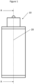
- Figure 1 is an external view a first LEM operating as an actuator 10 having a motion axis 20 along which a translator (shown later) moves and the locations of various planes for further sectional views.
- FIG. 2 shows the actuator 10 having a housing body 11.
- the housing body 11 is formed from a typically cylindrical wall 12 and by end walls 13 defining a hollow interior.
- the interior holds a stator 14, typically a tubular linear electrical machine stator, which has a cylindrical bore 15 extending axially from one end 16 of the stator to the other end 17.
- the housing body and the stator define a working cylinder 53.
- a central core 34 is fixed at least axially relative to the stator 14 within the working cylinder and, in this arrangement, is fixed at a central core fixing point 40 to the end wall 13.
- the upper end of the central core 34 is surrounded by a hollow translator 18, such that the translator slides over and outside the central core 34.
- the central core 34 and the stator define a stator bore cavity 51 therebetween.
- the stator bore cavity is a cylindrical annular space within which the translator 18 is axially movable relative to the stator 14.
- An exterior magnetic circuit airgap 21 exists between the translator and stator.
- the housing and therefore the stator are rigidly held and the translator 18 moves within the stator 14 and over the central core.
- a single elongate internal fluid bearing 35 is mounted on the central core and, in this example, no exterior fluid bearing is provided in the housing body 11.
- the fluid bearing is substantially the same length as the stator 14 so that any side loads generated by the electrical machine are matched by an opposing force applied by the fluid bearing in the same axial position.
- the bearing may be replaced by, or supplemented with, one or more flexures 52, shown in Figure 16 .
- This is particularly relevant in applications where the translator movement is small, typically less than 2mm.
- Such applications may include, but are not limited to systems that apply a short motive input such as in vehicle suspension systems to control ride dynamics.
- the flexure may take the form of a plate spring, leaf spring, diaphragm or other elastic or flexible element between the central core and the translator, and may or may not have axial holes or gaps. Further examples of flexures are shown in US 5522214 . In either example, the flexure or the fluid bearing constrain the radial motion of the translator and provide coaxial location of the translator within the stator bore cavity.
- a chamber housing 28 defines a preload chamber 29.
- the chamber housing is within the housing body and retained by end wall 13.
- the chamber housing could form the end wall and does not necessarily have to be within the housing body 11.
- An opening 30 into the preload chamber is closed by an end 19a of the translator. In this way, the sliding movement of the translator alters the volume of the preload chamber.
- the preload chamber is also provided with at least one conduit 47a through which pressurised fluid can be supplied to provide the necessary force onto the translator.
- the chamber 29 contains a fluid which is typically a gas (although a liquid is also possible) supplied at an elevated pressure and which applies a net force on the translator 18 in order to balance the test subject weight and/or to ensure the test subject is in the correct position prior to testing starting.
- an equivalent preload chamber function may be performed by chamber 50 formed between the upper end of the central core 34 and the translator 18.
- the sliding movement of the translator 18 within the cylindrical stator bore 15 changes the volume of preload chamber 29 and so creates the same effect as a piston moving within a cylinder.
- the working fluid in the preload chamber 29 is preferably a compressible gas, however this fluid could also be an incompressible liquid such as a hydraulic fluid which would be displaced through conduit 47a by the motion of the translator 18.
- This arrangement leads to improved test subject input signal quality when compared to airbag type preload force systems in which the translator motion and associated gas volume change is accommodated by the changing shape of a compliant element, whose compliance may result in unwanted system behaviour such as resonance or damping.
- the preload chamber is formed by a side wall 29a, which may or may not be a cylindrical wall, a first end wall 29b typically formed by an inner surface of the end wall 13 or the housing 12 and which is fixed with respect to the side wall 29a, the translator 18 and also by the outer surface of the central core 34.
- the chamber 29 is therefore generally annular.
- the preload chamber may not be a fully closed volume, and in addition to conduit 47a other small gaps may exist between the translator 18, the central core 34 and the chamber housing 28.
- any such gaps are considered as integral parts of surfaces 29a, 29b and 19a.
- One or more seals for example polymer gas seals, may be provided in this, or any other of the examples, to prevent significant leakage of the pressurised fluid from the preload chamber through such gaps.
- the volume of the preload chamber 29 is varied by movement of the translator.
- the first end wall 29b could also include a movable element which can vary the volume of the preload chamber together with the translator. Such a construction is less preferably due to the more complex control that would be required.
- a further wall element may be mounted on the translator 18, to act as the movable part of the second end wall. In this way, the translator itself may not define part of the preload chamber, but an additional element movable with the translator does.
- the preload chamber may have a uniform cross section along the axis 20.
- the upper end 19b of the translator 18 extends out of the upper end of the actuator 10 and is provided with a anchor point 33.
- the anchor point may be used for a test subject.
- the anchor point could be a flat plate or other surface onto which a test subject is positioned and held in place under its own weight, e.g. a vehicle resting on its tyres, each tyre positioned in contact with a test actuator.
- the anchor point could include one or more fixing means for securely fastening the translator to a test subject or part of an external system to which an input is applied. This may include one or more holes through the end of the translator.
- an encoder body 32 is located on the central core and allows the encoder scale 31, mounted on the inner part of the upper end of the hollow translator 18, to remain within the actuator.
- the encoder is a position encoder and the encoder scale is a shaft, but the encoder scale could also be a flat surface and the encoder type could also be a speed/velocity encoder.
- the encoder body 32 is located within the upper end of the central core 34, but may be located anywhere suitable and provides information concerning the position and or speed/velocity of the translator to ensure the actuator can be controlled.
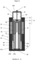
- FIG 3 is an external view of a linear electrical machine (LEM) 60, which could be operated as a generator having a motion axis 20 along which a translator (shown later) moves and the locations of planes BB and CC for further sectional views.
- LEM linear electrical machine
- FIG. 4 shows a cross sectional view of the LEM 60.
- the LEM 60 is identical to the actuator 10, except the addition of a working chamber 42 at the upper end, i.e. the opposite end to the preload chamber 29, the removal of the test subject mounting point 33 and the addition of a conduit 47b allowing fluid communication into and out of the working chamber 42.
- the working chamber could be a combustion chamber of an internal combustion engine, an expansion chamber for expansion of a high-pressure gas or two phase mixture to generate electrical power, a compression chamber for pressurising a gas or two phase mixture using electrical power, or a hydraulic chamber for receiving and displacing a hydraulic fluid or other liquid.
- the working chamber can act on the translator 18 to generate motion which then induces an electric current in the coils of the stator 14.
- a preload chamber 29 is provided to apply a controlled force to the translator 18 and acting to oppose or balance any force that may be applied to the translator by the working fluid in the working chamber.
- This function of the preload chamber 29 is to store translator energy that has not been recovered by the electrical machine when acting as a generator during the translator's downward stroke away from its 'top dead centre position' (i.e. the uppermost extent of its movement within the working chamber 42). After the translator has reached its bottom dead centre position the return of this energy to the translator 18, achieved as a result of the preload chamber applying a force on the translator during its upward stroke away from bottom dead centre, permits the linear electrical machine to continue acting as a generator on the return stroke back towards top dead centre.
- the pressure of the fluid within preload chamber 29 may be controlled by means of a preload chamber conduit 47a, which in addition may permit the preload working fluid to be displaced to and from the preload chamber as the volume of the preload chamber varies with the motion of the translator 18.
- the preload chamber 29 may be filled with the same fluid that is used in the working chamber 42 (for example, a rankine cycle fluid in the case of a rankine cycle gas expander application).
- the preload chamber 29 may be filled with another fluid selected according to the requirements of the application, which may be a gas, a liquid or a two phase mixture.
- the preload chamber may act as a bounce chamber, in which the pressure of the working fluid gas rises as the preload chamber volume reduces, resulting in a peak preload chamber force at or around a 'bottom dead centre' translator position shown in figure 7 .
- This bounce chamber function of the preload chamber serves to reduce the time taken for the translator to stop and change direction at the bottom of the stroke, thereby increasing the operating frequency and power density of a free piston engine, gas expander or other device utilising a working chamber and preload chamber.
- Figure 5 shows an alternative bearing configuration in which both an interior fluid bearing 35a and an exterior fluid bearing 22a are provided. Multiple exterior or interior fluid bearings could be provided if required.
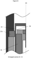
- Figures 6 and 7 illustrate the motion of the hollow translator 18 irrespective of the fluid bearing configuration, between the top of the stroke or 'top dead centre' position in Figure 6 to the bottom of the stroke or 'bottom dead centre' position in Figure 7 .
- the lower end of the translator 18 is substantially adjacent the lower end of the stator 14 and in this position the volume of the preload chamber 29 is at its maximum, and the volume of the working chamber 42 is at its minimum.
- the internal fluid bearing 35 there is no requirement for additional translator length beyond the lower end of the stator 17 in order to remain engaged with an external fluid bearing as might otherwise be required beneath the lower end of the stator 17, and the mass of the translator 18 is thereby substantially reduced for the same electromagnetic force.
- the upper end of the translator 18 is slightly above the level of the upper fluid bearing 22a, although in practice, the upper end may protrude further, or even be level with the upper end of the fluid bearing 22a.
- Figure 8 also illustrates the location of an exterior journal 23 on the translator. This is the surface onto which any external fluid bearing 22a acts.
- An internal journal surface 36 is also shown and is the surface onto which any internal fluid bearing 35 acts. The journal surfaces are typically machined onto the appropriate locations on the translator and therefore do not require additional elements to be joined to the translator for this purpose, and would not typically be provided unless a corresponding fluid bearing was used.
- the translator is kept in the coaxial position by the fluid bearing 35 which defines the interior bearing gap 37 between the outer surface of the fluid bearing 35 and one or more journals 36 on the interior surface of the translator. If one or more external fluid bearings 22a are also provided, the bearing gap between the inner surface of any external fluid bearing 22a and the outer surface of the translator and the magnetic circuit airgap 21 may be continuous.
- the relative sizes of any bearing gap and any magnetic circuit airgap are dependent upon the sizes of the translator, stator and fluid bearings.
- the bearing gap is typically smaller than the magnetic circuit airgap so that the magnetic circuit air gap thickness is more effectively controlled by the high radial stiffness of the fluid bearing.
- any of the fluid bearings could take the form as shown in Figure 10 in which the fluid bearing is formed from a plurality of fluid bearing shoes 44 spaced around (for exterior bearings) or inside (for interior bearings) the journal surface on which the bearing acts. Whilst two bearing shoes 44 are shown, three or four bearing shoes would be possible, and indeed a greater number would also be possible depending upon the size of the actuator and the loads which the bearing shoes experience.
- the bearing shoes are preferably spaced equally so as to provide even loading onto the translator and maintain the coaxial positioning of the translator relative to the stator.
- the fluid bearings could be formed from a generally porous material such as carbon. Alternatively the fluid bearing porosity could also be provided through an array of discrete holes machined within one or more solid bearing or bearing shoe components.
- Figure 11 illustrates that the interior fluid bearing (either with or without exterior fluid bearings), could alternatively be formed by two or more fluid bearings.
- the interior fluid bearing is replaced by an upper interior fluid bearing 35a and a lower interior fluid bearing 35b, and in addition an exterior fluid bearing 22a is also shown at the top of the stator.
- the splitting of the interior fluid bearing permits the axial space between to be utilised, in this case by the inclusion of an interior stator 38 mounted on the central core 34 to provide a greater electrical machine force per unit of translator moving mass. This significantly increases the dynamic performance of the actuator or LEM device acting on a working chamber.
- the interior stator 38 could be used in many different arrangements, for example with an upper interior fluid bearing and a lower exterior fluid bearing (or vice versa) and is not limited to the specific arrangement shown in Figure 11 .
- Figure 12 shows that the preload chamber 29 does not need to be a uniform shape, nor does the preload chamber itself need to be coaxial with the rest of the actuator.
- the asymmetric offset to the preload chamber 29 could be utilised in any of the arrangements in previous figures and may result in the preload chamber having a non-uniform cross section and/or a non-cylindrical side wall.
- Figure 13 shows a further alternative configuration in which a further internal fluid bearing 25 is provided in the translator 18 itself.
- the translator bearing 25 is mounted on the translator and movable with the translator.
- a further bearing journal surface 48 is formed on the inner surface of the working chamber 42 and a bearing gap is formed between the journal surface 48 and the translator bearing 25.
- Figure 14 illustrates a labyrinth seal 46 in which the flow of fluid and the difference in pressure between the working chamber 42 and the fluid bearing 35 is controlled by provision of a series of annular channels 46a in the translator,
- a labyrinth seal is a non-contact seal that is commonly used in piston expander and compressor applications.
- the use of a labyrinth seal in the present invention eliminates the friction that would otherwise be associated with a contact seal, and also removes the requirement for a separate vent between the fluid bearing and the working chamber.
- Figure 15 shows a further variant in which the central core 34 extends all the way through the translator 18, such that the translator is a hollow tube and is not closed at either end.
- the central core is fixed by fixing points 40 at both ends to the housing in order to maintain its radial position and axial within the LEM.
- the translator will, in use, slide up and down the central core.
- This arrangement provides a more secure fixing for the central core to reduce the extent of cantilever bending of the central core that might otherwise result in non-concentricity between the translator 19 and the stator 14.
- This arrangement permits the working chamber 42 and the preload chamber 29 to be equivalent in size and section area so that the preload chamber 29 could alternatively serve as a second working chamber.
- this arrangement reduces the area of the working chamber 42 that acts on the piston, and is therefore advantageous for high pressure working fluid applications.
- the force that applied by the working chamber pressure on end of the translator may otherwise exceed the capacity of the linear electrical machine and preload chamber to absorb the work applied by the working chamber over the course of a single stroke. Any of the previous bearing arrangements could be utilised in this variant.
Landscapes
- Engineering & Computer Science (AREA)
- Power Engineering (AREA)
- Physics & Mathematics (AREA)
- General Physics & Mathematics (AREA)
- Electromagnetism (AREA)
- Chemical & Material Sciences (AREA)
- Combustion & Propulsion (AREA)
- General Engineering & Computer Science (AREA)
- Mechanical Engineering (AREA)
- Microelectronics & Electronic Packaging (AREA)
- Connection Of Motors, Electrical Generators, Mechanical Devices, And The Like (AREA)
- Magnetic Bearings And Hydrostatic Bearings (AREA)
- Linear Motors (AREA)
- Reciprocating, Oscillating Or Vibrating Motors (AREA)
- Electromagnetic Pumps, Or The Like (AREA)
- Compressors, Vaccum Pumps And Other Relevant Systems (AREA)
Applications Claiming Priority (3)
| Application Number | Priority Date | Filing Date | Title |
|---|---|---|---|
| GB1701953.0A GB2558677A (en) | 2017-02-06 | 2017-02-06 | Linear electrical machine |
| EP18709718.3A EP3607292B1 (fr) | 2017-02-06 | 2018-02-01 | Machine électrique linéaire |
| PCT/GB2018/050290 WO2018142137A1 (fr) | 2017-02-06 | 2018-02-01 | Machine électrique linéaire |
Related Parent Applications (2)
| Application Number | Title | Priority Date | Filing Date |
|---|---|---|---|
| EP18709718.3A Division EP3607292B1 (fr) | 2017-02-06 | 2018-02-01 | Machine électrique linéaire |
| EP18709718.3A Division-Into EP3607292B1 (fr) | 2017-02-06 | 2018-02-01 | Machine électrique linéaire |
Publications (2)
| Publication Number | Publication Date |
|---|---|
| EP4236044A2 true EP4236044A2 (fr) | 2023-08-30 |
| EP4236044A3 EP4236044A3 (fr) | 2023-09-06 |
Family
ID=58462264
Family Applications (2)
| Application Number | Title | Priority Date | Filing Date |
|---|---|---|---|
| EP23163192.0A Pending EP4236044A3 (fr) | 2017-02-06 | 2018-02-01 | Machine électrique linéaire |
| EP18709718.3A Active EP3607292B1 (fr) | 2017-02-06 | 2018-02-01 | Machine électrique linéaire |
Family Applications After (1)
| Application Number | Title | Priority Date | Filing Date |
|---|---|---|---|
| EP18709718.3A Active EP3607292B1 (fr) | 2017-02-06 | 2018-02-01 | Machine électrique linéaire |
Country Status (7)
| Country | Link |
|---|---|
| US (1) | US11799360B2 (fr) |
| EP (2) | EP4236044A3 (fr) |
| JP (1) | JP7272955B2 (fr) |
| KR (1) | KR102571971B1 (fr) |
| CN (1) | CN110337582B (fr) |
| GB (1) | GB2558677A (fr) |
| WO (1) | WO2018142137A1 (fr) |
Families Citing this family (6)
| Publication number | Priority date | Publication date | Assignee | Title |
|---|---|---|---|---|
| CN109785982A (zh) * | 2018-12-07 | 2019-05-21 | 北京强度环境研究所 | 核反应堆石墨砖液体附加质量的试验装置及试验方法 |
| GB2574689B (en) | 2019-01-04 | 2020-07-15 | Libertine Fpe Ltd | Linear electrical machine |
| JP2022518045A (ja) | 2019-01-22 | 2022-03-11 | ウオーターズ・テクノロジーズ・コーポレイシヨン | リニアモーター |
| CN111677758A (zh) * | 2020-06-29 | 2020-09-18 | 杭州中奥工业设计有限公司 | 一种静压轴承 |
| CN111677757A (zh) * | 2020-06-29 | 2020-09-18 | 杭州中奥工业设计有限公司 | 一种可变油腔静压轴承 |
| KR102283940B1 (ko) * | 2021-05-28 | 2021-07-30 | 주식회사 호연 | 상하 슬라이드 유동에 기반한 모터검사장치 |
Citations (3)
| Publication number | Priority date | Publication date | Assignee | Title |
|---|---|---|---|---|
| US5522214A (en) | 1993-07-30 | 1996-06-04 | Stirling Technology Company | Flexure bearing support, with particular application to stirling machines |
| US7401520B2 (en) | 2005-08-26 | 2008-07-22 | Bose Corporation | Vehicle testing apparatus for applying vertical force to a wheel |
| US8844345B1 (en) | 2010-10-25 | 2014-09-30 | Roehrig Engineering, Inc. | Imparting motion to a test object such as a motor vehicle in a controlled fashion |
Family Cites Families (19)
| Publication number | Priority date | Publication date | Assignee | Title |
|---|---|---|---|---|
| JPS5952744U (ja) | 1982-09-29 | 1984-04-06 | 株式会社東芝 | 小形無線機 |
| US4675563A (en) | 1982-10-29 | 1987-06-23 | The United States Of America As Represented By The Administrator Of The National Aeronautics & Space Administration | Reciprocating linear motor |
| JPS59210575A (ja) * | 1983-05-13 | 1984-11-29 | Fujitsu Ltd | 磁気デイスク装置のヘツドアクセス機構 |
| JPH0479753A (ja) * | 1990-07-20 | 1992-03-13 | Toyoda Mach Works Ltd | 直動装置 |
| US5525845A (en) * | 1994-03-21 | 1996-06-11 | Sunpower, Inc. | Fluid bearing with compliant linkage for centering reciprocating bodies |
| US5952744A (en) * | 1996-03-28 | 1999-09-14 | Anoiad Corporation | Rotary-linear actuator |
| US5777403A (en) * | 1996-07-30 | 1998-07-07 | Nikon Corporation | Voice coil motor with air guide and air bellows |
| GB9721747D0 (en) * | 1997-10-15 | 1997-12-10 | Denne Phillip R M | Electromagnetic apparatus for producing linear motion |
| KR100304587B1 (ko) | 1999-08-19 | 2001-09-24 | 구자홍 | 리니어 압축기 |
| CN1175544C (zh) * | 2002-08-22 | 2004-11-10 | 哈尔滨工业大学 | 多气隙电机 |
| JP2004278475A (ja) | 2003-03-18 | 2004-10-07 | Matsushita Electric Ind Co Ltd | オイルレスリニア圧縮機 |
| JP2005009397A (ja) | 2003-06-19 | 2005-01-13 | Fuji Electric Holdings Co Ltd | 振動型圧縮機 |
| JP4603316B2 (ja) * | 2003-08-27 | 2010-12-22 | 山洋電気株式会社 | シリンダ型リニアモータ用可動子 |
| DE102005030161A1 (de) | 2005-06-29 | 2007-01-04 | Institut für Mikroelektronik und Mechatronik Systeme gGmbH | Vertikalantrieb mit Luftführung und Gewichtskompensation |
| JP4415133B2 (ja) * | 2008-02-07 | 2010-02-17 | 隆逸 小林 | リニア発電装置 |
| GB0902394D0 (en) * | 2009-02-13 | 2009-04-01 | Isis Innovation | Electric machine- cooling |
| JP5913910B2 (ja) * | 2011-04-26 | 2016-04-27 | 国際計測器株式会社 | 直動アクチュエータ及び加振装置 |
| HU229852B1 (en) * | 2012-08-15 | 2014-10-28 | Hibar Systems Ltd Richmond Hill | Electronically controlled and driven linear pump actuator |
| GB2574689B (en) * | 2019-01-04 | 2020-07-15 | Libertine Fpe Ltd | Linear electrical machine |
-
2017
- 2017-02-06 GB GB1701953.0A patent/GB2558677A/en not_active Withdrawn
-
2018
- 2018-02-01 EP EP23163192.0A patent/EP4236044A3/fr active Pending
- 2018-02-01 JP JP2019542527A patent/JP7272955B2/ja active Active
- 2018-02-01 CN CN201880010390.7A patent/CN110337582B/zh active Active
- 2018-02-01 EP EP18709718.3A patent/EP3607292B1/fr active Active
- 2018-02-01 US US16/483,649 patent/US11799360B2/en active Active
- 2018-02-01 WO PCT/GB2018/050290 patent/WO2018142137A1/fr active Application Filing
- 2018-02-01 KR KR1020197024873A patent/KR102571971B1/ko active IP Right Grant
Patent Citations (3)
| Publication number | Priority date | Publication date | Assignee | Title |
|---|---|---|---|---|
| US5522214A (en) | 1993-07-30 | 1996-06-04 | Stirling Technology Company | Flexure bearing support, with particular application to stirling machines |
| US7401520B2 (en) | 2005-08-26 | 2008-07-22 | Bose Corporation | Vehicle testing apparatus for applying vertical force to a wheel |
| US8844345B1 (en) | 2010-10-25 | 2014-09-30 | Roehrig Engineering, Inc. | Imparting motion to a test object such as a motor vehicle in a controlled fashion |
Also Published As
| Publication number | Publication date |
|---|---|
| KR20190116333A (ko) | 2019-10-14 |
| CN110337582B (zh) | 2021-10-29 |
| GB2558677A (en) | 2018-07-18 |
| JP2020508029A (ja) | 2020-03-12 |
| WO2018142137A1 (fr) | 2018-08-09 |
| CN110337582A (zh) | 2019-10-15 |
| KR102571971B1 (ko) | 2023-08-28 |
| US20190356200A1 (en) | 2019-11-21 |
| EP3607292C0 (fr) | 2023-07-19 |
| GB201701953D0 (en) | 2017-03-22 |
| EP3607292A1 (fr) | 2020-02-12 |
| JP7272955B2 (ja) | 2023-05-12 |
| EP3607292B1 (fr) | 2023-07-19 |
| BR112019015639A2 (pt) | 2020-03-31 |
| EP4236044A3 (fr) | 2023-09-06 |
| US11799360B2 (en) | 2023-10-24 |
Similar Documents
| Publication | Publication Date | Title |
|---|---|---|
| US11799360B2 (en) | Linear electrical machine | |
| US11467065B2 (en) | Hydro-magnetic linear actuator | |
| US20220085694A1 (en) | Linear electrical machine | |
| EP2253399A1 (fr) | Machine-outil et procédé de travail | |
| JP2005524064A (ja) | 高周波数の多自由度振動試験機械 | |
| JPS61144446A (ja) | ガススプリングを有する長寿命振動平衡機構 | |
| CN111152937A (zh) | 离心场中振动台动圈定中装置及定中方法 | |
| CN103062288A (zh) | 二维柔性铰链角度解耦的电磁阻尼零刚度隔振器 | |
| BR112019015639B1 (pt) | Máquina elétrica linear | |
| CN113898693B (zh) | 减振执行器 | |
| JP2001141599A (ja) | 振動/加振試験機 | |
| JP2003524763A (ja) | 柔軟なアクチュエータを備えた荷重アッセンブリ | |
| CN211685681U (zh) | 离心场中振动台动圈定中装置 | |
| CN109465650B (zh) | 气缸式刚度切换装置及使用其的刚柔耦合运动平台和方法 | |
| Heinken et al. | A high response electrorheological servo valve for active vibration decoupling | |
| RU146484U1 (ru) | Устройство для демпфирования колебаний | |
| CN117444259A (zh) | 一种主动式变刚度、变阻尼减振镗杆 | |
| JPH10339341A (ja) | ゴム部材のばね係数制御方法及び可変ばね機構 | |
| Li et al. | Study on Oil Pressure Characteristics and Trajectory Tracking Control in the Electro-hydraulic Servo System of a Torsional Isolator with Negative Stiffness Structures | |
| CN103047353A (zh) | 滚动关节轴承角度解耦的电涡流阻尼零刚度隔振器 | |
| CN111219443A (zh) | 一种基于磁流变弹性体的准零刚度隔振器 | |
| JPH05177486A (ja) | 主軸装置 | |
| JP2014055521A (ja) | ラビリンスピストン式往復動圧縮機 |
Legal Events
| Date | Code | Title | Description |
|---|---|---|---|
| PUAI | Public reference made under article 153(3) epc to a published international application that has entered the european phase |
Free format text: ORIGINAL CODE: 0009012 |
|
| STAA | Information on the status of an ep patent application or granted ep patent |
Free format text: STATUS: THE APPLICATION HAS BEEN PUBLISHED |
|
| REG | Reference to a national code |
Ref country code: DE Ref legal event code: R079 Free format text: PREVIOUS MAIN CLASS: H02K0041030000 Ipc: G01M0007000000 |
|
| PUAL | Search report despatched |
Free format text: ORIGINAL CODE: 0009013 |
|
| AC | Divisional application: reference to earlier application |
Ref document number: 3607292 Country of ref document: EP Kind code of ref document: P |
|
| AK | Designated contracting states |
Kind code of ref document: A2 Designated state(s): AL AT BE BG CH CY CZ DE DK EE ES FI FR GB GR HR HU IE IS IT LI LT LU LV MC MK MT NL NO PL PT RO RS SE SI SK SM TR |
|
| AK | Designated contracting states |
Kind code of ref document: A3 Designated state(s): AL AT BE BG CH CY CZ DE DK EE ES FI FR GB GR HR HU IE IS IT LI LT LU LV MC MK MT NL NO PL PT RO RS SE SI SK SM TR |
|
| RIC1 | Information provided on ipc code assigned before grant |
Ipc: H02K 5/167 20060101ALI20230801BHEP Ipc: H02K 5/20 20060101ALI20230801BHEP Ipc: H02K 41/03 20060101ALI20230801BHEP Ipc: G01M 17/04 20060101ALI20230801BHEP Ipc: G01M 17/007 20060101ALI20230801BHEP Ipc: G01M 7/02 20060101ALI20230801BHEP Ipc: G01M 17/00 20060101ALI20230801BHEP Ipc: G01M 7/00 20060101AFI20230801BHEP |
|
| STAA | Information on the status of an ep patent application or granted ep patent |
Free format text: STATUS: REQUEST FOR EXAMINATION WAS MADE |
|
| 17P | Request for examination filed |
Effective date: 20240305 |
|
| RBV | Designated contracting states (corrected) |
Designated state(s): AL AT BE BG CH CY CZ DE DK EE ES FI FR GB GR HR HU IE IS IT LI LT LU LV MC MK MT NL NO PL PT RO RS SE SI SK SM TR |