EP4236017A1 - Batteriestromausgleichsschaltung und -verfahren und energiespeichersystem - Google Patents
Batteriestromausgleichsschaltung und -verfahren und energiespeichersystem Download PDFInfo
- Publication number
- EP4236017A1 EP4236017A1 EP23158606.6A EP23158606A EP4236017A1 EP 4236017 A1 EP4236017 A1 EP 4236017A1 EP 23158606 A EP23158606 A EP 23158606A EP 4236017 A1 EP4236017 A1 EP 4236017A1
- Authority
- EP
- European Patent Office
- Prior art keywords
- battery
- control
- unit
- balancing
- target battery
- Prior art date
- Legal status (The legal status is an assumption and is not a legal conclusion. Google has not performed a legal analysis and makes no representation as to the accuracy of the status listed.)
- Pending
Links
Images



Classifications
-
- H—ELECTRICITY
- H02—GENERATION; CONVERSION OR DISTRIBUTION OF ELECTRIC POWER
- H02J—ELECTRIC POWER NETWORKS; CIRCUIT ARRANGEMENTS OR SYSTEMS FOR SUPPLYING OR DISTRIBUTING ELECTRIC POWER; SYSTEMS FOR STORING ELECTRIC ENERGY
- H02J7/00—Circuit arrangements for charging or discharging batteries or for supplying loads from batteries
- H02J7/50—Circuit arrangements for charging or discharging batteries or for supplying loads from batteries acting upon multiple batteries simultaneously or sequentially
- H02J7/52—Circuit arrangements for charging or discharging batteries or for supplying loads from batteries acting upon multiple batteries simultaneously or sequentially for charge balancing, e.g. equalisation of charge between batteries
- H02J7/56—Active balancing, e.g. using capacitor-based, inductor-based or DC-DC converters
-
- H—ELECTRICITY
- H02—GENERATION; CONVERSION OR DISTRIBUTION OF ELECTRIC POWER
- H02J—ELECTRIC POWER NETWORKS; CIRCUIT ARRANGEMENTS OR SYSTEMS FOR SUPPLYING OR DISTRIBUTING ELECTRIC POWER; SYSTEMS FOR STORING ELECTRIC ENERGY
- H02J15/00—Systems for storing electric energy specially adapted for power networks
-
- H—ELECTRICITY
- H02—GENERATION; CONVERSION OR DISTRIBUTION OF ELECTRIC POWER
- H02J—ELECTRIC POWER NETWORKS; CIRCUIT ARRANGEMENTS OR SYSTEMS FOR SUPPLYING OR DISTRIBUTING ELECTRIC POWER; SYSTEMS FOR STORING ELECTRIC ENERGY
- H02J3/00—Circuit arrangements for AC mains or AC distribution networks
- H02J3/28—Arrangements for balancing of the load in networks by storage of energy
- H02J3/32—Arrangements for balancing of the load in networks by storage of energy using batteries or super capacitors with converting means
-
- H—ELECTRICITY
- H02—GENERATION; CONVERSION OR DISTRIBUTION OF ELECTRIC POWER
- H02J—ELECTRIC POWER NETWORKS; CIRCUIT ARRANGEMENTS OR SYSTEMS FOR SUPPLYING OR DISTRIBUTING ELECTRIC POWER; SYSTEMS FOR STORING ELECTRIC ENERGY
- H02J7/00—Circuit arrangements for charging or discharging batteries or for supplying loads from batteries
- H02J7/80—Circuit arrangements for charging or discharging batteries or for supplying loads from batteries including monitoring or indicating arrangements
-
- H—ELECTRICITY
- H02—GENERATION; CONVERSION OR DISTRIBUTION OF ELECTRIC POWER
- H02J—ELECTRIC POWER NETWORKS; CIRCUIT ARRANGEMENTS OR SYSTEMS FOR SUPPLYING OR DISTRIBUTING ELECTRIC POWER; SYSTEMS FOR STORING ELECTRIC ENERGY
- H02J7/00—Circuit arrangements for charging or discharging batteries or for supplying loads from batteries
- H02J7/90—Regulation of charging or discharging current or voltage
- H02J7/96—Regulation of charging or discharging current or voltage in response to battery voltage
-
- B—PERFORMING OPERATIONS; TRANSPORTING
- B60—VEHICLES IN GENERAL
- B60L—PROPULSION OF ELECTRICALLY-PROPELLED VEHICLES; SUPPLYING ELECTRIC POWER FOR AUXILIARY EQUIPMENT OF ELECTRICALLY-PROPELLED VEHICLES; ELECTRODYNAMIC BRAKE SYSTEMS FOR VEHICLES IN GENERAL; MAGNETIC SUSPENSION OR LEVITATION FOR VEHICLES; MONITORING OPERATING VARIABLES OF ELECTRICALLY-PROPELLED VEHICLES; ELECTRIC SAFETY DEVICES FOR ELECTRICALLY-PROPELLED VEHICLES
- B60L58/00—Methods or circuit arrangements for monitoring or controlling batteries or fuel cells, specially adapted for electric vehicles
- B60L58/10—Methods or circuit arrangements for monitoring or controlling batteries or fuel cells, specially adapted for electric vehicles for monitoring or controlling batteries
- B60L58/18—Methods or circuit arrangements for monitoring or controlling batteries or fuel cells, specially adapted for electric vehicles for monitoring or controlling batteries of two or more battery modules
- B60L58/22—Balancing the charge of battery modules
-
- H—ELECTRICITY
- H01—ELECTRIC ELEMENTS
- H01M—PROCESSES OR MEANS, e.g. BATTERIES, FOR THE DIRECT CONVERSION OF CHEMICAL ENERGY INTO ELECTRICAL ENERGY
- H01M10/00—Secondary cells; Manufacture thereof
- H01M10/42—Methods or arrangements for servicing or maintenance of secondary cells or secondary half-cells
- H01M10/44—Methods for charging or discharging
- H01M10/441—Methods for charging or discharging for several batteries or cells simultaneously or sequentially
-
- H—ELECTRICITY
- H02—GENERATION; CONVERSION OR DISTRIBUTION OF ELECTRIC POWER
- H02J—ELECTRIC POWER NETWORKS; CIRCUIT ARRANGEMENTS OR SYSTEMS FOR SUPPLYING OR DISTRIBUTING ELECTRIC POWER; SYSTEMS FOR STORING ELECTRIC ENERGY
- H02J2207/00—Details of circuit arrangements for charging or discharging batteries or supplying loads from batteries
- H02J2207/20—Charging or discharging characterised by the power electronics converter
-
- H—ELECTRICITY
- H02—GENERATION; CONVERSION OR DISTRIBUTION OF ELECTRIC POWER
- H02J—ELECTRIC POWER NETWORKS; CIRCUIT ARRANGEMENTS OR SYSTEMS FOR SUPPLYING OR DISTRIBUTING ELECTRIC POWER; SYSTEMS FOR STORING ELECTRIC ENERGY
- H02J7/00—Circuit arrangements for charging or discharging batteries or for supplying loads from batteries
- H02J7/50—Circuit arrangements for charging or discharging batteries or for supplying loads from batteries acting upon multiple batteries simultaneously or sequentially
- H02J7/52—Circuit arrangements for charging or discharging batteries or for supplying loads from batteries acting upon multiple batteries simultaneously or sequentially for charge balancing, e.g. equalisation of charge between batteries
-
- H—ELECTRICITY
- H02—GENERATION; CONVERSION OR DISTRIBUTION OF ELECTRIC POWER
- H02J—ELECTRIC POWER NETWORKS; CIRCUIT ARRANGEMENTS OR SYSTEMS FOR SUPPLYING OR DISTRIBUTING ELECTRIC POWER; SYSTEMS FOR STORING ELECTRIC ENERGY
- H02J7/00—Circuit arrangements for charging or discharging batteries or for supplying loads from batteries
- H02J7/50—Circuit arrangements for charging or discharging batteries or for supplying loads from batteries acting upon multiple batteries simultaneously or sequentially
- H02J7/52—Circuit arrangements for charging or discharging batteries or for supplying loads from batteries acting upon multiple batteries simultaneously or sequentially for charge balancing, e.g. equalisation of charge between batteries
- H02J7/54—Passive balancing, e.g. using resistors or parallel MOSFETs
-
- Y—GENERAL TAGGING OF NEW TECHNOLOGICAL DEVELOPMENTS; GENERAL TAGGING OF CROSS-SECTIONAL TECHNOLOGIES SPANNING OVER SEVERAL SECTIONS OF THE IPC; TECHNICAL SUBJECTS COVERED BY FORMER USPC CROSS-REFERENCE ART COLLECTIONS [XRACs] AND DIGESTS
- Y02—TECHNOLOGIES OR APPLICATIONS FOR MITIGATION OR ADAPTATION AGAINST CLIMATE CHANGE
- Y02E—REDUCTION OF GREENHOUSE GAS [GHG] EMISSIONS, RELATED TO ENERGY GENERATION, TRANSMISSION OR DISTRIBUTION
- Y02E60/00—Enabling technologies; Technologies with a potential or indirect contribution to GHG emissions mitigation
- Y02E60/10—Energy storage using batteries
Definitions
- This application relates to the field of battery technologies, and in particular, to a battery electrical energy balancing circuit and method and an energy storage system.
- a passive balancing solution when a voltage is higher, a resistor is connected in series with an electrochemical cell with a higher voltage, and energy of the electrochemical cell is consumed by a resistor to achieve voltage balancing of the electrochemical cell.
- energy is transferred from a higher-voltage electrochemical cell to a lower-voltage electrochemical cell.
- a passive balancing circuit Compared with active balancing, a passive balancing circuit has a simple structure and low costs, and is easy to implement.
- disadvantages of the passive balancing are also obvious: The use of the resistor consumes energy, resulting in low energy utilization. Active balancing can transfer energy to avoid ineffective consumption of energy, but it is more complex to achieve active balancing, with more components used and higher costs consumed.
- Current active balancing solutions include capacitive energy transfer, inductive energy transfer, and transformer isolation.
- capacitive energy transfer a capacitor is used as an energy storage element, which can absorb energy of a high-voltage battery and transfer it to a low-voltage battery.
- inductive energy transfer an inductor is used as an energy storage element, which can transfer energy from a high-voltage electrochemical cell to a low-voltage electrochemical cell.
- the transformer isolation uses an isolation transformer to achieve bidirectional conversion of energy. When a voltage of an electrochemical cell is low, energy is supplied from a busbar to the electrochemical cell with a low voltage through a transformer. When a voltage of an electrochemical cell is high, energy flows from the electrochemical cell to the busbar through the transformer.
- the foregoing electrochemical cell active balancing topology circuits are all incompatible with an electrochemical cell sampling function, and an overall circuit structure of a battery management system (Battery Management System, BMS) is complex.
- BMS Battery Management System
- energy is fed back directly to a battery.
- the transformer still stores energy, causing a problem of continuous charging of the battery.
- a novel balancing circuit topology structure needs to be proposed, to reduce circuit complexity and costs while achieving efficient energy utilization.
- This application provides a battery electrical energy balancing circuit and method and an energy storage system, to reduce circuit complexity and costs while achieving efficient energy utilization.
- this application provides a battery electrical energy balancing circuit, applied to a series battery pack including N batteries connected in series.
- the circuit includes a controller, N battery control switches, a filter capacitor control unit, a balancing unit, and a sampling unit.
- Each battery in the N batteries is connected to a first end of each battery control switch in the N battery control switches in a one-to-one correspondence, and a second end of each battery control switch in the N battery control switches is connected to the filter capacitor control unit.
- the filter capacitor control unit is connected to the balancing unit and the sampling unit.
- the balancing unit is connected to a power supply, and the power supply is configured to supply power to the balancing unit.
- the balancing unit is configured to charge/discharge a target battery, where the target battery is any battery of the N batteries.
- the sampling unit is configured to detect a voltage of the target battery.
- the filter capacitor control unit is configured to filter a current input by the balancing unit to the target battery.
- the controller is configured to control a battery control switch connected to the target battery to be closed, to obtain a voltage value of the target battery detected by the sampling unit; or control the balancing unit to charge/discharge the target battery.
- the sampling unit and the balancing unit in the battery electrical energy balancing circuit in this application reuse N battery control switches, to not only achieve an active balancing function but also achieve a battery sampling function, which do not affect each other, thereby reducing complexity of a BMS used in a conventional solution.
- the power supply in this application is not directly connected to the battery, but instead, is charged indirectly through a transformer of the balancing unit, so that energy is fed back through an indirect feedback method, thereby resolving a problem of continuous charging when the battery is fully charged.
- the battery electrical energy balancing circuit further includes a first busbar and a second busbar
- the N batteries include a plurality of first batteries and a plurality of second batteries.
- the balancing unit includes a primary-side winding, a first secondary-side winding, a second secondary-side winding, and a first control switch.
- the sampling unit includes an analog to digital converter ADC and a sampling circuit. A second end of a battery control switch connected to the first battery is connected to the first busbar, and a second end of a battery control switch connected to the second battery is connected to the second busbar.
- the first busbar is connected to a first end of the filter capacitor control unit, and the second busbar is connected to a second end of the filter capacitor control unit.
- the first busbar is connected to the first secondary-side winding, and the second busbar is connected to the second secondary-side winding.
- the primary-side winding is connected to the power supply, and the primary-side winding is grounded through the first control switch.
- the first busbar is connected to a first input end of the sampling circuit, the second busbar is connected to a second input end of the sampling circuit, an output end of the sampling circuit is connected to the ADC, and an output end of the ADC is connected to the controller.
- the battery electrical energy balancing circuit in this application uses design of a single primary-side winding and double secondary-side windings. There are a plurality of switches for control between the battery control switches and the windings of the balancing unit, and only two switches are high-frequency switches for driving, thereby reducing a quantity of high-frequency switches for driving, so that a driving circuit in the controller is easier to implement and costs of high-frequency driving are reduced.
- the battery control switch in this application uses a paired MOS structure, to achieve bidirectional conduction.
- the controllable filter capacitor is introduced, so that the voltage sampling circuit and the balancing unit reuse the N battery control switches with a better effect. This not only achieves the active balancing function but also achieves the battery sampling function, thereby reducing complexity of a BMS used in a conventional solution.
- the filter capacitor control unit specifically includes a filter capacitor and a second control switch, the second control switch and the filter capacitor are connected in series.
- the controller is specifically configured to control the battery control switch connected to the target battery to be closed and control the second control switch to be open, to obtain the voltage value of the target battery detected by the sampling unit; or control the battery control switch connected to the target battery to be closed and control the second control switch to be closed, to control the balancing unit to charge/discharge the target battery.
- the controller is specifically configured to: when it is detected that a voltage difference between a first target battery and a second target battery is greater than a specified voltage threshold, where the first target battery and the second target battery are any two batteries in the series battery pack including the N batteries connected in series, and a voltage value of the first target battery is less than a voltage value of the second target battery, control a battery control switch connected to the first target battery to be closed, to charge the first target battery by using the balancing unit; and control a battery control switch connected to the second target battery to be closed, to discharge the second target battery by using the balancing unit.
- the controller may determine voltages of the batteries, and if it is determined that a difference between voltage of a battery and a voltage of another battery is greater than the specified voltage threshold, it is determined that undervoltage or overvoltage occurs in the battery. If undervoltage occurs in the battery, the balancing unit charges the battery; or if overvoltage occurs in the battery, the balancing unit charges the battery.
- the battery electrical energy balancing circuit may further include a current detection circuit and a temperature detection circuit, the current detection circuit is configured to detect a current value of each battery in the N batteries, and the temperature detection circuit is configured to detect a temperature value of each battery in the N batteries.
- the balancing unit further includes a first power tube, a second power tube, a third power tube, and a fourth power tube.
- a first end of the first power tube is connected to a dotted terminal of the first secondary-side winding, a second end of the first power tube is connected to the first busbar, a first end of the second power tube is connected to an undotted terminal of the first secondary-side winding, and a second end of the second power tube is connected to the second busbar.
- a first end of the third power tube is connected to an undotted terminal of the second secondary-side winding, a second end of the third power tube is connected to the first busbar, a first end of the fourth power tube is connected to a dotted terminal of the second secondary-side winding, and a second end of the fourth power tube is connected to the second busbar.
- the power supply is connected to a dotted terminal of the primary-side winding, and an undotted terminal of the primary-side winding is grounded through the first control switch.
- the transformer in the balancing unit uses design of a single primary-side winding and double secondary-side windings.
- switches for control between a busbar switch network bus and windings of the transformer where two switches are low-frequency signal switches for driving, and two switches are high-frequency signal switches for driving, thereby reducing a quantity of high-frequency switches for driving, so that a driving circuit in the controller is easy to implement and costs of high-frequency driving are reduced.
- the controller is specifically configured to: during charging of the battery, if a voltage of the first busbar is greater than a voltage of the second busbar, control the first power tube and the second power tube to be open and the third power tube to be closed, set the fourth power tube to a rectification state, and control the first control switch to be open, to release electrical energy stored in excitation inductance of the primary-side winding to the battery through the second secondary-side winding.
- a battery control switch in the N battery control switches that corresponds to a battery voltage is selected and is closed. When the battery voltage is relatively low, the battery is charged through a flyback converter by using the power supply or prestored electrical energy, to achieve charging balancing of the low-voltage battery. Electrical energy stored in the exciting inductance is released to the low-voltage battery through the second secondary-side winding.
- the controller is specifically configured to: during charging of the battery, if a voltage of the first busbar is less than a voltage of the second busbar, control the third power tube and the fourth power tube to be open and the second power tube to be closed, set the first power tube to a rectification state, and control the first control switch to be open, to release electrical energy stored in excitation inductance of the primary-side winding to the battery through the first secondary-side winding.
- the controller is specifically configured to: during discharging of the battery, if a voltage of the first busbar is greater than a voltage of the second busbar, control the third power tube and the fourth power tube to be open and the second power tube to be closed, set the first power tube to a rectification state, and control the first control switch to be closed, to store electrical energy in excitation inductance of the primary-side winding.
- a battery control switch in the N battery control switches that corresponds to a battery voltage is selected and is closed.
- the battery voltage is relatively high, electrical energy of the high-voltage battery is released through a flyback converter, to achieve charging balancing of the high-voltage battery. Electrical energy stored in the exciting inductance is released to the low-voltage battery through the second secondary-side winding.
- the controller is specifically configured to: during discharging of the battery, if a voltage of the first busbar is less than a voltage of the second busbar, control the first power tube and the second power tube to be open and the third power tube to be closed, set the first control switch to a rectification state, and control the fourth power tube to be closed, to store electrical energy in excitation inductance of the primary-side winding.
- each battery control switch in the N battery control switches is a paired MOS transistor
- the paired MOS transistor includes a first switch tube and a second switch tube.
- a source of the first switch tube is connected to a source of the second switch tube
- gates of the first switch tube and the second switch tube are connected to the controller
- a drain of the first switch tube is connected to the battery
- a drain of the second switch tube is connected to the corresponding first busbar and second busbar.
- this application provides a battery electrical energy balancing method.
- the method includes: controlling a battery control switch connected to a target battery to be closed, to obtain a voltage value of the target battery detected by a sampling unit; or controlling a balancing unit to charge/discharge the target battery.
- the method further includes: controlling the battery control switch connected to the target battery to be closed and controlling a second control switch to be open, to obtain the voltage value of the target battery detected by the sampling unit; or controlling the battery control switch connected to the target battery to be closed and controlling a second control switch to be closed, to control the balancing unit to charge/discharge the target battery.
- the controlling the second control switch to be closed and controlling closed/open states of N battery control switches to charge/discharge each battery in the N batteries by using the balancing unit includes: when it is detected that a voltage difference between a first target battery and a second target battery is greater than a specified voltage threshold, where the first target battery and the second target battery are any two batteries in the series battery pack including the N batteries connected in series, and a voltage value of the first target battery is less than a voltage value of the second target battery, control a battery control switch connected to the first target battery to be closed, to charge the first target battery by using the balancing unit; and control a battery control switch connected to the second target battery to be closed, to discharge the second target battery by using the balancing unit.
- this application provides an energy storage system, including: at least one energy storage unit and at least one conversion unit in a one-to-one correspondence with the at least one energy storage unit.
- Each conversion unit in the at least one conversion unit is connected to a power grid, and each energy storage unit in the at least one energy storage unit includes a series battery pack including N batteries connected in series and the battery electrical energy balancing circuit in the first aspect.
- Each energy storage unit in the at least one energy storage unit is configured to: output a direct current to a corresponding conversion unit, or receive a direct current input by a corresponding conversion unit and change the series battery pack including the N batteries connected in series.
- Each conversion unit in the at least one conversion unit is configured to: convert a direct current input by a corresponding energy storage unit into an alternating current and output it to the power grid; or receive an alternating current input by the power grid, convert the alternating current a direct current, and output it to a corresponding energy storage unit.
- connection in the embodiments of this application means an electrical connection, and a connection of two electrical components may be a direct or indirect connection between two electrical components.
- a connection between A and B may be either a direct connection between A and B, or an indirect connection between A and B through one or more other electrical components.
- the connection between A and B may be that A and C are directly connected, C and B are directly connected, and A and B are connected through C.
- dotted terminal and “undotted terminal” in this application are used to determine a phase relationship of an internal electromotive force between a primary-side winding and a secondary-side winding in a transformer when the transformer is operating. Under the action of a same magnetic flux, in two (or more than two) windings at any time, terminals with a same potential polarity are “dotted terminals” with respect to each other. Under the action of a same magnetic flux, in two (or more than two) windings at any time, terminals with opposite potential polarities are “undotted terminals" with respect to each other.
- a balancing circuit includes a gating switch and a bidirectional flyback converter including a plurality of power tubes.
- the foregoing structure is incompatible with a sampling function, and an overall circuit structure of a BMS used for sampling is complex.
- energy is fed back directly to a battery. When the battery is fully charged, the transformer still stores energy, causing a problem of continuous charging of the battery.
- a plurality of power tubes need to be driven by high-frequency signals. Therefore, a circuit for driving is also relatively complex, and a plurality of driving circuits need to be powered separately, causing relatively high circuit complexity and relatively high costs.
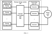
- FIG. 1 is a schematic diagram of a structure of an application scenario suitable for an embodiment of this application.
- an energy storage system 100 may be configured to store electrical energy.
- the energy storage system 100 may be charged by a power grid 101 or an external direct current source or an external alternating current source (not shown in FIG. 1 ).
- the energy storage system 100 may also generate an alternating current and provide the generated alternating current to the power grid 101 for power supply.
- the energy storage system 100 may include an energy storage module 102, a current converging unit 103, and a conversion unit 104.
- the energy storage module 102 may include a plurality of energy storage units, and the conversion unit 104 may include a plurality of inverters.
- the energy storage module 102 is configured to store energy, and output a current to the current converging unit 103 or receive a current from the current converging unit 103.
- the current converging unit 103 is configured to integrate a current provided by the energy storage module 102 or a current provided by the power grid 101.
- the conversion unit 104 is configured to convert a direct current provided by the energy storage module 102 into an alternating current, and input it to the power grid 101, or convert an alternating current provided by the power grid 101 into a direct current to charge the energy storage module 102.
- the energy storage system 100 in FIG. 1 is merely intended to describe the application scenario of this embodiment of this application but is not intended to limit this application.
- a connection relationship of a circuit is not limited in this embodiment of this application.
- another device may be connected between components in FIG. 1 .
- An output end of the conversion unit 104 may be connected directly to the power grid, or connected to the power grid through a transformer, which is not limited in this application.
- Each energy storage unit of the energy storage system 100 may include a battery electrical energy balancing circuit provided in this application.
- the conversion unit 104 includes but is not limited to: a direct current to direct current (direct current to direct current, DCDC) converter or a power storage converter (power conversion system, PCS).
- DCDC direct current to direct current
- PCS power storage converter
- the conversion unit 104 may be isolated, or may be non-isolated.
- FIG. 2 is a schematic diagram of a structure of a battery electrical energy balancing circuit 200.
- the circuit is applied to a series battery pack 201 including N batteries connected in series.
- the circuit includes a controller 202, N battery control switches 203, a filter capacitor control unit 204, a balancing unit 205, and a sampling unit 206.
- Each battery in the N batteries is connected to a first end of each battery control switch in the N battery control switches 203 in a one-to-one correspondence, and a second end of each battery control switch in the N battery control switches 203 is connected to the filter capacitor control unit 204.
- the filter capacitor control unit 204 is connected to the balancing unit 205 and the sampling unit 206.
- the balancing unit 205 is connected to a power supply 207, and the power supply 207 is configured to supply power to the balancing unit 205.
- the balancing unit 205 is configured to charge/discharge a target battery, where the target battery is any battery of the N batteries.
- the sampling unit 206 is configured to detect a voltage of the target battery.
- the filter capacitor control unit 204 is configured to filter a current input by the balancing unit 205 to the target battery.
- the controller 202 is configured to control a battery control switch 203 connected to the target battery to be closed, to obtain a voltage value of the target battery detected by the sampling unit 206; or control the balancing unit 205 to charge/discharge the target battery.
- the power supply 207 may be an external direct current source or an external alternating current source, or an energy storage battery, which is not specifically limited herein.
- the controller 202 in this embodiment of this application may be a central processing unit (central processing unit, CPU), a general-purpose processor, digital signal processing (digital signal processing, DSP), an application-specific integrated circuit (application-specific integrated circuit, ASIC), a field programmable gate array (field programmable gate array, FPGA), or another programmable logic device, a transistor logic device, a hardware component, or any combination thereof.
- the controller 202 may implement or execute logical blocks, modules, and circuits in various examples described with reference to content disclosed in this application.
- the processor may be a combination of processors implementing a computing function, for example, a combination of one or more microprocessors, or a combination of a DSP and a microprocessor.
- the controller 202 may be independent of the battery electrical energy balancing circuit 200, or may be integrated in another unit, which is not specifically limited herein.
- the controller 202 may also include a battery management system BMS, and the BMS is configured to detect battery parameters of the series battery pack 201 including the N batteries connected in series, to prevent the series battery pack 201 including the N batteries connected in series from being overcharged or overdischarged or the like, so as to prolong service life of each battery in the series battery pack 201 including the N batteries connected in series.
- BMS battery management system
- the BMS detects whether an arc fault occurs at each electrical connection point, and takes a corresponding protective measure.
- the balancing unit 205 in this embodiment of this application may be a direct current converter.
- the controller 202 may control the balancing unit 205 based on a preset battery balancing algorithm to perform balancing control on a battery requiring balancing.
- the controller 202 charges/discharges each battery in the series battery pack 201 by controlling the balancing unit, to achieve SOC balancing, and a corresponding charge/discharge current may be transferred by using a positive balancing busbar and a negative balancing busbar added in the balancing unit 205.
- the sampling unit 206 in this embodiment of this application may collect a battery parameter of each battery in the N batteries connected in series, where the battery parameter includes at least a voltage parameter, and sends the voltage parameter of each battery to the controller 202.
- the controller 202 determines whether each battery in the N batteries is abnormal based on the voltage parameter of each battery.
- the sampling unit 206 collects the voltage of each battery in the N batteries, to achieve detection on the voltage of each battery in the battery pack.
- the battery parameter may further include a temperature and a current.
- the battery electrical energy balancing circuit 200 may further include a current detection circuit and a temperature detection circuit, the current detection circuit is configured to detect a current value of each battery in the N batteries, and the temperature detection circuit is configured to detect a temperature value of each battery in the N batteries.
- the sampling unit 206 may continuously sample, a plurality of times, each battery in the series battery pack including the N batteries connected in series, and when sampling values consecutively sampled a plurality of times are basically the same, the sampling value is taken, so as to improve precision of the sampling voltage of the battery while reducing errors.
- the filter capacitor control unit 204 in this embodiment of this application may include a filter capacitor, to filter a current input by the balancing unit 205 to the target battery, and filter out a pulsating ripple caused by the power supply 207, thereby achieving an effect of a smooth current.
- the filter capacitor control unit 204 may further include a control switch, to control whether to connect the filter capacitor C 0 to the circuit by switching on/off a switch, so as to prevent the excessively large filter capacitor C 0 from affecting sampling of the sampling unit 206.
- the battery electrical energy balancing circuit 200 further includes a first busbar 208 and a second busbar 209, and the N batteries include a plurality of first batteries and a plurality of second batteries.
- the balancing unit 205 includes a primary-side winding 2051, a first secondary-side winding 2052, a second secondary-side winding 2053, and a first control switch 2054.
- the sampling unit 206 includes an analog to digital converter ADC 2061 and a sampling circuit 2062.
- a second end of a battery control switch 203 connected to the first battery is connected to the first busbar 208, and a second end of a battery control switch 203 connected to the second battery is connected to the second busbar 209.
- the first busbar 208 is connected to a first end of the filter capacitor control unit 204, and the second busbar 209 is connected to a second end of the filter capacitor control unit 204.
- the first busbar 208 is connected to the first secondary-side winding 2052, and the second busbar 209 is connected to the second secondary-side winding 2053.
- the primary-side winding 2051 is connected to the power supply 207, and the primary-side winding 2051 is grounded through the first control switch 2054.
- the first busbar 208 is connected to a first input end of the sampling circuit 2062
- the second busbar 209 is connected to a second input end of the sampling circuit 2062
- an output end of the sampling circuit 2062 is connected to the ADC 2061
- an output end of the ADC 2061 is connected to the controller 202.
- the controller 202 in this embodiment of this application controls the battery control switch 203 connected to the target battery to be closed, to obtain the voltage value of the target battery detected by the ADC 2061, where the target battery is any battery of the N batteries; or when performing balancing on the target battery, controls the balancing unit 205 to charge/discharge the target battery.
- the battery control switches 203 are connected to the first busbar 208 and the second busbar 209. When the battery control switches are successively closed (only one battery control switch is allowed to be closed at a time), a voltage of a positive electrode of a corresponding battery relative to a reference of the battery pack is applied to a bleeder resistor of the sampling circuit 2062. After being attenuated by the bleeder resistor, the voltage is sent to an analog to digital converter (analog to digital converter, ADC) for A/D conversion, to obtain a voltage value of the corresponding battery.
- ADC analog to digital converter
- the first busbar 208 and the second busbar 209 may jointly form an odd-even busbar. Specifically, in each battery in the series battery pack 201 including the N batteries connected in series, positive electrodes of all odd-numbered batteries are connected to each other and then are connected to the first busbar 208, and positive electrodes of all even-numbered batteries are connected to each other and then are connected to the second busbar 209. After all the even-numbered batteries are connected to each other, they are connected to a negative electrode of a 1 st battery of the series battery pack 201 including the N batteries connected in series.
- Fuses may be disposed on the first busbar 208 and the second busbar 209 to prevent a current on the busbar from being too large, so as to further improve safety of the battery electrical energy balancing circuit 200. Details are not described herein.
- the filter capacitor control unit 204 in this embodiment of this application may specifically include a filter capacitor C 0 and a second control switch, the second control switch and the filter capacitor are connected in series.
- the controller 202 is specifically configured to control the battery control switch connected to the target battery to be closed and control the second control switch to be open, to obtain the voltage value of the target battery detected by the sampling unit 206; or control the battery control switch connected to the target battery to be closed and control the second control switch to be closed, to control the balancing unit 205 to charge/discharge the target battery.
- the connection between the filter capacitor and the sampling unit 206 is disconnected by using the second control switch, to prevent an excessively large filter capacitor C 0 from affecting sampling precision of the sampling unit 206.
- the ADC 2061 in the sampling unit 206 is configured to convert an analog quantity input by the sampling circuit 2062 into a digital quantity.
- the sampling circuit 2062 in this embodiment of this application may include a bleeder resistor, to divide a voltage of a battery by using the bleeder resistor.
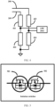
- the sampling circuit 2062 may include a first bleeder resistor 401, a second bleeder resistor 402, a third bleeder resistor 403, and a fourth bleeder resistor 404.
- Voltages output by the first busbar 208 and the second busbar 209 are divided by the first bleeder resistor 401, the second bleeder resistor 402, the third bleeder resistor 403, and the fourth bleeder resistor 404 and then sent to the ADC 2061 for sampling.
- FIG. 5 is a schematic diagram of a structure of a paired MOS transistor.
- the paired MOS transistor structure includes a first switch tube 501 and a second switch tube 502.
- the first switch tube 501 and the second switch tube 502 may be one or more types of switch devices such as metal oxide semiconductor field effect transistors (metal oxide semiconductor field effect transistor, MOSFET), bipolar junction transistors (bipolar junction transistor, BJT), insulated gate bipolar transistors (insulated gate bipolar transistor, IGBT), field effect transistors (field effect transistor, FET), and silicon carbide (SiC) or gallium nitride (GaN) power tubes, which are not listed one by one in this embodiment of this application.
- the switch tube may include a first electrode (source), a second electrode (drain), and a control electrode (gate).
- the controller 202 controls a switch device to be turned on or off by using the control electrode.
- the MOS transistor in this embodiment of this application is an N-channel metal oxide semiconductor (negative channel-metal-oxide-semiconductor, NMOS).
- the controller 202 may further include an auxiliary driving power supply and the like.
- a source of the first switch tube 501 is connected to a source of the second switch tube 502, gates of the first switch tube 501 and the second switch tube 502 are connected to the controller 202, a drain of the first switch tube 501 is connected to the battery, and a drain of the second switch tube 502 is connected to the corresponding first busbar 208 and second busbar 209.
- the ADC 2061 may collect a battery parameter of each battery in the N batteries connected in series, where the battery parameter includes at least a voltage parameter, and sends the voltage parameter of each battery to the controller 202.
- the controller 202 determines whether each battery in the N batteries is abnormal based on the voltage parameter of each battery.
- the sampling circuit 2062 collects the voltage of each battery in the N batteries, to achieve detection on the voltage of each battery in the battery pack.
- the battery parameter may further include a temperature and a current.
- the battery electrical energy balancing circuit 200 may further include a current detection circuit and a temperature detection circuit, the current detection circuit is configured to detect a current value of each battery in the N batteries, and the temperature detection circuit is configured to detect a temperature value of each battery in the N batteries.
- the battery electrical energy balancing circuit 200 may further include a current detection circuit and a temperature detection circuit, the current detection circuit is configured to detect a current value of each battery in the N batteries, and the temperature detection circuit is configured to detect a temperature value of each battery in the N batteries.
- the current detection circuit may include a current transformer (current transformer, CT), and the current transformer is an instrument that converts, based on a principle of electromagnetic induction, a large current on a primary side into a small current on a secondary side for measurement.
- the current transformer includes a closed core and windings. In a line with a current needing to be measured, the current transformer is sleeved on the first busbar 208 or the second busbar 209. Closure of the N battery control switches 203 is controlled by using a principle of electromagnetic mutual induction, to detect a current on the first busbar 208 or the second busbar 209, so as to determine a current parameter of the battery.
- a magnetic field is generated around a busbar to be measured, and after the current transformer is sleeved on a cable to be measured, a coil on the current transformer generates an induced current due to a magnetic field of the cable to be measured. After the induced current is amplified, a current of the cable to be measured may be obtained.
- the foregoing circuit may be utilized to detect a current and a temperature of each battery in the N batteries.
- the controller 202 controls the battery pack to stop charging or discharging in time, to protect the series battery pack 201 including the N batteries connected in series and prolong service life.
- the electrochemical cell is discharged or charged by using the balancing unit 205, to improve performance of the battery and safety of the series battery pack 201, and prolong the service life of the battery pack.
- the controller 202 is specifically configured to: when it is detected that a voltage difference between a first target battery and a second target battery is greater than a specified voltage threshold, where the first target battery and the second target battery are any two batteries in the series battery pack including the N batteries connected in series, and a voltage value of the first target battery is less than a voltage value of the second target battery, control a battery control switch connected to the first target battery to be closed, to charge the first target battery by using the balancing unit 205; and control a battery control switch connected to the second target battery to be closed, to discharge the second target battery by using the balancing unit 205.
- the controller 202 performs balancing control on to-be-balanced batteries according to a preset battery balancing algorithm based on voltage values of the batteries collected by the ADC 2061. Specifically, the controller may determine a voltage of each battery, and if it is determined that the voltage difference between the first target battery and the second target battery is greater than the specified voltage threshold, where the voltage value of the first target battery is less than the voltage value of the second target battery, undervoltage occurs in the first target battery, and the balancing unit 205 charges the battery; or overvoltage occurs in the second target battery, the balancing unit 205 discharges the battery.
- first target batteries or second target batteries when there are a plurality of first target batteries or second target batteries, they may be sorted based on voltages of the batteries, and balancing may be performed on the batteries based on an order obtained through sorting.
- a specific sorting manner is not specifically limited. For example, a battery with a lowest voltage is selected for charging from the plurality of batteries, and a battery with a highest voltage is selected for discharging from the plurality of batteries.
- the controller 202 may further determine a current of each battery in the N batteries, and if the current of the battery is greater than a rated current value, an overcurrent phenomenon occurs in the battery, and charging or discharging of the battery or a battery pack including the battery is stopped.
- the battery parameter may further include the temperature parameter
- the controller 202 may further determine a temperature of each battery in the N batteries or a temperature of the entire battery pack, and if a temperature of at least one battery in the N batteries the temperature of the entire battery pack is greater than a preset temperature value, it is determined that the battery or the battery pack is overheated, and charging or discharging of the battery or a battery pack including the battery is stopped. If the battery parameter includes at least two parameters of the voltage, the current, and the temperature, whether the battery is abnormal is comprehensively determined based on the battery parameter of each battery.
- the controller 202 determines the voltage of each battery. If it is determined that a voltage of a battery is less than the specified voltage value, a battery with a highest voltage may be obtained first from the series battery pack in which the battery is located, and a loop is established between the battery whose voltage is less than the specified voltage value and the battery with the highest voltage. The battery with the voltage less than the specified voltage value is charged by the battery with the highest voltage by using the loop until the battery with the voltage less than the specified voltage value reaches the specified voltage value.
- the balancing unit 205 further includes a first power tube 601, the second power tube 602, the third power tube 603, and the fourth power tube 604.
- a first end of the first power tube 601 is connected to a dotted terminal of the first secondary-side winding 2052, a second end of the first power tube 601 is connected to the first busbar 208, a first end of the second power tube 602 is connected to an undotted terminal of the first secondary-side winding 2052, and a second end of the second power tube 602 is connected to the second busbar 209.
- a first end of the third power tube 603 is connected to an undotted terminal of the second secondary-side winding 2053, a second end of the third power tube 603 is connected to the first busbar 208, a first end of the fourth power tube 604 is connected to a dotted terminal of the second secondary-side winding 2053, and a second end of the fourth power tube 604 is connected to the second busbar 209.
- the power supply is connected to a dotted terminal of the primary-side winding 2051, and an undotted terminal of the primary-side winding 2051 is grounded through the first control switch 2054.
- first control switch 2054 may also be a paired MOS tube, and the first power tube 601, the second power tube 602, the third power tube 603, and the fourth power tube 604 may be any one of the switch device types described in the foregoing embodiment.
- the transformer in the balancing unit 205 uses design of a single primary-side winding and double secondary-side windings. There are four switches for control between the busbar switch network bus and windings of the transformer, where two switches are low-frequency signal switches for driving, and two switches are high-frequency signal switches for driving, thereby reducing a quantity of high-frequency switches for driving, so that a driving circuit in the controller 202 is easy to implement and costs of high-frequency driving are reduced.
- controller 202 charges/discharges the battery by controlling disconnection of the first power tube 601, the second power tube 602, the third power tube 603, the fourth power tube 604, and the first control switch 2054, to achieve active balancing.
- Manner 1 During charging of the battery, if a voltage of the first busbar is greater than a voltage of the second busbar, controlling the first power tube and the second power tube to be open and the third power tube to be closed, setting the fourth power tube to a rectification state, and controlling the first control switch to be open, to release electrical energy stored in excitation inductance of the primary-side winding to the battery through the second secondary-side winding.
- a battery control switch in the N battery control switches 203 that corresponds to a battery voltage is selected and is closed.
- the battery voltage is relatively low, the battery is charged through a flyback converter by using the power supply or prestored electrical energy, to achieve charging balancing of the low-voltage battery. Electrical energy stored in the exciting inductance is released to the low-voltage battery through the second secondary-side winding.
- Manner 2 During charging of the battery, if a voltage of the first busbar is less than a voltage of the second busbar, controlling the third power tube and the fourth power tube to be open and the second power tube to be closed, setting the first power tube to a rectification state, and controlling the first control switch to be open, to release electrical energy stored in excitation inductance of the primary-side winding to the battery through the first secondary-side winding.
- Manner 3 During discharging of the battery, if a voltage of the first busbar is greater than a voltage of the second busbar, controlling the third power tube and the fourth power tube to be open and the second power tube to be closed, setting the first power tube to a rectification state, and controlling the first control switch to be closed, to store electrical energy in excitation inductance of the primary-side winding. Specifically, a battery control switch in the N battery control switches 203 that corresponds to a battery voltage is selected and is closed. When the battery voltage is relatively high, electrical energy of the high-voltage battery is released through a flyback converter, to achieve balancing of the high-voltage battery. Electrical energy stored in the exciting inductance is released to the low-voltage battery through the second secondary-side winding.
- Manner 4 During discharging of the battery, if a voltage of the first busbar is less than a voltage of the second busbar, controlling the first power tube and the second power tube to be open and the third power tube to be closed, setting the first control switch to a rectification state, and controlling the fourth power tube to be closed, to store electrical energy in excitation inductance of the primary-side winding.
- the controller 202 can control the balancing unit 205 to achieve balanced discharging of a high-voltage battery and balanced charging of a low-voltage battery by using a principle of the flyback converter.
- the battery electrical energy balancing circuit in this application uses design of a single primary-side winding and double secondary-side windings. There are a plurality of switches for control between the battery control switches and the windings of the balancing unit, and two switches are high-frequency switches for driving, thereby reducing a quantity of high-frequency switches for driving, so that a driving circuit in the controller is easier to implement and costs of high-frequency driving are reduced.
- the battery control switch in this application uses a paired MOS structure, to achieve bidirectional conduction.
- the controllable filter capacitor is introduced, so that the voltage sampling circuit and the balancing unit reuse the N battery control switches with a better effect.
- the power supply in this application is not directly connected to the battery, but instead, is charged indirectly through a transformer of the balancing unit, so that energy is fed back through an indirect feedback method, thereby resolving a problem of continuous charging when the battery is fully charged.
- this application further provides a battery electrical energy balancing method, applied to a battery electrical energy balancing circuit 200.
- the method includes: controlling a battery control switch connected to the target battery to be closed, to obtain a voltage value of the target battery detected by the sampling unit; or controlling the balancing unit to charge/discharge the target battery.
- the method further includes: controlling the battery control switch connected to the target battery to be closed and controlling a second control switch to be open, to obtain the voltage value of the target battery detected by the sampling unit; or controlling the battery control switch connected to the target battery to be closed and controlling a second control switch to be closed, to control the balancing unit to charge/discharge the target battery.
- the controlling the balancing unit to charge/discharge the target battery includes: when it is detected that a voltage difference between a first target battery and a second target battery is greater than a specified voltage threshold, where the first target battery and the second target battery are any two batteries in the series battery pack including the N batteries connected in series, and a voltage value of the first target battery is less than a voltage value of the second target battery, controlling a battery control switch connected to the first target battery to be closed, to control the balancing unit to charge the first target battery; and controlling a battery control switch connected to the second target battery to be closed, to control the balancing unit to discharge the second target battery.
- this application may be provided as a method, a system, or a computer program product. Therefore, this application may use a form of a hardware-only embodiment, a software-only embodiment, or an embodiment with a combination of software and hardware. In addition, this application may use a form of a computer program product that is implemented on one or more computer-usable storage media (including but not limited to a disk memory, a CD-ROM, an optical memory, and the like) that include computer-usable program code.
- a computer-usable storage media including but not limited to a disk memory, a CD-ROM, an optical memory, and the like
- the computer program instructions may be provided for a general-purpose computer, a dedicated computer, an embedded processor, or a processor of another programmable data processing device to generate a machine, so that the instructions executed by the computer or the processor of the another programmable data processing device generate an apparatus for implementing a specific function in one or more procedures in the flowcharts and/or in one or more blocks in the block diagrams.
- the computer program instructions may alternatively be stored in a computer-readable memory that can indicate a computer or another programmable data processing device to work in a specific manner, so that the instructions stored in the computer-readable memory generate an artifact that includes an instruction apparatus.
- the instruction apparatus implements a specific function in one or more procedures in the flowcharts and/or in one or more blocks in the block diagrams.
- the computer program instructions may alternatively be loaded onto a computer or another programmable data processing device, so that a series of operations and steps are performed on the computer or the another programmable device, so that computer-implemented processing is generated. Therefore, the instructions executed on the computer or the another programmable device provide steps for implementing a specific function in one or more procedures in the flowcharts and/or in one or more blocks in the block diagrams.
Landscapes
- Engineering & Computer Science (AREA)
- Power Engineering (AREA)
- Charge And Discharge Circuits For Batteries Or The Like (AREA)
Applications Claiming Priority (1)
| Application Number | Priority Date | Filing Date | Title |
|---|---|---|---|
| CN202210178430.7A CN114530910B (zh) | 2022-02-25 | 2022-02-25 | 一种电池电能均衡电路、方法以及储能系统 |
Publications (1)
| Publication Number | Publication Date |
|---|---|
| EP4236017A1 true EP4236017A1 (de) | 2023-08-30 |
Family
ID=81624675
Family Applications (1)
| Application Number | Title | Priority Date | Filing Date |
|---|---|---|---|
| EP23158606.6A Pending EP4236017A1 (de) | 2022-02-25 | 2023-02-24 | Batteriestromausgleichsschaltung und -verfahren und energiespeichersystem |
Country Status (3)
| Country | Link |
|---|---|
| US (1) | US20230275440A1 (de) |
| EP (1) | EP4236017A1 (de) |
| CN (1) | CN114530910B (de) |
Cited By (3)
| Publication number | Priority date | Publication date | Assignee | Title |
|---|---|---|---|---|
| CN119765588A (zh) * | 2025-03-06 | 2025-04-04 | 杭州元芯半导体科技有限公司 | 基于双向反激变换器的电池均衡电路及电池均衡控制方法 |
| EP4597788A1 (de) * | 2024-01-30 | 2025-08-06 | Huawei Digital Power Technologies Co., Ltd. | Batteriepack |
| CN120638542A (zh) * | 2025-06-05 | 2025-09-12 | 杭州晶华微电子股份有限公司 | 一种基于变压器的电池电压均衡电路及控制方法 |
Families Citing this family (10)
| Publication number | Priority date | Publication date | Assignee | Title |
|---|---|---|---|---|
| CN114530910B (zh) * | 2022-02-25 | 2026-03-27 | 华为数字能源技术有限公司 | 一种电池电能均衡电路、方法以及储能系统 |
| CN115021364A (zh) * | 2022-06-28 | 2022-09-06 | 龚晓军 | 一种电池的电能均衡电路及其均衡方法、储能系统 |
| CN115622200B (zh) * | 2022-12-13 | 2023-04-07 | 麦田能源有限公司 | 电池包的电压均衡方法、电池储能供电系统及电子装置 |
| CN115663978B (zh) * | 2022-12-13 | 2023-04-07 | 麦田能源有限公司 | 电池储能供电系统、电池包的电压均衡方法、装置 |
| CN116388321B (zh) * | 2023-02-15 | 2026-04-10 | 深圳市道通科技股份有限公司 | 电池放电电路、电路控制方法及电池放电装置 |
| CN116131417B (zh) * | 2023-04-19 | 2023-08-01 | 宁波均胜新能源研究院有限公司 | 均衡电路、均衡控制方法与充电机 |
| CN118232484B (zh) * | 2024-05-23 | 2024-08-27 | 西安图为电气技术有限公司 | 直流储能设备 |
| CN118739482B (zh) * | 2024-06-20 | 2025-10-10 | 广东新型储能国家研究院有限公司 | 储能系统的功率控制方法和装置 |
| CN118572842A (zh) * | 2024-08-02 | 2024-08-30 | 云储新能源科技有限公司 | 一种储能系统用高精度电池电压采集系统及方法 |
| CN119667272A (zh) * | 2024-12-10 | 2025-03-21 | 广州鸿博微电子技术有限公司 | 一种电池电压采集系统及其控制方法 |
Citations (5)
| Publication number | Priority date | Publication date | Assignee | Title |
|---|---|---|---|---|
| US20120086390A1 (en) * | 2009-01-30 | 2012-04-12 | Korea Advanced Institute Of Science And Technology | Charge Equalization Apparatus And Method For Series-Connected Battery String |
| KR101294378B1 (ko) * | 2011-02-22 | 2013-08-23 | 주식회사 에너닉스 | 배터리 셀 밸런싱 제어장치 및 이의 방법 |
| CN107658936A (zh) * | 2017-10-20 | 2018-02-02 | 广州金升阳科技有限公司 | 一种电池监测及均衡系统及其控制方法 |
| EP3691075B1 (de) * | 2019-01-30 | 2021-08-04 | Quanta Computer Inc. | Regler zum ausgleich von batteriesätzen und automatisches batterieausgleichssystem damit |
| CN114530910A (zh) * | 2022-02-25 | 2022-05-24 | 华为数字能源技术有限公司 | 一种电池电能均衡电路、方法以及储能系统 |
Family Cites Families (5)
| Publication number | Priority date | Publication date | Assignee | Title |
|---|---|---|---|---|
| CN102222957B (zh) * | 2011-06-21 | 2013-10-09 | 清华大学深圳研究生院 | 电池电量自动均衡电路及其实现方法 |
| US9225191B2 (en) * | 2013-02-19 | 2015-12-29 | Freescale Semiconductor, Inc. | Circuit and method for voltage equalization in large batteries |
| CN105789715A (zh) * | 2016-02-25 | 2016-07-20 | 上海大学 | 一种共用开关阵列的电池采样均衡电路 |
| CN107658935B (zh) * | 2017-10-20 | 2024-11-15 | 广州金升阳科技有限公司 | 一种电池监测及均衡系统及其控制方法 |
| CN112265473B (zh) * | 2020-10-19 | 2021-11-30 | 珠海格力电器股份有限公司 | 一种驱动装置 |
-
2022
- 2022-02-25 CN CN202210178430.7A patent/CN114530910B/zh active Active
-
2023
- 2023-02-22 US US18/172,548 patent/US20230275440A1/en active Pending
- 2023-02-24 EP EP23158606.6A patent/EP4236017A1/de active Pending
Patent Citations (5)
| Publication number | Priority date | Publication date | Assignee | Title |
|---|---|---|---|---|
| US20120086390A1 (en) * | 2009-01-30 | 2012-04-12 | Korea Advanced Institute Of Science And Technology | Charge Equalization Apparatus And Method For Series-Connected Battery String |
| KR101294378B1 (ko) * | 2011-02-22 | 2013-08-23 | 주식회사 에너닉스 | 배터리 셀 밸런싱 제어장치 및 이의 방법 |
| CN107658936A (zh) * | 2017-10-20 | 2018-02-02 | 广州金升阳科技有限公司 | 一种电池监测及均衡系统及其控制方法 |
| EP3691075B1 (de) * | 2019-01-30 | 2021-08-04 | Quanta Computer Inc. | Regler zum ausgleich von batteriesätzen und automatisches batterieausgleichssystem damit |
| CN114530910A (zh) * | 2022-02-25 | 2022-05-24 | 华为数字能源技术有限公司 | 一种电池电能均衡电路、方法以及储能系统 |
Cited By (3)
| Publication number | Priority date | Publication date | Assignee | Title |
|---|---|---|---|---|
| EP4597788A1 (de) * | 2024-01-30 | 2025-08-06 | Huawei Digital Power Technologies Co., Ltd. | Batteriepack |
| CN119765588A (zh) * | 2025-03-06 | 2025-04-04 | 杭州元芯半导体科技有限公司 | 基于双向反激变换器的电池均衡电路及电池均衡控制方法 |
| CN120638542A (zh) * | 2025-06-05 | 2025-09-12 | 杭州晶华微电子股份有限公司 | 一种基于变压器的电池电压均衡电路及控制方法 |
Also Published As
| Publication number | Publication date |
|---|---|
| CN114530910B (zh) | 2026-03-27 |
| US20230275440A1 (en) | 2023-08-31 |
| CN114530910A (zh) | 2022-05-24 |
Similar Documents
| Publication | Publication Date | Title |
|---|---|---|
| EP4236017A1 (de) | Batteriestromausgleichsschaltung und -verfahren und energiespeichersystem | |
| US7061207B2 (en) | Cell equalizing circuit | |
| TWI751229B (zh) | 控制裝置、控制系統、蓄電裝置以及電腦可讀取媒體 | |
| CN110126658B (zh) | 一种端口复用的双向充电机及其应用方法 | |
| EP2660947B1 (de) | Batteriemodul-aufladesystem | |
| US20090140693A1 (en) | Flyback charge redistribution apparatus for serially connected energy storage devices using flyback-type converters | |
| TWI857977B (zh) | 蓄電系統 | |
| CN103812153B (zh) | 新能源汽车用主动平衡式bms控制模块及其控制方法 | |
| JPH0919072A (ja) | 電気エネルギー蓄電池用の充電器 | |
| EP3420623B1 (de) | Batterievorrichtung und zellenausgleichsschaltungen | |
| CN112119562A (zh) | 蓄电系统 | |
| CN103229384A (zh) | 用于平衡蓄电池的电池单元的转换器 | |
| EP4113819B1 (de) | Schaltungsvermittlungsschaltkreis und steuerungsverfahren | |
| KR101720027B1 (ko) | 배터리 셀 전압 균등 제어장치 및 제어방법 | |
| US20240146073A1 (en) | Serial tapped inductor battery balancer | |
| JP2012100443A (ja) | 急速充電方法及び装置 | |
| JP2001268815A (ja) | 充電回路 | |
| TWI635691B (zh) | Battery pack active balancing system | |
| WO2022217721A1 (zh) | 智慧电池 | |
| CN200994071Y (zh) | 蓄电池充电器 | |
| CN220234235U (zh) | 电池管理系统以及电池系统 | |
| CN112217263B (zh) | 电池组均衡控制电路及电源芯片 | |
| CN116979640A (zh) | 电池管理系统以及电池系统 | |
| JP2015042013A (ja) | 充電装置 | |
| CN111509808A (zh) | 一种锂电池组电池管理系统及管理方法 |
Legal Events
| Date | Code | Title | Description |
|---|---|---|---|
| PUAI | Public reference made under article 153(3) epc to a published international application that has entered the european phase |
Free format text: ORIGINAL CODE: 0009012 |
|
| STAA | Information on the status of an ep patent application or granted ep patent |
Free format text: STATUS: THE APPLICATION HAS BEEN PUBLISHED |
|
| AK | Designated contracting states |
Kind code of ref document: A1 Designated state(s): AL AT BE BG CH CY CZ DE DK EE ES FI FR GB GR HR HU IE IS IT LI LT LU LV MC ME MK MT NL NO PL PT RO RS SE SI SK SM TR |
|
| STAA | Information on the status of an ep patent application or granted ep patent |
Free format text: STATUS: REQUEST FOR EXAMINATION WAS MADE |
|
| 17P | Request for examination filed |
Effective date: 20231130 |
|
| RBV | Designated contracting states (corrected) |
Designated state(s): AL AT BE BG CH CY CZ DE DK EE ES FI FR GB GR HR HU IE IS IT LI LT LU LV MC ME MK MT NL NO PL PT RO RS SE SI SK SM TR |
|
| STAA | Information on the status of an ep patent application or granted ep patent |
Free format text: STATUS: EXAMINATION IS IN PROGRESS |
|
| 17Q | First examination report despatched |
Effective date: 20250305 |
|
| REG | Reference to a national code |
Ref country code: DE Ref legal event code: R079 Free format text: PREVIOUS MAIN CLASS: H02J0007000000 Ipc: H02J0007560000 |
|
| GRAP | Despatch of communication of intention to grant a patent |
Free format text: ORIGINAL CODE: EPIDOSNIGR1 |
|
| STAA | Information on the status of an ep patent application or granted ep patent |
Free format text: STATUS: GRANT OF PATENT IS INTENDED |
|
| RIC1 | Information provided on ipc code assigned before grant |
Ipc: H02J 7/56 20260101AFI20260312BHEP Ipc: H02J 7/80 20260101ALI20260312BHEP |
|
| INTG | Intention to grant announced |
Effective date: 20260327 |