EP4235070A2 - Anlage zum trocknen von körnigem polymermaterial - Google Patents
Anlage zum trocknen von körnigem polymermaterial Download PDFInfo
- Publication number
- EP4235070A2 EP4235070A2 EP23184724.5A EP23184724A EP4235070A2 EP 4235070 A2 EP4235070 A2 EP 4235070A2 EP 23184724 A EP23184724 A EP 23184724A EP 4235070 A2 EP4235070 A2 EP 4235070A2
- Authority
- EP
- European Patent Office
- Prior art keywords
- process gas
- plant
- hopper
- condenser
- polymer material
- Prior art date
- Legal status (The legal status is an assumption and is not a legal conclusion. Google has not performed a legal analysis and makes no representation as to the accuracy of the status listed.)
- Granted
Links
Images

Classifications
-
- F—MECHANICAL ENGINEERING; LIGHTING; HEATING; WEAPONS; BLASTING
- F26—DRYING
- F26B—DRYING SOLID MATERIALS OR OBJECTS BY REMOVING LIQUID THEREFROM
- F26B3/00—Drying solid materials or objects by processes involving the application of heat
- F26B3/02—Drying solid materials or objects by processes involving the application of heat by convection, i.e. heat being conveyed from a heat source to the materials or objects to be dried by a gas or vapour, e.g. air
- F26B3/06—Drying solid materials or objects by processes involving the application of heat by convection, i.e. heat being conveyed from a heat source to the materials or objects to be dried by a gas or vapour, e.g. air the gas or vapour flowing through the materials or objects to be dried
-
- B—PERFORMING OPERATIONS; TRANSPORTING
- B29—WORKING OF PLASTICS; WORKING OF SUBSTANCES IN A PLASTIC STATE IN GENERAL
- B29B—PREPARATION OR PRETREATMENT OF THE MATERIAL TO BE SHAPED; MAKING GRANULES OR PREFORMS; RECOVERY OF PLASTICS OR OTHER CONSTITUENTS OF WASTE MATERIAL CONTAINING PLASTICS
- B29B13/00—Conditioning or physical treatment of the material to be shaped
- B29B13/06—Conditioning or physical treatment of the material to be shaped by drying
- B29B13/065—Conditioning or physical treatment of the material to be shaped by drying of powder or pellets
-
- B—PERFORMING OPERATIONS; TRANSPORTING
- B29—WORKING OF PLASTICS; WORKING OF SUBSTANCES IN A PLASTIC STATE IN GENERAL
- B29B—PREPARATION OR PRETREATMENT OF THE MATERIAL TO BE SHAPED; MAKING GRANULES OR PREFORMS; RECOVERY OF PLASTICS OR OTHER CONSTITUENTS OF WASTE MATERIAL CONTAINING PLASTICS
- B29B13/00—Conditioning or physical treatment of the material to be shaped
-
- F—MECHANICAL ENGINEERING; LIGHTING; HEATING; WEAPONS; BLASTING
- F26—DRYING
- F26B—DRYING SOLID MATERIALS OR OBJECTS BY REMOVING LIQUID THEREFROM
- F26B17/00—Machines or apparatus for drying materials in loose, plastic, or fluidised form, e.g. granules, staple fibres, with progressive movement
- F26B17/12—Machines or apparatus for drying materials in loose, plastic, or fluidised form, e.g. granules, staple fibres, with progressive movement with movement performed solely by gravity, i.e. the material moving through a substantially vertical drying enclosure, e.g. shaft
-
- F—MECHANICAL ENGINEERING; LIGHTING; HEATING; WEAPONS; BLASTING
- F26—DRYING
- F26B—DRYING SOLID MATERIALS OR OBJECTS BY REMOVING LIQUID THEREFROM
- F26B21/00—Arrangements for supplying or controlling air or other gases for drying solid materials or objects
- F26B21/30—Controlling, e.g. regulating, parameters of gas supply
- F26B21/33—Humidity
- F26B21/331—Humidity by using sorbent or hygroscopic materials, e.g. chemical substances or molecular sieves
-
- F—MECHANICAL ENGINEERING; LIGHTING; HEATING; WEAPONS; BLASTING
- F26—DRYING
- F26B—DRYING SOLID MATERIALS OR OBJECTS BY REMOVING LIQUID THEREFROM
- F26B25/00—Details of general application not covered by group F26B21/00 or F26B23/00
- F26B25/005—Treatment of dryer exhaust gases
- F26B25/006—Separating volatiles, e.g. recovering solvents from dryer exhaust gases
-
- B—PERFORMING OPERATIONS; TRANSPORTING
- B29—WORKING OF PLASTICS; WORKING OF SUBSTANCES IN A PLASTIC STATE IN GENERAL
- B29B—PREPARATION OR PRETREATMENT OF THE MATERIAL TO BE SHAPED; MAKING GRANULES OR PREFORMS; RECOVERY OF PLASTICS OR OTHER CONSTITUENTS OF WASTE MATERIAL CONTAINING PLASTICS
- B29B13/00—Conditioning or physical treatment of the material to be shaped
- B29B2013/005—Degassing undesirable residual components, e.g. gases, unreacted monomers, from material to be moulded
-
- B—PERFORMING OPERATIONS; TRANSPORTING
- B29—WORKING OF PLASTICS; WORKING OF SUBSTANCES IN A PLASTIC STATE IN GENERAL
- B29K—INDEXING SCHEME ASSOCIATED WITH SUBCLASSES B29B, B29C OR B29D, RELATING TO MOULDING MATERIALS OR TO MATERIALS FOR MOULDS, REINFORCEMENTS, FILLERS OR PREFORMED PARTS, e.g. INSERTS
- B29K2067/00—Use of polyesters or derivatives thereof, as moulding material
- B29K2067/003—PET, i.e. poylethylene terephthalate
-
- F—MECHANICAL ENGINEERING; LIGHTING; HEATING; WEAPONS; BLASTING
- F26—DRYING
- F26B—DRYING SOLID MATERIALS OR OBJECTS BY REMOVING LIQUID THEREFROM
- F26B2200/00—Drying processes and machines for solid materials characterised by the specific requirements of the drying goods
- F26B2200/08—Granular materials
Definitions
- the present invention relates to a plant for drying granular polymer material.
- the invention is particularly used in industrial processes for converting plastics material into granules by means of extrusion or moulding.
- plastics materials before being subjected to the extrusion or moulding process, have to be advantageously processed in suitable drying plants where the content of water of the granules is reduced to the minimal quantities required by the conversion process.
- the drying of the granular polymer material is carried out inside a hopper, in which the material to be dried is placed and in which there is introduced a continuous flow of a process gas which is hot and dry and which, by coming into contact with the granular material, provides for stripping the water present in the granules.
- the process gas which is typically air, before being introduced into the hopper in order to come into contact with the granular material to be dried, is dehumidified in a suitable dehumidification unit and is subsequently heated to the desired temperature.
- the process gas being discharged from the hopper is placed back into circulation in order to be dehumidified, heated and reintroduced into the hopper again.
- a main disadvantage of this prior art is that the resin loaded in the hopper and the process gas which is blown in through the resin contain some contaminating substances, such as, for example, residues of benzene and relevant derivatives, acetaldehyde (AA) and possible residual oils resulting from the recovery cycle of the recycled PET.
- some contaminating substances such as, for example, residues of benzene and relevant derivatives, acetaldehyde (AA) and possible residual oils resulting from the recovery cycle of the recycled PET.
- the problem addressed by the present invention is to provide a drying plant which is structurally and functionally configured to at least partially overcome one or more of the disadvantages set out above with reference to the cited prior art.
- an object of the present invention is to provide a drying plant which reduces the chemical impurities of the plastics materials with respect to a conventional drying plant as described above with reference to the prior art.
- An object of the present invention is also to provide a drying plant which reduces the overall emission of polluting substances with respect to a conventional drying plant as described above with reference to the prior art. Furthermore, an object of the present invention is to provide a drying plant which has a greater level of energy efficiency with respect to a conventional drying plant as described above with reference to the prior art.
- Another object of the invention is to provide a drying plant which is simple to construct and carry out.
- the invention is directed towards a plant for drying granular polymer material, comprising a hopper, in which the granular polymer material is dried, and a process gas circuit, which is configured to supply a process gas to the hopper in order to dry the granular polymer material.
- the process gas circuit comprises a dehumidification and heating unit which is configured to dehumidify and heat the process gas to predefined humidity and temperature values for supply to the hopper, respectively.
- the process gas circuit further comprises a purification group which is positioned at the outlet from the hopper and upstream of the dehumidification and heating unit and which is configured to purify the process gas from contaminating substances which are released by the granular polymer material in the hopper.
- the purification group comprises a condenser which is configured to cool the process gas to a predefined condensation temperature of the contaminating substances so as to separate from the process gas the contaminating substances condensed in this manner.
- the purification group further comprises a filter which is positioned at the outlet from the condenser and which contains activated carbon capable of absorbing any non-condensed contaminating substances.
- the purification group returns to the dehumidification and heating unit the process gas which is purified from the impurities which it accumulates during the passage of the hopper.
- the plant for drying granular polymer material constructed according to the present invention is particularly suitable for drying granular polymer material which contains rPET.
- the purification group for the process gas is particularly effective for reducing the chemical impurities such as benzene and relevant derivatives, acetaldehyde (AA) and possible residual oils resulting from the recovery cycle of the recycled PET.
- the condenser is configured to cool the process gas to a temperature between 10°C and 30°C, preferably to a temperature between 15°C and 25°C, even more preferably to a temperature of substantially 20°C. It will be appreciated that these temperature ranges advantageously correspond to the condensation point of benzene and/or acetaldehyde.
- the contaminating substances which are thereby condensed are conveyed through a discharge pipe towards a collection tank for the disposal thereof.
- the purification group comprises a first pipe for the process gas which is being discharged from the hopper and upstream of the condenser, and a second pipe for the process gas which is being discharged from the filter and upstream of the dehumidification and heating unit.
- the purification group further comprises a heat exchanger which preferably includes the first pipe and the second pipe.
- the heat exchanger is advantageously configured to exchange heat between the process gas being introduced into the purification group through the first pipe and the process gas being discharged from the purification group through the second pipe.
- the drying plant allows a better energy performance to be achieved.
- the first branch discharges heat to the second branch so as to cool the process gas before it reaches the condenser.
- the energy supply required for the condenser in order to reduce the temperature of the process gas to the predefined condensation temperature of the contaminating substances is reduced.
- the heat exchanger is further configured to cooperate with the condenser so as to cool the process gas to a suitable temperature for the dehumidification step.
- the Applicant has assessed, in an indicative manner, the efficiency of the purification group when the process gas being introduced into the purification group has the following characteristics: temperature of approximately 80°C, humidity of approximately 1000 parts per million (ppm), approximately 65 parts per billion (ppb) of benzene and approximately 1.2 ppm of acetaldehyde.
- the drying plant which is constructed according to the present invention achieves a purification of the process gas so as to obtain a process gas being discharged from the purification group with the following characteristics: temperature of approximately 60°C, humidity of approximately 1100 ppm, benzene less than 10 ppb and acetaldehyde less than 0.4 ppm.
- the process gas circuit comprises a movement unit which is configured to move the process gas along the process gas circuit, more specifically between the dehumidification and heating unit, the hopper and the purification group, and furthermore preferably in the purification group between the heat exchanger, the condenser and the filter.
- the process gas circuit further comprises a cyclone separator which is positioned at the outlet from the hopper and upstream of the purification group.
- the cyclone separator is preferably configured to separate the dust of the polymer material granules from the flow of process gas being introduced into the purification group.
- the cyclone By separating the dust from the process gas being introduced into the purification group, the cyclone prevents the dust from being able to obstruct the filter, inhibiting the action of the activated carbon. Therefore, the presence of the cyclone considerably extends the service-life of the filter and increases the absorption in the filter of the non-condensed contaminating substances.
- the presence of the cyclone further prevents the dust - being introduced into the condenser - from being able to become combined with the condensate, obstructing not only the filter but also the pipes themselves of the purification group. Therefore, the presence of the cyclone allows the entire purification group to be maintained at the correct functional efficiency. In the absence of the cyclone, furthermore, some of the dust could pass through the filter and could accumulate in the dehumidification and heating unit which is connected downstream. Therefore, the presence of the cyclone upstream also prevents this possible disadvantage.
- the movement unit (for example, an impeller fan) is connected downstream of the cyclone with respect to the direction of flow of process gas.
- the impeller of the fan or other components of the movement unit which are exposed to the flow of gas and which are therefore liable to become damaged in the presence of dust is/are also protected as a result of the action of the cyclone.
- the process gas circuit is a closed circuit with an inlet pipe into the hopper located downstream of the dehumidification and heating unit, an outlet pipe from the hopper located upstream of the purification group, and an inlet pipe into the dehumidification and heating unit located downstream of the purification group.
- a plant for drying granular polymer material which is constructed according to the present invention.
- the plant 1 is provided to dry any polymer material in granules, for example, polyamide, polycarbonate or ABS copolymer even if, in the preferred example described herein, the material processed is formed at a ratio of approximately 50% by granules of recycled polyethylene terephthalate (rPET).
- rPET recycled polyethylene terephthalate
- the plant 1 can be provided to supply a machine for converting the granular polymer material (not shown), such as, for example, a press or an extruder.
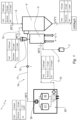
- the plant 1 comprises a loading line 4 which is provided to load the granular polymer material to be dried in the hopper 2.
- the plant 1 further comprises a process gas circuit 10 which is associated with the hopper 2 in order to introduce therein a hot and dry process gas which, by passing through the granular material contained in the hopper 2, is capable of reducing the degree of humidity thereof to the levels desired and suitable for the subsequent processing steps.
- a process gas circuit 10 which is associated with the hopper 2 in order to introduce therein a hot and dry process gas which, by passing through the granular material contained in the hopper 2, is capable of reducing the degree of humidity thereof to the levels desired and suitable for the subsequent processing steps.
- the process gas may be air or an inert gas without oxygen.
- the process gas circuit 10 includes a dehumidification and heating unit 20 comprising a heating device which is provided to heat the process gas to the predefined temperature for introduction into the hopper 2.
- a dehumidification and heating unit 20 comprising a heating device which is provided to heat the process gas to the predefined temperature for introduction into the hopper 2.
- the process gas is heated to approximately 90°.
- the dehumidification and heating unit 20 further comprises a pair of towers 21 and 22 which are mutually identical and which each contain a suitable quantity of drying compound, for example, zeolites.
- each tower 21, 22 has dimensions so as to dehumidify the process gas to a predefined humidity level, for example, corresponding to 20 parts per million (ppm) of water.
- a predefined humidity level for example, corresponding to 20 parts per million (ppm) of water.
- the towers 21 and 22 are connected to each other in parallel and are selectively and alternately able to be connected to the process gas circuit 10.
- the process gas circuit 10 further comprises a movement unit 30, preferably comprising one or more blowers, in order to move the process gas along the process gas circuit 10.
- an inlet pipe 11 Downstream of the dehumidification and heating unit 20, there is provided an inlet pipe 11, by means of which the process gas is introduced into the hopper 2. Along the inlet pipe 11 there can be provided a sampling location 12 for sampling the process gas. It is thereby possible to monitor, for example, the concentration of residual contaminating substances in the process gas.
- a diffuser At the end of the inlet pipe 11, there is preferably mounted a diffuser (not shown) which is introduced into the granular polymer material contained in the hopper 2. After passing through the granular polymer material contained in the hopper 2, the process gas is discharged from the hopper through an outlet pipe 13.
- the outlet pipe 13 leads to a cyclone separator 6.
- the cyclone separator 6 is configured to separate the process gas from any dust which is carried from the interior of the hopper 2.
- the process gas circuit 10 Downstream of the cyclone separator 6, if present, and upstream of the dehumidification and heating unit 20, the process gas circuit 10 comprises a purification group 3 which is configured to purify the process gas from contaminating substances which are released by the granular polymer material in the hopper.
- the purification group 3 is connected to the dehumidification and heating unit 20 with a pipe 15 so as to bring the process gas back into circulation.
- a bypass valve of the process gas which allows the purification group 3 to be excluded from the process gas circuit 10. In this manner, any maintenance operations for the purification group 3 do not require the operation of the entire plant to be necessarily stopped. Furthermore, the bypass valve allows the purification group 3 to be excluded when the characteristics of the material in the hopper and the process parameters should be such as not to require the removal of contaminating substances from the process gas.
- the purification group 3 comprises a heat exchanger 31, a condenser 32 and a filter 33 which are connected to each other.
- the heat exchanger 31 includes a first pipe 34 for the process gas being discharged from the hopper 2 and upstream of the condenser 32, and a second pipe 35 for the process gas being discharged from the filter 33 and upstream of the dehumidification and heating unit 20.
- the purification unit 3 further comprises a third pipe 36 at the outlet from the condenser 32 and upstream of the filter 33.
- the heat exchanger 31 is configured to exchange heat between the process gas being introduced into the purification group 3 through the first pipe 34 and the process gas being discharged from the purification group 3 through the second pipe 35.
- the condenser 32 which receives the process gas from the exchanger 31 through the first pipe 34 is, for example, connected to a cooling water line 16 and is provided to cool the process gas to a predefined condensation temperature of the contaminating substances which are released from the granular polymer material in the hopper.
- the cooling water line 16 transports water at approximately from 8 to 12°C and the condenser 32 cools the process gas to approximately 20°C.
- a discharge pipe 17 which is configured to discharge the condensed contaminating substances towards a collection tank 7 for the subsequent disposal thereof.
- the filter 33 which receives the process gas from the condenser 32 through the third pipe 36 contains activated carbon which is capable of absorbing any contaminating substances which are still present in the process gas because they were not condensed in the condenser 32.
- the filter 33 comprises a plurality of filtering elements, which are preferably cylindrical and which contain activated carbon. It will be appreciated that the presence of a plurality of filtering elements reduces the costs of maintenance of the filter 33 because each element can be replaced independently of the others.
- the cylindrical formation serves to reduce the resistance to advance of the process gas flow through the filtering elements.
- the plant 1 operates in the modes described below.
- the granular polymer material in this example a mixture at least partially formed by rPET, is loaded by means of the loading line 4 in the hopper 2, where it is dried by means of contact with the process gas which is introduced into the hopper 2 through the process gas circuit 10.
- the process gas is moved along the process gas circuit 10 as a result of the action of the blowers of the movement unit 30.
- the process gas is heated by means of a heating device until reaching a temperature suitable for supply to the hopper, such as, for example, a temperature of 90°C, and is dehumidified by means of one of the towers 21, 22 until reaching a suitable level of residual humidity, such as, for example, 20 ppm of water.
- a temperature suitable for supply to the hopper such as, for example, a temperature of 90°C
- a suitable level of residual humidity such as, for example, 20 ppm of water.
- the process gas is then introduced into the hopper 2 through the inlet pipe 11 and the diffuser and then brought back into the circuit 10 by means of the outlet pipe 13.
- the output temperature of the process gas is approximately 80°C and, after passing through the cyclone separator 6 which retains the dust so as to prevent obstructions, the process gas can be supplied to the purification group 3.
- the process gas is introduced into the purification group 3 through the first pipe 35 and, by means of the heat exchanger 31, the gas discharges heat, lowering its own temperature, for example, to approximately from 45 to 50°C.
- the process gas passes through the condenser 32 and is subjected to an additional cooling as far as a suitable temperature for condensing the contaminating substances, for example, approximately 20°C for condensing benzene and acetaldehyde.
- the contaminating substances which are condensed in this manner are separated from the process gas and conveyed towards the tank 7 through the discharge pipe 17.
- the process gas being discharged from the condenser 32 reaches the filter 33 through the third pipe 36.
- the process gas passes through filtering elements which contain activated carbon which absorbs any contaminating substances which are not condensed in the preceding passage through the condenser 32.
- the process gas passes through the second pipe 35 and, being at a temperature lower than the process gas of the first pipe 34, takes on heat from the latter until reaching a temperature suitable for the subsequent dehumidification step, for example, a temperature of approximately 60°C.
- the process gas being introduced into the purification group 10 has the following characteristics: temperature of approximately 80°C; humidity of approximately 1000 parts per million (ppm); approximately 65 parts per billion (ppb) of benzene; and approximately 1.2 ppm of acetaldehyde.
- the process gas being discharged from the purification group 10 has the following characteristics: temperature of approximately 60°C; humidity of approximately 1100 ppm; benzene less than 10 ppb; and acetaldehyde less than 0.4 ppm.
- the plastics material being introduced into the hopper 2 has the following characteristics: temperature of approximately 20°C; humidity of approximately 2500 ppm; approximately 150 ppb of benzene; and approximately 3.25 ppm of acetaldehyde.
- the plastics material being discharged from the hopper 2 has the following characteristics: temperature of approximately 175°C; humidity less than 40 ppm; benzene less than 20 ppb; and acetaldehyde less than 1 ppm.
- the drying plant 1 carries out the optimum drying of the granular polymer material contained in the hopper 2, achieving a relevant reduction of the content of contaminating substances in the material itself and in the process gas used for drying the material.
- the invention thereby solves the problem set out, further obtaining plastics material with a high level of quality based on recycled PET.
Landscapes
- Engineering & Computer Science (AREA)
- Mechanical Engineering (AREA)
- General Engineering & Computer Science (AREA)
- Life Sciences & Earth Sciences (AREA)
- Microbiology (AREA)
- Processing And Handling Of Plastics And Other Materials For Molding In General (AREA)
- Drying Of Solid Materials (AREA)
- Polyesters Or Polycarbonates (AREA)
- Chemical & Material Sciences (AREA)
- Chemical Kinetics & Catalysis (AREA)
- General Chemical & Material Sciences (AREA)
Applications Claiming Priority (3)
| Application Number | Priority Date | Filing Date | Title |
|---|---|---|---|
| IT202000024507 | 2020-10-16 | ||
| EP21802808.2A EP4229345B1 (de) | 2020-10-16 | 2021-10-15 | Anlage zum trocknen von körnigem polymerem material |
| PCT/IB2021/059503 WO2022079682A1 (en) | 2020-10-16 | 2021-10-15 | Plant for drying granular polymer material |
Related Parent Applications (2)
| Application Number | Title | Priority Date | Filing Date |
|---|---|---|---|
| EP21802808.2A Division EP4229345B1 (de) | 2020-10-16 | 2021-10-15 | Anlage zum trocknen von körnigem polymerem material |
| EP21802808.2A Division-Into EP4229345B1 (de) | 2020-10-16 | 2021-10-15 | Anlage zum trocknen von körnigem polymerem material |
Publications (3)
| Publication Number | Publication Date |
|---|---|
| EP4235070A2 true EP4235070A2 (de) | 2023-08-30 |
| EP4235070A3 EP4235070A3 (de) | 2023-10-18 |
| EP4235070B1 EP4235070B1 (de) | 2025-10-01 |
Family
ID=74068533
Family Applications (2)
| Application Number | Title | Priority Date | Filing Date |
|---|---|---|---|
| EP23184724.5A Active EP4235070B1 (de) | 2020-10-16 | 2021-10-15 | Anlage zum trocknen von körnigem polymermaterial |
| EP21802808.2A Active EP4229345B1 (de) | 2020-10-16 | 2021-10-15 | Anlage zum trocknen von körnigem polymerem material |
Family Applications After (1)
| Application Number | Title | Priority Date | Filing Date |
|---|---|---|---|
| EP21802808.2A Active EP4229345B1 (de) | 2020-10-16 | 2021-10-15 | Anlage zum trocknen von körnigem polymerem material |
Country Status (5)
| Country | Link |
|---|---|
| US (1) | US20230382014A1 (de) |
| EP (2) | EP4235070B1 (de) |
| CA (1) | CA3198878A1 (de) |
| ES (1) | ES3052638T3 (de) |
| WO (1) | WO2022079682A1 (de) |
Families Citing this family (1)
| Publication number | Priority date | Publication date | Assignee | Title |
|---|---|---|---|---|
| US20240159461A1 (en) * | 2021-03-19 | 2024-05-16 | Pegaso Industries S.P.A. | A drying process for granular polymer material and a drying plant operating according to this process |
Family Cites Families (11)
| Publication number | Priority date | Publication date | Assignee | Title |
|---|---|---|---|---|
| US4974336A (en) * | 1988-02-26 | 1990-12-04 | Permian Research Corporation | Drying method |
| DE19639819A1 (de) * | 1996-09-26 | 1998-04-02 | Schwaderer Gerd | Verfahren zur Trocknung von feuchten Gütern mit mechanischer Zerstäubung |
| DE19757537A1 (de) * | 1997-12-23 | 1999-07-08 | Wittmann Kunststoffgeraete Gmb | Verfahren und Vorrichtung zum Trocknen und Erhitzen von Luft zum Trocknen von Feststoffen |
| ITPD20010278A1 (it) * | 2001-11-28 | 2003-05-28 | Plastic Systems Srl | Procedimento ed impianto di deumidificazione di materie plastiche, inparticolare resine poliestere. |
| JP3811410B2 (ja) * | 2002-02-18 | 2006-08-23 | 三菱レイヨン株式会社 | 循環式乾燥装置および循環式乾燥方法 |
| JP5420375B2 (ja) * | 2009-11-09 | 2014-02-19 | 株式会社松井製作所 | 除湿装置 |
| KR101692830B1 (ko) * | 2016-05-17 | 2017-01-06 | 주식회사 삼우티씨씨 | 유기성 폐기물 건조 시스템 |
| US10525615B2 (en) * | 2017-10-11 | 2020-01-07 | Novatec, Inc. | Water regulated temperature controlled resin drying |
| CN109269271A (zh) * | 2018-10-17 | 2019-01-25 | 盐城帝佳妮服饰有限公司 | 一种用于服装加工的布料烘干装置 |
| CN110579098A (zh) * | 2019-07-22 | 2019-12-17 | 福建康百赛新材料有限公司 | 一种聚酯切片干燥设备 |
| CN212109328U (zh) * | 2019-09-30 | 2020-12-08 | 西马尔有限责任公司 | 用于处理塑料的设备 |
-
2021
- 2021-10-15 EP EP23184724.5A patent/EP4235070B1/de active Active
- 2021-10-15 CA CA3198878A patent/CA3198878A1/en active Pending
- 2021-10-15 EP EP21802808.2A patent/EP4229345B1/de active Active
- 2021-10-15 ES ES23184724T patent/ES3052638T3/es active Active
- 2021-10-15 WO PCT/IB2021/059503 patent/WO2022079682A1/en not_active Ceased
- 2021-10-15 US US18/030,760 patent/US20230382014A1/en active Pending
Also Published As
| Publication number | Publication date |
|---|---|
| US20230382014A1 (en) | 2023-11-30 |
| ES3052638T3 (en) | 2026-01-12 |
| CA3198878A1 (en) | 2022-04-21 |
| EP4235070B1 (de) | 2025-10-01 |
| EP4229345B1 (de) | 2026-05-06 |
| EP4235070A3 (de) | 2023-10-18 |
| EP4229345A1 (de) | 2023-08-23 |
| WO2022079682A1 (en) | 2022-04-21 |
Similar Documents
| Publication | Publication Date | Title |
|---|---|---|
| US5459168A (en) | Process for separating low molecular weight compounds from an impure thermoplastic polymer or mixture | |
| RU2556929C2 (ru) | Способ увеличения молекулярной массы с использованием остаточного тепла гранулированного сложного полиэфира | |
| US8877107B2 (en) | Method for increasing the molecular weight of a polyester granulate by using its residual heat | |
| CN116135891B (zh) | 蒸汽法脱除聚丙烯中voc及降低气味等级的装置和方法 | |
| US20230166428A1 (en) | Process for deodorization of recycled polyolefin pellets | |
| KR100884254B1 (ko) | 슬러지 건조장치 | |
| RU2010109353A (ru) | Способ получения гранул сложного полиэфира с низкой степенью гидролиза из высоковязких расплавов сложного полиэфира и устройство для получения гранул сложного полиэфира | |
| EP4235070B1 (de) | Anlage zum trocknen von körnigem polymermaterial | |
| CN108466383A (zh) | 一种聚丙烯颗粒料脱voc的系统及其应用方法 | |
| JP7719768B2 (ja) | 水蒸気蒸留に基づいた重合体の不純物除去方法 | |
| EP4461496B1 (de) | Vorrichtung und verfahren zur behandlung von inkohärentem material | |
| US11286365B2 (en) | Process for recycling polyolefins | |
| KR101875682B1 (ko) | 일체형 건식흡착장치 | |
| CN115386024B (zh) | 聚丙烯工艺粉料脱气系统以及其脱气工艺 | |
| US20240159461A1 (en) | A drying process for granular polymer material and a drying plant operating according to this process | |
| KR100409231B1 (ko) | 농산물 쓰레기 재활용장치 | |
| CN117565267A (zh) | 一种脱除聚丙烯颗粒中voc气体的系统 | |
| WO2024033800A1 (en) | Drying plant for drying granular polymeric material and relevant drying process | |
| CN212481950U (zh) | 一种绿色环保型pet瓶片生产用脱水机 | |
| CN114230693A (zh) | 一种连续脱除乙丙橡胶中voc、降低气味等级的方法 | |
| CN114249517A (zh) | 一种污泥圆盘干化系统及干化工艺 | |
| IT201900012672A1 (it) | Processo di essiccazione di fanghi di depurazione e impianto per mettere in pratica tale processo | |
| ES2976859T3 (es) | Procedimiento para la eliminación de olores de gránulos de poliolefina reciclados | |
| WO2024033803A1 (en) | Plant for drying granular polymer material and corresponding drying process | |
| CN118994447A (zh) | 一种聚烯烃及其挥发分的脱除方法和应用 |
Legal Events
| Date | Code | Title | Description |
|---|---|---|---|
| PUAI | Public reference made under article 153(3) epc to a published international application that has entered the european phase |
Free format text: ORIGINAL CODE: 0009012 |
|
| STAA | Information on the status of an ep patent application or granted ep patent |
Free format text: STATUS: THE APPLICATION HAS BEEN PUBLISHED |
|
| AC | Divisional application: reference to earlier application |
Ref document number: 4229345 Country of ref document: EP Kind code of ref document: P |
|
| AK | Designated contracting states |
Kind code of ref document: A2 Designated state(s): AL AT BE BG CH CY CZ DE DK EE ES FI FR GB GR HR HU IE IS IT LI LT LU LV MC MK MT NL NO PL PT RO RS SE SI SK SM TR |
|
| PUAL | Search report despatched |
Free format text: ORIGINAL CODE: 0009013 |
|
| AK | Designated contracting states |
Kind code of ref document: A3 Designated state(s): AL AT BE BG CH CY CZ DE DK EE ES FI FR GB GR HR HU IE IS IT LI LT LU LV MC MK MT NL NO PL PT RO RS SE SI SK SM TR |
|
| RIC1 | Information provided on ipc code assigned before grant |
Ipc: F26B 25/00 20060101ALI20230914BHEP Ipc: F26B 21/08 20060101ALI20230914BHEP Ipc: B29B 13/06 20060101ALI20230914BHEP Ipc: F26B 3/06 20060101ALI20230914BHEP Ipc: F26B 17/12 20060101AFI20230914BHEP |
|
| STAA | Information on the status of an ep patent application or granted ep patent |
Free format text: STATUS: REQUEST FOR EXAMINATION WAS MADE |
|
| 17P | Request for examination filed |
Effective date: 20240418 |
|
| RBV | Designated contracting states (corrected) |
Designated state(s): AL AT BE BG CH CY CZ DE DK EE ES FI FR GB GR HR HU IE IS IT LI LT LU LV MC MK MT NL NO PL PT RO RS SE SI SK SM TR |
|
| GRAP | Despatch of communication of intention to grant a patent |
Free format text: ORIGINAL CODE: EPIDOSNIGR1 |
|
| STAA | Information on the status of an ep patent application or granted ep patent |
Free format text: STATUS: GRANT OF PATENT IS INTENDED |
|
| INTG | Intention to grant announced |
Effective date: 20250424 |
|
| GRAS | Grant fee paid |
Free format text: ORIGINAL CODE: EPIDOSNIGR3 |
|
| GRAA | (expected) grant |
Free format text: ORIGINAL CODE: 0009210 |
|
| STAA | Information on the status of an ep patent application or granted ep patent |
Free format text: STATUS: THE PATENT HAS BEEN GRANTED |
|
| AC | Divisional application: reference to earlier application |
Ref document number: 4229345 Country of ref document: EP Kind code of ref document: P |
|
| AK | Designated contracting states |
Kind code of ref document: B1 Designated state(s): AL AT BE BG CH CY CZ DE DK EE ES FI FR GB GR HR HU IE IS IT LI LT LU LV MC MK MT NL NO PL PT RO RS SE SI SK SM TR |
|
| REG | Reference to a national code |
Ref country code: GB Ref legal event code: FG4D Ref country code: CH Ref legal event code: F10 Free format text: ST27 STATUS EVENT CODE: U-0-0-F10-F00 (AS PROVIDED BY THE NATIONAL OFFICE) Effective date: 20251001 |
|
| REG | Reference to a national code |
Ref country code: IE Ref legal event code: FG4D |
|
| REG | Reference to a national code |
Ref country code: DE Ref legal event code: R096 Ref document number: 602021039878 Country of ref document: DE |
|
| PGFP | Annual fee paid to national office [announced via postgrant information from national office to epo] |
Ref country code: DE Payment date: 20251021 Year of fee payment: 5 |
|
| REG | Reference to a national code |
Ref country code: ES Ref legal event code: FG2A Ref document number: 3052638 Country of ref document: ES Kind code of ref document: T3 Effective date: 20260112 |
|
| PGFP | Annual fee paid to national office [announced via postgrant information from national office to epo] |
Ref country code: AT Payment date: 20260113 Year of fee payment: 5 |
|
| PGFP | Annual fee paid to national office [announced via postgrant information from national office to epo] |
Ref country code: IT Payment date: 20251219 Year of fee payment: 5 |
|
| PGFP | Annual fee paid to national office [announced via postgrant information from national office to epo] |
Ref country code: FR Payment date: 20251128 Year of fee payment: 5 |
|
| PGFP | Annual fee paid to national office [announced via postgrant information from national office to epo] |
Ref country code: ES Payment date: 20251216 Year of fee payment: 5 |
|
| REG | Reference to a national code |
Ref country code: NL Ref legal event code: MP Effective date: 20251001 |
|
| PG25 | Lapsed in a contracting state [announced via postgrant information from national office to epo] |
Ref country code: NL Free format text: LAPSE BECAUSE OF FAILURE TO SUBMIT A TRANSLATION OF THE DESCRIPTION OR TO PAY THE FEE WITHIN THE PRESCRIBED TIME-LIMIT Effective date: 20251001 |
|
| REG | Reference to a national code |
Ref country code: LT Ref legal event code: MG9D |
|
| PG25 | Lapsed in a contracting state [announced via postgrant information from national office to epo] |
Ref country code: NO Free format text: LAPSE BECAUSE OF FAILURE TO SUBMIT A TRANSLATION OF THE DESCRIPTION OR TO PAY THE FEE WITHIN THE PRESCRIBED TIME-LIMIT Effective date: 20260101 |
|
| PG25 | Lapsed in a contracting state [announced via postgrant information from national office to epo] |
Ref country code: FI Free format text: LAPSE BECAUSE OF FAILURE TO SUBMIT A TRANSLATION OF THE DESCRIPTION OR TO PAY THE FEE WITHIN THE PRESCRIBED TIME-LIMIT Effective date: 20251001 Ref country code: HR Free format text: LAPSE BECAUSE OF FAILURE TO SUBMIT A TRANSLATION OF THE DESCRIPTION OR TO PAY THE FEE WITHIN THE PRESCRIBED TIME-LIMIT Effective date: 20251001 |
|
| PG25 | Lapsed in a contracting state [announced via postgrant information from national office to epo] |
Ref country code: RS Free format text: LAPSE BECAUSE OF FAILURE TO SUBMIT A TRANSLATION OF THE DESCRIPTION OR TO PAY THE FEE WITHIN THE PRESCRIBED TIME-LIMIT Effective date: 20260101 |
|
| PG25 | Lapsed in a contracting state [announced via postgrant information from national office to epo] |
Ref country code: IS Free format text: LAPSE BECAUSE OF FAILURE TO SUBMIT A TRANSLATION OF THE DESCRIPTION OR TO PAY THE FEE WITHIN THE PRESCRIBED TIME-LIMIT Effective date: 20260201 |
|
| PG25 | Lapsed in a contracting state [announced via postgrant information from national office to epo] |
Ref country code: PT Free format text: LAPSE BECAUSE OF FAILURE TO SUBMIT A TRANSLATION OF THE DESCRIPTION OR TO PAY THE FEE WITHIN THE PRESCRIBED TIME-LIMIT Effective date: 20260202 Ref country code: CZ Free format text: LAPSE BECAUSE OF FAILURE TO SUBMIT A TRANSLATION OF THE DESCRIPTION OR TO PAY THE FEE WITHIN THE PRESCRIBED TIME-LIMIT Effective date: 20251001 |
|
| PG25 | Lapsed in a contracting state [announced via postgrant information from national office to epo] |
Ref country code: PL Free format text: LAPSE BECAUSE OF FAILURE TO SUBMIT A TRANSLATION OF THE DESCRIPTION OR TO PAY THE FEE WITHIN THE PRESCRIBED TIME-LIMIT Effective date: 20251001 |
|
| PG25 | Lapsed in a contracting state [announced via postgrant information from national office to epo] |
Ref country code: LV Free format text: LAPSE BECAUSE OF FAILURE TO SUBMIT A TRANSLATION OF THE DESCRIPTION OR TO PAY THE FEE WITHIN THE PRESCRIBED TIME-LIMIT Effective date: 20251001 |