EP4234850A1 - Agencement de poignée de porte - Google Patents
Agencement de poignée de porte Download PDFInfo
- Publication number
- EP4234850A1 EP4234850A1 EP23158338.6A EP23158338A EP4234850A1 EP 4234850 A1 EP4234850 A1 EP 4234850A1 EP 23158338 A EP23158338 A EP 23158338A EP 4234850 A1 EP4234850 A1 EP 4234850A1
- Authority
- EP
- European Patent Office
- Prior art keywords
- spindle
- lock
- handle
- door
- arrangement
- Prior art date
- Legal status (The legal status is an assumption and is not a legal conclusion. Google has not performed a legal analysis and makes no representation as to the accuracy of the status listed.)
- Pending
Links
- 230000007246 mechanism Effects 0.000 description 34
- 230000005484 gravity Effects 0.000 description 5
- 238000000034 method Methods 0.000 description 2
- 230000002093 peripheral effect Effects 0.000 description 2
- 238000000926 separation method Methods 0.000 description 2
- 230000007704 transition Effects 0.000 description 2
- 241000220317 Rosa Species 0.000 description 1
- 230000004323 axial length Effects 0.000 description 1
- 230000009286 beneficial effect Effects 0.000 description 1
- 238000004891 communication Methods 0.000 description 1
- 238000010276 construction Methods 0.000 description 1
- 230000008878 coupling Effects 0.000 description 1
- 238000010168 coupling process Methods 0.000 description 1
- 238000005859 coupling reaction Methods 0.000 description 1
- 238000004519 manufacturing process Methods 0.000 description 1
- 230000000717 retained effect Effects 0.000 description 1
- 238000012883 sequential measurement Methods 0.000 description 1
- 238000010008 shearing Methods 0.000 description 1
- 210000003813 thumb Anatomy 0.000 description 1
Images


Classifications
-
- E—FIXED CONSTRUCTIONS
- E05—LOCKS; KEYS; WINDOW OR DOOR FITTINGS; SAFES
- E05B—LOCKS; ACCESSORIES THEREFOR; HANDCUFFS
- E05B13/00—Devices preventing the key or the handle or both from being used
- E05B13/002—Devices preventing the key or the handle or both from being used locking the handle
- E05B13/004—Devices preventing the key or the handle or both from being used locking the handle by locking the spindle, follower, or the like
-
- E—FIXED CONSTRUCTIONS
- E05—LOCKS; KEYS; WINDOW OR DOOR FITTINGS; SAFES
- E05B—LOCKS; ACCESSORIES THEREFOR; HANDCUFFS
- E05B15/00—Other details of locks; Parts for engagement by bolts of fastening devices
- E05B15/0033—Spindles for handles, e.g. square spindles
-
- E—FIXED CONSTRUCTIONS
- E05—LOCKS; KEYS; WINDOW OR DOOR FITTINGS; SAFES
- E05B—LOCKS; ACCESSORIES THEREFOR; HANDCUFFS
- E05B15/00—Other details of locks; Parts for engagement by bolts of fastening devices
- E05B15/02—Striking-plates; Keepers; Bolt staples; Escutcheons
-
- E—FIXED CONSTRUCTIONS
- E05—LOCKS; KEYS; WINDOW OR DOOR FITTINGS; SAFES
- E05B—LOCKS; ACCESSORIES THEREFOR; HANDCUFFS
- E05B17/00—Accessories in connection with locks
- E05B17/0054—Fraction or shear lines; Slip-clutches, resilient parts or the like for preventing damage when forced or slammed
- E05B17/0062—Fraction or shear lines; Slip-clutches, resilient parts or the like for preventing damage when forced or slammed with destructive disengagement
-
- E—FIXED CONSTRUCTIONS
- E05—LOCKS; KEYS; WINDOW OR DOOR FITTINGS; SAFES
- E05B—LOCKS; ACCESSORIES THEREFOR; HANDCUFFS
- E05B17/00—Accessories in connection with locks
- E05B17/20—Means independent of the locking mechanism for preventing unauthorised opening, e.g. for securing the bolt in the fastening position
- E05B17/2084—Means to prevent forced opening by attack, tampering or jimmying
- E05B17/2092—Means responsive to tampering or attack providing additional locking
-
- E—FIXED CONSTRUCTIONS
- E05—LOCKS; KEYS; WINDOW OR DOOR FITTINGS; SAFES
- E05B—LOCKS; ACCESSORIES THEREFOR; HANDCUFFS
- E05B47/00—Operating or controlling locks or other fastening devices by electric or magnetic means
- E05B47/06—Controlling mechanically-operated bolts by electro-magnetically-operated detents
- E05B47/0676—Controlling mechanically-operated bolts by electro-magnetically-operated detents by disconnecting the handle
- E05B47/0684—Controlling mechanically-operated bolts by electro-magnetically-operated detents by disconnecting the handle radially
- E05B47/0692—Controlling mechanically-operated bolts by electro-magnetically-operated detents by disconnecting the handle radially with a rectilinearly moveable coupling element
-
- E—FIXED CONSTRUCTIONS
- E05—LOCKS; KEYS; WINDOW OR DOOR FITTINGS; SAFES
- E05B—LOCKS; ACCESSORIES THEREFOR; HANDCUFFS
- E05B47/00—Operating or controlling locks or other fastening devices by electric or magnetic means
- E05B47/0001—Operating or controlling locks or other fastening devices by electric or magnetic means with electric actuators; Constructional features thereof
- E05B2047/0014—Constructional features of actuators or power transmissions therefor
- E05B2047/0018—Details of actuator transmissions
- E05B2047/002—Geared transmissions
-
- E—FIXED CONSTRUCTIONS
- E05—LOCKS; KEYS; WINDOW OR DOOR FITTINGS; SAFES
- E05B—LOCKS; ACCESSORIES THEREFOR; HANDCUFFS
- E05B47/00—Operating or controlling locks or other fastening devices by electric or magnetic means
- E05B2047/0048—Circuits, feeding, monitoring
- E05B2047/0057—Feeding
- E05B2047/0058—Feeding by batteries
-
- E—FIXED CONSTRUCTIONS
- E05—LOCKS; KEYS; WINDOW OR DOOR FITTINGS; SAFES
- E05B—LOCKS; ACCESSORIES THEREFOR; HANDCUFFS
- E05B47/00—Operating or controlling locks or other fastening devices by electric or magnetic means
- E05B2047/0094—Mechanical aspects of remotely controlled locks
-
- E—FIXED CONSTRUCTIONS
- E05—LOCKS; KEYS; WINDOW OR DOOR FITTINGS; SAFES
- E05B—LOCKS; ACCESSORIES THEREFOR; HANDCUFFS
- E05B47/00—Operating or controlling locks or other fastening devices by electric or magnetic means
- E05B47/0001—Operating or controlling locks or other fastening devices by electric or magnetic means with electric actuators; Constructional features thereof
- E05B47/0012—Operating or controlling locks or other fastening devices by electric or magnetic means with electric actuators; Constructional features thereof with rotary electromotors
-
- E—FIXED CONSTRUCTIONS
- E05—LOCKS; KEYS; WINDOW OR DOOR FITTINGS; SAFES
- E05B—LOCKS; ACCESSORIES THEREFOR; HANDCUFFS
- E05B63/00—Locks or fastenings with special structural characteristics
- E05B63/0056—Locks with adjustable or exchangeable lock parts
Definitions
- the present disclosure relates to a door handle arrangement.
- Door handles are used to provide controlled access to buildings and rooms around the world.
- a door handle arrangement will comprise a handle on either side of the door leaf which are interconnected by a spindle. Rotation of either handle rotates the spindle which in turn disengages a latch bolt from a door frame thereby allowing the door to open.
- Latch bolts are typically spring-loaded so as to latch when a door is closed without further rotation of the handles, which are also typically biased into a rest position.
- door handles and/or the doors they are employed on comprise one or more locking mechanisms to help restrict access.
- the locking mechanisms can prevent a door from opening by directly engaging with the door frame, or by preventing the operation of the door handle.
- Door handles and associated locking mechanisms are prone to attack by malicious actors trying to obtain unauthorised access to a building. Such attacks may take any form but will typically include some from mechanical forcing to break the handle, locking mechanism or integrity of the door itself.
- the present invention seeks to provide a door handle with improved security.
- the present invention provides a door handle arrangement according to the appended claims.
- the present disclosure provides a door handle arrangement comprising: a first door handle for use on a first side of a door; a second door handle for use on a second side of the door; a spindle for connecting between the first and second door handles, wherein rotating either or both of the first or second door handles rotates the spindle; wherein either the first or second door handle comprises a spindle lock which is movable between a stowed position in which the spindle is free to rotate and an engaged position in which the spindle lock prevents rotation of the spindle, wherein the spindle lock is configured to move between the stowed position and engaged position upon removal of the second door handle from the door.
- the spindle may engage with a door latch mechanism.
- the latch mechanism may be configured to secure the door within a frame and be operable using the handles to rotate the spindle.
- the door handle arrangement may be configured to disengage the second handle and the spindle when in a locked condition. Disengaging the second handle and spindle prevents the door being opened using handle.
- the spindle lock may comprise a lock-plate.
- the lock-plate may be movable between the stowed position and the engaged position.
- the lock-plate may comprise an aperture through which the spindle passes.
- the spindle may be rotatably received within the aperture when the lock-plate is in the stowed position and may be rotatably restrained by the lock-plate when in the engaged position.
- the aperture may comprise a rotation portion in which the spindle is rotatably received in the stowed position and a lock portion in which the spindle is rotationally locked in the engaged position.
- the lock-plate may be held in a vertical orientation in use and may be vertically movable between the stowed and engaged positions.
- the rotation portion of the aperture may vertically displaced from the lock portion.
- the lock portion may be located above the rotation portion and above the spindle when in the stowed position. As such, moving the lock-plate vertically downwards from the stowed position to the engaged position may move the lock-plate such that the relative location of the spindle moves from the rotation portion to the lock portion.
- the rotation portion of the aperture may comprise curved lateral edges which correspond to a rotation portion of the spindle.
- the lock portion of the aperture may comprise lateral edges which correspond to a lock portion of the spindle.
- the lateral edges of the lock portion may be parallel and may correspond to the shape and size of the spindle.
- the spindle may comprise a first width at a first axial location and a second width at a second axial location.
- the first width may be received within the rotation portion of the aperture and the second width may be received in the lock portion of the aperture.
- the spindle may comprise a collar.
- the collar may comprise the first width and the second width.
- the collar may comprise a body having the first width, the second width and a third width in axial series.
- the third width may be an end flange.
- the third width may be wider than the aperture in the lock-plate.
- the third width may limit the axial movement of the spindle in relation to the lock-plate.
- the second width may be provided by a narrowing of the collar body.
- the narrowing of the collar body may be provided by slots provided in the flanks of the body.
- the second width may correspond to the separation of the edges of the lock portion of the lock-plate aperture so as to be received therein when the lock-plate is in the engaged position.
- the spindle and lock-plate may be configured to move axially relative to one another such that lock portions of the lock-plate and spindle may be aligned upon removal of the second handle.
- the spindle may be configured to axially shift from the first axial location to the second axial location upon removal of the second handle from the door.
- the door handle arrangement may further comprise a biasing member which is configured to urge the spindle towards the second handle.
- the spindle may be restrained between the first handle and the second handle during normal use with the biasing member in a compressed state. Following removal of the second handle, the spindle may be released such that the biasing member can move the spindle.
- the biasing member may be located between the spindle and the first door handle.
- the biasing member may be located between a terminal end of the spindle and an opposing surface of the first handle.
- the biasing member may be a helical spring.
- the movement of the lock-plate may be gravity driven. That is, the lock-plate may be configured to move between the stowed and engaged positions under gravitational force, i.e. fall. Alternatively or additionally, the lock-plate may be driven by a biasing member such as a spring.
- the movement of the lock-plate may be achieved automatically upon axial alignment of the lock portions of the aperture and spindle following an axial shift of the spindle.
- the second handle may comprise a back-plate which is attached to the first handle by a plurality of fixings.
- the first handle may comprise a back-plate which is attached to the back-plate of the second handle.
- the attachment of the first and second back-plates may be achieved with a plurality of fixings.
- the fixings may be bolts, e.g. M6 bolts. The bolts may be received in threaded portions of the first or second handle back-plates.
- the back-plate may comprise or be attached to a handle body.
- the handle body may provide structural support or rigidity to the door handle.
- the plurality of fixings may connected the handle body and/or the back-plate.
- the first handle may be attached to the first side of the door independently of the second handle.
- the first handle may be attached to the second handle and to the door.
- the second handle may be attached only to the first handle.
- the attachment of the first handle may be achieved with a plurality of fixings.
- the fixings may extend through the first handle back-plate.
- the fixings may be adjacent to the spindle.
- the fixings may comprise one or more screws or bolts.
- the fixings may provide a secondary fixing to maintain the first door handle in place following the removal of the primary fixings and/or the second handle.
- the spindle may comprise a frangible portion.
- the frangible portion may be configured to break upon a shear or torsional force above a predetermined threshold.
- the predetermined threshold may be above the force experienced in normal use.
- the predetermined threshold may be representative of a force experienced when the second door handle is forcibly removed or when the spindle is forced following engagement of the spindle lock.
- the frangible portion may be aligned with the second side of the door or the back-plate of the second hand. The positioning of the frangible portion may limit the amount of spindle which is exposed and graspable following a shearing of the spindle.
- the frangible portion may comprise a narrowed section of spindle.
- the narrowed section may be provided by one or more peripheral grooves, slots or cuts.
- the frangible portion may extend fully around the spindle.
- the collar may be a separate component from the spindle and may be attached to the spindle, for example, when the door handle arrangement is being assembly.
- the collar may be attached to the spindle via a grub screw or some other fixing.
- the door handle arrangement may further comprise a primary spindle lock which is operable to selectively rotatably lock the spindle by a user.
- the primary spindle lock may be primary mechanism for locking the door by a user in normal use, i.e. when the first and second handles are attached to the door.
- the spindle lock may be referred to as a secondary spindle lock.
- the door handle arrangement may comprise a disengagement mechanism which disengages the second handle and spindle so as to prevent rotation of spindle by the second handle when in a locked state.
- the door handle arrangement may further comprise an electronically operated lock.
- the electronically operated lock may be configured to prevent rotation of the spindle when locked.
- the electronic lock may be configured to operate the disengagement mechanism.
- the present disclosure may comprise a door comprising the door handle arrangement as described herein.
- the door may comprise an in use internal side and external side.
- the first side of the door handle arrangement may comprise the internal side and the second side may be the external side.
- kit of parts comprising the door handle arrangement described herein.
- the kit of parts may comprise a plurality of spindles having different lengths.
- the kit of parts may comprise a plurality of handling housings and/or fixings of different sizes.
- the present disclosure provides a back-plate for a door handle.
- the back-plate may be for attachment to a door and/or a second door handle, in use.
- the back-plate may comprise an aperture for receiving the spindle of a door handle arrangement in use.
- the back-plate may further comprise an elongate aperture for receiving a lock cylinder.
- the lock aperture (i.e. the aperture for receiving the lock) may be configured to receive a lock cylinder in a plurality of locations relative to the spindle aperture (i.e. the aperture for receiving the spindle) such that the back-plate can be used with different sized latch mechanisms.
- the back-plate may be utilised with latch mechanisms having one of a plurality of PZ spacings.
- the PZ spacing is a known reference in the art and may be taken to be the distance between the centre of the follower which receives the spindle and the centre of the lock cylinder.
- the back-plate may be utilised with a latch mechanism having a PZ spacing of two or more sequential measurements taken from the group comprising: 92mm, 85mm, 72mm, 70mm and 64mm.
- the lock aperture may be configured to receive a euro lock cylinder.
- the elongate lock aperture may comprise a length and a width.
- the length of the lock aperture is configured to receive a euro lock cylinder with a PZ spacing of at least two dimensions taken from the group comprising: 92mm, 85mm, 72mm, 70mm and 64mm.
- the length of the lock aperture may be greater than 35mm and, optionally, greater than 61mm but less than 63mm.
- the lock aperture may comprise a lower portion and an upper portion.
- the lower portion may comprise a width and a length.
- the upper portion may comprise a width and a length.
- the width of the lower portion may be between 10mm and 11mm.
- the width of the upper portion may be between 17mm and 18mm.
- the back-plate may comprise or be attached to a handle body.
- the handle body may be configured to provide structural support and rigidity to the door handle.
- the handle body may comprise a lock aperture which corresponds to the back-plate lock aperture.
- the handle body may have a thickness which is greater than the thickness of the back-plate.
- the back-plate and/or handle body may be configured to receive an outer handle housing.
- the handle housing may be attached to the handle body or back-plate via one or more fixings.
- the fixings may comprise one or more clip fastenings or one or more screws (such as a grub screw, for example).
- the handle housing may comprise a lock aperture for receiving the lock cylinder.
- the handle housing lock aperture may correspond to the lock cylinder such that the lock cylinder is snugly received therein.
- the handle housing lock aperture may be smaller than the lock aperture of the back-plate or handle body.
- the handle housing may be configured to receive a lock cylinder at a single predetermined PZ spacing, whereas the back-plate and handle body may be configured to receive a lock cylinder at various PZ spacings.
- the handle housing aperture may have dimensions corresponding to a Euro lock cylinder.
- the handle housing may comprise a plurality of parts which are separately mounted to the handle.
- the handling housing may be configured to cover an area of the handle which is local to the position of the lock cylinder.
- the handle housing may be configured to cover the handle body and back-plate below the handle.
- the present disclosure provides a door handle comprising: a handle; a latch mechanism comprising a latch bolt and a dead bolt; a spindle connecting the handle and the latch mechanism such that the latch bolt is operable via a rotation of the handle; a lock cylinder operable to deploy the dead bolt; and, a back-plate for attachment to a door.
- the back-plate may comprise an aperture for receiving the spindle and an aperture for receiving the lock cylinder.
- the lock aperture may be configured to receive the lock cylinder in a plurality of locations relative to the spindle aperture such that the back-plate can be used with different sized latch mechanisms.
- the present disclosure provides a door handle or door handle arrangement as disclosed herein in combination with a plurality of handle housings.
- the handle housings may each comprise a lock aperture configured to receive a lock cylinder.
- the position of the lock aperture may vary between each of the plurality of handle housings.
- handle or handle arrangement may be configured to receive a lock cylinder in a plurality of positions whilst being provided with a suitable handle housing.
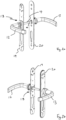
- FIG 1 shows a door handle arrangement 1 according to the present disclosure.
- the door handle arrangement 1 comprises a first handle 2, a second handle 3 and a spindle 4 extending therebetween.
- the handles 2, 3 each comprise handle levers 12, 13 which may take any suitable form known in the art (including door knobs, for example).
- the spindle 4 is attached to each of the first 2 and second 3 handles so as to be rotatable about a spindle axis 5 upon rotation of either or both of the first 12 and second 13 handle levers.
- the handle arrangement 1 is for use with a convention door 100 (see Figure 7 ) which may be received within an opening or frame of a building and used in a conventional manner. Given the conventional nature of the door, it is not shown nor described further.
- the door handle arrangement 1 of the present disclosure is particularly, though not exclusively, useful for external doors.
- the first handle 2 may be considered to be and referred to as an internal handle and the second handle 3 may be considered to be and referred as an external handle, in some embodiments.
- the spindle 4 is operably engaged with a latch mechanism 900 (shown in Figure 9 ) such that rotating the spindle 4 with either of the first 12 or second 13 handle levers operates the latch mechanism such that the door 100 can be opened.
- a latch mechanism 900 shown in Figure 9
- the door handle arrangement 1 may be provided in a "locked” state in which the external handle 3 is disengaged from the spindle 4 such that rotating the handle lever 13 does not cause the rotation of the spindle 4.
- the external handle lever 13 When provided in an “unlocked” state, the external handle lever 13 may be engaged with the spindle 4 such that rotating the external handle 3 rotates the spindle 4 and operates the latch.
- locked state and unlocked state are used here in relation to the respective decoupling and coupling of the handle lever 13 to the spindle 4 to render the handle as being operable to disengage the door latch, rather than engaging or disengaging a lock per se.
- the engagement between the spindle 4 and the handle levers 12, 13 may be achieved via an electronic drive which is operatable via an electronic access key.
- the door handle arrangement 1 may be provided with an electronic reader 9 which is configured to a read an electronic access key presented by a user.
- An example of an electronic drive is provided in Figure 8a and 8b which is described below. It will be appreciated that other means of engaging the handle lever 13 and spindle 4 may exist, and the handles 2,3 may comprise some other form of engagement in which the spindle 4 is held in place to prevent rotation when the door 100 is in a locked condition.
- the handle arrangement 1 of the present disclosure may comprise a spindle lock 18 which is operable upon removal of the handle 3 and/or handle lever 13. Hence, should the handle lever 13 be removed or otherwise damaged so that access to the spindle 4 is achieved, then the spindle lock 18 may automatically engage to prevent direct rotation of the spindle 4 from the exterior side of the door 100, thereby preventing unauthorised opening.
- the spindle lock 18 may be incorporated on an internal side, e.g. a secure side, of the door 100 such that it is not possible to access the spindle lock 18 if the handle 3 on the opposing side is removed.
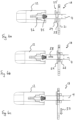
- Figures 2a and 2b show the door handle arrangement 1 of Figures 1a and 1b with the handle housings 10, 11 removed to reveal the back-plates 19, 20 of each handle 2, 3, and a spindle lock 18 according to one embodiment of the present disclosure.
- the handle levers 12, 13 and spindle 4 are as previously presented in Figures 1a and 1b and not described again here.
- Figure 2a shows a view of the spindle lock 18 as being part of the internal door handle 2, with Figure 2b showing the spindle engagement on the external handle 3.
- the spindle lock 18 is shown in more detail in Figures 3, 4 , 5a to 5c and Figure 6a-6c .
- Figure 3 shows the spindle lock 18 in the stowed position
- Figure 4 shows the spindle lock 18 in the engaged position
- Figures 5a-5c show the principal components of the spindle lock 18 with Figure 5a showing an exploded view
- Figure 5b showing the stowed position from the internal handle side
- Figure 5c showing the engaged position from the internal handle side
- Figures 6a-6c show a cross section of the internal handle 2 to better illustrate the operation of the spindle lock 18.
- the spindle lock 18 may comprise a spindle lock-plate 21 which is movable relative to the spindle 4 between a stowed position and an engaged position.
- the spindle lock-plate 21 is configured to move vertically downwards in relation to the spindle 4 when transitioning between the stowed and engaged positions.
- the movement of the lock-plate 21 is enabled by an axial shift in the position of the spindle 4 and is gravity driven.
- the lock-plate 21 may be additionally or alternatively spring actuated such that a spring is used to drive the lock-plate into the engaged position when the spindle and lock-plate are suitably aligned. This may be desirable to provide a more definitive actuation, for example.
- the lock-plate 21 may comprise an aperture 22 into which the spindle 4 can be received in the stowed and engaged positions.
- the aperture 22 may include multiple portions which correspond to the rotatable and engaged configurations of the lock-plate 21.
- the aperture 22 may comprise a rotation portion 23 in which the spindle 4 may be rotatably received in the stowed position, and a lock portion 24 in which the spindle 4 is fixedly received when in the engaged position such that the spindle 4 is prevented from rotation.
- a rotation portion 23 of the lock-plate aperture 22 may comprise a circular peripheral wall such that the spindle 4 might be rotatably received therein.
- first and second curved lateral edges which are located on the outside of and concentrically aligned with the longitudinal axis 33 of the spindle when the lock-plate 21 is in the stowed position.
- the lock portion 24 of the aperture 22 may comprise lateral edges which correspond to but are slightly wider than the spindle cross-section such that the spindle 4 can be readily received therein when the lock-plate 21 falls under gravity and prevented from rotating about axis 33.
- the spindle 4 is square sectioned in the described embodiment, which lends itself to the engaging portion of the aperture having parallel sides but this need not be the case and other configurations of spindle 4 and aperture 22 are possible.
- An optional third portion 34 of the aperture 22 may also be provided to accommodate one or more fixing bolts in both the stowed and engaged positions.
- the third portion may comprise an elongate vertically oriented slot which may extend from the rotation portion 23.
- the lock-plate 21 may be provided in a vertical orientation and generally parallel to the door leaf and/or the back-plate 19 of the door handle 2.
- the lock-plate 21 may comprise a plate of a suitable size and shape for it to fit slidably within the outer handle housing 10 whilst having suitable rigidity to prevent the spindle 4 rotating when in the locked position.
- the plate 21 is generally rectangular with its major axis in the vertical orientation.
- the lock-plate 21 may be located within the handle housing 10 or an internal housing structure which surrounds the lock-plate 21 to prevent rotation relative to the handle 2 when in the engaged position.
- the handle 2 may comprise a handle body 17, which includes a chamber in which the lock-plate 21 is slidably received.
- An example of handle body 17 can be seen in Figure 10 , in which a lock-plate chamber 21' is provided around the base of the handle lever 12.
- the lock-plate 21 may be configured to be movable between the stowed position and the engaged position and this may be achieved using gravity.
- the handle arrangement 1 may comprise one or more guide members.
- the guide members may also include an axial limiter to prevent the axial movement of the lock-plate 21 relative to the back place 19.
- the guide members may be appended from back-plate 19 or an adjacent structure such as the walls of the handle housing 10 or an internal housing structure (not shown).
- the width of the lock-plate 21 may be chosen to correspond to a surrounding enclosure, e.g. the handle housing 10, such that the outer edges of the plate 21 are guided during the downward sliding motion.
- the lock-plate 21 may be guided solely by the engagement with spindle.
- the guide members may comprise lateral tracks which prevent excessive lateral movement and/or one or more linear bearing tracks which reduce the contact area between the lock-plate 21 and surrounding structures such as the back-plate 19.
- the arrangement may comprise linear bearing tracks 39 which are provided between the lock-plate 21 and the back-plate 19.
- the bearing tracks may be narrow vertical strips which provide a small contact area.
- the spindle 4 may be comprise an external profile which corresponds to the aperture portions 23 and 24 when placed at different axial positions.
- the spindle 4 may comprise a first section which is configured to be received by the first portion 23 when the spindle 4 is in a first axial position, and a second section which is configured to engage with the second portion 24 when the spindle 4 is in a second axial position.
- the spindle 4 may further comprise a lock-plate collar 25 which is attached to the spindle 4 to provide a mechanical fixture with which the lock-plate 21 can engage.
- a collar 25 makes the fabrication of the spindle 4, which may otherwise be conventional, more straightforward.
- the collar 25 may comprise a body 26 which comprises portions which are shaped and sized to correspond and engage with the lock-plate 21 in the different operative states, i.e. the stowed and engaged configuration, as discussed above.
- the collar body 24 may comprise a rotation portion 27 for engaging with the rotation portion 23 of the lock-plate 21, and a lock portion 28 for engaging with the lock portion 24 of the lock-plate 21.
- the rotation portion 27 and lock portion 28 of the collar 25 may be provided on axially displaced parts of the body 26. Hence, when the collar 25 and lock-plate 21 are in a first axial location relative to each other, the rotation portions of the collar 25 and lock-plate 21 are engaged and the spindle 4 can rotate, and when the collar 25 is a second axial position relative to the lock-plate 21, the engagement portions are aligned so that rotation of the collar 25 and spindle 4 is prevented.
- the collar 25 shown in Figure 5a comprises a cylindrical body 26 which extends from an end flange 29.
- the cylindrical body 26 comprises a central through-bore 30 which corresponds to the spindle 4 such that the collar 25 can be mounted on the spindle 4 and secured by a grub screw (or other suitable fixing means) which is received within a threaded bore 31.
- the rotating portion 27 of the cylindrical body 26 is distal to the end flange 29 and comprises a round transverse cross-section such that it can be rotatably received within the first portion 23 of aperture 22.
- the axial length of the rotating portion 27 may be greater than thickness of the lock-plate 21.
- the lock portion 28 may be provided by a second width which is narrower than the rotation portion 27.
- the lock portion 28 may comprise parallel sidewalls and be located proximal to the end flange 29, in between the rotation portion 27 and end flange 29.
- the width of the lock portion 28 corresponds to the width of the second portion 24 of the aperture 21 such that when the collar 26 is received within the second portion 24 it can no longer rotate about the spindle axis of rotation.
- the lock portion 28 may be provided by slots which are recessed into the flanks of the otherwise cylindrical body 26 of the collar 25.
- the radial depth of the slots may be sufficient to extend to and expose the central bore 30 and spindle 4 such that the lock-plate 21 may directly engage with the spindle 4 when in the engaged position.
- the end flange 29 may comprise a diameter which is greater than the width of the aperture 22 in the lock-plate 21.
- the flange 29 may act to limit the axial movement of the spindle 4 in relation to the lock-plate 21.
- the spindle 4 may be movable along its axis 33 between an operating/rotatable position and a locked position.
- the spindle 4 may be held and axially contained between the handles 2, 3 in the operating position in a conventional manner. Hence, when the door handle arrangement 1 is operating normally and both door handles 2, 3 are in position and attached to the respective sides of the door 100 the spindle 4 cannot move axially.
- the spindle 4 may be configured to shift axially away from the internal handle 2 such that the lock portion 28 of the spindle collar 25 is axially aligned with the lock-plate 21.
- the lock-plate 21 is able to fall under gravity from the stowed position to surround the spindle 4 and prevent rotation.
- the door handle arrangement 1 may comprise a biasing member which is configured to axially move the spindle 4 upon removal of the external handle 3.
- the biasing member may be any suitable resiliently deformable member which can urge the spindle from the operable, rotating position, to a second axial position in which the lock-plate 21 can engage with the spindle 4 in the engaged position.
- the biasing member may act directly or indirectly on the spindle 4 and may act, for example, on the spindle collar 25.
- relative axial shift between the spindle 4 and the lock-plate 21 may be achieved by moving the lock-plate rather than the spindle 4.
- handle 2 the spindle 4
- lock-plate 21 spindle collar 25
- handle lever 12 the spindle 4
- biasing member 35 which is configured to axially shift the spindle 4 when the external handle, not shown, is removed.
- the biasing member 35 may be located between an axial end face of the spindle 4 and a corresponding opposing surface of the handle 2.
- the opposing surface may be provided directly by the handle lever 12, or by an ancillary structure such as the fixing bolt 36 which attaches the handle lever 12, as shown.
- Other surfaces of the handle may provide a contact surface for the biasing member 35.
- the biasing member 35 may comprise a helical spring or other suitable spring member.
- the spring 35 which is best seen in Figures 6a to 6c , may be a conical spring which is concentrically aligned with the longitudinal and rotational axis of the spindle 33.
- the spring member 35 is compressed by the external handle 3 urging against the distal end of the spindle 4.
- the spindle 4 is no longer restrained and is urged forwards towards the external side of the door 100 by the spring 35, as shown by arrow 38 in Figures 4 and 6b .
- the spindle 4 may comprise a frangible portion such that it might break when an excessive shear or torsional force is applied to it.
- the frangible portion may be configured such that the spindle 4 breaks as the external handle 3 is forcibly removed or following the engagement of the lock-plate 21.
- the frangible portion 40 comprises a notch or groove which introduces a mechanical weakness. The notch or groove may be provided on some or all sides of the spindle 4, as required.
- the location of the frangible portion 40 may be selected so as to reduce the amount of spindle 40 which protrudes from the external surface of the door 100 or back-plate 11 once broken. Hence, the frangible portion 40 may be located substantially flush or axially within with the external handle back-plate 11 or skin of the door once the 100 spindle 4 is in the extended axial position. In some embodiments, the frangible portion 40 may be located proximal to the latch gear inside the door 100.
- the back-plates 19, 20 of the handles 2, 3 may be attached to the door directly using appropriate fixings and/or by connecting the back-plates 19, 20 using interconnecting bolts 41.
- interconnecting bolts 41 there may at least three bolts 41 extending between the two back-plates 19, 20 with one towards each end and one provided within a mid-portion.
- the bolts 41 may be any suitable size to provide the necessary strength but will typically be M5 or M6 bolts. The position and number of bolts 41 may vary between embodiments.
- the lock-plate 21 may be comprise an aperture 34 configured to accommodate one of the fixing bolts 41 in both the stowed and engaged positions thereby allowing the positioning of the bolts as required.
- the internal door handle 2 may comprise additional fixings to attach the internal back-plate 19 to the internal skin of the door 100.
- the additional fixings may be distributed about the back-plate 19 and be local to the spindle 4 such that the internal back-plate 19 is provided with additional security should the connecting bolts 41 be broken or the external back-plate 20 be removed.
- the provision of additional fixings may allow the internal back-plate 19 and lock-plate to be retained in place should the external back-plate be removed.
- removal of the interconnecting bolts 41 would leave the internal back-plate 19 and spindle 4 unattached and removable, thereby allowing the spindle to be turned or removed and an improvised spindle to be used.
- the additional fixings 42 may comprise conventional bolts or screws which are received by the internal skin of the door 100.
- the spindle engagement mechanism 7 is shown in further detail in Figures 8a and 8b .
- the spindle engagement mechanism 7 is operable to couple the external handle 3 to the spindle 4 such that rotating the handle 3, rotates the spindle 4.
- the way in which this is achieved may vary between embodiments, however, in the embodiment shown in Figures 8a and 8b the spindle engagement comprises a bolt 44a which is movable from a stowed position in which the bolt 44a does not engage with the spindle 4, to an engaged position in which the bolt 44a engages with the spindle and the handle 3.
- Figure 8a shows an aperture 44 in a collar 46 of the external handle lever 13. The collar 46 is attached to the handle lever 13 so as to be rotatable therewith.
- the aperture 44 is configured to receive the bolt 44a which is moved radially inwards towards the spindle 4 when actuated.
- the bolt 44a is received within a bolt hole in the spindle 4 so as to rotatably couple the handle collar 46 and spindle 4 together. Hence, once engaged, rotating the handle lever 13 causes the spindle 4 to rotate.
- the actuation mechanism for the bolt 44a is provided by a worm drive 48 which is driven by a small electric motor 49.
- the motor 49 When the motor 49 is energised, the rotor 49a rotates the worm drive 48 which moves an actuator body 50 downwards towards the collar 46 so as to drive the bolt 44a into the collar 46 and spindle 4.
- the actuartor body 50 is shown with the reduced separation in Figure 8b .
- the actuator body 50 comprises a shoe portion 50a which provides a runner against which the bolt 44a can slide during the rotation of the handle lever 13 such that the bolt 44a is continually urged into the collar 46 and handle lever 13. Once the actuator body 50 is retracted, the bolt 44a is urged radially outwards by a spring housed within the collar 14 thereby disengaging the handle lever 13 and spindle 4.
- the operation of the motor 49 may be controlled via an electronic key (not shown) which may be presented to the reader 9 by a user.
- the reader 9 may be configured to communicate with the key via any suitable short range protocol such as Bluetooth Low Energy, BLE, (RTM) or Near Field Communication, NFC, which are well known in the art. It will be appreciated that a reader 9 may also be provided on the internal handle 2 (as shown in Figure 1a ) and that a power source in the form of batteries or the like may also be incorporated in the handle arrangement 1.
- a cable 8 may connect the external and internal handles 3, 2 to transmit signals or power therebetween.
- the electronic access key may be provided in the form of a key fob or mobile phone as well known in the art.
- the door handle arrangement 1 may comprise a conventional latch bolt which is operable via the door handle to open and close the door.
- the door may also comprise a deadbolt which is operable with a mechanical key or thumb-turn.
- the first handle 2 may comprise an aperture 6 for presenting the barrel of a conventional cylinder lock such that the door 100 is lockable with a mechanical key or thumb turn.
- the mechanical lock is operable from the first 2, internal handle only, but this is not a limitation and a mechanical lock may be additionally or alternatively operable via the second handle 3.
- a typical latch mechanism 900 which may be used with the door handle arrangement 1 is shown in Figure 9 and includes a latch bolt 912 and a dead bolt 914 housed within a lock case 916 (which may be referred to as a latch mechanism housing).
- the latch bolt 912 is repeatably retractable via the follower 918 which receives the rotatable spindle 4.
- a lock cylinder 920 is operably connected to the deadbolt 914 and is exposed through the aperture 6 on the internal door handle housing 10 and/or the external door handle housing 11.
- the cylinder lock 920 shown in Figure 9 may be a Euro lock cylinder (which may be referred to as a pin tumbler lock) and may comprise a body portion 920a, which houses spring loaded driver pins, and a barrel 920b which houses key pins. Rotating the barrel with a suitable key turns an internal cam (not shown) thereby actuating the dead bolt 914.
- a pin tumbler lock which may be referred to as a pin tumbler lock
- the cylinder lock 920 shown in Figure 9 may be a Euro lock cylinder (which may be referred to as a pin tumbler lock) and may comprise a body portion 920a, which houses spring loaded driver pins, and a barrel 920b which houses key pins. Rotating the barrel with a suitable key turns an internal cam (not shown) thereby actuating the dead bolt 914.
- the cylinder 920 passes readily but snugly through a suitably sized aperture within the back-plate and is exposed externally through an aperture in the outer casing of the door handle.
- a typical handle housing aperture 6 may be seen in Figure 1a , for example.
- latch mechanisms 920 In order to accommodate different markets and requirements, it is known to provide latch mechanisms 920 of different sizes.
- the size of a latch mechanism 920 may vary in different dimensions such as the casing height, casing depth, backset, which is the distance between the centre of the follower 918 and the front of the case 916, and the so-called PZ spacing, which is the distance between the centre of the follower 918 and the centre of the lock cylinder 920, as shown in Figure 9 with the reference sign 'PZ'.
- PZ spacings comprise a plurality of conventional dimensions included in the group comprising: 92mm, 85mm, 72mm, 70mm and 64mm, but others may be possible.
- door handles and latch mechanisms are conventionally selected to have corresponding dimensions at the point of purchase. However, this results in manufacturers and stockists having to provide multiple different door handles and latch mechanisms.
- Figure 10 shows a door handle arrangement 1 in which a portion of the outer handle housing 10 of the internal handle 2 has been removed to reveal a handle body 17 which is mounted to the back plate 19. It will be appreciated that the rear side of the back-plate 19 which abuts the door 100 corresponds to that shown on the opposing external door handle 3.
- the body 17 and back-plate 19 each comprise a cylinder aperture 1050 which is configured to receive a lock cylinder 920 at various spacings from the spindle centre 1051 (which is shown in Figures 9 and 11 ).
- the door handle 2 may be used with different lock mechanisms 900 having different PZ spacings.
- the cylinder aperture 1050 is generally elongate and may have a lower portion 1050L and an upper portion 1050U.
- the lower portion 1050L may be configured to receive the body 920a of the lock cylinder 920.
- the upper portion 1050U may be configured to receive the barrel 920b.
- the lower portion may have a width which is narrower than the upper portion and may correspond to the width of the lock cylinder body 920a. For a Euro lock, this dimension may be 10mm with enough clearance to allow the lock to be readily received.
- the upper portion 1050U may have a width which corresponds to the width of the barrel portion 920 of the lock cylinder 920, which, for a Euro lock, is approximately 17mm.
- the transition between the lower 1050L and upper 1050U portion is provided by a curved shoulder.
- the curved shoulder may have a radius which matches the radius of the lock barrel 920b, but this is not a limitation.
- the height of a standard Euro lock cylinder is 33mm.
- the aperture 1050 which is configured to accommodate various Euro lock PZ spacings will be greater than 33mm.
- 92mm, 85mm, 72mm, 70mm and 64mm meaning the overall height of the aperture may be anywhere between 35mm and 61mm.
- the aperture 1050 may only be sized to accommodate a select number of the possible PZ spacings. In the most extreme case, this would require the aperture 1050 to be long enough to accommodate two of the adjacent spacings in the group comprising 92mm, 85mm, 72mm, 70mm and 64mm.
- the smallest height for a Euro lock may be 35mm, which would accommodate a PZ spacing of 70mm and 72mm.
- the height of the lower portion 1050L may correspond to the height of the lock cylinder 920a.
- the height of the upper portion 1050U will be determined by the required PZ spacings.
- the shape of the aperture 1050 may vary between embodiments and will depend on the shape of the lock in question.
- the shape of the aperture 1050 broadly corresponds to a Euro lock cylinder profile with an elongated upper portion.
- the lock cylinder may be maintained in place by the latch casing and may not forcibly contact the back plate or handle body.
- minimising the aperture such that it corresponds to the shape of the lock allows the strength of the handle which is beneficial, particularly local to the fixings.
- the outer handle housing 10 is required to have a lock aperture 6 (see Figure 1a ) in the correct position and having the correct size to snugly receive the lock cylinder 920.
- Figure 11 includes various outer handle housings 10a-10e for the door handles 2, 3, each with a cylinder aperture 6a-6e located to suit a particular latch mechanism 900 with a given PZ spacing.
- the outer handle housings 10a-10e are for the conventional PZ spacings provided above.
- the dashed line 1051 shows the position of the spindle centre with the lines PZ1-PZ5 showing the relative PZ spacings for each handle housing 10a-10e. It will be appreciated that the elongate lock aperture 1050 is shown by the dashed line.
- the present disclosure contemplates providing a single door handle to suit multiple different latch mechanisms having different PZ dimensions. It will be appreciated that this aspect of the present disclosure may be applied to any suitable door handle and is not limited to a door handle having the aforementioned spindle lock or electronic lock. Indeed, this aspect of the disclosure may be used with a conventional door handle and latch mechanism where there is a desire to provide a single handle for multiple latch sizes. Further, the handle arrangement 1 may not incorporate the elongate aperture 1050 disclosed herein.
- the handle housings 6a-6e shown in Figure 11 are configured to cover the lower half of the door handle only (from the handle downwards). Hence, the upper edge of the handle housings 6a-6e are shaped to mate with a corresponding edge of the handle lever 12 as provided, for example, by the rose 12a. However, this is not a limitation and the handle housings 6a-6e may be full covers in some embodiments, or further reduced in vertical dimensions so as to only cover a smaller portion of the handle 2 which is local to the lock aperture 6a-6e.
- the handle housings 6a-6e may be attached to the door handle 2 by any suitable means.
- the housings 6a are attached by using a fixing in the form of a grub screw 52 which is received through a hole 53a-53e in the bottom of the housing 6a-6e, and a two part clip fastener which may comprise one or more pips (not shown) on the inside of the housing 6a-6e which is received within a corresponding depression 54 on the handle body 17, or vice versa.
Applications Claiming Priority (1)
| Application Number | Priority Date | Filing Date | Title |
|---|---|---|---|
| GB2202674.4A GB2616059A (en) | 2022-02-25 | 2022-02-25 | A Door Handle Arrangement |
Publications (2)
| Publication Number | Publication Date |
|---|---|
| EP4234850A1 true EP4234850A1 (fr) | 2023-08-30 |
| EP4234850A8 EP4234850A8 (fr) | 2023-10-11 |
Family
ID=81075580
Family Applications (1)
| Application Number | Title | Priority Date | Filing Date |
|---|---|---|---|
| EP23158338.6A Pending EP4234850A1 (fr) | 2022-02-25 | 2023-02-23 | Agencement de poignée de porte |
Country Status (2)
| Country | Link |
|---|---|
| EP (1) | EP4234850A1 (fr) |
| GB (1) | GB2616059A (fr) |
Citations (5)
| Publication number | Priority date | Publication date | Assignee | Title |
|---|---|---|---|---|
| DE373259C (de) * | 1923-04-10 | Rudolf Benda | Schloss, insbesondere fuer Eisenbahnwagen | |
| US4989430A (en) * | 1987-11-05 | 1991-02-05 | Titon Hardware Limited | Latch mechanism |
| GB2474371A (en) * | 2008-06-26 | 2011-04-13 | Avocet Hardware Ltd | Cylinder lock having weakened section |
| EP3385473A1 (fr) * | 2017-04-07 | 2018-10-10 | Patlock Design Limited | Appareil de broche et son procédé d'utilisation |
| US20190119963A1 (en) * | 2014-01-01 | 2019-04-25 | Brisbin Marvin Skiles | Door Locking Device |
Family Cites Families (11)
| Publication number | Priority date | Publication date | Assignee | Title |
|---|---|---|---|---|
| GB191019413A (en) * | 1909-08-18 | 1911-03-09 | Anglo Oesterreichische Bank | Improvements in or relating to Fastenings for Doors or the like. |
| DE3214497A1 (de) * | 1982-04-20 | 1983-10-20 | Alois 8411 Winkerling Schmid | Schloss, insbes. fuer stalltueren |
| DE8914633U1 (fr) * | 1989-12-08 | 1990-02-08 | Ikon Ag Praezisionstechnik, 1000 Berlin, De | |
| DE4014581A1 (de) * | 1990-02-10 | 1991-08-14 | Melchert Beschlaege | Beschlag fuer mit einsteckschloessern und profil-schliesszylindern ausgeruestete tueren |
| DE9102588U1 (fr) * | 1991-03-05 | 1991-05-23 | Hoppe Gmbh & Co Kg, 3570 Stadtallendorf, De | |
| DE29803955U1 (de) * | 1998-03-06 | 1998-04-30 | Hoppe Ag | Türbeschlag |
| GB0613587D0 (en) * | 2006-07-07 | 2006-08-16 | Heeley Peter | Door latch face plate assembly |
| EP2998463B1 (fr) * | 2014-09-22 | 2018-11-07 | dormakaba Deutschland GmbH | Armature pour une porte de bâtiment et procédé |
| GB201502326D0 (en) * | 2015-02-12 | 2015-04-01 | Bowman Alan And Knott Craig | Locking apparatus for handle spindle and method of use thereof |
| CN113396265B (zh) * | 2019-02-11 | 2023-03-10 | 品谱股份有限公司 | 把手组件的支撑结构 |
| FR3109788B1 (fr) * | 2020-04-30 | 2022-05-06 | Christophe Leturgie | Kit d’adaptation d’une porte pour son ouverture par pédale |
-
2022
- 2022-02-25 GB GB2202674.4A patent/GB2616059A/en active Pending
-
2023
- 2023-02-23 EP EP23158338.6A patent/EP4234850A1/fr active Pending
Patent Citations (5)
| Publication number | Priority date | Publication date | Assignee | Title |
|---|---|---|---|---|
| DE373259C (de) * | 1923-04-10 | Rudolf Benda | Schloss, insbesondere fuer Eisenbahnwagen | |
| US4989430A (en) * | 1987-11-05 | 1991-02-05 | Titon Hardware Limited | Latch mechanism |
| GB2474371A (en) * | 2008-06-26 | 2011-04-13 | Avocet Hardware Ltd | Cylinder lock having weakened section |
| US20190119963A1 (en) * | 2014-01-01 | 2019-04-25 | Brisbin Marvin Skiles | Door Locking Device |
| EP3385473A1 (fr) * | 2017-04-07 | 2018-10-10 | Patlock Design Limited | Appareil de broche et son procédé d'utilisation |
Also Published As
| Publication number | Publication date |
|---|---|
| GB202202674D0 (en) | 2022-04-13 |
| GB2616059A (en) | 2023-08-30 |
| EP4234850A8 (fr) | 2023-10-11 |
Similar Documents
| Publication | Publication Date | Title |
|---|---|---|
| US6860129B2 (en) | Security classroom function lock mechanism | |
| US8011702B2 (en) | Outer operational device for panic exit door lock | |
| CA3008424C (fr) | Ensemble de cadenas | |
| US20090038353A1 (en) | Dual lock apparatus | |
| US20090282879A1 (en) | Lock assembly with rotary locking member | |
| KR20080095832A (ko) | 출입문용 보안 장치 | |
| CA2650128A1 (fr) | Verrou electronique a pene dormant | |
| EP1192325B1 (fr) | Dispositif de blocage de porte | |
| US20120060726A1 (en) | Emergently Openable Safe Door | |
| US7343763B2 (en) | Cylinder lock with modified cam | |
| AU2020309101A1 (en) | A lock body for a sliding door | |
| JP2022519427A (ja) | ロックアセンブリ | |
| EP4234850A1 (fr) | Agencement de poignée de porte | |
| US8522584B2 (en) | High-security rotating bolt lock | |
| AU2020310079A1 (en) | Latch assembly | |
| AU785407B2 (en) | Improvements in locks | |
| GB2226359A (en) | Improvements in or relating to lockable handle assemblies | |
| KR102449598B1 (ko) | 수동으로 잠금해제가 가능한 오토래치형 도어 잠금장치 | |
| US20230383572A1 (en) | Lock and locking device | |
| GB2281344A (en) | Garage door lock | |
| AU2003255260B2 (en) | Security classroom function lock mechanism | |
| RU2027834C1 (ru) | Дверная защелка | |
| AU2006201255A1 (en) | Improvements in Locks | |
| CN114909027A (zh) | 门的弹出式锁定把手装置及其使用方法 | |
| AU1529500A (en) | Improvements in locks |
Legal Events
| Date | Code | Title | Description |
|---|---|---|---|
| PUAI | Public reference made under article 153(3) epc to a published international application that has entered the european phase |
Free format text: ORIGINAL CODE: 0009012 |
|
| STAA | Information on the status of an ep patent application or granted ep patent |
Free format text: STATUS: THE APPLICATION HAS BEEN PUBLISHED |
|
| AK | Designated contracting states |
Kind code of ref document: A1 Designated state(s): AL AT BE BG CH CY CZ DE DK EE ES FI FR GB GR HR HU IE IS IT LI LT LU LV MC ME MK MT NL NO PL PT RO RS SE SI SK SM TR |
|
| STAA | Information on the status of an ep patent application or granted ep patent |
Free format text: STATUS: REQUEST FOR EXAMINATION WAS MADE |
|
| 17P | Request for examination filed |
Effective date: 20230904 |
|
| RBV | Designated contracting states (corrected) |
Designated state(s): AL AT BE BG CH CY CZ DE DK EE ES FI FR GB GR HR HU IE IS IT LI LT LU LV MC ME MK MT NL NO PL PT RO RS SE SI SK SM TR |
|
| RIN1 | Information on inventor provided before grant (corrected) |
Inventor name: GOLDER, SIMON Inventor name: ROSSALL, ROBERT |
|
| RIN1 | Information on inventor provided before grant (corrected) |
Inventor name: GOLDER, SIMON Inventor name: ROSSALL, ROBERT |