EP4234766A2 - Wasserstoffherstellungssystem und wasserstoffherstellungsverfahren - Google Patents
Wasserstoffherstellungssystem und wasserstoffherstellungsverfahren Download PDFInfo
- Publication number
- EP4234766A2 EP4234766A2 EP23178603.9A EP23178603A EP4234766A2 EP 4234766 A2 EP4234766 A2 EP 4234766A2 EP 23178603 A EP23178603 A EP 23178603A EP 4234766 A2 EP4234766 A2 EP 4234766A2
- Authority
- EP
- European Patent Office
- Prior art keywords
- stack
- power
- water electrolysis
- stacks
- electrolysis stacks
- Prior art date
- Legal status (The legal status is an assumption and is not a legal conclusion. Google has not performed a legal analysis and makes no representation as to the accuracy of the status listed.)
- Pending
Links
- 229910052739 hydrogen Inorganic materials 0.000 title claims abstract description 86
- 239000001257 hydrogen Substances 0.000 title claims abstract description 86
- UFHFLCQGNIYNRP-UHFFFAOYSA-N Hydrogen Chemical compound [H][H] UFHFLCQGNIYNRP-UHFFFAOYSA-N 0.000 title claims abstract description 85
- 238000004519 manufacturing process Methods 0.000 title claims abstract description 63
- 238000005868 electrolysis reaction Methods 0.000 claims abstract description 222
- XLYOFNOQVPJJNP-UHFFFAOYSA-N water Substances O XLYOFNOQVPJJNP-UHFFFAOYSA-N 0.000 claims abstract description 219
- 230000015556 catabolic process Effects 0.000 claims abstract description 111
- 238000006731 degradation reaction Methods 0.000 claims abstract description 111
- 238000000034 method Methods 0.000 claims abstract description 20
- 238000010248 power generation Methods 0.000 claims description 59
- 238000009826 distribution Methods 0.000 claims description 55
- 238000007726 management method Methods 0.000 claims description 18
- 230000005540 biological transmission Effects 0.000 claims description 16
- 238000009472 formulation Methods 0.000 claims description 12
- 239000000203 mixture Substances 0.000 claims description 12
- 238000004364 calculation method Methods 0.000 claims description 2
- 230000000452 restraining effect Effects 0.000 abstract description 5
- 230000008859 change Effects 0.000 description 18
- 230000001276 controlling effect Effects 0.000 description 18
- 238000010586 diagram Methods 0.000 description 10
- 230000002829 reductive effect Effects 0.000 description 9
- 230000003247 decreasing effect Effects 0.000 description 8
- 238000012360 testing method Methods 0.000 description 6
- 230000007704 transition Effects 0.000 description 6
- 230000000875 corresponding effect Effects 0.000 description 5
- 230000007423 decrease Effects 0.000 description 5
- 238000012544 monitoring process Methods 0.000 description 5
- 238000003860 storage Methods 0.000 description 4
- 230000036541 health Effects 0.000 description 3
- 238000004904 shortening Methods 0.000 description 3
- 239000003011 anion exchange membrane Substances 0.000 description 2
- 238000006243 chemical reaction Methods 0.000 description 2
- 238000013523 data management Methods 0.000 description 2
- 239000000446 fuel Substances 0.000 description 2
- 230000006872 improvement Effects 0.000 description 2
- 238000012423 maintenance Methods 0.000 description 2
- 230000002441 reversible effect Effects 0.000 description 2
- 230000008901 benefit Effects 0.000 description 1
- 230000000694 effects Effects 0.000 description 1
- 150000002431 hydrogen Chemical class 0.000 description 1
- 230000000670 limiting effect Effects 0.000 description 1
- 239000012528 membrane Substances 0.000 description 1
Images




Classifications
-
- C—CHEMISTRY; METALLURGY
- C25—ELECTROLYTIC OR ELECTROPHORETIC PROCESSES; APPARATUS THEREFOR
- C25B—ELECTROLYTIC OR ELECTROPHORETIC PROCESSES FOR THE PRODUCTION OF COMPOUNDS OR NON-METALS; APPARATUS THEREFOR
- C25B1/00—Electrolytic production of inorganic compounds or non-metals
- C25B1/01—Products
- C25B1/02—Hydrogen or oxygen
- C25B1/04—Hydrogen or oxygen by electrolysis of water
-
- C—CHEMISTRY; METALLURGY
- C25—ELECTROLYTIC OR ELECTROPHORETIC PROCESSES; APPARATUS THEREFOR
- C25B—ELECTROLYTIC OR ELECTROPHORETIC PROCESSES FOR THE PRODUCTION OF COMPOUNDS OR NON-METALS; APPARATUS THEREFOR
- C25B1/00—Electrolytic production of inorganic compounds or non-metals
- C25B1/50—Processes
-
- C—CHEMISTRY; METALLURGY
- C25—ELECTROLYTIC OR ELECTROPHORETIC PROCESSES; APPARATUS THEREFOR
- C25B—ELECTROLYTIC OR ELECTROPHORETIC PROCESSES FOR THE PRODUCTION OF COMPOUNDS OR NON-METALS; APPARATUS THEREFOR
- C25B15/00—Operating or servicing cells
-
- C—CHEMISTRY; METALLURGY
- C25—ELECTROLYTIC OR ELECTROPHORETIC PROCESSES; APPARATUS THEREFOR
- C25B—ELECTROLYTIC OR ELECTROPHORETIC PROCESSES FOR THE PRODUCTION OF COMPOUNDS OR NON-METALS; APPARATUS THEREFOR
- C25B15/00—Operating or servicing cells
- C25B15/02—Process control or regulation
-
- C—CHEMISTRY; METALLURGY
- C25—ELECTROLYTIC OR ELECTROPHORETIC PROCESSES; APPARATUS THEREFOR
- C25B—ELECTROLYTIC OR ELECTROPHORETIC PROCESSES FOR THE PRODUCTION OF COMPOUNDS OR NON-METALS; APPARATUS THEREFOR
- C25B15/00—Operating or servicing cells
- C25B15/02—Process control or regulation
- C25B15/023—Measuring, analysing or testing during electrolytic production
-
- C—CHEMISTRY; METALLURGY
- C25—ELECTROLYTIC OR ELECTROPHORETIC PROCESSES; APPARATUS THEREFOR
- C25B—ELECTROLYTIC OR ELECTROPHORETIC PROCESSES FOR THE PRODUCTION OF COMPOUNDS OR NON-METALS; APPARATUS THEREFOR
- C25B9/00—Cells or assemblies of cells; Constructional parts of cells; Assemblies of constructional parts, e.g. electrode-diaphragm assemblies; Process-related cell features
- C25B9/70—Assemblies comprising two or more cells
Definitions
- the present disclosure relates to a control system for a hydrogen production system that produces hydrogen by a plurality of water electrolysis stacks.
- the water electrolysis cells In order to improve the service life of the hydrogen production system, it is necessary to restrain the degradation of its component, that is, the water electrolysis cells.
- the water electrolysis method include alkaline electrolysis, proton exchange membrane (PEM) electrolysis, anion exchange membrane (AEM) electrolysis, and the like. It will be described below how the degradation of the PEM electrolytic cell is restrained.
- Non-PTL 1 Non-patent literature 1 C. Rakousky et al., J. Power Sources 342, 38 (2017 ) (Non-PTL 1), the degradation of the water electrolysis cell has the following characteristics:
- JP-A-2020-084259 (PTL 1) describes a technique for individually controlling ON and OFF of the water electrolysis stacks. For example, according to the power variation of renewable energy, the number of operating stacks is increased when the power is large. Further, PTL 1 discloses a technique for selecting a stack to be operated while monitoring the degradation state of the stack in order to prevent shortening of the life due to overuse of the stack.
- the present disclosure has been made in view of the problems described above, and an object of the present disclosure is to provide, in a hydrogen production system that produces hydrogen using a plurality of water electrolysis stacks, a technique capable of effectively restraining a degradation of the water electrolysis stacks.
- any one of an operation priority stack, a stop priority stack, and an intermediate operation stack is allocated as the operation states of the water electrolysis stacks.
- FIG. 1 is a block diagram of a hydrogen production system 1 according to a first embodiment of the present disclosure.
- the hydrogen production system 1 is a system that produces hydrogen using renewable energy or alternating current (AC) power supplied by a power transmission and distribution system.
- the hydrogen production system 1 produces hydrogen by operating water electrolysis stacks 11 using the supplied power.
- the hydrogen production system 1 includes the water electrolysis stacks 11, DC/DC converters 12, an AC/DC rectifier 13, and a power distribution control system 14.
- the water electrolysis stacks 11 produce hydrogen by electrolyzing water.
- FIG. 1 three pairs of water electrolysis stacks 11 are connected in parallel, in which each pair includes two water electrolysis stacks 11, in which the two water electrolysis stacks 11 are connected in series.
- the hydrogen produced by the water electrolysis stacks 11 is output to transportation equipment and storage equipment.
- the AC/DC rectifier 13 converts the AC power supplied to the hydrogen production system 1 into direct current (DC) power and outputs the converted power to the DC/DC converters 12.
- the DC/DC converters 12 supply power to the water electrolysis stacks 11 to control the operation states of the water electrolysis stacks 11.
- the power distribution control system 14 outputs an operation command to the DC/DC converters 12 to control the operation states of the water electrolysis stacks 11 via the DC/DC converters 12.
- the power distribution control system 14 includes an operation plan formulation unit 141, a stack operation allocation unit 142, a power distribution command unit 143, a degradation characteristic data management unit 144, and a degradation rate estimation unit 145.
- the operation plan formulation unit 141 formulates an operation rotation plan for the water electrolysis stacks 11.
- the operation rotation as used herein is an order of allocating one of an operation priority stack, a stop priority stack, and an intermediate operation stack, which will be described below, as the operation state of each water electrolysis stack 11.
- the stack operation allocation unit 142 determines the operation state of each water electrolysis stack 11 according to the operation rotation plan formulated by the operation plan formulation unit 141.
- the power distribution command unit 143 gives current command values to the DC/DC converters 12 such that the water electrolysis stacks 11 operate according to their operation states.
- the degradation characteristic data management unit 144 holds degradation characteristic data describing the degradation characteristics of the water electrolysis stacks 11.
- the operation plan formulation unit 141 can formulate an operation rotation plan according to these degradation characteristics.
- the degradation rate estimation unit 145 estimates the degradation rate of each water electrolysis stack 11 when assuming that the water electrolysis stack 11 is operated according to the plan.
- FIG. 2 illustrates an example of a change with time of the amount of power generation by renewable energy.
- the amount of power generation by wind power generation is illustrated.
- the upper limit output of the water electrolysis stacks may sometimes be limited as illustrated in FIG. 2 in order to increase the operation rate of the water electrolysis stacks. This improves the operation rate, but on the other hand reduces the number of water electrolysis stacks that can be stopped. For example, when the power such as that illustrated in FIG. 2 is evenly supplied to eight water electrolysis stacks, the operation rate of the water electrolysis stacks is 84.8%.
- FIG. 3 illustrates an example of the operation rotation formulated by the operation plan formulation unit 141 according to the present embodiment.
- the operation plan formulation unit 141 allocates one of (a) operation priority stack, (b) stop priority stack, and (c) intermediate operation stack as the operation state of the water electrolysis stack 11.
- the operation priority stack is a stack to which power is preferentially distributed as compared with other water electrolysis stacks 11.
- the stop priority stack is a stack for which the power supply is preferentially stopped as compared with the other water electrolysis stacks 11.
- the intermediate operation stack is a stack that receives the power supply intermediately between those described above. For example, all the power received by the hydrogen production system 1 is first allocated to the operation priority stack and the stop priority stack, and then when there is remaining power, it is allocated to the intermediate operation stack.
- FIGS. 4A to 4C illustrate a change with time of the power supplied to each water electrolysis stack 11 when each water electrolysis stack 11 is operated according to the operation rotation plan of FIG. 3 .
- the operation priority stack has the highest priority to be distributed with the power, and the stop priority stack has the highest priority to not be distributed with the power.
- the intermediate operation stack receives the power supply intermediately between them.
- FIG. 5 illustrates a table illustrating the results of testing the degradation rates of the water electrolysis stacks. These are described in Non-PTL 1, and illustrate the results of testing the degradation rate (voltage rise rate) in each of five modes.
- the characteristics of the water electrolysis stack that can be seen from these test results will be described, and then the estimation results of when the same test is performed according to the present embodiment will be illustrated.
- the present embodiment uses the water electrolysis stacks and Non-PTL 1 uses a single water electrolysis cell, note that the absolute values of the numbers are different from each other.
- the degradation rate is 194 ⁇ V/h, which is the highest. Therefore, it can be seen that when the operation at high power is continued for a long time (about 1000 hours), the degradation rate is very high (that is, the intermittent operation in which the output is lowered in the middle is desirable).
- the degradation rate is 65 ⁇ V/h
- the degradation rate is 16 ⁇ V/h. Therefore, it can be seen that, during the intermittent operation, degradation can be restrained by transitioning between high power and zero power rather than transitioning between high power and intermediate power.
- mode E the output of 2 A/cm 2 is continued for 10 minutes, and then the output of 0 A/cm 2 is continued for 10 minutes. Therefore, the output cycle is extremely short compared to the other modes (for example, modes C and D have a cycle of 6 hours + 6 hours).
- the degradation rate of mode E is 50 ⁇ V/h
- the degradation rate of mode D is 16 ⁇ V/h. Therefore, it can be seen that the shorter the output cycle, the faster the degradation.
- the operation priority stack according to the present embodiment corresponds to mode D in that the stop priority stack is allocated after the operation at high power, the resulting degradation is 16 ⁇ V/h continuously for 6 hours. Since the stop priority stack according to the present embodiment frequently transitions between the high power and the zero power, this corresponds to the mode E, and the resulting degradation is 50 ⁇ V/h continuously for 6 hours. Since the intermediate operation stack according to the present embodiment frequently switches ON and OFF in addition to transitioning between the high power and the intermediate power, the degradation rate is 99 ⁇ V/h as described above, which continues for 6 h ⁇ 2. Therefore, the degradation rate in this embodiment is 66 ⁇ V/h on average for each operation mode, and the degradation rate can be reduced by 33% as compared with the related example.
- FIG. 6 illustrates an example of an operation rotation plan when six water electrolysis stacks 11 are operated.
- FIGS. 7A to 7C illustrate a change with time of the power supplied to each water electrolysis stack 11 when each water electrolysis stack 11 is operated according to the operation rotation plan of FIG. 6 .
- the degradation rate is estimated in the same manner as in the example of FIGS. 3 to 4C (first example), the degradation rate is 55 ⁇ V/h, and the degradation rate can be reduced by 44% as compared with the related example. It is considered that the degradation restraining effect is greater in this example (second example) than in the first example because the ratio of the number of operation priority stacks and stop priority stacks having a relatively low degradation rate is increased.
- the operation rate of the operation priority stack is decreased (comparison between FIGS. 4A and 7A ), and the operation rate of the stop priority stack is increased (comparison of FIGS. 4B and 7B ).
- the accuracy of approximation that regards the degradation rate of the operation priority stack as corresponding to mode D is decreased. That is, even for the same operation priority stack, there is a possibility that the degradation rate of the second example is higher than that of the first example. Therefore, it is effective to formulate the operation rotation while pre-evaluating the degradation rate for each input power data or acquiring the same during operation.
- the degradation rate estimation unit 145 may estimate the degradation rate of each water electrolysis stack 11 under the current operation rotation plan, and the operation plan formulation unit 141 may formulate a rotation plan such that the difference in the degradation rate between the water electrolysis stacks 11 is as small as possible. It is not always necessary to make the degradation rates of the water electrolysis stacks 11 exactly equal, and as long as at least the difference in the degradation rates between the stacks is reduced, the corresponding effect can be exhibited.
- FIG. 8 illustrates an example of a change with time of the amount of power generation by photovoltaic power generation. It can be seen that the amount of power generation varies according to the time of day, and that the amount of power generation decreases due to the influence of clouds. An example in which this power is supplied to the hydrogen production system 1 will be considered below.
- FIG. 9 illustrates a change with time of the power distributed to the operation stacks when the supplied power in FIG. 8 is distributed to the water electrolysis stacks according to the related procedure.
- the amount of power generation changes greatly according to the time of day as in photovoltaic power generation, since the output is filtered with reference to the upper limit as illustrated in FIG. 2 , it is difficult to increase the operation rate of the water electrolysis system. Therefore, first, as an example of the related controlling, as disclosed in PTL 1, the result of power distribution when the water electrolysis stacks are switched ON and OFF according to the time zone (amount of power generation) is estimated. In this example, the power is evenly distributed to the eight water electrolysis stacks. FIG. 9 shows the result.
- the average operation rate of the operation stacks illustrated in FIG. 9 is as low as 58.1%, and since frequent transitions between high power and intermediate power are observed, there can be early degradation. Therefore, it can be seen that it is difficult to restrain the degradation of the water electrolysis stacks by the related method of controlling the number of stacks to be switched ON and OFF.
- FIG. 10 illustrates an example of an operation rotation plan when the power supply varies as illustrated in FIG. 8 .
- the operation plan formulation unit 141 allocates the water electrolysis stack 11 that is completely switched OFF (cut off from power supply). This is called the stop stack.
- the stop stack For example, in FIG. 10 , in the period of 0 to 2 h during which the supplied power is small, only four water electrolysis stacks 11 are operated, and in the period of 8 to 10 h during which the supplied power is further decreased, only two stacks are operated.
- water electrolysis stack 11 is to be switched OFF, it may be done in a manner in which the operation rate of each water electrolysis stack 11 is kept as uniform as possible, for example. It is preferable that the average operation rate is kept as uniform as possible over a certain period of time, but it is not always necessary to make the operation rate strictly uniform at all times. Further, it is not always necessary to allocate the stop stack over the entire period when the supplied power is low, and if the stop stack is allocated for at least a portion of the low power period, the degradation restraining effect to that extent can be exhibited.
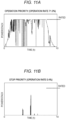
- FIGS. 11A to 11C illustrate a change with time of the power supplied to each water electrolysis stack 11 when each water electrolysis stack 11 is operated according to the operation rotation plan of FIG. 10 . Since the operation priority stack has an improved operation rate and a reduced frequency of transitions between high power and intermediate power as compared with FIG. 9 , it is expected that the degradation rate will be lower than that of the related controlling.
- the number of water electrolysis stacks to be switched ON and OFF is changed in real time (in seconds) according to the variation of the input power.
- the operation rotation of FIG. 10 since the operation states of the water electrolysis stacks 11 can be controlled by the 'current distribution control by the DC/DC converter 12' in addition to 'ON and OFF controlling every 2 hours', there is also an advantage in terms of following capability with respect to variations.
- degradation of the water electrolysis stacks 11 can be restrained as compared with the related operation controlling that equalizes the operation rate of the water electrolysis stack 11 and operation controlling that frequently repeats ON and OFF.
- the hydrogen production system 1 During a period when the supplied power is small, the hydrogen production system 1 according to the first embodiment additionally allocates the stop stack as the operation state of the water electrolysis stacks 11, in addition to that described above. As a result, even when a power supply that greatly varies with time is received as in the case of photovoltaic power generation, degradation of the water electrolysis stacks 11 can be effectively restrained.
- FIG. 12 is a block diagram of a hydrogen production system 1 according to a second embodiment of the present disclosure.
- a power generation amount prediction unit 21 is provided.
- the power generation amount prediction unit 21 may be configured as a part of the hydrogen production system 1 or may be configured as a functional unit separate from the hydrogen production system 1.
- the power generation amount prediction unit 21 predicts the amount of power generation of renewable energy according to a known method. For example, the following may be considered: (a) prediction using meteorological data 22 (data describing meteorological conditions such as weather, wind conditions, and the like); (b) data acquisition on amount of power generation from renewable energy power generation facilities in real time; and (c) a combination of these, and the like.
- meteorological data 22 data describing meteorological conditions such as weather, wind conditions, and the like
- data acquisition on amount of power generation from renewable energy power generation facilities in real time and (c) a combination of these, and the like.
- the power distribution control system 14 receives the predicted amount of power generation from the power generation amount prediction unit 21, and accordingly allocates the operation state of each water electrolysis stack 11. For example, when the amount of power generation is large, the number of operation priority stacks is increased. This is because there is a concern that, when the amount of power generation is increased while maintaining the number of stacks as is, the power distributed to the stop priority stack is increased and the transition between the high power and the intermediate power is increased, which will result in accelerated degradation. Further, as in the case of the photovoltaic power generation of the first embodiment, when the amount of power generation is expected to decrease according to the time zone, ON and OFF of the water electrolysis stacks 11 may be controlled as illustrated in FIG. 10 . With these controlling, degradation of the water electrolysis stacks 11 can be restrained while following variations in the amount of renewable energy power generation.
- FIG. 13 is a block diagram of a hydrogen production system 1 according to a third embodiment of the present disclosure.
- a degradation monitoring unit 3 is provided in addition to the configuration described in the first embodiment.
- the degradation monitoring unit 3 may be configured as a part of the hydrogen production system 1 or may be configured as a functional unit separate from the hydrogen production system 1.
- the degradation monitoring unit 3 receives an output current and an output voltage of the water electrolysis stacks 11 from the power distribution control system 14, and uses the same to calculate the state of health (SOH) of the water electrolysis stacks 11.
- the power distribution control system 14 allocates the operation state of each water electrolysis stack 11 according to the state of health thereof.
- the power distribution control system 14 allocates the operation state such that, for the water electrolysis stack 11 having a reduced SOH, the number of times to perform an operation with a larger degradation rate as compared with the other water electrolysis stacks 11 (for example, the number of times to allocate the intermediate operation stack) is reduced.
- the number of times to perform an operation with a larger degradation rate as compared with the other water electrolysis stacks 11 is reduced.
- FIG. 14 is a block diagram of a hydrogen production system 1 according to a fourth embodiment of the present disclosure.
- a management system 41 and a distributor 42 are provided.
- the management system 41 and the distributor 42 may be configured as parts of the hydrogen production system 1 or may be configured as functional units separate from the hydrogen production system 1.
- the distributor 42 switches between supplying the power generated by a renewable energy power generation facility 43 to the water electrolysis stacks 11 and selling the power to a consumer 44 (that is, outputting the received power to the power transmission and distribution system), according to instruction from the management system 41.
- the management system 41 instructs the distributor 42 on a distribution ratio between the two options.
- the management system 41 further collects demand data for various energies (for example, power, heat, hydrogen, and the like) from the consumer 44, and controls the energy distribution according to the data. For example, it is possible to carry out controlling, such as predicting the power demand and a spot price of energy that reflects the same, increasing a power selling ratio when the power demand is large, producing hydrogen when the power demand is low, and the like. Data for the supply amount of these energies may also be collected, and the controlling described above may be performed according to the balance between supply and demand.
- energies for example, power, heat, hydrogen, and the like
- the distributor 42 may increase the ratio of selling power to the consumer 44 (in other words, when the amount of power generation is decreased, the ratio of selling power is decreased accordingly).
- the power supplied to the water electrolysis stack 11 is reduced, the number of stacks that can be allocated as the stop priority stack is increased. As a result, degradation of the water electrolysis stacks 11 can be restrained.
- FIG. 15 is a block diagram of a hydrogen production system 1 according to a fifth embodiment of the present disclosure.
- the hydrogen production system 1 receives power from a power transmission and distribution system 5. Therefore, unlike the case of receiving renewable energy power, a constant current load is applied to the water electrolysis stacks 11, and accordingly, it is necessary to consider the degradation for this.
- Other configurations are the same as those of the first to fourth embodiments.
- FIG. 16A illustrates the operation rotation when the operation state of each water electrolysis stack is allocated according to the related procedure.
- the numerical values are the current densities (A/cm 2 ) supplied to the water electrolysis stacks.
- the power is evenly distributed to each stack.
- FIG. 16B illustrates the operation rotation of the hydrogen production system 1 according to the present embodiment.
- the stack with the current value of 1.8 A/cm 2 roughly corresponds to the operation priority stack
- the stack with the current value of 1.0 A/cm 2 roughly corresponds to the stop priority stack. Therefore, by allocating these as the operation states of the stacks of FIG. 16B , the same effect as that of the first embodiment can be exhibited.
- the current values illustrated in FIG. 16B may be fixed and supplied to the water electrolysis stack 11 as they are. Regarding which one is to be used, it may be switched according to the type of power supplied.
- the degradation rate in the related controlling of FIG. 16A is estimated to be 78 ⁇ V/h by linearly interpolating the degradation rate in mode B of FIG. 5 .
- the degradation rate in FIG. 16B is estimated to be 52 ⁇ V/h by linearly interpolating the degradation rate in mode C. Therefore, the degradation rate can be reduced by 33% as compared with the related controlling. Therefore, even when receiving a power that varies little with time, such as a system power, degradation of the water electrolysis stacks 11 can be restrained.
- the present disclosure is not limited to the embodiments described above, and includes various modified examples.
- the embodiments described above are described in detail in order to explain the present disclosure in an easy-to-understand manner, and are not necessarily limited to those having all the configurations described above.
- a part of the configuration of an embodiment can be replaced with the configuration of another embodiment, and the configuration of another embodiment can be added to the configuration of an embodiment.
- Non-PTL 1 In the degradation test of Non-PTL 1, it is described that a voltage of 1.4 V or more is applied to the water electrolysis cell even when the current density is zero. This is slightly higher than the theoretical voltage (1.23 V) for electrolysis of water, and is a voltage value near the start of the electrolytic reaction. If the voltage is lowered to 0 V during operation, a reverse current will flow, which may degrade the water electrolysis cell. Therefore, according to the present disclosure, even when the current flowing through the water electrolysis stacks 11 is zero, the DC/DC converters 12 are arranged at the inlets of the paths where power is supplied to the water electrolysis stacks 11 such that a voltage near the start of the electrolysis reaction can be applied to the water electrolysis stacks 11. A role similar to that described above can be replaced by a power converter capable of at least two or more voltage outputs. Therefore, such a power converter may be arranged instead of the DC/DC converter 12.
- the present disclosure can also be applied to a fuel cell operating with the reverse reaction of water electrolysis.
- the water electrolysis stacks 11 are replaced with the fuel cell stacks
- the power distribution control system 14 is replaced with a power generation sharing control system, and the flow of power and hydrogen is reversed.
- the power distribution control system 14 and each functional unit thereof can be configured by hardware such as a circuit device that implements these functions and the like, or can be configured by executing software that implements these functions by a computing unit such as a processor or the like.
- a computing unit such as a processor or the like.
Landscapes
- Chemical & Material Sciences (AREA)
- Engineering & Computer Science (AREA)
- Chemical Kinetics & Catalysis (AREA)
- Electrochemistry (AREA)
- Materials Engineering (AREA)
- Metallurgy (AREA)
- Organic Chemistry (AREA)
- Automation & Control Theory (AREA)
- Inorganic Chemistry (AREA)
- Analytical Chemistry (AREA)
- Electrolytic Production Of Non-Metals, Compounds, Apparatuses Therefor (AREA)
- Supply And Distribution Of Alternating Current (AREA)
Applications Claiming Priority (2)
| Application Number | Priority Date | Filing Date | Title |
|---|---|---|---|
| JP2021023663A JP7518014B2 (ja) | 2021-02-17 | 2021-02-17 | 制御システム、制御方法、水素製造システム |
| EP22154792.0A EP4047112A3 (de) | 2021-02-17 | 2022-02-02 | Wasserstoffherstellungssystem und wasserstoffherstellungsverfahren |
Related Parent Applications (1)
| Application Number | Title | Priority Date | Filing Date |
|---|---|---|---|
| EP22154792.0A Division EP4047112A3 (de) | 2021-02-17 | 2022-02-02 | Wasserstoffherstellungssystem und wasserstoffherstellungsverfahren |
Publications (2)
| Publication Number | Publication Date |
|---|---|
| EP4234766A2 true EP4234766A2 (de) | 2023-08-30 |
| EP4234766A3 EP4234766A3 (de) | 2023-09-27 |
Family
ID=80225651
Family Applications (2)
| Application Number | Title | Priority Date | Filing Date |
|---|---|---|---|
| EP22154792.0A Pending EP4047112A3 (de) | 2021-02-17 | 2022-02-02 | Wasserstoffherstellungssystem und wasserstoffherstellungsverfahren |
| EP23178603.9A Pending EP4234766A3 (de) | 2021-02-17 | 2022-02-02 | Wasserstoffherstellungssystem und wasserstoffherstellungsverfahren |
Family Applications Before (1)
| Application Number | Title | Priority Date | Filing Date |
|---|---|---|---|
| EP22154792.0A Pending EP4047112A3 (de) | 2021-02-17 | 2022-02-02 | Wasserstoffherstellungssystem und wasserstoffherstellungsverfahren |
Country Status (2)
| Country | Link |
|---|---|
| EP (2) | EP4047112A3 (de) |
| JP (1) | JP7518014B2 (de) |
Cited By (1)
| Publication number | Priority date | Publication date | Assignee | Title |
|---|---|---|---|---|
| WO2025168185A1 (en) * | 2024-02-08 | 2025-08-14 | Vestas Wind Systems A/S | Power plant arrangement |
Families Citing this family (6)
| Publication number | Priority date | Publication date | Assignee | Title |
|---|---|---|---|---|
| JP2023141293A (ja) * | 2022-03-23 | 2023-10-05 | 株式会社デンソー | 水素製造システム |
| JP2024033545A (ja) * | 2022-08-30 | 2024-03-13 | 株式会社日立製作所 | 電力変換システムおよびその制御方法 |
| EP4414906A1 (de) * | 2023-02-13 | 2024-08-14 | Abb Schweiz Ag | Verfahren zur steuerung des betriebs einer elektrolyseuranlage |
| DK181808B1 (en) * | 2023-02-17 | 2025-01-21 | Green Hydrogen Systems As | Electrolyser unit comprising a plurality of individual electrolyser stacks and method for connecting electrolyser units |
| EP4576478A1 (de) * | 2023-12-19 | 2025-06-25 | McPhy Energy | Verfahren zur modulierung der von einer wasserelektrolyseanlage aufgenommenen leistung und elektrolyseanlage mit einem solchen verfahren |
| KR20260005440A (ko) * | 2024-07-02 | 2026-01-12 | (주)지필로스 | 모듈화된 복수의 수전해 스택을 포함하는 수전해 시스템 및 이의 운전 방법 |
Citations (1)
| Publication number | Priority date | Publication date | Assignee | Title |
|---|---|---|---|---|
| JP2020084259A (ja) | 2018-11-23 | 2020-06-04 | 株式会社豊田中央研究所 | 水電解システム |
Family Cites Families (9)
| Publication number | Priority date | Publication date | Assignee | Title |
|---|---|---|---|---|
| JP4406866B2 (ja) * | 2003-10-27 | 2010-02-03 | 株式会社Ihi | 水素製造設備 |
| PT2006418E (pt) * | 2007-06-11 | 2012-04-23 | Rech 2000 Inc | Optimização da eficiência e deteção de danos nas células de eletrólise |
| US20110155583A1 (en) * | 2010-03-13 | 2011-06-30 | Haiming Li | High efficient hydrogen generation with green engergy powers |
| EP2781624A1 (de) * | 2013-03-19 | 2014-09-24 | Siemens Aktiengesellschaft | Elektrolysestack und Elektrolyseur |
| JP6731070B2 (ja) * | 2016-12-14 | 2020-07-29 | 株式会社東芝 | 水素エネルギーシステム、水素エネルギーシステムの制御方法、及びプログラム |
| JP6897250B2 (ja) * | 2017-04-07 | 2021-06-30 | 富士通株式会社 | 電解システム、電解制御装置及び電解システムの制御方法 |
| JP6936179B2 (ja) * | 2018-03-28 | 2021-09-15 | 東邦瓦斯株式会社 | 水素製造システム |
| CN112103994B (zh) * | 2020-08-25 | 2022-04-01 | 同济大学 | 一种基于mpc的风氢耦合系统分层协调控制方法及装置 |
| US11519089B1 (en) * | 2021-08-16 | 2022-12-06 | Dioxycle | Methods and systems for automated optimization of COx electrolysis reactor |
-
2021
- 2021-02-17 JP JP2021023663A patent/JP7518014B2/ja active Active
-
2022
- 2022-02-02 EP EP22154792.0A patent/EP4047112A3/de active Pending
- 2022-02-02 EP EP23178603.9A patent/EP4234766A3/de active Pending
Patent Citations (1)
| Publication number | Priority date | Publication date | Assignee | Title |
|---|---|---|---|---|
| JP2020084259A (ja) | 2018-11-23 | 2020-06-04 | 株式会社豊田中央研究所 | 水電解システム |
Non-Patent Citations (1)
| Title |
|---|
| C. RAKOUSKY ET AL., J. POWER SOURCES, vol. 342, 2017, pages 38 |
Cited By (1)
| Publication number | Priority date | Publication date | Assignee | Title |
|---|---|---|---|---|
| WO2025168185A1 (en) * | 2024-02-08 | 2025-08-14 | Vestas Wind Systems A/S | Power plant arrangement |
Also Published As
| Publication number | Publication date |
|---|---|
| JP7518014B2 (ja) | 2024-07-17 |
| EP4234766A3 (de) | 2023-09-27 |
| JP2022125850A (ja) | 2022-08-29 |
| EP4047112A2 (de) | 2022-08-24 |
| EP4047112A3 (de) | 2023-03-01 |
Similar Documents
| Publication | Publication Date | Title |
|---|---|---|
| EP4234766A2 (de) | Wasserstoffherstellungssystem und wasserstoffherstellungsverfahren | |
| US20220285950A1 (en) | Energy storage system and battery management method | |
| JP6482541B2 (ja) | 電気エネルギを電気化学エネルギ蓄積装置に貯蔵する方法及び装置 | |
| US9303325B2 (en) | Power dispatch system for electrolytic production of hydrogen from wind power | |
| US9496725B2 (en) | Power control apparatus, method, program, and integrated circuit, and storage battery unit | |
| EP4239825B1 (de) | Leistungssteuerungssystem für elektrolyseur | |
| EP4137609A2 (de) | Wasserstofferzeugungssystem, verfahren zur produktion von wasserstoff | |
| EP4261325A2 (de) | Wasserstoffherstellungssystem, wasserstoffherstellungsverfahren | |
| EP4195440A1 (de) | Energieverteilungssystem und verfahren zur steuerung der energieverteilung | |
| CN114899857A (zh) | 台区电池单元共享型储能系统 | |
| CN106329524A (zh) | 一种微电网系统及微电网系统的控制方法 | |
| GB2627434A (en) | Electrolyzer with variable number of active electrolysis cells | |
| KR101729273B1 (ko) | 복수의 무정전 전원 공급 장치를 포함하는 에너지 저장 시스템의 최대 수요 전력을 제어하는 에너지 관리 시스템 및 이의 동작 방법 | |
| JP2008099527A (ja) | 電力系統に接続された自家発電設備における蓄電池設備および蓄電池設備の運転方法 | |
| EP3567691B1 (de) | Zusammengesetztes energiespeichersystem und energiespeicherverfahren | |
| EP4283813A1 (de) | Wasserelektrolysesystem mit verwaltung der stromversorgung von erneuerbarer energie | |
| US10879548B2 (en) | Power generation system, method for controlling power generation system, and power generation apparatus | |
| Babaiahgari et al. | Coordinated control and optimization of DC power systems | |
| EP4576478A1 (de) | Verfahren zur modulierung der von einer wasserelektrolyseanlage aufgenommenen leistung und elektrolyseanlage mit einem solchen verfahren | |
| JP2024138850A (ja) | 電力供給システム | |
| CN121012008A (zh) | 电能调度系统和电能调度方法 | |
| RU2467450C2 (ru) | Способ снабжения индивидуальных потребителей и способ снабжения электропривода электроэнергией с использованием электрической сети переменного тока | |
| Ahlgren et al. | System performance analysis of an isolated microgrid with renewable energy sources and a battery and hydrogen storage system-An evaluation of different storage system configurations |
Legal Events
| Date | Code | Title | Description |
|---|---|---|---|
| PUAI | Public reference made under article 153(3) epc to a published international application that has entered the european phase |
Free format text: ORIGINAL CODE: 0009012 |
|
| STAA | Information on the status of an ep patent application or granted ep patent |
Free format text: STATUS: REQUEST FOR EXAMINATION WAS MADE |
|
| REG | Reference to a national code |
Ref country code: DE Ref legal event code: R079 Free format text: PREVIOUS MAIN CLASS: C25B0015020000 Ipc: C25B0001040000 |
|
| PUAL | Search report despatched |
Free format text: ORIGINAL CODE: 0009013 |
|
| 17P | Request for examination filed |
Effective date: 20230612 |
|
| AC | Divisional application: reference to earlier application |
Ref document number: 4047112 Country of ref document: EP Kind code of ref document: P |
|
| AK | Designated contracting states |
Kind code of ref document: A2 Designated state(s): AL AT BE BG CH CY CZ DE DK EE ES FI FR GB GR HR HU IE IS IT LI LT LU LV MC MK MT NL NO PL PT RO RS SE SI SK SM TR |
|
| AK | Designated contracting states |
Kind code of ref document: A3 Designated state(s): AL AT BE BG CH CY CZ DE DK EE ES FI FR GB GR HR HU IE IS IT LI LT LU LV MC MK MT NL NO PL PT RO RS SE SI SK SM TR |
|
| RIC1 | Information provided on ipc code assigned before grant |
Ipc: C25B 15/02 20210101ALI20230822BHEP Ipc: C25B 15/00 20060101ALI20230822BHEP Ipc: C25B 1/50 20210101ALI20230822BHEP Ipc: C25B 15/023 20210101ALI20230822BHEP Ipc: C25B 9/70 20210101ALI20230822BHEP Ipc: C25B 1/04 20210101AFI20230822BHEP |
|
| STAA | Information on the status of an ep patent application or granted ep patent |
Free format text: STATUS: EXAMINATION IS IN PROGRESS |
|
| 17Q | First examination report despatched |
Effective date: 20240923 |