EP4137609A2 - Wasserstofferzeugungssystem, verfahren zur produktion von wasserstoff - Google Patents
Wasserstofferzeugungssystem, verfahren zur produktion von wasserstoff Download PDFInfo
- Publication number
- EP4137609A2 EP4137609A2 EP22158339.6A EP22158339A EP4137609A2 EP 4137609 A2 EP4137609 A2 EP 4137609A2 EP 22158339 A EP22158339 A EP 22158339A EP 4137609 A2 EP4137609 A2 EP 4137609A2
- Authority
- EP
- European Patent Office
- Prior art keywords
- stack
- defective
- serial unit
- power
- water electrolysis
- Prior art date
- Legal status (The legal status is an assumption and is not a legal conclusion. Google has not performed a legal analysis and makes no representation as to the accuracy of the status listed.)
- Granted
Links
Images


Classifications
-
- C—CHEMISTRY; METALLURGY
- C25—ELECTROLYTIC OR ELECTROPHORETIC PROCESSES; APPARATUS THEREFOR
- C25B—ELECTROLYTIC OR ELECTROPHORETIC PROCESSES FOR THE PRODUCTION OF COMPOUNDS OR NON-METALS; APPARATUS THEREFOR
- C25B1/00—Electrolytic production of inorganic compounds or non-metals
- C25B1/01—Products
- C25B1/02—Hydrogen or oxygen
- C25B1/04—Hydrogen or oxygen by electrolysis of water
-
- C—CHEMISTRY; METALLURGY
- C25—ELECTROLYTIC OR ELECTROPHORETIC PROCESSES; APPARATUS THEREFOR
- C25B—ELECTROLYTIC OR ELECTROPHORETIC PROCESSES FOR THE PRODUCTION OF COMPOUNDS OR NON-METALS; APPARATUS THEREFOR
- C25B15/00—Operating or servicing cells
- C25B15/02—Process control or regulation
-
- C—CHEMISTRY; METALLURGY
- C25—ELECTROLYTIC OR ELECTROPHORETIC PROCESSES; APPARATUS THEREFOR
- C25B—ELECTROLYTIC OR ELECTROPHORETIC PROCESSES FOR THE PRODUCTION OF COMPOUNDS OR NON-METALS; APPARATUS THEREFOR
- C25B15/00—Operating or servicing cells
- C25B15/02—Process control or regulation
- C25B15/023—Measuring, analysing or testing during electrolytic production
-
- C—CHEMISTRY; METALLURGY
- C25—ELECTROLYTIC OR ELECTROPHORETIC PROCESSES; APPARATUS THEREFOR
- C25B—ELECTROLYTIC OR ELECTROPHORETIC PROCESSES FOR THE PRODUCTION OF COMPOUNDS OR NON-METALS; APPARATUS THEREFOR
- C25B9/00—Cells or assemblies of cells; Constructional parts of cells; Assemblies of constructional parts, e.g. electrode-diaphragm assemblies; Process-related cell features
- C25B9/70—Assemblies comprising two or more cells
-
- Y—GENERAL TAGGING OF NEW TECHNOLOGICAL DEVELOPMENTS; GENERAL TAGGING OF CROSS-SECTIONAL TECHNOLOGIES SPANNING OVER SEVERAL SECTIONS OF THE IPC; TECHNICAL SUBJECTS COVERED BY FORMER USPC CROSS-REFERENCE ART COLLECTIONS [XRACs] AND DIGESTS
- Y02—TECHNOLOGIES OR APPLICATIONS FOR MITIGATION OR ADAPTATION AGAINST CLIMATE CHANGE
- Y02E—REDUCTION OF GREENHOUSE GAS [GHG] EMISSIONS, RELATED TO ENERGY GENERATION, TRANSMISSION OR DISTRIBUTION
- Y02E60/00—Enabling technologies; Technologies with a potential or indirect contribution to GHG emissions mitigation
- Y02E60/30—Hydrogen technology
- Y02E60/36—Hydrogen production from non-carbon containing sources, e.g. by water electrolysis
-
- Y—GENERAL TAGGING OF NEW TECHNOLOGICAL DEVELOPMENTS; GENERAL TAGGING OF CROSS-SECTIONAL TECHNOLOGIES SPANNING OVER SEVERAL SECTIONS OF THE IPC; TECHNICAL SUBJECTS COVERED BY FORMER USPC CROSS-REFERENCE ART COLLECTIONS [XRACs] AND DIGESTS
- Y02—TECHNOLOGIES OR APPLICATIONS FOR MITIGATION OR ADAPTATION AGAINST CLIMATE CHANGE
- Y02P—CLIMATE CHANGE MITIGATION TECHNOLOGIES IN THE PRODUCTION OR PROCESSING OF GOODS
- Y02P20/00—Technologies relating to chemical industry
- Y02P20/10—Process efficiency
- Y02P20/133—Renewable energy sources, e.g. sunlight
Definitions
- This disclosure relates to a hydrogen producing system that produces hydrogen by a plurality of water electrolysis stacks.
- Hydrogen is produced by methods such as water electrolysis. Costs for producing hydrogen are roughly categorized into capital expense (CAPEX) and operating expense (OPEX). OPEX consists of such as procurement cost for electric power used for water electrolysis, system maintenance cost, and the like. In order to reduce CAPEX, approaches such as below are necessary.
- Water electrolysis methods include : alkaline electrolysis, PEM (Proton Exchange Membrane) electrolysis, AEM (Anion Exchange Membrane) electrolysis, etc.
- PEM Proton Exchange Membrane
- AEM Anion Exchange Membrane
- Patent Document 1 discloses, in order to detect the micro short, a technique for determining the presence or absence of a micro short by individually stopping water electrolysis stacks and by measuring a voltage-current characteristic.
- Patent Document 2 describes that: in order to follow the maximum power point (MPP) of renewable energy (photovoltaic power generation), each of strings (serial units) where a plurality of water electrolysis stacks is serially connected is individually turned ON/OFF, and further each of stacks in the string is turned ON/OFF.
- MPP maximum power point
- Patent Document 3 describes that the power adjusting unit 42 individually adjusts the power of each water electrolysis stack in accordance with the fluctuation of the amount of power supplied from the renewable energy (photovoltaic power generation).
- the input current is controlled so as to maximize the electrolysis efficiency of the water electrolysis stack.
- Non-Patent Documents 1 to 3 below describe verification results on how the degree of deterioration of a water electrolysis stack changes by varying the current density supplied to the water electrolysis stack and the operating time of the electrolysis stack. The relationship between these documents and the present disclosure will be described again in the embodiments described later.
- Japanese Patent Application No. 2021-023663 describes, as a technique related to the present disclosure, a technique for suppressing deterioration of a water electrolysis stack by rotating an operational state of the water electrolysis stack.
- Patent Document 2 it is assumed that a defect has occurred in a certain water electrolysis stack. At this time, if the input power to the water electrolysis system is decreased by amount required for one string, and then if the string including the defective stack is turned off, it is possible to prevent the load of other strings from increasing or to prevent other strings from deterioration. However, the operating rate of the water electrolysis system is reduced by the normal stacks in the turned-off string. Alternatively, only the defective stack may be turned off.
- Patent Document 3 it is now assumed that a defect has occurred in a certain water electrolysis stack. After individually turning off the defective stack as in Patent Document 2, if the electric power supplied to that string is adjusted by DC/DC converter, it is possible to continue operation of the water electrolysis system. However, similar to Patent Document 2, there is a possibility that stack degradation may progress due to an increase in the load on other stacks. This is because in Patent Documents 2 to 3, any specific method for suppressing stack degradation is not sufficiently considered.
- An object of the present disclosure is to provide a technique capable of effectively suppressing deterioration of a water electrolysis stack even when a defective stack occurs in a hydrogen producing system for producing hydrogen using a plurality of water electrolysis stacks.
- the hydrogen producing system controls a distribution of electric power to each of serial units of a water electrolysis stack based on a predicted degradation of a plurality of water electrolysis stacks calculated based on a location of a defective stack and degradation characteristics indicating susceptibility for degradation of the water electrolysis stack.
- the hydrogen producing system of the present disclosure it is possible to effectively suppress deterioration of the water electrolysis stack even when a defective stack occurs.
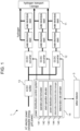
- FIG. 1 is a configuration diagram of a hydrogen producing system 1 according to an embodiment 1 of the present disclosure.
- a hydrogen producing system 1 is a system to produce hydrogen using AC (alternating current) electric power supplied by renewable energy or power transmission and distribution systems.
- the hydrogen producing system 1 produces hydrogen by operating water electrolysis stacks 11 using the supplied electric power.
- the hydrogen producing system 1 includes water electrolysis stack s11, a DC/DC converter 12, an AC/DC rectifier 13, a power distribution control system 14, and a defect detector 3.
- the water electrolysis stack 11 produces hydrogen by electrolyzing water.
- two water electrolysis stacks 11 are connected in series, and three pairs of the two water electrolysis stacks 11 as one pair are connected in parallel. Hydrogen produced by the water electrolysis stack 11 is outputted to the transport facility and to the storage facility.
- the AC/DC rectifier 13 converts the AC power supplied to the hydrogen producing system 1 to DC (direct current) power, and outputs the converted power to the DC/DC converter 12.
- the DC/DC converters 12 control the operational status of the water electrolysis stack 11 by providing electric power to the water electrolysis stack 11.
- the power distribution control system 14 controls the operational status of the water electrolysis stack 11 via the DC/DC converter 12 by outputting an operational command to the DC/DC converter 12.
- the power distribution control system 14 includes an operation plan formulator 141, a stack operation allocator 142, a power distribution commander 143, a deterioration characteristic data manager 144, and a deterioration rate estimator 145.
- the operation plan formulator 141 formulates an operation rotation plan for the water electrolysis stack 11.
- the operation rotation means an order by which any one of run prioritized stack / stop prioritized stack is allocated, which will be an operational status of each water electrolysis stack 11. Details of those prioritized stacks will be described later.
- the stack operation allocator 142 determines the operational state of each water electrolysis stack 11 according to the operation rotation plan established by the operation plan formulator 141.
- the power distribution commander 143 provides an electric current command to the DC/DC converters 12 such that the water electrolysis stack 11 operates in accordance with its allocated operating status.
- the deterioration characteristic data manager 144 has deterioration characteristic data describing the deterioration characteristic of the water electrolysis stack 11.
- the operation plan formulator 141 may formulate an operation rotation plan in accordance with this degradation characteristic.
- the deterioration rate estimator 145 estimates the deterioration rate of each water electrolytic stack 11 when it is assumed that the water electrolytic stack 11 is operated according to the plan.
- “Defect” in the water electrolysis stack 11 (or string) means being uncapable of exhibiting hydrogen producing capacity as defined in specification of the stack (or string).
- “Deterioration” is an example of cause of defect, and means that components or the like are worn out or modified of its characteristic due to the cumulative operation time. In general, it is assumed that ageing degradation occurs when the product continues to be used in a normal manner of use.
- “Failure” is also an example of cause of defect, and means an event that is not assumed as deterioration. Failure may occur suddenly rather than over time. Since the present disclosure is targeting defects caused by both deterioration and failure, "defect" is used below as a term including both of them.
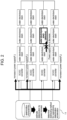
- FIG. 2 is a schematic diagram illustrating a procedure for controlling the electric power supply to each water electrolysis stack in the embodiment 1.
- a series connection of a plurality of water electrolysis stacks 11 is referred to as a string (serial unit).
- the power distribution control system 14 reduces the power supply to the strings (defective strings) containing the defective water electrolysis stack 11 (defective stacks) into a level lower than that of before the defect occurs. It is not always necessarily to stop the power supply. It is sufficient to at least reduce the power supply to a level lower than that of before the defect occurs.
- the power distribution control system 14 compensates for the reduced power supply to the defective string by increasing the power supply to the other strings.
- a defective stack occurs in the third string. Therefore, the power supply PI, P2, P4 for the first, second, and fourth strings (normal strings) are increased than before the defect occurs.
- simply increasing the power supply may promote degradation of the water electrolysis stack 11. Therefore, the power distribution control system 14 adjusts the amount of power supplied to each string (and thus each water electrolysis stack 11) so as to suppress the deterioration of the water electrolysis stack 11 as much as possible according to the deterioration characteristics.
- Figure 3 shows an example of increasing the power supply to a normal string. Now it is assumed that a defective stack has occurred in the third string as shown in Figure 2 . It is assumed that the strings were operating in a current density 1.5A/cm 2 at the normal state (prior to the occurrence of the defect).
- the distribution method (1) redistributes the electric power which was supplied to the third string equally to the first, second, and fourth strings.
- the current density supplied to each string prior to the defect was 1.5A/cm 2 .
- the current density supplied to each string after the defect is 2.0A/cm 2 .
- the distribution method (2) distributes the electric power which was supplied to the third string between the first, second, and fourth strings by operation rotation. The rotation is repeated such that, for example, one string bears all of the power of the third string in one period and then another string bears all of the power of the third string in the next period.
- the current densities supplied to the respective strings after the occurrence of the defect are 1.5 or 3.0A/cm 2 .
- the current density 1.5A/cm 2 corresponds to the "low distribution serial unit" and 3.0A/cm 2 corresponds to the "high distribution serial unit".
- the distribution method (3) performs rotation similarly to the distribution method (2). However, unlike the distribution method (2), any two or more strings jointly bear the power of the third string.
- the share of the load at each time point is distributed by rotation so that the sum of the load over a time period is equal among the strings.
- the current densities supplied to the respective strings after the occurrence of the defect are 1.5, 2.0, or 2.5A/cm 2 .
- the current density 1.5A/cm 2 corresponds to a "low distribution serial unit”.
- the current density 2.0 or 2.5A/cm 2 correspond to a "high distribution serial unit".
- the distribution method to be used can be determined according to the deterioration characteristics.
- the power distribution control system 14 estimates the future deterioration rate when executing these power distributions based on the deterioration characteristics, and selects the distribution pattern to minimize the deterioration rate.
- a calculation example of the degradation rate will be described using the degradation characteristic data described in Non-Patent Documents 1 to 3 as an example.
- Non-Patent Document 1 194mV/h
- 267mV/h 267mV/h
- Non-patent document 3 For the case of varying the current density as in the distribution method (2) (3), in Non-patent document 3, the operation of switching the current density between 2.5A/cm 2 and 1.0A/cm 2 every 6 hours is performed for about 300 hours, and then the operation of switching between 3.0A/cm 2 and 1.0A/cm 2 every 6 hours was performed for about 400 hours (i.e., a total of 700 hours operating). As a result, a value of the degradation rate of 63mV/h has been reported. This is a degradation rate of 1/3 or less of the distribution method (1).
- Non-Patent Document 3 Although the conditions of Non-Patent Document 3 are not the same as those of the distribution methods (2) (3), it is also reported in Non-Patent Document 2 that the deterioration rate can be more suppressed by dynamically changing the current density supplied to the water electrolysis stack rather than by making it constant. Therefore, the distribution methods (2) (3) are expected to have a lower degradation rate than the distribution method (1).
- the deterioration characteristic data describes the deterioration characteristic as described above.
- the power distribution control system 14 controls the power distribution in accordance with this degradation characteristic.
- the degradation characteristic data describes each combination of the current density and the switching interval thereof and the degradation rate, respectively.
- the power distribution control system 14 uses one of those combinations in which the degradation rate is assumed to be the smallest.
- a method of detecting a defect of the water electrolysis stack 11 will be described below.
- the defect detector 3 detects the defect of the water electrolytic stack 11 by monitoring these parameters.
- the following categories of cases may be used for supplying power to the defect stack.
- FIG 4 is a diagram showing another configuration example of the hydrogen producing system 1. As shown in Figure 4 , one DC/DC converter 12 may control more than one string. The number of strings controlled by one DC/DC converter 12 may be the same for all DC/DC converters 12 or may be different for each DC/DC converter 12.
- Figure 5 is an example of a user interface presented by the power distribution control system 14.
- the user interface may be presented, for example, as a screen interface shown on a display.
- the user interface may comprise, for example, a display screen and a control menu screen.
- Figure 5 shows a scene in which a menu for displaying the state of each stack/string is selected on the control menu.
- the power distribution control system 14 displays the location of the defective stack and the content of the defect on the display screen.
- the second water electrolysis stack 11 (# 5) of the string B is defective and that the voltage from the stack is abnormal.
- a "stop" button may cause the string to stop.
- string B has already stopped.
- the power distribution control system 14 displays a control menu on the control menu screen that can be selected by the user.
- the example of Figure 5 illustrates the following five menus: (a) presenting multiple combinations of power distribution for each string and the stack degradation rate due to the distribution; (b) presenting an optimal power distribution for each string based on the degradation prediction; (c) presenting a power plan to be used for hydrogen production in the future; (d) presenting power distribution for each string when maintaining or changing the power for hydrogen production in the event of a defect; (e) displaying the status of each stack/string.
- each functional unit When presenting the user interface, each functional unit operates as follows: (a) the degradation rate of the water electrolysis stack 11 is calculated by the degradation rate estimator 145 according to the degradation characteristics; (b) the power distribution for each string is determined by allocating the operation states of each water electrolysis stack 11 by the stack operation allocator according to the operation rotation established by the operation plan formulator 141.
- the hydrogen manufacturing system 1 controls the power distribution to each string on the basis of the deterioration prediction of the water electrolysis stack 11 calculated based on the location of the defective stack and the deterioration characteristics indicating the susceptibility for deterioration of the water electrolysis stack 11. Accordingly, even when a defective stack occurs, deterioration of the water electrolysis stack 11 can be effectively suppressed.
- the hydrogen producing system 1 adjusts the operation rotation so that one or more normal strings that do not include defective string share and bear the decrease in the power supply to the defective string. Accordingly, even when a defective stack occurs, it is possible to suppress the progress of the deterioration of a specific water electrolysis stack 11 only.
- the hydrogen producing system 1 when the degree of the defect of the defective stack is small, the power supply to the defective string is decreased from the normal state, and the amount of the decrease is shared by rotation among the normal strings. Accordingly, when the degree of defect is small, the defective string bears a certain amount of power, as well as the normal strings bear the decreased amount along with suppressing the deterioration using the operation rotation. Therefore, the deterioration progress of the defective string can be suppressed without excessively increasing the load on the normal string.
- the hydrogen producing system 1 adjusts the power distribution in accordance with the deterioration characteristics of the water electrolysis stack 11 (for example, the deterioration characteristics described together with the distribution methods (1), (2), and (3)) so that the deterioration of the defective string is suppressed more than the deterioration of the normal string. For example, the power supply amount for the defective string is reduced, and the reduced amount is borne by the operation rotation among the normal string. As a result, even when a defective stack occurs, it is possible to effectively suppress the deterioration of the water electrolysis stack 11 in accordance with the deterioration characteristics.
- the deterioration characteristics of the water electrolysis stack 11 for example, the deterioration characteristics described together with the distribution methods (1), (2), and (3)
- FIG. 6 is a configuration diagram of the hydrogen producing system 1 according to an embodiment 2 of the present disclosure.
- each water electrolysis stack 11 includes a switch 151.
- the switches 151 can individually turn ON/OFF the water electrolysis stacks 11.
- the water electrolysis stack 11 can be turned off by connecting the water electrolysis stack 11 and the switch 151 in parallel and by short-circuiting both ends of the water electrolysis stack 11 using the switch 151, for example. This is because a voltage is not applied to such water electrolysis stack 11.
- the switch 151 is controlled by a switch controller 146 provided in the power distribution control system 14.
- the power distribution control system 14 turns off only the defective stack by the switch 151.
- the other normal stacks in the defective string continue to operate in the same state as before the defect occurred. This reduces the power supply to the defective string by the amount that is no longer provided to the defective stack.
- the decreased power is borne by the normal strings by rotation in the same manner as in the embodiment 1. Compared with the embodiment 1, the increase in the power distribution to the normal string is smaller than that in the embodiment 1. Thus the deterioration progress of the normal string can be further suppressed.
- Figure 7 shows an example configuration including a diode 152 in addition to the switch 151.
- the diode 152 is provided for each of switch 151 and is serially connected (in parallel with water electrolysis stack 11) to switch 151.
- the voltage across the diode 152 when the switch 151 is closed (when the water electrolysis stack 11 is turned OFF) is configured to be approximately same as the voltage applied to the water electrolysis stack 11.
- the power distribution control system 14 turns off the defective stack by switch 151. At this time, the voltage that has been applied to the defective stack before the defect occurrence, is applied across the both ends of the diode 152. Thus the voltage applied to the other water electrolytic stack 11 in the defective string does not change. Accordingly, it is possible to suppress the fluctuation of the voltage applied to the other water electrolytic stack 11 in the defective string. However, the amount of hydrogen produced in the defective string is lower than before the occurrence of the defective string.
- soundness monitoring is a technique similar to defect detection, it can be distinguished as follows.
- the defect detection detects that the measured values such as the output voltage or output current of the water electrolytic stack 11 deviate from a specified range.
- soundness monitoring monitors the degree of degradation (or normality) of the water electrolysis stack 11 when the measured value falls within the normal range, according to how much the performance of the water electrolysis stack 11 is degraded from 100% soundness.
- the soundness of a string can be defined, for example, by the average soundness of the stacks belonging to that string.
- FIG 8 is a configuration diagram of the hydrogen producing system 1 according to the embodiment 3.
- the power distribution control system 14 in the embodiment 3 includes a soundness monitor 147.
- Other configurations are the same as those of the embodiments 1 to 2 ( Figure 8 shows a configuration example similar to that of the embodiment 1).
- the soundness monitor 147 monitors the soundness of the water electrolysis stack 11. Examples of the soundness include efficiency of hydrogen production (electrolysis efficiency). The value representing the soundness is normalized so that the new product has a soundness of 100%.
- the power distribution control system 14 determines the power distribution for a normal string according to the soundness level when a defective stack occurs.
- the power distribution borne by each normal string is equal when summing up the temporal change.
- the power distribution to strings having a high degree of soundness is made larger than the power distribution to strings having a low degree of soundness.
- the current densities borne by the fourth string may be 2.7A/cm 2 , for example, and the remaining 0.3A/cm 2 may be borne by first and second strings.
- the hydrogen producing system 1 according to the embodiment 3 proportionately allocates the power to the normal string at the time of occurrence of defect according to the soundness of the water electrolysis stack 11. Accordingly, the deterioration of the string having low soundness is suppressed, so that the deterioration progress of the normal string can be made uniform.
- FIG 9 is a configuration diagram of the hydrogen producing system 1 according to an embodiment 4 of the present disclosure.
- a management system 41 and a distributor 42 are provided.
- the management system 41 and the distributor 42 may be configured as a part of the hydrogen producing system 1, or may be configured as a functional unit separated from the hydrogen producing system 1.
- the distributor 42 switches the destination of the power generated by the renewable energy power generating facility 43 between being provided to the water electrolysis stack 11 and being sold to the consumer 44 (i.e., to output the received power to the transmission and distribution system).
- the management system 41 instructs to the distributor 42, for example, a distribution ratio between those options.
- the management system 41 further collects demand data for various types of energy (electric power, heat, hydrogen, etc.) from the consumer 44, and controls the energy distribution according to the data. For example, it is possible to perform control such as predicting the power demand and the spot price of energy reflecting the power demand, increasing the power selling ratio when the power demand is large, and producing hydrogen when the power demand is small.
- the supply amount of the energy may be similarly collected via related data, and the above control may be performed in accordance with the balance between the demand and the supply.
- the management system 41 may determine whether or not to maintain the amount of sold power between before and after the defect occurs, after estimating the penalty fee according to the regulation rules.
- the amount of electricity sold is maintained (i.e. when the amount of hydrogen produced is maintained), the amount of electricity sold is maintained as well as the deterioration of the water electrolysis stack 11 is suppressed by the operation rotation or the like described in the above embodiment.
- the management system 41 may determine whether to maintain the amount of hydrogen produced (i.e., whether to maintain the amount of electricity sold) in consideration of the degree of tightness of the demand with respect to the data on the supply and demand of hydrogen. For example, when a defective stack occurs, if the hydrogen demand is large, the hydrogen production amount is maintained as well as suppressing the deterioration of the water electrolysis stack 11 by the operation rotation or the like described in the above embodiment. Alternatively, if there arises a problem by decreasing the hydrogen production because of the nature of the consumer (e.g., when a certain degree of hydrogen is always required in the production plant), the distribution ratio is determined so as to maintain the hydrogen production amount. If the consumer has a hydrogen storage facility and can accept a certain amount of fluctuation in hydrogen production, the demand for maintaining hydrogen production is small. In view of these circumstances, the management system 41 may determine whether or not to maintain the hydrogen production amount.
- the present disclosure is not limited to the above-described embodiments, and various modifications are included.
- the above-described embodiments have been described in detail for the purpose of illustrating the present disclosure easily, and are not necessarily limited to those comprising all the described configurations. It is also possible to replace a part of the configuration of one embodiment with the configuration of another embodiment, and it is also possible to add the configuration of another embodiment to the configuration of one embodiment. Further, it is possible to add, delete, or replace a part of the configuration of each embodiment.
- Non-Patent Document 1 In the deterioration test of Non-Patent Document 1, it is described that a voltage of 1.4V or more is applied to the water electrolysis cell even when the current density is zero. This is slightly higher than the theoretical voltage of electrolysis of water (1.23V) and is a voltage value in the vicinity of the start of the electrolysis reaction. If the voltage is lowered to 0V during operation, reverse current may flow and the water electrolysis cell may be deteriorated. Therefore, in the present disclosure, DC/DC converters 12 are arranged at the entrances of the electric power paths supplied to the water electrolysis stack 11 so that voltages near the beginning of the electrolysis reactions can be applied to the water electrolysis stack 11 even when the electric current flowing through the water electrolysis stack 11 becomes zero. A similar role can be substituted by a power converter capable of outputting at least two or more types of voltages. Accordingly, such a power converter may be disposed instead of the DC/DC converter 12.
- the present disclosure is also applicable to a fuel cell which performs a reverse reaction from water electrolysis.
- the water electrolysis stack 11 is replaced by the fuel cell stack
- the power distribution control system 14 is replaced by the power generation sharing control system, and the flow of electric power and hydrogen are reversed from the present disclosure.
- the power distribution control system 14 and each functional unit thereof can be configured by hardware such as a circuit device in which these functions are implemented, or can be configured by software in which these functions are implemented being executed by a computing device such as a processor.
- a computing device such as a processor.
Landscapes
- Chemical & Material Sciences (AREA)
- Engineering & Computer Science (AREA)
- Organic Chemistry (AREA)
- Electrochemistry (AREA)
- Materials Engineering (AREA)
- Metallurgy (AREA)
- Chemical Kinetics & Catalysis (AREA)
- Automation & Control Theory (AREA)
- Analytical Chemistry (AREA)
- Inorganic Chemistry (AREA)
- Electrolytic Production Of Non-Metals, Compounds, Apparatuses Therefor (AREA)
- Supply And Distribution Of Alternating Current (AREA)
- Fuel Cell (AREA)
Applications Claiming Priority (1)
| Application Number | Priority Date | Filing Date | Title |
|---|---|---|---|
| JP2021133572A JP2023028092A (ja) | 2021-08-18 | 2021-08-18 | 水素製造システム、水素製造方法 |
Publications (3)
| Publication Number | Publication Date |
|---|---|
| EP4137609A2 true EP4137609A2 (de) | 2023-02-22 |
| EP4137609A3 EP4137609A3 (de) | 2023-03-15 |
| EP4137609B1 EP4137609B1 (de) | 2024-07-24 |
Family
ID=80448674
Family Applications (1)
| Application Number | Title | Priority Date | Filing Date |
|---|---|---|---|
| EP22158339.6A Active EP4137609B1 (de) | 2021-08-18 | 2022-02-23 | Wasserstofferzeugungssystem, verfahren zur produktion von wasserstoff |
Country Status (2)
| Country | Link |
|---|---|
| EP (1) | EP4137609B1 (de) |
| JP (1) | JP2023028092A (de) |
Cited By (1)
| Publication number | Priority date | Publication date | Assignee | Title |
|---|---|---|---|---|
| WO2026068184A1 (de) * | 2024-09-27 | 2026-04-02 | Quest One Gmbh | Verfahren zum betreiben einer wasserstoffproduktionsanlage und wasserstoffproduktionsanlage |
Families Citing this family (4)
| Publication number | Priority date | Publication date | Assignee | Title |
|---|---|---|---|---|
| WO2024236628A1 (ja) * | 2023-05-12 | 2024-11-21 | 株式会社日立製作所 | 制御システム及び制御方法、水素製造システム |
| JP7789842B2 (ja) * | 2024-05-21 | 2025-12-22 | 本田技研工業株式会社 | 電解システムの制御装置および電解システム |
| JP7673865B1 (ja) | 2024-07-31 | 2025-05-09 | 富士電機株式会社 | 水電解システム |
| JP7824471B1 (ja) * | 2025-05-28 | 2026-03-04 | 東京瓦斯株式会社 | 水電解方法 |
Citations (5)
| Publication number | Priority date | Publication date | Assignee | Title |
|---|---|---|---|---|
| JPS6058205B2 (ja) | 1981-12-21 | 1985-12-19 | 工業技術院長 | 低級オレフィンの製造方法 |
| JP2007031813A (ja) | 2005-07-29 | 2007-02-08 | Honda Motor Co Ltd | 水電解システム及びその運転方法 |
| JP2016518519A (ja) | 2013-03-19 | 2016-06-23 | シーメンス アクチエンゲゼルシヤフトSiemens Aktiengesellschaft | 電気分解スタックおよび電気分解装置 |
| JP2020196906A (ja) | 2019-05-30 | 2020-12-10 | 株式会社豊田中央研究所 | 水電解装置異常診断用プログラム及び水電解システム |
| JP2021023663A (ja) | 2019-08-07 | 2021-02-22 | Sanei株式会社 | 冷水排出装置 |
Family Cites Families (8)
| Publication number | Priority date | Publication date | Assignee | Title |
|---|---|---|---|---|
| JP2008066006A (ja) * | 2006-09-05 | 2008-03-21 | Matsushita Electric Ind Co Ltd | 燃料電池システム |
| FR2960559A1 (fr) * | 2010-05-28 | 2011-12-02 | Cie Europ Des Technologies De L Hydrogene | Installation de production d'hydrogene a haute disponibilite par electrolyse d'eau |
| US9917322B2 (en) * | 2015-07-01 | 2018-03-13 | The Boeing Company | Electrical power distribution system and method for a grid-tied reversible solid oxide fuel cell system |
| JP2018078669A (ja) * | 2016-11-07 | 2018-05-17 | パナソニックIpマネジメント株式会社 | 管理装置、及び発電システム |
| JP2018085861A (ja) * | 2016-11-24 | 2018-05-31 | 株式会社日立製作所 | 水素利用システムおよび統合エネルギシステム |
| JP6897250B2 (ja) * | 2017-04-07 | 2021-06-30 | 富士通株式会社 | 電解システム、電解制御装置及び電解システムの制御方法 |
| WO2021045017A1 (ja) * | 2019-09-06 | 2021-03-11 | 国立大学法人神戸大学 | 光分解モジュール、光分解セル、分解システム、生活環境持続システム、及び供給量調整システム |
| EP4074866B1 (de) * | 2019-12-09 | 2023-09-20 | Fujitsu Limited | Wasserelektrolysevorrichtung und wasserelektrolysesystem |
-
2021
- 2021-08-18 JP JP2021133572A patent/JP2023028092A/ja active Pending
-
2022
- 2022-02-23 EP EP22158339.6A patent/EP4137609B1/de active Active
Patent Citations (6)
| Publication number | Priority date | Publication date | Assignee | Title |
|---|---|---|---|---|
| JPS6058205B2 (ja) | 1981-12-21 | 1985-12-19 | 工業技術院長 | 低級オレフィンの製造方法 |
| JP2007031813A (ja) | 2005-07-29 | 2007-02-08 | Honda Motor Co Ltd | 水電解システム及びその運転方法 |
| JP4842577B2 (ja) | 2005-07-29 | 2011-12-21 | 本田技研工業株式会社 | 水電解システムの運転方法 |
| JP2016518519A (ja) | 2013-03-19 | 2016-06-23 | シーメンス アクチエンゲゼルシヤフトSiemens Aktiengesellschaft | 電気分解スタックおよび電気分解装置 |
| JP2020196906A (ja) | 2019-05-30 | 2020-12-10 | 株式会社豊田中央研究所 | 水電解装置異常診断用プログラム及び水電解システム |
| JP2021023663A (ja) | 2019-08-07 | 2021-02-22 | Sanei株式会社 | 冷水排出装置 |
Non-Patent Citations (3)
| Title |
|---|
| C. RAKOUSKY ET AL., ELECTROCHIMICA ACTA, vol. 278, 2018, pages 324 |
| C. RAKOUSKY ET AL., J. POWER SOURCES, vol. 342, 2017, pages 38 |
| S. FRENCH: "PhD Thesis", 2018, AALBORG UNIVERSITY, article "Lifetime investigation of PEM electrolyzers under realistic load profiles" |
Cited By (1)
| Publication number | Priority date | Publication date | Assignee | Title |
|---|---|---|---|---|
| WO2026068184A1 (de) * | 2024-09-27 | 2026-04-02 | Quest One Gmbh | Verfahren zum betreiben einer wasserstoffproduktionsanlage und wasserstoffproduktionsanlage |
Also Published As
| Publication number | Publication date |
|---|---|
| JP2023028092A (ja) | 2023-03-03 |
| EP4137609B1 (de) | 2024-07-24 |
| EP4137609A3 (de) | 2023-03-15 |
Similar Documents
| Publication | Publication Date | Title |
|---|---|---|
| EP4137609A2 (de) | Wasserstofferzeugungssystem, verfahren zur produktion von wasserstoff | |
| JP7699126B2 (ja) | 水素発生のためのモジュール式システムおよびその動作方法 | |
| Matayoshi et al. | Islanding operation scheme for DC microgrid utilizing pseudo Droop control of photovoltaic system | |
| Pelosi et al. | Battery-hydrogen vs. flywheel-battery hybrid storage systems for renewable energy integration in mini-grid: A techno-economic comparison | |
| US9303325B2 (en) | Power dispatch system for electrolytic production of hydrogen from wind power | |
| EP4234766A2 (de) | Wasserstoffherstellungssystem und wasserstoffherstellungsverfahren | |
| Valverde et al. | Definition, analysis and experimental investigation of operation modes in hydrogen-renewable-based power plants incorporating hybrid energy storage | |
| EP4239825A1 (de) | Verfahren zur steuerung der herstellung eines elektrolyseurs | |
| KR20210079261A (ko) | 배터리 전압 데이터를 이용한 이상 상태 사전 감지 시스템 | |
| EP4261325A2 (de) | Wasserstoffherstellungssystem, wasserstoffherstellungsverfahren | |
| US20240150909A1 (en) | Modular systems for hydrogen generation and methods of operating thereof | |
| KR101736717B1 (ko) | 에너지 저장 장치 및 그의 제어 방법 | |
| JP2016039721A (ja) | 直流配電システム | |
| KR20200005070A (ko) | 무정전 전력 공급 관리 시스템 | |
| KR102145323B1 (ko) | 분산전원 플랜트를 관리하기 위한 모니터링 시스템 및 방법 | |
| EP4283813A1 (de) | Wasserelektrolysesystem mit verwaltung der stromversorgung von erneuerbarer energie | |
| KR102210529B1 (ko) | Pms일체형 pcs가 구비된 ess 운용방법 | |
| KR20130077934A (ko) | 배터리 에너지 저장 시스템 | |
| KR102136504B1 (ko) | 무정전 전력 공급 관리 시스템 | |
| KR102703337B1 (ko) | 축전지 감시 시스템 및 축전지 감시 장치 | |
| CN114362154A (zh) | 基于协调控制的带储能系统的光伏电站运维方法及系统 | |
| US20190052095A1 (en) | Power management server, power management system, and power management method | |
| WO2024069801A1 (ja) | 制御装置、制御方法、水素製造システム及び電力・水素供給システム | |
| US20250253368A1 (en) | Method for controlling fuel cell device, control device, and fuel cell system | |
| Babaiahgari et al. | Coordinated control and optimization of DC power systems |
Legal Events
| Date | Code | Title | Description |
|---|---|---|---|
| PUAI | Public reference made under article 153(3) epc to a published international application that has entered the european phase |
Free format text: ORIGINAL CODE: 0009012 |
|
| STAA | Information on the status of an ep patent application or granted ep patent |
Free format text: STATUS: REQUEST FOR EXAMINATION WAS MADE |
|
| PUAL | Search report despatched |
Free format text: ORIGINAL CODE: 0009013 |
|
| 17P | Request for examination filed |
Effective date: 20220223 |
|
| AK | Designated contracting states |
Kind code of ref document: A2 Designated state(s): AL AT BE BG CH CY CZ DE DK EE ES FI FR GB GR HR HU IE IS IT LI LT LU LV MC MK MT NL NO PL PT RO RS SE SI SK SM TR |
|
| AK | Designated contracting states |
Kind code of ref document: A3 Designated state(s): AL AT BE BG CH CY CZ DE DK EE ES FI FR GB GR HR HU IE IS IT LI LT LU LV MC MK MT NL NO PL PT RO RS SE SI SK SM TR |
|
| RIC1 | Information provided on ipc code assigned before grant |
Ipc: C25B 15/02 20060101ALI20230207BHEP Ipc: C25B 15/023 20210101ALI20230207BHEP Ipc: C25B 9/70 20210101ALI20230207BHEP Ipc: C25B 1/04 20060101AFI20230207BHEP |
|
| GRAP | Despatch of communication of intention to grant a patent |
Free format text: ORIGINAL CODE: EPIDOSNIGR1 |
|
| STAA | Information on the status of an ep patent application or granted ep patent |
Free format text: STATUS: GRANT OF PATENT IS INTENDED |
|
| INTG | Intention to grant announced |
Effective date: 20240312 |
|
| GRAS | Grant fee paid |
Free format text: ORIGINAL CODE: EPIDOSNIGR3 |
|
| GRAA | (expected) grant |
Free format text: ORIGINAL CODE: 0009210 |
|
| STAA | Information on the status of an ep patent application or granted ep patent |
Free format text: STATUS: THE PATENT HAS BEEN GRANTED |
|
| AK | Designated contracting states |
Kind code of ref document: B1 Designated state(s): AL AT BE BG CH CY CZ DE DK EE ES FI FR GB GR HR HU IE IS IT LI LT LU LV MC MK MT NL NO PL PT RO RS SE SI SK SM TR |
|
| REG | Reference to a national code |
Ref country code: GB Ref legal event code: FG4D |
|
| REG | Reference to a national code |
Ref country code: CH Ref legal event code: EP |
|
| REG | Reference to a national code |
Ref country code: DE Ref legal event code: R096 Ref document number: 602022004696 Country of ref document: DE |
|
| REG | Reference to a national code |
Ref country code: IE Ref legal event code: FG4D |
|
| REG | Reference to a national code |
Ref country code: LT Ref legal event code: MG9D |
|
| REG | Reference to a national code |
Ref country code: NL Ref legal event code: MP Effective date: 20240724 |
|
| PG25 | Lapsed in a contracting state [announced via postgrant information from national office to epo] |
Ref country code: PT Free format text: LAPSE BECAUSE OF FAILURE TO SUBMIT A TRANSLATION OF THE DESCRIPTION OR TO PAY THE FEE WITHIN THE PRESCRIBED TIME-LIMIT Effective date: 20241125 |
|
| REG | Reference to a national code |
Ref country code: AT Ref legal event code: MK05 Ref document number: 1706395 Country of ref document: AT Kind code of ref document: T Effective date: 20240724 |
|
| PG25 | Lapsed in a contracting state [announced via postgrant information from national office to epo] |
Ref country code: NL Free format text: LAPSE BECAUSE OF FAILURE TO SUBMIT A TRANSLATION OF THE DESCRIPTION OR TO PAY THE FEE WITHIN THE PRESCRIBED TIME-LIMIT Effective date: 20240724 |
|
| PG25 | Lapsed in a contracting state [announced via postgrant information from national office to epo] |
Ref country code: PT Free format text: LAPSE BECAUSE OF FAILURE TO SUBMIT A TRANSLATION OF THE DESCRIPTION OR TO PAY THE FEE WITHIN THE PRESCRIBED TIME-LIMIT Effective date: 20241125 Ref country code: NL Free format text: LAPSE BECAUSE OF FAILURE TO SUBMIT A TRANSLATION OF THE DESCRIPTION OR TO PAY THE FEE WITHIN THE PRESCRIBED TIME-LIMIT Effective date: 20240724 |
|
| PG25 | Lapsed in a contracting state [announced via postgrant information from national office to epo] |
Ref country code: NO Free format text: LAPSE BECAUSE OF FAILURE TO SUBMIT A TRANSLATION OF THE DESCRIPTION OR TO PAY THE FEE WITHIN THE PRESCRIBED TIME-LIMIT Effective date: 20241024 |
|
| PG25 | Lapsed in a contracting state [announced via postgrant information from national office to epo] |
Ref country code: PL Free format text: LAPSE BECAUSE OF FAILURE TO SUBMIT A TRANSLATION OF THE DESCRIPTION OR TO PAY THE FEE WITHIN THE PRESCRIBED TIME-LIMIT Effective date: 20240724 Ref country code: FI Free format text: LAPSE BECAUSE OF FAILURE TO SUBMIT A TRANSLATION OF THE DESCRIPTION OR TO PAY THE FEE WITHIN THE PRESCRIBED TIME-LIMIT Effective date: 20240724 Ref country code: GR Free format text: LAPSE BECAUSE OF FAILURE TO SUBMIT A TRANSLATION OF THE DESCRIPTION OR TO PAY THE FEE WITHIN THE PRESCRIBED TIME-LIMIT Effective date: 20241025 |
|
| PG25 | Lapsed in a contracting state [announced via postgrant information from national office to epo] |
Ref country code: BG Free format text: LAPSE BECAUSE OF FAILURE TO SUBMIT A TRANSLATION OF THE DESCRIPTION OR TO PAY THE FEE WITHIN THE PRESCRIBED TIME-LIMIT Effective date: 20240724 |
|
| PG25 | Lapsed in a contracting state [announced via postgrant information from national office to epo] |
Ref country code: LV Free format text: LAPSE BECAUSE OF FAILURE TO SUBMIT A TRANSLATION OF THE DESCRIPTION OR TO PAY THE FEE WITHIN THE PRESCRIBED TIME-LIMIT Effective date: 20240724 |
|
| PG25 | Lapsed in a contracting state [announced via postgrant information from national office to epo] |
Ref country code: AT Free format text: LAPSE BECAUSE OF FAILURE TO SUBMIT A TRANSLATION OF THE DESCRIPTION OR TO PAY THE FEE WITHIN THE PRESCRIBED TIME-LIMIT Effective date: 20240724 Ref country code: IS Free format text: LAPSE BECAUSE OF FAILURE TO SUBMIT A TRANSLATION OF THE DESCRIPTION OR TO PAY THE FEE WITHIN THE PRESCRIBED TIME-LIMIT Effective date: 20241124 |
|
| PG25 | Lapsed in a contracting state [announced via postgrant information from national office to epo] |
Ref country code: HR Free format text: LAPSE BECAUSE OF FAILURE TO SUBMIT A TRANSLATION OF THE DESCRIPTION OR TO PAY THE FEE WITHIN THE PRESCRIBED TIME-LIMIT Effective date: 20240724 |
|
| PG25 | Lapsed in a contracting state [announced via postgrant information from national office to epo] |
Ref country code: ES Free format text: LAPSE BECAUSE OF FAILURE TO SUBMIT A TRANSLATION OF THE DESCRIPTION OR TO PAY THE FEE WITHIN THE PRESCRIBED TIME-LIMIT Effective date: 20240724 Ref country code: RS Free format text: LAPSE BECAUSE OF FAILURE TO SUBMIT A TRANSLATION OF THE DESCRIPTION OR TO PAY THE FEE WITHIN THE PRESCRIBED TIME-LIMIT Effective date: 20241024 |
|
| PG25 | Lapsed in a contracting state [announced via postgrant information from national office to epo] |
Ref country code: RS Free format text: LAPSE BECAUSE OF FAILURE TO SUBMIT A TRANSLATION OF THE DESCRIPTION OR TO PAY THE FEE WITHIN THE PRESCRIBED TIME-LIMIT Effective date: 20241024 Ref country code: PL Free format text: LAPSE BECAUSE OF FAILURE TO SUBMIT A TRANSLATION OF THE DESCRIPTION OR TO PAY THE FEE WITHIN THE PRESCRIBED TIME-LIMIT Effective date: 20240724 Ref country code: NO Free format text: LAPSE BECAUSE OF FAILURE TO SUBMIT A TRANSLATION OF THE DESCRIPTION OR TO PAY THE FEE WITHIN THE PRESCRIBED TIME-LIMIT Effective date: 20241024 Ref country code: LV Free format text: LAPSE BECAUSE OF FAILURE TO SUBMIT A TRANSLATION OF THE DESCRIPTION OR TO PAY THE FEE WITHIN THE PRESCRIBED TIME-LIMIT Effective date: 20240724 Ref country code: IS Free format text: LAPSE BECAUSE OF FAILURE TO SUBMIT A TRANSLATION OF THE DESCRIPTION OR TO PAY THE FEE WITHIN THE PRESCRIBED TIME-LIMIT Effective date: 20241124 Ref country code: HR Free format text: LAPSE BECAUSE OF FAILURE TO SUBMIT A TRANSLATION OF THE DESCRIPTION OR TO PAY THE FEE WITHIN THE PRESCRIBED TIME-LIMIT Effective date: 20240724 Ref country code: GR Free format text: LAPSE BECAUSE OF FAILURE TO SUBMIT A TRANSLATION OF THE DESCRIPTION OR TO PAY THE FEE WITHIN THE PRESCRIBED TIME-LIMIT Effective date: 20241025 Ref country code: FI Free format text: LAPSE BECAUSE OF FAILURE TO SUBMIT A TRANSLATION OF THE DESCRIPTION OR TO PAY THE FEE WITHIN THE PRESCRIBED TIME-LIMIT Effective date: 20240724 Ref country code: ES Free format text: LAPSE BECAUSE OF FAILURE TO SUBMIT A TRANSLATION OF THE DESCRIPTION OR TO PAY THE FEE WITHIN THE PRESCRIBED TIME-LIMIT Effective date: 20240724 Ref country code: BG Free format text: LAPSE BECAUSE OF FAILURE TO SUBMIT A TRANSLATION OF THE DESCRIPTION OR TO PAY THE FEE WITHIN THE PRESCRIBED TIME-LIMIT Effective date: 20240724 Ref country code: AT Free format text: LAPSE BECAUSE OF FAILURE TO SUBMIT A TRANSLATION OF THE DESCRIPTION OR TO PAY THE FEE WITHIN THE PRESCRIBED TIME-LIMIT Effective date: 20240724 |
|
| PG25 | Lapsed in a contracting state [announced via postgrant information from national office to epo] |
Ref country code: SM Free format text: LAPSE BECAUSE OF FAILURE TO SUBMIT A TRANSLATION OF THE DESCRIPTION OR TO PAY THE FEE WITHIN THE PRESCRIBED TIME-LIMIT Effective date: 20240724 Ref country code: DK Free format text: LAPSE BECAUSE OF FAILURE TO SUBMIT A TRANSLATION OF THE DESCRIPTION OR TO PAY THE FEE WITHIN THE PRESCRIBED TIME-LIMIT Effective date: 20240724 Ref country code: RO Free format text: LAPSE BECAUSE OF FAILURE TO SUBMIT A TRANSLATION OF THE DESCRIPTION OR TO PAY THE FEE WITHIN THE PRESCRIBED TIME-LIMIT Effective date: 20240724 |
|
| PG25 | Lapsed in a contracting state [announced via postgrant information from national office to epo] |
Ref country code: EE Free format text: LAPSE BECAUSE OF FAILURE TO SUBMIT A TRANSLATION OF THE DESCRIPTION OR TO PAY THE FEE WITHIN THE PRESCRIBED TIME-LIMIT Effective date: 20240724 |
|
| PG25 | Lapsed in a contracting state [announced via postgrant information from national office to epo] |
Ref country code: CZ Free format text: LAPSE BECAUSE OF FAILURE TO SUBMIT A TRANSLATION OF THE DESCRIPTION OR TO PAY THE FEE WITHIN THE PRESCRIBED TIME-LIMIT Effective date: 20240724 |
|
| REG | Reference to a national code |
Ref country code: DE Ref legal event code: R097 Ref document number: 602022004696 Country of ref document: DE |
|
| PG25 | Lapsed in a contracting state [announced via postgrant information from national office to epo] |
Ref country code: SK Free format text: LAPSE BECAUSE OF FAILURE TO SUBMIT A TRANSLATION OF THE DESCRIPTION OR TO PAY THE FEE WITHIN THE PRESCRIBED TIME-LIMIT Effective date: 20240724 Ref country code: IT Free format text: LAPSE BECAUSE OF FAILURE TO SUBMIT A TRANSLATION OF THE DESCRIPTION OR TO PAY THE FEE WITHIN THE PRESCRIBED TIME-LIMIT Effective date: 20240724 |
|
| PLBE | No opposition filed within time limit |
Free format text: ORIGINAL CODE: 0009261 |
|
| STAA | Information on the status of an ep patent application or granted ep patent |
Free format text: STATUS: NO OPPOSITION FILED WITHIN TIME LIMIT |
|
| 26N | No opposition filed |
Effective date: 20250425 |
|
| PG25 | Lapsed in a contracting state [announced via postgrant information from national office to epo] |
Ref country code: SE Free format text: LAPSE BECAUSE OF FAILURE TO SUBMIT A TRANSLATION OF THE DESCRIPTION OR TO PAY THE FEE WITHIN THE PRESCRIBED TIME-LIMIT Effective date: 20240724 |
|
| PG25 | Lapsed in a contracting state [announced via postgrant information from national office to epo] |
Ref country code: MC Free format text: LAPSE BECAUSE OF FAILURE TO SUBMIT A TRANSLATION OF THE DESCRIPTION OR TO PAY THE FEE WITHIN THE PRESCRIBED TIME-LIMIT Effective date: 20240724 |
|
| REG | Reference to a national code |
Ref country code: CH Ref legal event code: PL |
|
| PG25 | Lapsed in a contracting state [announced via postgrant information from national office to epo] |
Ref country code: LU Free format text: LAPSE BECAUSE OF NON-PAYMENT OF DUE FEES Effective date: 20250223 |
|
| PG25 | Lapsed in a contracting state [announced via postgrant information from national office to epo] |
Ref country code: CH Free format text: LAPSE BECAUSE OF NON-PAYMENT OF DUE FEES Effective date: 20250228 |
|
| REG | Reference to a national code |
Ref country code: BE Ref legal event code: MM Effective date: 20250228 |
|
| PG25 | Lapsed in a contracting state [announced via postgrant information from national office to epo] |
Ref country code: FR Free format text: LAPSE BECAUSE OF NON-PAYMENT OF DUE FEES Effective date: 20250228 |
|
| PG25 | Lapsed in a contracting state [announced via postgrant information from national office to epo] |
Ref country code: BE Free format text: LAPSE BECAUSE OF NON-PAYMENT OF DUE FEES Effective date: 20250228 |
|
| PG25 | Lapsed in a contracting state [announced via postgrant information from national office to epo] |
Ref country code: IE Free format text: LAPSE BECAUSE OF NON-PAYMENT OF DUE FEES Effective date: 20250223 |
|
| PGFP | Annual fee paid to national office [announced via postgrant information from national office to epo] |
Ref country code: GB Payment date: 20260224 Year of fee payment: 5 |
|
| PGFP | Annual fee paid to national office [announced via postgrant information from national office to epo] |
Ref country code: DE Payment date: 20260223 Year of fee payment: 5 |