EP4234471A1 - Construction elevator and method for extending main rope of construction elevator - Google Patents
Construction elevator and method for extending main rope of construction elevator Download PDFInfo
- Publication number
- EP4234471A1 EP4234471A1 EP20958614.8A EP20958614A EP4234471A1 EP 4234471 A1 EP4234471 A1 EP 4234471A1 EP 20958614 A EP20958614 A EP 20958614A EP 4234471 A1 EP4234471 A1 EP 4234471A1
- Authority
- EP
- European Patent Office
- Prior art keywords
- rope
- machine room
- main rope
- gripper
- pulley
- Prior art date
- Legal status (The legal status is an assumption and is not a legal conclusion. Google has not performed a legal analysis and makes no representation as to the accuracy of the status listed.)
- Pending
Links
Images






Classifications
-
- B—PERFORMING OPERATIONS; TRANSPORTING
- B66—HOISTING; LIFTING; HAULING
- B66B—ELEVATORS; ESCALATORS OR MOVING WALKWAYS
- B66B19/00—Mining-hoist operation
Definitions
- the present invention relates to a construction elevator and a method for extending the main rope of the construction elevator.
- a construction elevator has been proposed as an elevator that is provided in a building structure under construction so as to transport materials and people.
- a machine room unit having a hoisting machine, a control panel, and the like is raised according to the progress of the construction of the building structure, thereby expanding the range in which a car moves vertically, that is, the operable range.
- the work of extending a main rope connected to the car is also performed.
- Conventional construction elevators include, for example, one as disclosed in PTL 1.
- the main rope is gripped with a predetermined force by a gripping device in order to prevent the main rope from being drawn from a main rope reel against the intention of the operator under its own weight when raising the machine room unit. Then, by raising the machine room unit, the main rope slides on the gripping device and the main rope is extended.
- an object of the present invention is to provide a construction elevator that enables main rope extension work without damaging the main rope, and a method for extending the main rope of the construction elevator.
- this construction elevator includes a rope reel, an elevating body, a pulley, a first rope gripper, and a second rope gripper.
- a main rope is wound around the rope reel.
- the elevating body is wrapped with the main rope drawn from the rope reel, and moves vertically in a hoistway of a building structure.
- the pulley is disposed on the main rope between the rope reel and the elevating body and wrapped with the main rope drawn from the rope reel.
- the first rope gripper releasably grips the main rope on the rope reel side of the pulley.
- the second rope gripper releasably grips the main rope on the elevating body side of the pulley.
- the pulley is supported so as to be movable along the direction in which the elevating body moves vertically.
- a method for extending the main rope of the construction elevator having the above-described configuration includes the following steps (1) to (4):
- the machine room unit can be easily installed without damaging the main rope.
- FIGS. 1 to 12 a construction elevator and a method for extending a main rope according to embodiments will be described with reference to FIGS. 1 to 12 .
- common members are denoted by the same reference signs.
- FIG. 1 is a schematic configuration diagram illustrating the construction elevator according to the present example.
- the elevator illustrated in FIG. 1 is a construction elevator that is provided in a building structure under construction and used for transporting materials and people.
- a construction elevator 1 is equipped with a support member 2 disposed at the top of a hoistway 100 of the building structure, a machine room unit 3, and a lifting device 6 for lifting the machine room unit 3.
- the construction elevator 1 is also equipped with a hoisting machine 9, a main rope 10, a car 11 on which people and materials are loaded, and a counterweight 12.
- the car 11 and the counterweight 12 illustrate examples of elevating bodies. Note that the positional relationship between the car 11 and the counterweight 12 may be reversed. That is, in FIG. 1 , the counterweight may correspond to reference sign 11, and the car may correspond to reference sign 12.
- the direction in which the car 11 and the counterweight 12 serving as elevating bodies move vertically is defined as the vertical direction.
- a car-side pulley 11a is provided at the top of the car 11.
- a weight-side pulley 12a is provided at the top of the counterweight 12.
- the main rope 10 is wrapped around the car-side pulley 11a and the weight-side pulley 12a.
- the main rope 10 is also wrapped around the sheave of the hoisting machine 9 installed in the machine room unit 3 to be described later.
- the main rope 10 is wound around a rope reel 15 provided in the machine room unit 3 to be described later, and is drawn from the rope reel 15. Furthermore, the end of the main rope 10 on the opposite side from the rope reel 15 is fixed to a rope-fixing portion 14 in the machine room unit 3. Furthermore, the main rope 10 is wrapped from the rope reel 15, through a pulley 19 to be described later, to the weight-side pulley 12a, the hoisting machine 9, and the car-side pulley 11a in this order, and the end of the main rope 10 is fixed to the rope-fixing portion 14. Then, when the hoisting machine 9 is driven, the car 11 and the counterweight 12 move vertically in the hoistway 100.
- the support member 2 is installed on a beam 101a provided at the uppermost portion of the hoistway 100 or a recess provided in the wall surface of the hoistway 100.
- the lifting device 6 is provided to the support member 2.
- the machine room unit 3 is disposed below support member 2 in the vertical direction. Furthermore, the machine room unit 3 is suspended from the support member 2 with the lifting device 6 therebetween.
- the machine room unit 3 is supported by the lifting device 6 so as to be liftable (movable).
- the lifting device 6 may be provided in a first machine room 4 and a second machine room 5 of the machine room unit 3 to be described later, and the lifting rope of the lifting device 6 may be provided in the support member 2.
- the machine room unit 3 has the first machine room 4 and the second machine room 5.
- the first machine room 4 is disposed below the second machine room 5 in the vertical direction.
- the first machine room 4 and the second machine room 5 are separably coupled, and are each independently lifted by the lifting device 6.
- a movable support mechanism 7 is provided at the bottom of the first machine room 4 in the vertical direction.
- the movable support mechanism 7 is configured so as to be stretchable from the first machine room 4 toward the wall surface of the hoistway 100. Furthermore, the movable support mechanism 7 is placed on beams 101b, 101c, and 101d provided in the hoistway 100 or a recess provided in the wall surface of the hoistway 100.
- the movable support mechanism 7 supports the machine room unit 3 or the first machine room 4 at a predetermined position in the hoistway 100.
- the movable support mechanism 7 is not limited to the above-described one, and various other fixing mechanisms, such as an engaging member that engages with a guide rail for supporting the car 11 in a vertically movable manner or the wall surface of the hoistway 100, and a fastening member that is fastened to the wall surface, may be applied.
- the first machine room 4 has an upper machine room 4a and a lower machine room 4b.
- the upper machine room 4a is installed at the top of the lower machine room 4b in the vertical direction.
- the second machine room 5 is installed at the top of the upper machine room 4a in the vertical direction.
- the hoisting machine 9 is installed in the lower machine room 4b.
- the rope-fixing portion 14 for fixing the end of the main rope 10 is installed in the lower machine room 4b.
- the configuration in which the first machine room 4 is divided into two, the upper machine room 4a and the lower machine room 4b has been described.
- the first machine room 4 may be a single machine room or may be divided into three or more machine rooms.
- the second machine room 5 is described as a single machine room, but may be divided into two or more machine rooms similarly to the first machine room 4.
- the rope reel 15 around which the main rope 10 is wound, a first rope gripper 16, a second rope gripper 17, and a deflector 22 are installed.
- the main rope 10 for extension is wound around the rope reel 15. Then, when raising the machine room unit 3, the main rope 10 for extension is drawn from the rope reel 15.
- the rope reel 15 is installed in the machine room unit 3, but the present invention is not limited thereto, and the rope reel 15 may be installed in a pit 100b, which is the bottom of the hoistway 100, or outside the hoistway 100.
- the deflector 22 is disposed near the rope reel 15.
- the deflector 22 changes the direction of the main rope 10 drawn from the rope reel 15 to the direction toward the second machine room 5.
- the first rope gripper 16 is provided near the deflector 22 and the rope reel 15.
- the first rope gripper 16 releasably grips the main rope 10, the direction of which has been changed by the deflector 22.
- the first rope gripper 16 grips the main rope 10 on the rope reel side (hereinafter, simply referred to as the "first side") A of the pulley 19 to be described later in the main rope 10.
- the first rope gripper 16 grips the main rope 10, thereby restricting the movement of the main rope 10.
- the first rope gripper 16 may be provided to the rope reel 15 or the deflector 22.
- the second rope gripper 17 is disposed on the main rope 10 on the elevating body side, that is, the counterweight 12 and car 11 side (hereinafter, simply referred to as the "second side") B, of the pulley 19 to be described later.
- the second rope gripper 17 has a grip portion 17a and a rope drum 17b.
- the grip portion 17a releasably grips the main rope 10.
- the grip portion 17a grips the main rope 10, thereby restricting the movement of the main rope 10.
- the rope drum 17b is disposed above the grip portion 17a in the vertical direction. Furthermore, the rope drum 17b is disposed closer to the pulley 19 than the grip portion 17a. Therefore, the grip portion 17a is disposed closer to the elevating body side than the rope drum 17b, that is, closer to the counterweight 12 and car 11 side.
- the rope drum 17b is supported in such a manner that the rotation thereof can be locked and released.
- the rope drum 17b is wrapped with N or more turns (N is 1 or more) of the main rope 10. When the rotation of the rope drum 17b is locked, frictional force is generated between the rope drum 17b and the main rope 10.
- the first machine room 4 has the two-story structure of the upper machine room 4a and the lower machine room 4b, so that the horizontal space in the hoistway 100 can be reduced.
- the first machine room 4 is not limited to the two-story structure of the upper machine room 4a and the lower machine room 4b, but may have a single-story structure in which the hoisting machine 9, the rope-fixing portion 14, the rope reel 15, the first rope gripper 16, and the second rope gripper 17 are installed in a single machine room.
- the second machine room 5 is separably coupled to the top of the upper machine room 4a in the first machine room 4.
- a control panel 8 that controls the hoisting machine 9, the car 11, and the like, the pulley 19, and a third rope gripper 18 are installed.
- the control panel 8 and the car 11 are electrically connected through a tail cord 13.
- a tail cord reel 20 is installed near the control panel 8.
- the tail cord 13 for extension is wound around the tail cord reel 20. Then, when raising the second machine room 5, the tail cord 13 is drawn from the tail cord reel 20.
- the pulley 19 is rotatably supported in the second machine room 5.
- the pulley 19 is disposed between the rope reel 15, and the car 11 and counterweight 12 that represent the elevating bodies.
- the main rope 10 drawn from the rope reel 15 is wrapped around the pulley 19. Furthermore, the pulley 19 changes the direction in which the main rope 10 extends from up to down.
- the third rope gripper 18 is disposed near the pulley 19.
- the third rope gripper 18 is disposed on the main rope 10 on the second side B of the pulley 19.
- the third rope gripper 18 is disposed closer to the pulley 19 than the rope drum 17b of the second rope gripper 17.
- the third rope gripper 18 releasably grips the main rope 10.
- the third rope gripper 18 operates to grip the main rope 10, and the first rope gripper 16 and the grip portion 17a of the second rope gripper 17 are released. Therefore, one end of the main rope 10 is fixed to the rope-fixing portion 14, and the other end of the main rope 10 is fixed to the third rope gripper 18.
- the rope drum 17b of the second rope gripper 17 is non-rotatably fixed.
- the frictional force generated between the rope drum 17b and the main rope 10 can reduce the load applied to the third rope gripper 18.
- the force (gripping force) with which the third rope gripper 18 grips the main rope 10 can be reduced, and damage to the main rope 10 due to the gripping of the third rope gripper 18 can be suppressed.
- the gripping force of the third rope gripper 18 can be reduced.
- the third rope gripper 18 grips the main rope 10 to fix the other end of the main rope 10, but the present invention is not limited thereto.
- the third rope gripper 18 may be released, the main rope 10 may be gripped by the first rope gripper 16, and the other end of the main rope 10 may be fixed by the first rope gripper 16.
- the other end of the main rope 10 is fixed by gripping the main rope 10 between the rope drum 17b of the second rope gripper 17 and the rope reel 15. Therefore, the other end of the main rope 10 may be fixed at the rope reel 15.
- FIGS. 2 to 4 are explanatory diagrams illustrating a method for extending the main rope 10.
- the car 11 and the first machine room 4 are coupled by a chain 201, and the car 11 is fixed.
- the counterweight 12 is lowered to the pit 100b, and the counterweight 12 is placed on a buffer (not illustrated) installed in the pit 100b.
- tension from the car 11 and the counterweight 12 is not applied to the main rope 10.
- the main rope 10 is gripped by the grip portion 17a of the second rope gripper 17, and the gripping of the main rope 10 by the third rope gripper 18 is released. Note that if the first rope gripper 16 is gripping the main rope 10, the gripping of the main rope 10 by the first rope gripper 16 is released. Then the first machine room 4 and the second machine room 5 are divided.
- the lifting device 6 coupled to the second machine room 5 is operated to raise only the second machine room 5 to a predetermined height (the beam 101b in the example illustrated in FIG. 2 ).
- a predetermined height the beam 101b in the example illustrated in FIG. 2 .
- the length (height) for raising the second machine room 5 only needs to be about half the length of the extension of the main rope 10.
- the pulley 19 provided in the second machine room 5 also rises.
- the lifting device 6 is stopped, and the second machine room 5 and the pulley 19 are temporarily fixed using the lifting device 6, a second machine room support mechanism (not illustrated), or the like.
- one end of the main rope 10 is fixed by the grip portion 17a of the second rope gripper 17, but the other end of the main rope 10, that is, the rope reel 15 side, is not fixed. Therefore, as the second machine room 5 and the pulley 19 rise, the main rope 10 on the rope reel 15 side is pulled, and the main rope 10 for extension is drawn from the rope reel 15. Thus, the raising operation of the second machine room 5 and the pulley 19 and the operation of drawing out the main rope 10 from the rope reel 15 can be performed simultaneously.
- the main rope 10 is gripped by the first rope gripper 16, and the gripping of the main rope 10 by the grip portion 17a of the second rope gripper 17 is released.
- the fixing of the rope drum 17b of the second rope gripper 17 is released, thereby allowing the rope drum 17b to rotate. Therefore, one end of the main rope 10 is fixed to the rope-fixing portion 14, and the other end of the main rope 10 is fixed to the first rope gripper 16.
- the movable support mechanism 7 is retracted to release the support of the first machine room 4 by the movable support mechanism 7. Then the lifting device 6 coupled to the first machine room 4 is operated to raise the first machine room 4 to a predetermined height (the beam 101c in the example illustrated in FIGS. 3 and 4 ). Thus, the main rope 10 for extension drawn from the rope reel 15 in the operation illustrated in FIG. 2 is sent out toward the counterweight 12 and car 11 side through the pulley 19 and the second rope gripper 17.
- the lifting device 6 When the first machine room 4 rises to the predetermined height, the lifting device 6 is stopped. Then, as illustrated in FIG. 4 , the movable support mechanism 7 is extended to place the movable support mechanism 7 on the beam 101c. In addition, the first machine room 4 and the second machine room 5 are coupled. Thus, the machine room unit 3, which is composed of the first machine room 4 and the second machine room 5, can be raised to the predetermined height.
- the rotation of the rope drum 17b of the second rope gripper 17 is locked, and the main rope 10 is gripped by the third rope gripper 18.
- the main rope 10 is first gripped by the grip portion 17a of the second rope gripper 17.
- the weight of the main rope 10 is not applied to the rope drum 17b of the second rope gripper 17, so that the rope drum 17b can be easily rotated, and the work of adjusting the phase of the rope drum 17b can be easily performed.
- the work of adjusting the phase of the rope drum 17b is completed, the rotation of the rope drum 17b is locked.
- the main rope 10 is gripped by the third rope gripper 18. Thereafter, the gripping of the main rope 10 by the grip portion 17a of the second rope gripper 17 is released. As described above, the main rope 10 is once gripped by the grip portion 17a of the second rope gripper 17, whereby it is possible to prevent the counterweight 12 from falling or the main rope 10 from falling under its own weight.
- the main rope 10 can be extended without sliding the main rope 10 on the rope grippers 16 and 18 and the grip portion 17a.
- wear of the main rope 10 can be prevented, and the gripping force of the rope grippers 16 and 18 and the grip portion 17a can be easily adjusted.
- the machine room unit 3 is divided into the first machine room 4 and the second machine room 5, each of which is independently lifted.
- the weight applied to the lifting device 6 can be reduced, and the lifting device 6 can be prevented from increasing in size.
- FIG. 5 is a schematic configuration diagram illustrating the construction elevator according to the second embodiment
- FIGS. 6 and 7 illustrate a method for extending the main rope of the construction elevator according to the second embodiment.
- the construction elevator according to the second embodiment is different from the construction elevator 1 according to the first embodiment in the configuration of the machine room unit. Therefore, here, the same reference signs are given to portions common to the construction elevator 1 according to the first embodiment, and redundant description will be omitted.
- a construction elevator 1B has a machine room unit 3B composed of a first machine room 4B and a second machine room 5B.
- the hoisting machine 9 the rope-fixing portion 14 for fixing the end of the main rope 10, the rope reel 15, the first rope gripper 16, and a second rope gripper 27 are installed.
- the control panel 8, the tail cord reel 20, and the pulley 19 are installed.
- the second machine room 5B is disposed above the first machine room 4B in the vertical direction. Furthermore, similarly to the first machine room 4B, a movable support mechanism 21 is provided in the second machine room 5B.
- the movable support mechanism 21 is configured so as to be stretchable from the second machine room 5B toward the wall surface of the hoistway 100. Furthermore, the movable support mechanism 21 is placed on the beams 101b, 101c, and 101d provided in the hoistway 100 or a recess provided in the wall surface of the hoistway 100.
- the movable support mechanism 21 supports the machine room unit 3 or the second machine room 5B at a predetermined position in the hoistway 100.
- the third rope gripper 18 is not provided in the second machine room 5B according to the second embodiment.
- the second rope gripper 27 has a lower grip portion 27a, a rope drum 27b, and an upper grip portion 27c. Since the configurations of the lower grip portion 27a and the rope drum 27b are similar to those of the grip portion 17a and the rope drum 17b of the second rope gripper 17 according to the first embodiment, the description thereof will be omitted.
- the upper grip portion 27c is disposed above the rope drum 27b in the vertical direction. That is, the upper grip portion 27c is disposed closer to the pulley 19 than the rope drum 27b. Similarly to the first rope gripper 16 and the lower grip portion 27a, the upper grip portion 27c releasably grips the main rope 10.
- the upper grip portion 27c has similar operation and effect to the third rope gripper 18 according to the first embodiment.
- the upper grip portion 27c of the second rope gripper 27 operates to grip the main rope 10, and the first rope gripper 16 and the lower grip portion 27a of the second rope gripper 27 are released. Therefore, one end of the main rope 10 is fixed to the rope-fixing portion 14, and the other end of the main rope 10 is fixed to the upper grip portion 27c of the second rope gripper 27.
- the upper grip portion 27c of the second rope gripper 27 may be released, the main rope 10 may be gripped by the first rope gripper 16, and the other end of the main rope 10 may be fixed by the first rope gripper 16.
- the car 11 and the first machine room 4 are coupled by the chain 201, and the car 11 is fixed.
- the counterweight 12 is lowered to the pit 100b, and the counterweight 12 is placed on a buffer (not illustrated) installed in the pit 100b.
- the movable support mechanism 21 is retracted to release the support of the second machine room 5B by the movable support mechanism 21.
- the lifting device 6 coupled to the second machine room 5B is operated to raise only the second machine room 5B to a predetermined height (the beam 101b in the example illustrated in FIG. 2 ) .
- the pulley 19 provided in the second machine room 5B also rises.
- the hoisting machine 9 can be driven to use the car 11. That is, the construction elevator 1B can be moved even during the work of extending the main rope 10, thereby allowing an improvement in the work of installing the construction elevator 1B and building structure construction work.
- the other end of the main rope 10 may be fixed by the lower grip portion 27a of the second rope gripper 27 provided in the first machine room 4B. Also in this case, the main rope 10 is not drawn vertically downward from the first machine room 4B.
- the main rope 10 is gripped by the first rope gripper 16, and the gripping of the main rope 10 by the upper grip portion 27c of the second rope gripper 27 is released.
- the fixing of the rope drum 27b of the second rope gripper 27 is released, thereby allowing, the rope drum 27b to rotate. Therefore, one end of the main rope 10 is fixed to the rope-fixing portion 14, and the other end of the main rope 10 is fixed to the first rope gripper 16.
- the movable support mechanism 7 is retracted to release the support of the first machine room 4B by the movable support mechanism 7. Then the lifting device 6 coupled to the first machine room 4B is operated to raise the first machine room 4B to a predetermined height (the beam 101c in the example illustrated in FIG. 7 ). Then, when the first machine room 4B is raised to the predetermined height, the lifting device 6 is stopped, and the movable support mechanism 7 is extended to place the movable support mechanism 7 on the beam 101c. Thus, the first machine room 4B and the second machine room 5B can be raised to the predetermined height.
- a predetermined height the beam 101c in the example illustrated in FIG. 7
- the rotation of the rope drum 27b of the second rope gripper 27 is locked, and the main rope 10 is gripped by the upper grip portion 27c.
- the main rope 10 is first gripped by the lower grip portion 27a of the second rope gripper 27. Then the phase of the rope drum 27b is adjusted, and the rotation of the rope drum 27b is locked.
- the main rope 10 is gripped by the upper grip portion 27c. Thereafter, the gripping of the main rope 10 by the lower grip portion 27a is released.
- the other configurations are similar to those of the construction elevator 1 according to the first embodiment, and thus the description thereof will be omitted.
- the construction elevator 1B according to the second embodiment can also provide similar operational effects to those of the construction elevator 1 according to the first embodiment described above.
- FIG. 8 is a schematic configuration diagram illustrating the construction elevator according to the third embodiment
- FIGS. 9 and 10 illustrate a method for extending the main rope of the construction elevator according to the third embodiment.
- the construction elevator according to the third embodiment is different from the construction elevator 1 according to the first embodiment in the configuration of the machine room unit. Therefore, here, the same reference signs are given to portions common to the construction elevator 1 according to the first embodiment, and redundant description will be omitted.
- a construction elevator 1C has a machine room unit 3C composed of a first machine room 4C and a second machine room 5C, and a pulley 19C.
- the first machine room 4C and the second machine room 5C are integrally formed.
- the hoisting machine 9 the rope-fixing portion 14 for fixing the end of the main rope 10, the rope reel 15, the first rope gripper 16, and the second rope gripper 17 are installed.
- the control panel 8, the tail cord reel 20, and the third rope gripper 18 are installed.
- the pulley 19C is supported by a pulley lifting device 6C so as to be liftable (movable) along the vertical direction. That is, the pulley 19C is moved independently from the machine room unit 3C by the pulley lifting device 6C.
- the pulley 19C is rotatably supported, and the main rope 10 is wrapped therearound.
- the first rope gripper 16 is disposed on the main rope 10 on the rope reel 15 side, that is, the first side A, of the pulley 19C.
- the second rope gripper 17 and the third rope gripper 18 are arranged on the main rope on the counterweight 12 and car 11 side, that is, the second side B, of the pulley 19C.
- the third rope gripper 18 operates to grip the main rope 10, and the first rope gripper 16 and the grip portion 17a of the second rope gripper 17 are released. Therefore, one end of the main rope 10 is fixed to the rope-fixing portion 14, and the other end of the main rope 10 is fixed to the third rope gripper 18. In addition, since the rope drum 17b of the second rope gripper 17 is non-rotatably fixed, the load applied to the third rope gripper 18 can be reduced.
- the third rope gripper 18 may be released, the main rope 10 may be gripped by the first rope gripper 16, and the other end of the main rope 10 may be fixed by the first rope gripper 16.
- the car 11 and the machine room unit 3C are coupled by the chain 201, and the car 11 is fixed.
- the counterweight 12 is lowered to the pit 100b, and the counterweight 12 is placed on a buffer (not illustrated) installed in the pit 100b.
- the pulley lifting device 6C coupled to the pulley 19C is driven to raise only the pulley 19C to a predetermined height.
- the main rope 10 on the second side B of the pulley 19C is fixed by the third rope gripper 18. Therefore, the main rope 10 can be drawn from the rope reel 15 by raising the pulley 19C.
- the length (height) for raising the pulley 19C only needs to be about half the length of the extension of the main rope 10.
- the present invention is not limited to this.
- the third rope gripper 18 may be released, and the main rope 10 may be fixed by the grip portion 17a of the second rope gripper 17.
- the pulley 19C is raised to the predetermined height, the lifting device 6 is stopped and the pulley 19C is temporarily fixed in the hoistway 100.
- the car 11 and the machine room unit 3C are coupled and the counterweight 12 is placed on the buffer, but the present invention is not limited thereto.
- one end of the main rope 10 on the second side B during the raising operation of the pulley 19C is fixed to the rope-fixing portion 14, and the other end thereof on the second side B is fixed to the third rope gripper 18. Therefore, even during the movement of the pulley 19C, it is not necessary to couple the car 11 to the machine room unit 3C and place the counterweight 12 on the buffer. Furthermore, even during the movement of the pulley 19C, the hoisting machine 9 may be driven to use the car 11.
- the main rope 10 is gripped by the first rope gripper 16, and the gripping of the main rope 10 by the third rope gripper 18 is released.
- the fixing of the rope drum 17b of the second rope gripper 17 is released, thereby allowing the rope drum 17b to rotate. Therefore, one end of the main rope 10 is fixed to the rope-fixing portion 14, and the other end of the main rope 10 is fixed to the first rope gripper 16.
- the movable support mechanism 7 is retracted to release the support of the machine room unit 3C by the movable support mechanism 7. Then the lifting device 6 coupled to the machine room unit 3C is operated to raise the machine room unit 3C to a predetermined height. Then, when the machine room unit 3C is raised to the predetermined height, the lifting device 6 is stopped, and the movable support mechanism 7 is extended to place the movable support mechanism 7 on the beam 101c. Thus, the machine room unit 3C can be raised to the predetermined height.
- the rotation of the rope drum 17b of the second rope gripper 17 is locked, and the main rope 10 is gripped by the third rope gripper 18.
- the main rope 10 is first gripped by the grip portion 17a of the second rope gripper 17. Then the phase of the rope drum 17b is adjusted, and the rotation of the rope drum 17b is locked.
- the main rope 10 is gripped by the third rope gripper 18. Thereafter, the gripping of the main rope 10 by the grip portion 17a of the second rope gripper 17 is released.
- the other configurations are similar to those of the construction elevator 1 according to the first embodiment, and thus the description thereof will be omitted.
- the construction elevator 1C according to the third embodiment can also provide similar operational effects to those of the construction elevator 1 according to the first embodiment described above.
- the pulley 19 rises together with the second machine room 5, 5B, so that the main rope 10 is drawn from the rope reel 15. That is, in the construction elevator 1 according to the first embodiment and the construction elevator 1B according to the second embodiment, the lifting device 6 for lifting the machine room unit 3, 3B serves as a pulley lifting device. Meanwhile, in the construction elevator 1C according to the third embodiment, only the pulley 19C rises independently of the machine room unit 3C, so that the main rope 10 is drawn from the rope reel 15.
- FIG. 11 is a schematic configuration diagram illustrating the construction elevator according to the fourth embodiment.
- the construction elevator according to the fourth embodiment is different from the construction elevators according to the first and third embodiments in the order in which the main rope is looped over the car and the counterweight. Therefore, here, the same reference signs are given to portions common to the construction elevators 1 and 1C according to the first and third embodiments, and redundant description will be omitted.
- a construction elevator 1D has a machine room unit 3D, the car 11, and the counterweight 12.
- the rope reel 15 around which the main rope 10 is wound, the hoisting machine 9, and the like are arranged in the machine room unit 3D.
- the main rope 10 is wrapped from the rope reel 15, through the pulley 19, to the car-side pulley 11a provided on the car 11, the hoisting machine 9, and the weight-side pulley 12a provided on the counterweight 12, in this order. Furthermore, one end of the main rope 10 extending from the weight-side pulley 12a is fixed to the rope-fixing portion 14 of the machine room unit 3D.
- the other configurations are similar to those of the construction elevators 1 and 1C according to the first and third embodiments, and thus the description thereof will be omitted.
- the construction elevator 1D according to the fourth embodiment can also provide similar operational effects to those of the construction elevators 1 and 1C according to the first and third embodiments described above.
- FIG. 12 is a schematic configuration diagram illustrating the construction elevator according to the fifth embodiment.
- the construction elevator according to the fifth embodiment is different from the construction elevator according to the second embodiment in the order in which the main rope is looped over the car and the counterweight. Therefore, here, the same reference signs are given to portions common to the construction elevator 1B according to the second embodiment, and redundant description will be omitted.
- a construction elevator 1E has a machine room unit 3E, the car 11, and the counterweight 12.
- the rope reel 15 around which the main rope 10 is wound, the hoisting machine 9, and the like are arranged in the machine room unit 3E.
- the main rope 10 is wound from the rope reel 15, through the pulley 19, to the car-side pulley 11a provided on the car 11, the hoisting machine 9, and the weight-side pulley 12a provided on the counterweight 12, in this order. Furthermore, .one end of the main rope 10 extending from the weight-side pulley 12a is fixed to the rope-fixing portion 14 of the machine room unit 3E.
- the other configurations are similar to those of the construction elevator 1B according to the second embodiment, and thus the description thereof will be omitted.
- the construction elevator 1E according to the fifth embodiment can also provide similar operational effects to as the construction elevator 1B according to the second embodiment described above.
Landscapes
- Lift-Guide Devices, And Elevator Ropes And Cables (AREA)
- Types And Forms Of Lifts (AREA)
Abstract
Description
- The present invention relates to a construction elevator and a method for extending the main rope of the construction elevator.
- In recent years, a construction elevator has been proposed as an elevator that is provided in a building structure under construction so as to transport materials and people. In this construction elevator, a machine room unit having a hoisting machine, a control panel, and the like, is raised according to the progress of the construction of the building structure, thereby expanding the range in which a car moves vertically, that is, the operable range. In addition, as the vertical movement range of the car is expanded, the work of extending a main rope connected to the car is also performed.
- Conventional construction elevators include, for example, one as disclosed in
PTL 1. In the technology disclosed inPTL 1, the main rope is gripped with a predetermined force by a gripping device in order to prevent the main rope from being drawn from a main rope reel against the intention of the operator under its own weight when raising the machine room unit. Then, by raising the machine room unit, the main rope slides on the gripping device and the main rope is extended. - PTL 1:
JP 2001-287881 A - However, in the technology disclosed in
PTL 1, since the main rope slides on the gripping device during the extension of the main rope, there is a possibility that the main rope will be scratched or worn due to the friction between the main rope and the gripping device. In addition, since the main rope is gripped by the gripping device, there is also a problem that the force for lifting the machine room unit increases. As a result, the technology disclosed inPTL 1 has a problem that it becomes complicated to adjust the force for gripping the main rope with the gripping device during the extension of the main rope. - In view of the above problems, an object of the present invention is to provide a construction elevator that enables main rope extension work without damaging the main rope, and a method for extending the main rope of the construction elevator.
- In order to address the above problems and achieve the object, this construction elevator includes a rope reel, an elevating body, a pulley, a first rope gripper, and a second rope gripper. A main rope is wound around the rope reel. The elevating body is wrapped with the main rope drawn from the rope reel, and moves vertically in a hoistway of a building structure. The pulley is disposed on the main rope between the rope reel and the elevating body and wrapped with the main rope drawn from the rope reel. The first rope gripper releasably grips the main rope on the rope reel side of the pulley. The second rope gripper releasably grips the main rope on the elevating body side of the pulley. Furthermore, the pulley is supported so as to be movable along the direction in which the elevating body moves vertically.
- In addition, a method for extending the main rope of the construction elevator having the above-described configuration includes the following steps (1) to (4):
- (1) gripping the main rope with the second rope gripper;
- (2) releasing the gripping of the main rope by the first rope gripper, raising the pulley to a predetermined height along a direction in which the elevating body moves vertically, and drawing the main rope from the rope reel;
- (3) after raising the pulley to the predetermined height, gripping the main rope with the first rope gripper and releasing the gripping of the main rope by the second rope gripper; and
- (4) raising a machine room unit in which the second rope gripper is installed to a predetermined height.
- With the construction elevator having the above configuration, the machine room unit can be easily installed without damaging the main rope.
-
- [
FIG. 1] FIG. 1 is a schematic configuration diagram illustrating a construction elevator according to a first embodiment. - [
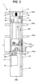
FIG. 2] FIG. 2 illustrates a method for extending a main rope of the construction elevator according to the first embodiment, and illustrates a state in which a second machine room is being moved. - [
FIG. 3] FIG. 3 illustrates a method for extending the main rope of the construction elevator according to the first embodiment, and illustrates a state in which a first machine room is being moved. - [
FIG. 4] FIG. 4 illustrates a method for extending the main rope of the construction elevator according to the first embodiment, and illustrates a state after a machine room unit is moved. - [
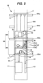
FIG. 5] FIG. 5 is a schematic configuration diagram illustrating a construction elevator according to a second embodiment. - [
FIG. 6] FIG. 6 illustrates a method for extending the main rope of the construction elevator according to the second embodiment, and illustrates a state in which a second machine room is being moved. - [
FIG. 7] FIG. 7 illustrates a method for extending the main rope of the construction elevator according to the second embodiment, and illustrates a state in which a first machine room is being moved. - [
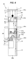
FIG. 8] FIG. 8 is a schematic configuration diagram illustrating a construction elevator according to a third embodiment. - [
FIG. 9] FIG. 9 illustrates a method for extending the main rope of the construction elevator according to the third embodiment, and illustrates a state in which a pulley is being moved. - [
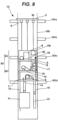
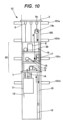
FIG. 10] FIG. 10 illustrates a method for extending the main rope of the construction elevator according to the third embodiment, and illustrates a state in which a machine room unit is being moved. - [
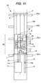
FIG. 11] FIG. 11 is a schematic configuration diagram illustrating a construction elevator according to a fourth embodiment. - [
FIG. 12] FIG. 12 is a schematic configuration diagram illustrating a construction elevator according to a fifth embodiment. - Hereinafter, a construction elevator and a method for extending a main rope according to embodiments will be described with reference to
FIGS. 1 to 12 . Note that in the drawings, common members are denoted by the same reference signs. - First, the configuration of a construction elevator according to a first embodiment (hereinafter referred to as the "present example") will be described with reference to
FIG. 1 . -
FIG. 1 is a schematic configuration diagram illustrating the construction elevator according to the present example. - The elevator illustrated in
FIG. 1 is a construction elevator that is provided in a building structure under construction and used for transporting materials and people. As shown inFIG. 1 , aconstruction elevator 1 is equipped with asupport member 2 disposed at the top of ahoistway 100 of the building structure, a machine room unit 3, and alifting device 6 for lifting the machine room unit 3. Theconstruction elevator 1 is also equipped with a hoistingmachine 9, amain rope 10, acar 11 on which people and materials are loaded, and acounterweight 12. Thecar 11 and thecounterweight 12 illustrate examples of elevating bodies. Note that the positional relationship between thecar 11 and thecounterweight 12 may be reversed. That is, inFIG. 1 , the counterweight may correspond toreference sign 11, and the car may correspond toreference sign 12. Hereinafter, the direction in which thecar 11 and thecounterweight 12 serving as elevating bodies move vertically is defined as the vertical direction. - A car-
side pulley 11a is provided at the top of thecar 11. In addition, a weight-side pulley 12a is provided at the top of thecounterweight 12. Themain rope 10 is wrapped around the car-side pulley 11a and the weight-side pulley 12a. Themain rope 10 is also wrapped around the sheave of the hoistingmachine 9 installed in the machine room unit 3 to be described later. - The
main rope 10 is wound around arope reel 15 provided in the machine room unit 3 to be described later, and is drawn from therope reel 15. Furthermore, the end of themain rope 10 on the opposite side from therope reel 15 is fixed to a rope-fixing portion 14 in the machine room unit 3. Furthermore, themain rope 10 is wrapped from therope reel 15, through apulley 19 to be described later, to the weight-side pulley 12a, the hoistingmachine 9, and the car-side pulley 11a in this order, and the end of themain rope 10 is fixed to the rope-fixingportion 14. Then, when the hoistingmachine 9 is driven, thecar 11 and thecounterweight 12 move vertically in thehoistway 100. - The
support member 2 is installed on abeam 101a provided at the uppermost portion of the hoistway 100 or a recess provided in the wall surface of thehoistway 100. Thelifting device 6 is provided to thesupport member 2. The machine room unit 3 is disposed belowsupport member 2 in the vertical direction. Furthermore, the machine room unit 3 is suspended from thesupport member 2 with thelifting device 6 therebetween. The machine room unit 3 is supported by thelifting device 6 so as to be liftable (movable). Note that thelifting device 6 may be provided in afirst machine room 4 and asecond machine room 5 of the machine room unit 3 to be described later, and the lifting rope of thelifting device 6 may be provided in thesupport member 2. - The machine room unit 3 has the
first machine room 4 and thesecond machine room 5. Thefirst machine room 4 is disposed below thesecond machine room 5 in the vertical direction. Thefirst machine room 4 and thesecond machine room 5 are separably coupled, and are each independently lifted by thelifting device 6. - A
movable support mechanism 7 is provided at the bottom of thefirst machine room 4 in the vertical direction. Themovable support mechanism 7 is configured so as to be stretchable from thefirst machine room 4 toward the wall surface of thehoistway 100. Furthermore, themovable support mechanism 7 is placed onbeams hoistway 100 or a recess provided in the wall surface of thehoistway 100. Themovable support mechanism 7 supports the machine room unit 3 or thefirst machine room 4 at a predetermined position in thehoistway 100. Note that themovable support mechanism 7 is not limited to the above-described one, and various other fixing mechanisms, such as an engaging member that engages with a guide rail for supporting thecar 11 in a vertically movable manner or the wall surface of thehoistway 100, and a fastening member that is fastened to the wall surface, may be applied. - The
first machine room 4 has anupper machine room 4a and alower machine room 4b. Theupper machine room 4a is installed at the top of thelower machine room 4b in the vertical direction. Furthermore, thesecond machine room 5 is installed at the top of theupper machine room 4a in the vertical direction. The hoistingmachine 9 is installed in thelower machine room 4b. Furthermore, the rope-fixingportion 14 for fixing the end of themain rope 10 is installed in thelower machine room 4b. - Note that in the present example, the configuration in which the
first machine room 4 is divided into two, theupper machine room 4a and thelower machine room 4b has been described. However, thefirst machine room 4 may be a single machine room or may be divided into three or more machine rooms. Also note that in the present example, thesecond machine room 5 is described as a single machine room, but may be divided into two or more machine rooms similarly to thefirst machine room 4. - In the
upper machine room 4a, therope reel 15 around which themain rope 10 is wound, afirst rope gripper 16, asecond rope gripper 17, and adeflector 22 are installed. Themain rope 10 for extension is wound around therope reel 15. Then, when raising the machine room unit 3, themain rope 10 for extension is drawn from therope reel 15. Note that in the present example, therope reel 15 is installed in the machine room unit 3, but the present invention is not limited thereto, and therope reel 15 may be installed in apit 100b, which is the bottom of thehoistway 100, or outside thehoistway 100. - The
deflector 22 is disposed near therope reel 15. Thedeflector 22 changes the direction of themain rope 10 drawn from therope reel 15 to the direction toward thesecond machine room 5. - The
first rope gripper 16 is provided near thedeflector 22 and therope reel 15. Thefirst rope gripper 16 releasably grips themain rope 10, the direction of which has been changed by thedeflector 22. In addition, thefirst rope gripper 16 grips themain rope 10 on the rope reel side (hereinafter, simply referred to as the "first side") A of thepulley 19 to be described later in themain rope 10. Furthermore, thefirst rope gripper 16 grips themain rope 10, thereby restricting the movement of themain rope 10. Note that thefirst rope gripper 16 may be provided to therope reel 15 or thedeflector 22. - The
second rope gripper 17 is disposed on themain rope 10 on the elevating body side, that is, thecounterweight 12 andcar 11 side (hereinafter, simply referred to as the "second side") B, of thepulley 19 to be described later. Thesecond rope gripper 17 has agrip portion 17a and arope drum 17b. Similarly to thefirst rope gripper 16, thegrip portion 17a releasably grips themain rope 10. Furthermore, thegrip portion 17a grips themain rope 10, thereby restricting the movement of themain rope 10. - The
rope drum 17b is disposed above thegrip portion 17a in the vertical direction. Furthermore, therope drum 17b is disposed closer to thepulley 19 than thegrip portion 17a. Therefore, thegrip portion 17a is disposed closer to the elevating body side than therope drum 17b, that is, closer to thecounterweight 12 andcar 11 side. Therope drum 17b is supported in such a manner that the rotation thereof can be locked and released. Therope drum 17b is wrapped with N or more turns (N is 1 or more) of themain rope 10. When the rotation of therope drum 17b is locked, frictional force is generated between therope drum 17b and themain rope 10. - As described above, the
first machine room 4 has the two-story structure of theupper machine room 4a and thelower machine room 4b, so that the horizontal space in thehoistway 100 can be reduced. Note that thefirst machine room 4 is not limited to the two-story structure of theupper machine room 4a and thelower machine room 4b, but may have a single-story structure in which the hoistingmachine 9, the rope-fixingportion 14, therope reel 15, thefirst rope gripper 16, and thesecond rope gripper 17 are installed in a single machine room. - Next, the
second machine room 5 will be described. - The
second machine room 5 is separably coupled to the top of theupper machine room 4a in thefirst machine room 4. In thesecond machine room 5, acontrol panel 8 that controls the hoistingmachine 9, thecar 11, and the like, thepulley 19, and athird rope gripper 18 are installed. - The
control panel 8 and thecar 11 are electrically connected through atail cord 13. In addition, atail cord reel 20 is installed near thecontrol panel 8. Thetail cord 13 for extension is wound around thetail cord reel 20. Then, when raising thesecond machine room 5, thetail cord 13 is drawn from thetail cord reel 20. - The
pulley 19 is rotatably supported in thesecond machine room 5. Thepulley 19 is disposed between therope reel 15, and thecar 11 andcounterweight 12 that represent the elevating bodies. Themain rope 10 drawn from therope reel 15 is wrapped around thepulley 19. Furthermore, thepulley 19 changes the direction in which themain rope 10 extends from up to down. - The
third rope gripper 18 is disposed near thepulley 19. Thethird rope gripper 18 is disposed on themain rope 10 on the second side B of thepulley 19. In addition, thethird rope gripper 18 is disposed closer to thepulley 19 than therope drum 17b of thesecond rope gripper 17. Similarly to thefirst rope gripper 16, thethird rope gripper 18 releasably grips themain rope 10. - In the drawings, in the
first rope gripper 16, thegrip portion 17a of thesecond rope gripper 17, and thethird rope gripper 18, the state in which themain rope 10 is gripped is illustrated in black, and the state in which themain rope 10 is released is illustrated in white. - As illustrated in
FIG. 1 , during the operation of theconstruction elevator 1, thethird rope gripper 18 operates to grip themain rope 10, and thefirst rope gripper 16 and thegrip portion 17a of thesecond rope gripper 17 are released. Therefore, one end of themain rope 10 is fixed to the rope-fixingportion 14, and the other end of themain rope 10 is fixed to thethird rope gripper 18. - In addition, the
rope drum 17b of thesecond rope gripper 17 is non-rotatably fixed. As described above, since themain rope 10 is wrapped around therope drum 17b, frictional force is generated between therope drum 17b and themain rope 10. The frictional force generated between therope drum 17b and themain rope 10 can reduce the load applied to thethird rope gripper 18. As a result, the force (gripping force) with which thethird rope gripper 18 grips themain rope 10 can be reduced, and damage to themain rope 10 due to the gripping of thethird rope gripper 18 can be suppressed. As the number of windings of themain rope 10 around therope drum 17b increases, the gripping force of thethird rope gripper 18 can be reduced. - Note that in the present example, the
third rope gripper 18 grips themain rope 10 to fix the other end of themain rope 10, but the present invention is not limited thereto. For example, thethird rope gripper 18 may be released, themain rope 10 may be gripped by thefirst rope gripper 16, and the other end of themain rope 10 may be fixed by thefirst rope gripper 16. At least it is sufficient if the other end of themain rope 10 is fixed by gripping themain rope 10 between therope drum 17b of thesecond rope gripper 17 and therope reel 15. Therefore, the other end of themain rope 10 may be fixed at therope reel 15. - Next, a method for extending the
main rope 10 of theconstruction elevator 1 having the above-described configuration, that is, a method for extending the operation floor by raising the machine room unit 3 will be described with reference toFIGS. 2 to 4 . -
FIGS. 2 to 4 are explanatory diagrams illustrating a method for extending themain rope 10. - As illustrated in
FIG. 2 , when extending themain rope 10, first, thecar 11 and thefirst machine room 4 are coupled by achain 201, and thecar 11 is fixed. In addition, thecounterweight 12 is lowered to thepit 100b, and thecounterweight 12 is placed on a buffer (not illustrated) installed in thepit 100b. Thus, tension from thecar 11 and thecounterweight 12 is not applied to themain rope 10. - Next, the
main rope 10 is gripped by thegrip portion 17a of thesecond rope gripper 17, and the gripping of themain rope 10 by thethird rope gripper 18 is released. Note that if thefirst rope gripper 16 is gripping themain rope 10, the gripping of themain rope 10 by thefirst rope gripper 16 is released. Then thefirst machine room 4 and thesecond machine room 5 are divided. - Next, the
lifting device 6 coupled to thesecond machine room 5 is operated to raise only thesecond machine room 5 to a predetermined height (thebeam 101b in the example illustrated inFIG. 2 ). Note that since themain rope 10 is folded back by thepulley 19, the length (height) for raising thesecond machine room 5 only needs to be about half the length of the extension of themain rope 10. As thesecond machine room 5 rises, thepulley 19 provided in thesecond machine room 5 also rises. When thesecond machine room 5 is raised to the predetermined height, thelifting device 6 is stopped, and thesecond machine room 5 and thepulley 19 are temporarily fixed using thelifting device 6, a second machine room support mechanism (not illustrated), or the like. - Here, one end of the
main rope 10 is fixed by thegrip portion 17a of thesecond rope gripper 17, but the other end of themain rope 10, that is, therope reel 15 side, is not fixed. Therefore, as thesecond machine room 5 and thepulley 19 rise, themain rope 10 on therope reel 15 side is pulled, and themain rope 10 for extension is drawn from therope reel 15. Thus, the raising operation of thesecond machine room 5 and thepulley 19 and the operation of drawing out themain rope 10 from therope reel 15 can be performed simultaneously. - When moving the
second machine room 5, the other end of themain rope 10 is fixed by thegrip portion 17a of thesecond rope gripper 17 provided in thefirst machine room 4. Therefore, themain rope 10 is not drawn vertically downward from thefirst machine room 4. Thus, even during the movement of thesecond machine room 5, the hoistingmachine 9 can be driven to use thecar 11. - Next, as shown in
FIG. 3 , themain rope 10 is gripped by thefirst rope gripper 16, and the gripping of themain rope 10 by thegrip portion 17a of thesecond rope gripper 17 is released. In addition, the fixing of therope drum 17b of thesecond rope gripper 17 is released, thereby allowing therope drum 17b to rotate. Therefore, one end of themain rope 10 is fixed to the rope-fixingportion 14, and the other end of themain rope 10 is fixed to thefirst rope gripper 16. - Next, the
movable support mechanism 7 is retracted to release the support of thefirst machine room 4 by themovable support mechanism 7. Then the liftingdevice 6 coupled to thefirst machine room 4 is operated to raise thefirst machine room 4 to a predetermined height (thebeam 101c in the example illustrated inFIGS. 3 and4 ). Thus, themain rope 10 for extension drawn from therope reel 15 in the operation illustrated inFIG. 2 is sent out toward thecounterweight 12 andcar 11 side through thepulley 19 and thesecond rope gripper 17. - When the
first machine room 4 rises to the predetermined height, thelifting device 6 is stopped. Then, as illustrated inFIG. 4 , themovable support mechanism 7 is extended to place themovable support mechanism 7 on thebeam 101c. In addition, thefirst machine room 4 and thesecond machine room 5 are coupled. Thus, the machine room unit 3, which is composed of thefirst machine room 4 and thesecond machine room 5, can be raised to the predetermined height. - Next, the rotation of the
rope drum 17b of thesecond rope gripper 17 is locked, and themain rope 10 is gripped by thethird rope gripper 18. When locking the rotation of therope drum 17b, it is preferable to adjust the phase of therope drum 17b. Therefore, before locking the rotation of therope drum 17b, themain rope 10 is first gripped by thegrip portion 17a of thesecond rope gripper 17. Thus, the weight of themain rope 10 is not applied to therope drum 17b of thesecond rope gripper 17, so that therope drum 17b can be easily rotated, and the work of adjusting the phase of therope drum 17b can be easily performed. Then, when the work of adjusting the phase of therope drum 17b is completed, the rotation of therope drum 17b is locked. - In addition, when the work of locking the rotation of the
rope drum 17b is completed, themain rope 10 is gripped by thethird rope gripper 18. Thereafter, the gripping of themain rope 10 by thegrip portion 17a of thesecond rope gripper 17 is released. As described above, themain rope 10 is once gripped by thegrip portion 17a of thesecond rope gripper 17, whereby it is possible to prevent thecounterweight 12 from falling or themain rope 10 from falling under its own weight. - Next, the gripping of the
main rope 10 by thefirst rope gripper 16 is released. Then the coupling between thecar 11 and thefirst machine room 4 is released, and thecounterweight 12 is pulled up from the buffer (not illustrated). By performing such steps, the work of extending themain rope 10 and the work of expanding the operation floor of theconstruction elevator 1 are completed. - With the
construction elevator 1 and the method for extending themain rope 10 according to the present example, themain rope 10 can be extended without sliding themain rope 10 on therope grippers grip portion 17a. Thus, wear of themain rope 10 can be prevented, and the gripping force of therope grippers grip portion 17a can be easily adjusted. - In addition, the machine room unit 3 is divided into the
first machine room 4 and thesecond machine room 5, each of which is independently lifted. Thus, the weight applied to thelifting device 6 can be reduced, and thelifting device 6 can be prevented from increasing in size. - Hereinafter, a construction elevator according to a second embodiment will be described with reference to
FIGS. 5 to 7 . -
FIG. 5 is a schematic configuration diagram illustrating the construction elevator according to the second embodiment, andFIGS. 6 and7 illustrate a method for extending the main rope of the construction elevator according to the second embodiment. - The construction elevator according to the second embodiment is different from the
construction elevator 1 according to the first embodiment in the configuration of the machine room unit. Therefore, here, the same reference signs are given to portions common to theconstruction elevator 1 according to the first embodiment, and redundant description will be omitted. - As illustrated in
FIG. 5 , aconstruction elevator 1B has amachine room unit 3B composed of afirst machine room 4B and asecond machine room 5B. In thefirst machine room 4B, the hoistingmachine 9, the rope-fixingportion 14 for fixing the end of themain rope 10, therope reel 15, thefirst rope gripper 16, and asecond rope gripper 27 are installed. In thesecond machine room 5B, thecontrol panel 8, thetail cord reel 20, and thepulley 19 are installed. - Since the configurations of the
control panel 8, the hoistingmachine 9, the rope-fixingportion 14, therope reel 15, thefirst rope gripper 16, thepulley 19, and thetail cord reel 20 are similar to those of theconstruction elevator 1 according to the first embodiment, the description thereof will be omitted. A detailed configuration of thesecond rope gripper 27 will be described later. - The
second machine room 5B is disposed above thefirst machine room 4B in the vertical direction. Furthermore, similarly to thefirst machine room 4B, amovable support mechanism 21 is provided in thesecond machine room 5B. Themovable support mechanism 21 is configured so as to be stretchable from thesecond machine room 5B toward the wall surface of thehoistway 100. Furthermore, themovable support mechanism 21 is placed on thebeams hoistway 100 or a recess provided in the wall surface of thehoistway 100. Themovable support mechanism 21 supports the machine room unit 3 or thesecond machine room 5B at a predetermined position in thehoistway 100. - The
third rope gripper 18 is not provided in thesecond machine room 5B according to the second embodiment. - The
second rope gripper 27 has alower grip portion 27a, arope drum 27b, and anupper grip portion 27c. Since the configurations of thelower grip portion 27a and therope drum 27b are similar to those of thegrip portion 17a and therope drum 17b of thesecond rope gripper 17 according to the first embodiment, the description thereof will be omitted. - The
upper grip portion 27c is disposed above therope drum 27b in the vertical direction. That is, theupper grip portion 27c is disposed closer to thepulley 19 than therope drum 27b. Similarly to thefirst rope gripper 16 and thelower grip portion 27a, theupper grip portion 27c releasably grips themain rope 10. Theupper grip portion 27c has similar operation and effect to thethird rope gripper 18 according to the first embodiment. - As illustrated in
FIG. 5 , during the operation of theconstruction elevator 1B, theupper grip portion 27c of thesecond rope gripper 27 operates to grip themain rope 10, and thefirst rope gripper 16 and thelower grip portion 27a of thesecond rope gripper 27 are released. Therefore, one end of themain rope 10 is fixed to the rope-fixingportion 14, and the other end of themain rope 10 is fixed to theupper grip portion 27c of thesecond rope gripper 27. - In addition, since the
rope drum 27b of thesecond rope gripper 27 is non-rotatably fixed, the load applied to theupper grip portion 27c can be reduced. - Note that also in the
construction elevator 1B according to the second embodiment, theupper grip portion 27c of thesecond rope gripper 27 may be released, themain rope 10 may be gripped by thefirst rope gripper 16, and the other end of themain rope 10 may be fixed by thefirst rope gripper 16. - Next, a method of extending the
main rope 10 of theconstruction elevator 1B according to the second embodiment will be described with reference toFIGS. 6 and7 . - First, as illustrated in
FIG. 6 , thecar 11 and thefirst machine room 4 are coupled by thechain 201, and thecar 11 is fixed. In addition, thecounterweight 12 is lowered to thepit 100b, and thecounterweight 12 is placed on a buffer (not illustrated) installed in thepit 100b. - Next, while the
main rope 10 is gripped by theupper grip portion 27c of thesecond rope gripper 27, themovable support mechanism 21 is retracted to release the support of thesecond machine room 5B by themovable support mechanism 21. Thelifting device 6 coupled to thesecond machine room 5B is operated to raise only thesecond machine room 5B to a predetermined height (thebeam 101b in the example illustrated inFIG. 2 ) . As thesecond machine room 5B rises, thepulley 19 provided in thesecond machine room 5B also rises. - As illustrated in
FIG. 7 , when thesecond machine room 5B is raised to the predetermined height, thelifting device 6 is stopped, and themovable support mechanism 21 is extended to place themovable support mechanism 21 on thebeam 101b. In addition, as thesecond machine room 5B and thepulley 19 rise, themain rope 10 on therope reel 15 side is pulled, and themain rope 10 for extension is drawn from therope reel 15. Thus, the raising operation of thesecond machine room 5B and thepulley 19 and the operation of drawing out themain rope 10 from therope reel 15 can be performed simultaneously. - As illustrated in
FIG. 6 , when moving thesecond machine room 5B, the other end of themain rope 10 is fixed by theupper grip portion 27c of thesecond rope gripper 27 provided in thefirst machine room 4B. Therefore,themain rope 10 is not drawn vertically downward from thefirst machine room 4B. Thus, even during the movement of thesecond machine room 5B, the hoistingmachine 9 can be driven to use thecar 11. That is, theconstruction elevator 1B can be moved even during the work of extending themain rope 10, thereby allowing an improvement in the work of installing theconstruction elevator 1B and building structure construction work. - Note that when moving the
second machine room 5B, the other end of themain rope 10 may be fixed by thelower grip portion 27a of thesecond rope gripper 27 provided in thefirst machine room 4B. Also in this case, themain rope 10 is not drawn vertically downward from thefirst machine room 4B. - Next, as illustrated in
FIG. 7 , themain rope 10 is gripped by thefirst rope gripper 16, and the gripping of themain rope 10 by theupper grip portion 27c of thesecond rope gripper 27 is released. In addition, the fixing of therope drum 27b of thesecond rope gripper 27 is released, thereby allowing, therope drum 27b to rotate. Therefore, one end of themain rope 10 is fixed to the rope-fixingportion 14, and the other end of themain rope 10 is fixed to thefirst rope gripper 16. - Next, the
movable support mechanism 7 is retracted to release the support of thefirst machine room 4B by themovable support mechanism 7. Then the liftingdevice 6 coupled to thefirst machine room 4B is operated to raise thefirst machine room 4B to a predetermined height (thebeam 101c in the example illustrated inFIG. 7 ). Then, when thefirst machine room 4B is raised to the predetermined height, thelifting device 6 is stopped, and themovable support mechanism 7 is extended to place themovable support mechanism 7 on thebeam 101c. Thus, thefirst machine room 4B and thesecond machine room 5B can be raised to the predetermined height. - Next, the rotation of the
rope drum 27b of thesecond rope gripper 27 is locked, and themain rope 10 is gripped by theupper grip portion 27c. Here, before locking the rotation of therope drum 27b, themain rope 10 is first gripped by thelower grip portion 27a of thesecond rope gripper 27. Then the phase of therope drum 27b is adjusted, and the rotation of therope drum 27b is locked. When the work of locking the rotation of therope drum 27b is completed, themain rope 10 is gripped by theupper grip portion 27c. Thereafter, the gripping of themain rope 10 by thelower grip portion 27a is released. - Next, the gripping of the
main rope 10 by thefirst rope gripper 16 is released. Then the coupling between thecar 11 and thefirst machine room 4B is released, and thecounterweight 12 is pulled up from the buffer (not illustrated). Thus, the work of extending themain rope 10 and the work of expanding the operation floor of theconstruction elevator 1B are completed. - The other configurations are similar to those of the
construction elevator 1 according to the first embodiment, and thus the description thereof will be omitted. Theconstruction elevator 1B according to the second embodiment can also provide similar operational effects to those of theconstruction elevator 1 according to the first embodiment described above. - Hereinafter, a construction elevator according to a third embodiment will be described with reference to
FIGS. 8 to 10 . -
FIG. 8 is a schematic configuration diagram illustrating the construction elevator according to the third embodiment, andFIGS. 9 and10 illustrate a method for extending the main rope of the construction elevator according to the third embodiment. - The construction elevator according to the third embodiment is different from the
construction elevator 1 according to the first embodiment in the configuration of the machine room unit. Therefore, here, the same reference signs are given to portions common to theconstruction elevator 1 according to the first embodiment, and redundant description will be omitted. - As illustrated in
FIG. 8 , aconstruction elevator 1C has amachine room unit 3C composed of afirst machine room 4C and asecond machine room 5C, and a pulley 19C. Thefirst machine room 4C and thesecond machine room 5C are integrally formed. In thefirst machine room 4C, the hoistingmachine 9, the rope-fixingportion 14 for fixing the end of themain rope 10, therope reel 15, thefirst rope gripper 16, and thesecond rope gripper 17 are installed. In thesecond machine room 5B, thecontrol panel 8, thetail cord reel 20, and thethird rope gripper 18 are installed. - Since the configurations of the
control panel 8, the hoistingmachine 9, the rope-fixingportion 14, therope reel 15, thefirst rope gripper 16, thesecond rope gripper 17, thethird rope gripper 18, and thetail cord reel 20 are similar to those of theconstruction elevator 1 according to the first embodiment, the description thereof will be omitted. - The pulley 19C is supported by a pulley lifting device 6C so as to be liftable (movable) along the vertical direction. That is, the pulley 19C is moved independently from the
machine room unit 3C by the pulley lifting device 6C. In addition, the pulley 19C is rotatably supported, and themain rope 10 is wrapped therearound. Thefirst rope gripper 16 is disposed on themain rope 10 on therope reel 15 side, that is, the first side A, of the pulley 19C. Furthermore, thesecond rope gripper 17 and thethird rope gripper 18 are arranged on the main rope on thecounterweight 12 andcar 11 side, that is, the second side B, of the pulley 19C. - As illustrated in
FIG. 9 , during the operation of theconstruction elevator 1C, thethird rope gripper 18 operates to grip themain rope 10, and thefirst rope gripper 16 and thegrip portion 17a of thesecond rope gripper 17 are released. Therefore, one end of themain rope 10 is fixed to the rope-fixingportion 14, and the other end of themain rope 10 is fixed to thethird rope gripper 18. In addition, since therope drum 17b of thesecond rope gripper 17 is non-rotatably fixed, the load applied to thethird rope gripper 18 can be reduced. - Note that also in the
construction elevator 1C according to the third embodiment, thethird rope gripper 18 may be released, themain rope 10 may be gripped by thefirst rope gripper 16, and the other end of themain rope 10 may be fixed by thefirst rope gripper 16. - Next, a method of extending the
main rope 10 of theconstruction elevator 1C according to the third embodiment will be described with reference toFIGS. 9 and10 . - First, as illustrated in
FIG. 9 , thecar 11 and themachine room unit 3C are coupled by thechain 201, and thecar 11 is fixed. In addition, thecounterweight 12 is lowered to thepit 100b, and thecounterweight 12 is placed on a buffer (not illustrated) installed in thepit 100b. - Next, the pulley lifting device 6C coupled to the pulley 19C is driven to raise only the pulley 19C to a predetermined height. At this time, the
main rope 10 on the second side B of the pulley 19C is fixed by thethird rope gripper 18. Therefore, themain rope 10 can be drawn from therope reel 15 by raising the pulley 19C. In addition, since themain rope 10 is folded back by the pulley 19C, the length (height) for raising the pulley 19C only needs to be about half the length of the extension of themain rope 10. - Note that although the example in which the
main rope 10 is gripped by thethird rope gripper 18 has been described, the present invention is not limited to this. Thethird rope gripper 18 may be released, and themain rope 10 may be fixed by thegrip portion 17a of thesecond rope gripper 17. When the pulley 19C is raised to the predetermined height, thelifting device 6 is stopped and the pulley 19C is temporarily fixed in thehoistway 100. - In the example illustrated in
FIG. 9 , thecar 11 and themachine room unit 3C are coupled and thecounterweight 12 is placed on the buffer, but the present invention is not limited thereto. Here, one end of themain rope 10 on the second side B during the raising operation of the pulley 19C is fixed to the rope-fixingportion 14, and the other end thereof on the second side B is fixed to thethird rope gripper 18. Therefore, even during the movement of the pulley 19C, it is not necessary to couple thecar 11 to themachine room unit 3C and place thecounterweight 12 on the buffer. Furthermore, even during the movement of the pulley 19C, the hoistingmachine 9 may be driven to use thecar 11. - Next, when raising the
machine room unit 3C, as illustrated inFIG. 10 , themain rope 10 is gripped by thefirst rope gripper 16, and the gripping of themain rope 10 by thethird rope gripper 18 is released. In addition, the fixing of therope drum 17b of thesecond rope gripper 17 is released, thereby allowing therope drum 17b to rotate. Therefore, one end of themain rope 10 is fixed to the rope-fixingportion 14, and the other end of themain rope 10 is fixed to thefirst rope gripper 16. - Here, in a case where the
car 11 is not coupled to themachine room unit 3C and thecounterweight 12 is not placed on the buffer, thecar 11 and themachine room unit 3C are coupled and thecounterweight 12 is placed on the buffer before the above-described work (step). - Next, the
movable support mechanism 7 is retracted to release the support of themachine room unit 3C by themovable support mechanism 7. Then the liftingdevice 6 coupled to themachine room unit 3C is operated to raise themachine room unit 3C to a predetermined height. Then, when themachine room unit 3C is raised to the predetermined height, thelifting device 6 is stopped, and themovable support mechanism 7 is extended to place themovable support mechanism 7 on thebeam 101c. Thus, themachine room unit 3C can be raised to the predetermined height. - Next, the rotation of the
rope drum 17b of thesecond rope gripper 17 is locked, and themain rope 10 is gripped by thethird rope gripper 18. Here, before locking the rotation of therope drum 17b, themain rope 10 is first gripped by thegrip portion 17a of thesecond rope gripper 17. Then the phase of therope drum 17b is adjusted, and the rotation of therope drum 17b is locked. When the work of locking the rotation of therope drum 17b is completed, themain rope 10 is gripped by thethird rope gripper 18. Thereafter, the gripping of themain rope 10 by thegrip portion 17a of thesecond rope gripper 17 is released. - Next, the gripping of the
main rope 10 by thefirst rope gripper 16 is released. Then the coupling between thecar 11 and themachine room unit 3C is released, and thecounterweight 12 is pulled up from the buffer (not illustrated). Thus, the work of extending themain rope 10 and the work of expanding the operation floor of theconstruction elevator 1C are completed. - The other configurations are similar to those of the
construction elevator 1 according to the first embodiment, and thus the description thereof will be omitted. Theconstruction elevator 1C according to the third embodiment can also provide similar operational effects to those of theconstruction elevator 1 according to the first embodiment described above. - In addition, in the
construction elevator 1 according to the first embodiment and theconstruction elevator 1B according to the second embodiment, thepulley 19 rises together with thesecond machine room main rope 10 is drawn from therope reel 15. That is, in theconstruction elevator 1 according to the first embodiment and theconstruction elevator 1B according to the second embodiment, thelifting device 6 for lifting themachine room unit 3, 3B serves as a pulley lifting device. Meanwhile, in theconstruction elevator 1C according to the third embodiment, only the pulley 19C rises independently of themachine room unit 3C, so that themain rope 10 is drawn from therope reel 15. - Next, a construction elevator according to a fourth embodiment will be described with reference to
FIG. 11 . -
FIG. 11 is a schematic configuration diagram illustrating the construction elevator according to the fourth embodiment. - The construction elevator according to the fourth embodiment is different from the construction elevators according to the first and third embodiments in the order in which the main rope is looped over the car and the counterweight. Therefore, here, the same reference signs are given to portions common to the
construction elevators - As illustrated in
FIG. 11 , aconstruction elevator 1D has amachine room unit 3D, thecar 11, and thecounterweight 12. Therope reel 15 around which themain rope 10 is wound, the hoistingmachine 9, and the like are arranged in themachine room unit 3D. - In the
construction elevator 1D according to the fourth embodiment, themain rope 10 is wrapped from therope reel 15, through thepulley 19, to the car-side pulley 11a provided on thecar 11, the hoistingmachine 9, and the weight-side pulley 12a provided on thecounterweight 12, in this order. Furthermore, one end of themain rope 10 extending from the weight-side pulley 12a is fixed to the rope-fixingportion 14 of themachine room unit 3D. - The other configurations are similar to those of the
construction elevators construction elevator 1D according to the fourth embodiment can also provide similar operational effects to those of theconstruction elevators - Next, a construction elevator according to a fifth embodiment will be described with reference to
FIG. 12 . -
FIG. 12 is a schematic configuration diagram illustrating the construction elevator according to the fifth embodiment. - The construction elevator according to the fifth embodiment is different from the construction elevator according to the second embodiment in the order in which the main rope is looped over the car and the counterweight. Therefore, here, the same reference signs are given to portions common to the
construction elevator 1B according to the second embodiment, and redundant description will be omitted. - As illustrated in
FIG. 12 , aconstruction elevator 1E has amachine room unit 3E, thecar 11, and thecounterweight 12. Therope reel 15 around which themain rope 10 is wound, the hoistingmachine 9, and the like are arranged in themachine room unit 3E. - In the
construction elevator 1E according to the fifth embodiment, themain rope 10 is wound from therope reel 15, through thepulley 19, to the car-side pulley 11a provided on thecar 11, the hoistingmachine 9, and the weight-side pulley 12a provided on thecounterweight 12, in this order. Furthermore, .one end of themain rope 10 extending from the weight-side pulley 12a is fixed to the rope-fixingportion 14 of themachine room unit 3E. - . The other configurations are similar to those of the
construction elevator 1B according to the second embodiment, and thus the description thereof will be omitted. Theconstruction elevator 1E according to the fifth embodiment can also provide similar operational effects to as theconstruction elevator 1B according to the second embodiment described above. - Note that the present invention is not limited to the embodiments described above and illustrated in the drawings, and various modifications can be made without departing from the gist of the invention described in the claims.
- Note that in the present specification, words such as "parallel" and "orthogonal" are used, but these do not mean only strictly "parallel" and "orthogonal", and may include "parallel" and "orthogonal" and even be in a state of "substantially parallel" or "substantially orthogonal" within the range in which the functions can be exhibited.
-
- 1, 1B, 1C, 1D, 1E construction elevator
- 2 support member
- 3, 3B, 3C, 3D, 3E machine room unit
- 4, 4B, 4C first machine room
- 4a upper machine room
- 4b lower machine room
- 5, 5B, 5C second machine room
- 6 lifting device
- 6C pulley lifting device
- 7, 21 movable support mechanism
- 8 control panel
- 9 hoisting machine
- 10 main rope
- 11 car (elevating body)
- 11a car-side pulley
- 12 counterweight (elevating body)
- 12a weight-side pulley
- 13 tail cord
- 14 rope-fixing portion
- 15 rope reel
- 16 first rope gripper
- 17, 27 second rope gripper
- 17a grip portion
- 17b rope drum
- 18 third rope gripper
- 19, 19C pulley
- 20 tail cord reel
- 27a lower grip portion
- 27b rope drum
- 27c upper grip portion
- 100 hoistway
- 100b pit
- 101a, 101b, 101c, 101d beam
Claims (10)
- A construction elevator comprising:a rope reel around which a main rope is wound;an elevating body around which the main rope drawn from the rope reel is wrapped and that moves vertically in a hoistway of a building structure;a pulley that is disposed on the main rope between the rope reel and the elevating body and around which the main rope drawn from the rope reel is wrapped;a first rope gripper that releasably grips the main rope on a rope reel side of the pulley; anda second rope gripper that releasably grips the main rope on an elevating body side of the pulley, wherein the pulley is supported so as to be movable along a direction in which the elevating body moves vertically.
- The construction elevator according to claim 1, wherein the second rope gripper hasa grip portion that releasably grips the main rope, anda rope drum around which the main rope is wrapped at least once, the rope drum being supported in such a manner that rotation can be locked and released.
- The construction elevator according to claim 2, further comprising a third rope gripper that releasably grips the main rope on the elevating body side of the pulley, wherein the third rope gripper is disposed closer to the pulley than the rope drum of the second rope gripper.
- The construction elevator according to claim 2, wherein the grip portion hasan upper grip portion disposed closer to the pulley than the rope drum, anda lower grip portion disposed closer to the elevating body than the rope drum.
- The construction elevator according to claim 1, further comprising:a machine room unit in which a rope-fixing portion for fixing an end of the main rope is provided; anda lifting device that supports the machine room unit in a liftable manner.
- The construction elevator according to claim 5, wherein the machine room unit has:a first machine room in which the rope-fixing portion is provided; anda second machine room that is disposed above the first machine room in a vertical direction and in which the pulley is disposed.
- The construction elevator according to claim 6, wherein the first machine room and the second machine room are separably coupled.
- The construction elevator according to claim 7, wherein the pulley is rotatably supported in the second machine chamber, and is supported so as to be liftable together with the second machine chamber by the lifting device.
- The construction elevator according to any one of claims 6 to 8, wherein the second rope gripper is disposed in the first machine room.
- A method for extending a main rope of a construction elevator equipped with: a rope reel around which the main rope is wound; an elevating body around which the main rope drawn from the rope reel is wrapped and that moves vertically in a hoistway of a building structure; a pulley that is disposed on the main rope between the rope reel and the elevating body and around which the main rope drawn from the rope reel is wrapped; a first rope gripper that releasably grips the main rope on a rope reel side of the pulley; and a second rope gripper that releasably grips the main rope on an elevating body side of the pulley, the method comprising the steps of:gripping the main rope with the second rope gripper;releasing the gripping of the main rope by the first rope gripper, raising the pulley to a predetermined height along a direction in which the elevating body moves vertically, and drawing the main rope from the rope reel;after raising the pulley to the predetermined height, gripping the main rope with the first rope gripper and releasing the gripping of the main rope by the second rope gripper; andraising a machine room unit in which the second rope gripper is installed to a predetermined height.
Applications Claiming Priority (1)
| Application Number | Priority Date | Filing Date | Title |
|---|---|---|---|
| PCT/JP2020/039315 WO2022085061A1 (en) | 2020-10-20 | 2020-10-20 | Construction elevator and method for extending main rope of construction elevator |
Publications (2)
| Publication Number | Publication Date |
|---|---|
| EP4234471A1 true EP4234471A1 (en) | 2023-08-30 |
| EP4234471A4 EP4234471A4 (en) | 2024-07-31 |
Family
ID=81290307
Family Applications (1)
| Application Number | Title | Priority Date | Filing Date |
|---|---|---|---|
| EP20958614.8A Pending EP4234471A4 (en) | 2020-10-20 | 2020-10-20 | Construction elevator and method for extending main rope of construction elevator |
Country Status (4)
| Country | Link |
|---|---|
| EP (1) | EP4234471A4 (en) |
| JP (1) | JP7455221B2 (en) |
| CN (1) | CN116323461B (en) |
| WO (1) | WO2022085061A1 (en) |
Cited By (1)
| Publication number | Priority date | Publication date | Assignee | Title |
|---|---|---|---|---|
| EP4617219A1 (en) * | 2024-03-15 | 2025-09-17 | KONE Corporation | Method of installing ropes of an elevator and arrangement therefor |
Families Citing this family (1)
| Publication number | Priority date | Publication date | Assignee | Title |
|---|---|---|---|---|
| JP7756264B2 (en) * | 2022-09-08 | 2025-10-17 | 株式会社日立製作所 | Construction elevator |
Family Cites Families (11)
| Publication number | Priority date | Publication date | Assignee | Title |
|---|---|---|---|---|
| JPS5651995B2 (en) * | 1974-05-31 | 1981-12-09 | ||
| JPH08133634A (en) * | 1994-11-04 | 1996-05-28 | Otis Elevator Co | Jumping method for jump-up elevator |
| FI108431B (en) * | 1999-02-24 | 2002-01-31 | Kone Corp | Lift System |
| JP3920527B2 (en) * | 2000-04-04 | 2007-05-30 | 株式会社日立ビルシステム | Elevator for construction |
| JP4491110B2 (en) * | 2000-04-19 | 2010-06-30 | オーチス エレベータ カンパニー | Elevator rope hanging method |
| FI122066B (en) * | 2009-12-31 | 2011-08-15 | Kone Corp | A method of making a lift |
| JP2012148882A (en) * | 2011-01-21 | 2012-08-09 | Mitsubishi Electric Corp | Brake device of elevator |
| FI20125045L (en) * | 2012-01-16 | 2013-07-17 | Kone Corp | Method and lift arrangement |
| DE102012111778A1 (en) * | 2012-12-04 | 2014-06-05 | Thyssenkrupp Elevator Ag | Rope clamp and lift system with rope clamp |
| CN103538985B (en) * | 2013-10-29 | 2016-02-24 | 江南嘉捷电梯股份有限公司 | A kind of emergency rescue device for elevator |
| JP6750754B2 (en) * | 2018-08-28 | 2020-09-02 | 三菱電機株式会社 | Lifting elevator for construction work |
-
2020
- 2020-10-20 EP EP20958614.8A patent/EP4234471A4/en active Pending
- 2020-10-20 JP JP2022556845A patent/JP7455221B2/en active Active
- 2020-10-20 CN CN202080105805.6A patent/CN116323461B/en active Active
- 2020-10-20 WO PCT/JP2020/039315 patent/WO2022085061A1/en not_active Ceased
Cited By (2)
| Publication number | Priority date | Publication date | Assignee | Title |
|---|---|---|---|---|
| EP4617219A1 (en) * | 2024-03-15 | 2025-09-17 | KONE Corporation | Method of installing ropes of an elevator and arrangement therefor |
| US12606419B2 (en) * | 2024-03-15 | 2026-04-21 | Kone Corporation | Method of installing ropes of an elevator and arrangement therefor |
Also Published As
| Publication number | Publication date |
|---|---|
| JP7455221B2 (en) | 2024-03-25 |
| JPWO2022085061A1 (en) | 2022-04-28 |
| CN116323461A (en) | 2023-06-23 |
| EP4234471A4 (en) | 2024-07-31 |
| CN116323461B (en) | 2024-11-22 |
| WO2022085061A1 (en) | 2022-04-28 |
Similar Documents
| Publication | Publication Date | Title |
|---|---|---|
| US8028393B2 (en) | Elevator arrangement | |
| US20120291395A1 (en) | Method in the manufacture of an elevator | |
| EP2373565B1 (en) | Method for installing the hoisting roping of an elevator | |
| EP2804828B1 (en) | Method and elevator arrangement | |
| US12522475B2 (en) | Construction elevator device | |
| EP4234471A1 (en) | Construction elevator and method for extending main rope of construction elevator | |
| EP3093263A1 (en) | An arrangement and a method for transporting material in an elevator shaft | |
| JPH03264482A (en) | Method for installing elevator | |
| WO2020142001A1 (en) | A moveable platform | |
| EP4431435A1 (en) | Construction elevator and method of extending compensating rope for construction elevator | |
| JP2000344430A (en) | Double deck elevator | |
| CN110191855A (en) | How to install the elevator | |
| WO2020044444A1 (en) | Construction elevator with extendable hoisting height | |
| US12103819B2 (en) | Construction arrangement of an elevator and method | |
| CN114269673A (en) | Elevator device for construction | |
| HK40113467A (en) | Construction elevator and method of extending compensating rope for construction elevator | |
| JP6336225B2 (en) | Elevator equipment | |
| JP7517598B2 (en) | Elevator and method for extending lift | |
| JP2549726Y2 (en) | Construction lift | |
| AU2023469828A1 (en) | An elevator installing method | |
| JPH05262475A (en) | Installation method of elevator | |
| KR200288350Y1 (en) | Elevator | |
| CN121335850A (en) | Elevator construction layout and methods | |
| CN121794209A (en) | Movable platform module for adaptable elevator system | |
| JP2009023774A (en) | Elevator system |
Legal Events
| Date | Code | Title | Description |
|---|---|---|---|
| STAA | Information on the status of an ep patent application or granted ep patent |
Free format text: STATUS: THE INTERNATIONAL PUBLICATION HAS BEEN MADE |
|
| PUAI | Public reference made under article 153(3) epc to a published international application that has entered the european phase |
Free format text: ORIGINAL CODE: 0009012 |
|
| STAA | Information on the status of an ep patent application or granted ep patent |
Free format text: STATUS: REQUEST FOR EXAMINATION WAS MADE |
|
| 17P | Request for examination filed |
Effective date: 20230522 |
|
| AK | Designated contracting states |
Kind code of ref document: A1 Designated state(s): AL AT BE BG CH CY CZ DE DK EE ES FI FR GB GR HR HU IE IS IT LI LT LU LV MC MK MT NL NO PL PT RO RS SE SI SK SM TR |
|
| DAV | Request for validation of the european patent (deleted) | ||
| DAX | Request for extension of the european patent (deleted) | ||
| REG | Reference to a national code |
Ref country code: DE Ref legal event code: R079 Free format text: PREVIOUS MAIN CLASS: B66B0009187000 Ipc: B66B0019000000 |
|
| A4 | Supplementary search report drawn up and despatched |
Effective date: 20240703 |
|
| RIC1 | Information provided on ipc code assigned before grant |
Ipc: B66B 19/00 20060101AFI20240627BHEP |
|
| STAA | Information on the status of an ep patent application or granted ep patent |
Free format text: STATUS: EXAMINATION IS IN PROGRESS |
|
| 17Q | First examination report despatched |
Effective date: 20251029 |