JP2012148882A - Brake device of elevator - Google Patents

Brake device of elevator Download PDF

Info

Publication number
JP2012148882A
JP2012148882A JP2011010830A JP2011010830A JP2012148882A JP 2012148882 A JP2012148882 A JP 2012148882A JP 2011010830 A JP2011010830 A JP 2011010830A JP 2011010830 A JP2011010830 A JP 2011010830A JP 2012148882 A JP2012148882 A JP 2012148882A
Authority
JP
Japan
Prior art keywords
main rope
hoisting machine
brake device
sheave
brake
Prior art date
Legal status (The legal status is an assumption and is not a legal conclusion. Google has not performed a legal analysis and makes no representation as to the accuracy of the status listed.)
Withdrawn
Application number
JP2011010830A
Other languages
Japanese (ja)
Inventor
Yasuhiro Maejima
康宏 前嶋
Current Assignee (The listed assignees may be inaccurate. Google has not performed a legal analysis and makes no representation or warranty as to the accuracy of the list.)
Mitsubishi Electric Corp
Original Assignee
Mitsubishi Electric Corp
Priority date (The priority date is an assumption and is not a legal conclusion. Google has not performed a legal analysis and makes no representation as to the accuracy of the date listed.)
Filing date
Publication date
Application filed by Mitsubishi Electric Corp filed Critical Mitsubishi Electric Corp
Priority to JP2011010830A priority Critical patent/JP2012148882A/en
Publication of JP2012148882A publication Critical patent/JP2012148882A/en
Withdrawn legal-status Critical Current

Links

Images

Abstract

PROBLEM TO BE SOLVED: To provide a brake device of an elevator which is applicable to an elevator having a winding drum type hoist, and suppresses size increase of a gripping device gripping a main cable.SOLUTION: The brake device 13 of an elevator includes a brake device body 16, and a guide device 17 guiding the brake device body 16 in the axial direction of a hoist sheave 15 in relation to the hoist sheave 15. The brake device body 16 includes a break head 22 including: the gripping device 25 gripping the main cable 7 and applying the braking force to the main cable 7; and engagement devices 26, 27 pressed by the main cable 7 displaced toward the axial direction of the hoist sheave 15. The engagement devices 26, 27 are pressed by the main cable 7 displaced toward the axial direction of the hoist sheave 15, consequently the brake device body 16 is displaced according to the displacement of the main cable 7 while being guided by the guide device 17.

Description

この発明は、かごを吊り下げる主索の巻き取り・繰り出しを行うことによりかごを昇降させる巻胴式巻上機を有するエレベータに設けられ、主索を把持することにより主索に制動力を与えるエレベータのブレーキ装置に関するものである。   The present invention is provided in an elevator having a hoisting-type hoisting machine that lifts and lowers a car by winding and unwinding the main rope that suspends the car, and gives a braking force to the main rope by gripping the main rope The present invention relates to an elevator brake device.

従来、かご及び釣合おもりを吊り下げるロープがトラクション式巻上機の駆動シーブ及びそらせ車に巻き掛けられ、ロープを把持するロープブレーキ装置が駆動シーブとそらせ車との間に配置されたエレベータが知られている(例えば特許文献1参照)。   Conventionally, an elevator in which a rope for suspending a car and a counterweight is wound around a drive sheave and a deflector wheel of a traction hoist and a rope brake device for gripping the rope is arranged between the drive sheave and the deflector wheel. It is known (see, for example, Patent Document 1).

特開2003−155174号公報JP 2003-155174 A

トラクション式巻上機を有するエレベータでは、かごが昇降しても、トラクション式巻上機の近傍においてロープが横方向へ移動することがないため、ロープブレーキ装置をトラクション式巻上機の近傍に設置しても、ロープブレーキ装置が大形化することはない。しかし、巻上機シーブにロープを巻き取ったり繰り出したりしてかごを昇降させる巻胴式巻上機を有するエレベータでは、ロープの巻き取り・繰り出しの動作により、巻胴式巻上機の近傍においてロープが巻上機シーブの幅方向(即ち、巻上機シーブの軸線方向)へ移動するので、巻上機シーブの幅方向へロープが移動する全ての範囲でロープを把持可能とする大きな把持部が必要となってしまい、ロープブレーキ装置が大形化し、ロープブレーキ装置の製造コストが増加してしまう。   In an elevator with a traction type hoisting machine, the rope does not move laterally in the vicinity of the traction hoisting machine even if the car is moved up and down, so a rope brake device is installed in the vicinity of the traction hoisting machine. Even so, the rope brake device will not be enlarged. However, in an elevator having a hoisting type hoisting machine that winds and unwinds a rope to and from the hoisting machine sheave, in the vicinity of the hoisting type hoisting machine due to the winding and unwinding operation of the rope Since the rope moves in the width direction of the hoisting machine sheave (that is, the axial direction of the hoisting machine sheave), the large gripping part that can grip the rope in the entire range in which the rope moves in the width direction of the hoisting machine sheave Is required, the size of the rope brake device is increased, and the manufacturing cost of the rope brake device is increased.

また、ロープを把持する把持部が大形化すると、ロープを把持したときに把持部が撓みやすくなるので、把持部に補強部材を追加したり摩擦材の厚さを厚くしたりする必要があり、コストがさらに増加してしまう。さらに、把持部が大形化すると、ロープと把持部との隙間の調整作業やロープブレーキ装置の据付作業、保守点検作業等にも手間がかかってしまう。   In addition, if the gripping part that grips the rope is enlarged, the gripping part is easily bent when the rope is gripped, so it is necessary to add a reinforcing member to the gripping part or increase the thickness of the friction material. The cost will increase further. Further, when the gripping portion is increased in size, it takes time to adjust the gap between the rope and the gripping portion, to install the rope brake device, and to perform maintenance and inspection.

この発明は、上記のような課題を解決するためになされたものであり、主索の巻き取り・繰り出しによりかごを昇降させる巻胴式巻上機を有するエレベータに適用することができ、主索を把持する把持装置の大形化を抑制することができるエレベータのブレーキ装置を得ることを目的とする。   The present invention has been made to solve the above-described problems, and can be applied to an elevator having a hoisting type hoisting machine that raises and lowers a car by winding and unwinding the main rope. An object of the present invention is to provide an elevator brake device that can suppress an increase in the size of a gripping device that grips the vehicle.

この発明に係るエレベータのブレーキ装置は、かごを吊り下げる主索を巻上機シーブの軸線方向へ変位させながら巻上機シーブに対する主索の巻き取り・繰り出しを行ってかごを昇降させる巻胴式巻上機を有するエレベータに設けられたエレベータのブレーキ装置であって、主索を把持して主索に制動力を与える把持装置と、巻上機シーブの軸線方向へ変位される主索によって押される係合装置とを含むブレーキヘッドを有するブレーキ装置本体、及び巻上機シーブの軸線方向へ巻上機シーブに対してブレーキ装置本体を案内する案内装置を備え、ブレーキ装置本体は、巻上機シーブの軸線方向へ変位される主索によって係合装置が押されることにより、案内装置に案内されながら、主索の変位に合わせて変位される。   The elevator brake device according to the present invention is a hoisting cylinder type that lifts and lowers the car by winding and unwinding the main rope with respect to the hoisting machine sheave while displacing the main rope that suspends the car in the axial direction of the hoisting machine sheave. An elevator brake device provided in an elevator having a hoisting machine, which is pressed by a gripping device that grips the main rope and applies a braking force to the main rope, and a main rope that is displaced in the axial direction of the hoisting machine sheave. And a guide device for guiding the brake device body relative to the hoisting machine sheave in the axial direction of the hoisting machine sheave. When the engaging device is pushed by the main rope displaced in the axial direction of the sheave, it is displaced in accordance with the displacement of the main rope while being guided by the guide device.

この発明に係るエレベータのブレーキ装置では、巻上機シーブの軸線方向へ変位される主索によって係合装置が押されることにより、ブレーキ装置本体が案内装置に案内されながら主索の変位に合わせて変位されるので、主索を把持する把持装置の幅寸法を巻上機シーブの幅寸法の全範囲に設定する必要がなくなり、巻胴式巻上機を有するエレベータにブレーキ装置を適用することができるとともに、主索を把持する把持装置の大形化を抑制することができる。   In the elevator brake device according to the present invention, the engagement device is pushed by the main rope displaced in the axial direction of the hoisting machine sheave, so that the brake device main body is guided by the guide device and adjusted according to the displacement of the main rope. Since it is displaced, it is not necessary to set the width dimension of the gripping device for gripping the main rope to the entire range of the width dimension of the hoisting machine sheave, and the brake device can be applied to an elevator having a hoisting type hoisting machine. In addition, the size of the gripping device that grips the main rope can be suppressed.

この発明の実施の形態1によるエレベータを示す側面図である。1 is a side view showing an elevator according to Embodiment 1 of the present invention. 図1のエレベータ装置を示す平面図である。It is a top view which shows the elevator apparatus of FIG. 図1の巻胴式巻上機及びブレーキ装置を示す拡大図である。It is an enlarged view which shows the winding drum type hoisting machine and brake device of FIG. 図3の矢印Aに沿って見たときの巻胴式巻上機及びブレーキ装置を示す側面図である。It is a side view which shows a winding drum type hoisting machine and a brake device when it sees along the arrow A of FIG. この発明の実施の形態2によるエレベータの巻胴式巻上機及びブレーキ装置を示す側面図である。It is a side view which shows the winding body type winding machine and brake device of the elevator by Embodiment 2 of this invention.

実施の形態1.
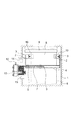
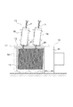
図1は、この発明の実施の形態1によるエレベータを示す側面図である。また、図2は、図1のエレベータ装置を示す平面図である。図において、昇降路1内には、上下方向へ延びる一対のガイドレール2が設置されている。各ガイドレール2は、昇降路1の幅方向(水平方向)について互いに対向している。また、各ガイドレール2は、複数のガイドレール用ブラケット3を介して昇降路1の内壁に固定されている。
Embodiment 1 FIG.
1 is a side view showing an elevator according to Embodiment 1 of the present invention. FIG. 2 is a plan view showing the elevator apparatus of FIG. In the figure, a pair of guide rails 2 extending in the vertical direction are installed in the hoistway 1. The guide rails 2 face each other in the width direction (horizontal direction) of the hoistway 1. Each guide rail 2 is fixed to the inner wall of the hoistway 1 via a plurality of guide rail brackets 3.

各ガイドレール2の上端部間には、プーリブラケット(綱車支持部材)4が固定されている。プーリブラケット4には、昇降路1の幅方向について互いに離して配置された一対の返し車5が設けられている。各返し車5のそれぞれの回転軸は、昇降路1の奥行き方向(即ち、昇降路1の幅方向に垂直な水平方向)に沿って配置されている。各返し車5には、かご6を吊り下げる複数本(この例では、2本)の主索7が巻き掛けられている。主索7としては、例えばロープやベルト等が用いられている。   A pulley bracket (a sheave support member) 4 is fixed between the upper ends of the guide rails 2. The pulley bracket 4 is provided with a pair of return wheels 5 that are arranged apart from each other in the width direction of the hoistway 1. Each rotation shaft of each return wheel 5 is disposed along the depth direction of the hoistway 1 (that is, the horizontal direction perpendicular to the width direction of the hoistway 1). Each return wheel 5 is wound with a plurality of main ropes 7 (two in this example) for suspending a car 6. For example, a rope or a belt is used as the main rope 7.

かご6は、各ガイドレール2間に挟まれた状態で昇降可能になっている。かご6には、図2に示すように、かご出入口8が設けられている。かご6は、かご出入口8の間口方向(幅方向)を昇降路1の幅方向と一致させて昇降路1内に配置されている。かご出入口8は、かごドア装置9により開閉される。かごドア装置9は、かご出入口8の間口方向へ移動可能な複数のかごの戸と、各かごの戸を移動させる駆動力を発生するドア駆動装置とを有している(いずれも図示せず)。かご出入口8は、各かごの戸がかご出入口8の間口方向へ移動することにより開閉される。   The car 6 can be moved up and down while being sandwiched between the guide rails 2. As shown in FIG. 2, the car 6 is provided with a car doorway 8. The car 6 is disposed in the hoistway 1 such that the opening direction (width direction) of the car doorway 8 coincides with the width direction of the hoistway 1. The car doorway 8 is opened and closed by a car door device 9. The car door device 9 includes a plurality of car doors that can move toward the front door of the car doorway 8 and a door drive device that generates a driving force for moving the car doors (all not shown). ). The car doorway 8 is opened and closed as the doors of each car move toward the frontage of the car doorway 8.

かご6の上部及び下部には、ガイドレール2に案内される複数のガイドローラ装置10が設けられている。かご6は、各ガイドローラ装置10がガイドレール2に案内されることにより、各ガイドレール2に沿って昇降される。   A plurality of guide roller devices 10 guided by the guide rail 2 are provided at the upper and lower portions of the car 6. The car 6 is moved up and down along the guide rails 2 when the guide roller devices 10 are guided by the guide rails 2.

昇降路1の下部の側壁には、図1に示すように、昇降路1内と連通する機械室11が設けられている。機械室11には、かご6を昇降させる駆動力を発生する巻胴式巻上機(巻胴式駆動装置)12と、かご6に制動力を与えるためのブレーキ装置13とが設けられている。巻胴式巻上機12及びブレーキ装置13は、図示しない制御装置により制御される。   As shown in FIG. 1, a machine room 11 communicating with the inside of the hoistway 1 is provided on the lower side wall of the hoistway 1. The machine room 11 is provided with a winding cylinder type hoisting machine (winding cylinder type driving device) 12 that generates a driving force for raising and lowering the car 6, and a brake device 13 for applying a braking force to the car 6. . The winding drum type hoisting machine 12 and the brake device 13 are controlled by a control device (not shown).

巻胴式巻上機12は、モータを含む巻上機本体14と、巻上機本体14に設けられ、巻上機本体14の駆動力により回転される巻上機シーブ15とを有している。   The hoisting type hoisting machine 12 includes a hoisting machine main body 14 including a motor, and a hoisting machine sheave 15 that is provided in the hoisting machine main body 14 and is rotated by a driving force of the hoisting machine main body 14. Yes.

各主索7の一端部は、巻上機シーブ15に巻かれている。各主索7の他端部は、シンブルロッド40を介してかご6の上部に接続されている。各主索7は、巻上機シーブ15に巻かれた一端部から、一方の返し車5及び他方の返し車5の順に巻き掛けられ、シンブルロッド40に接続された他端部に達している。   One end of each main rope 7 is wound around a hoisting machine sheave 15. The other end of each main rope 7 is connected to the upper portion of the car 6 via a thimble rod 40. Each main rope 7 is wound from one end wound around the hoisting machine sheave 15 in order of one return wheel 5 and the other return wheel 5, and reaches the other end connected to the thimble rod 40. .

巻胴式巻上機12は、巻上機シーブ15の回転により、巻上機シーブ15に対する主索7の巻き取り・繰り出しを行う。かご6は、巻上機シーブ15に対する主索7の巻き取り・繰り出しが行われることにより、昇降路1内を昇降される。即ち、かご6は、主索7が巻上機シーブ15に巻き取られることにより上昇し、主索7が巻上機シーブ15から繰り出されることにより下降する。この例では、巻胴式巻上機12は、巻上機シーブ15の軸線方向(即ち、巻上機シーブ15の回転軸の軸線方向)を昇降路1の奥行き方向と一致させて機械室11内に配置されている。   The hoisting type hoisting machine 12 winds and unwinds the main rope 7 with respect to the hoisting machine sheave 15 by the rotation of the hoisting machine sheave 15. The car 6 is moved up and down in the hoistway 1 by winding and unwinding the main rope 7 with respect to the hoisting machine sheave 15. That is, the car 6 rises when the main rope 7 is wound around the hoisting machine sheave 15, and descends when the main rope 7 is unwound from the hoisting machine sheave 15. In this example, the hoisting type hoisting machine 12 matches the axial direction of the hoisting machine sheave 15 (that is, the axial direction of the rotating shaft of the hoisting machine sheave 15) with the depth direction of the hoistway 1. Is placed inside.

ブレーキ装置13は、エレベータの運転が正常であるときには制御装置の制御により主索7への制動力の付与を解除している。また、ブレーキ装置13は、エレベータの異常(例えばかご6の過速度等)が制御装置により検出されたときに、制御装置の制御により、主索7に制動力を与える動作を行う。かご6には、主索7がブレーキ装置13によって制動されることにより制動力が与えられる。   The brake device 13 cancels the application of the braking force to the main rope 7 under the control of the control device when the operation of the elevator is normal. The brake device 13 performs an operation of applying a braking force to the main rope 7 under the control of the control device when an abnormality of the elevator (for example, an overspeed of the car 6) is detected by the control device. A braking force is applied to the car 6 when the main rope 7 is braked by the brake device 13.

図3は、図1の巻胴式巻上機12及びブレーキ装置13を示す拡大図である。また、図4は、図3の矢印Aに沿って見たときの巻胴式巻上機12及びブレーキ装置13を示す側面図である。図において、巻上機本体14は、機械室11の床面に設置された機械台に固定されている。巻上機シーブ15は、巻上機本体14に回転自在に支持されている。巻上機シーブ15は、径方向の寸法よりも軸線方向の寸法(即ち、巻上機シーブ15の回転軸に沿った方向の寸法)が大きい筒状体とされている。   FIG. 3 is an enlarged view showing the winding drum type hoisting machine 12 and the brake device 13 of FIG. FIG. 4 is a side view showing the winding drum type hoisting machine 12 and the brake device 13 when viewed along the arrow A in FIG. 3. In the figure, the hoisting machine main body 14 is fixed to a machine base installed on the floor surface of the machine room 11. The hoisting machine sheave 15 is rotatably supported by the hoisting machine main body 14. The hoisting machine sheave 15 is a cylindrical body having a larger dimension in the axial direction (that is, a dimension along the rotation axis of the hoisting machine sheave 15) than the radial dimension.

主索7は、図4に示すように、鉛直線に対して傾斜した状態で巻上機シーブ15に巻かれている。従って、主索7は、巻上機シーブ15の軸線に対しても傾斜した状態で巻上機シーブ15に巻かれている。これにより、巻上機シーブ15に対する主索7の巻き取り・繰り出しは、主索7が巻上機シーブ15の軸線方向へ変位されながら行われる。即ち、巻胴式巻上機12は、巻上機シーブ15の軸線方向へ主索7を変位させながら、巻上機シーブ15に対する主索7の巻き取り・繰り出しを行う。これにより、巻上機シーブ15には、主索7が巻上機シーブ15の軸線方向について均等に巻かれるようになっている。また、巻上機シーブ15から延びる主索7の鉛直線に対する傾斜角度は、巻上機シーブ15に対する主索7の巻き取り・繰り出しが行われるときの巻上機シーブ15の軸線方向への主索7の変位に応じて連続的に変化する。   As shown in FIG. 4, the main rope 7 is wound around the hoisting machine sheave 15 while being inclined with respect to the vertical line. Therefore, the main rope 7 is wound around the hoisting machine sheave 15 in an inclined state with respect to the axis of the hoisting machine sheave 15. As a result, the winding / unwinding of the main rope 7 with respect to the hoisting machine sheave 15 is performed while the main rope 7 is displaced in the axial direction of the hoisting machine sheave 15. That is, the hoisting type hoisting machine 12 winds and unwinds the main rope 7 with respect to the hoisting machine sheave 15 while displacing the main rope 7 in the axial direction of the hoisting machine sheave 15. As a result, the main rope 7 is wound evenly on the hoisting machine sheave 15 in the axial direction of the hoisting machine sheave 15. Further, the inclination angle of the main rope 7 extending from the hoisting machine sheave 15 with respect to the vertical line is such that the main rope 7 in the axial direction of the hoisting machine sheave 15 when the main rope 7 is wound and unwound with respect to the hoisting machine sheave 15. It changes continuously according to the displacement of the cord 7.

ブレーキ装置13は、巻上機シーブ15を避けて配置されている。また、ブレーキ装置13は、巻上機シーブ15の軸線方向へ巻上機シーブ15に対して変位可能なブレーキ装置本体16と、ブレーキ装置本体16を支持し、巻上機シーブ15の軸線方向へ巻上機シーブ15に対してブレーキ装置本体16を案内する案内装置17と、案内装置17を支持し、機械室11の機械台に固定された支持部材18とを有している。   The brake device 13 is arranged avoiding the hoisting machine sheave 15. The brake device 13 supports the brake device main body 16 that can be displaced with respect to the hoisting machine sheave 15 in the axial direction of the hoisting machine sheave 15, and supports the brake device main body 16 in the axial direction of the hoisting machine sheave 15. A guide device 17 that guides the brake device main body 16 with respect to the hoisting machine sheave 15, and a support member 18 that supports the guide device 17 and is fixed to the machine base of the machine room 11.

案内装置17は、支持部材18に固定されたスライドレール19と、ブレーキ装置本体16に取り付けられ、スライドレール19に保持されながら案内されるローラ装置20とを有している。スライドレール19は、巻上機シーブ15の軸線方向に沿って配置されている。ブレーキ装置本体16は、ローラ装置20がスライドレール19に沿って案内されることにより、巻上機シーブ15に対して巻上機シーブ15の軸線方向へ移動される。また、案内装置17は、図4に示すように、巻上機シーブ15の幅寸法(巻上機シーブ15の軸線方向についての巻上機シーブ15の寸法)よりも広い範囲でブレーキ装置本体16を案内可能になっている。案内装置17は、例えばスライド軸とスライド軸をスライドされる軸受とを有する直動式軸受装置(リニアガイド装置)等であってもよい。   The guide device 17 includes a slide rail 19 fixed to the support member 18, and a roller device 20 that is attached to the brake device main body 16 and guided while being held by the slide rail 19. The slide rail 19 is disposed along the axial direction of the hoisting machine sheave 15. The brake device main body 16 is moved in the axial direction of the hoisting machine sheave 15 with respect to the hoisting machine sheave 15 by the roller device 20 being guided along the slide rail 19. Further, as shown in FIG. 4, the guide device 17 has a brake device main body 16 in a wider range than the width dimension of the hoisting machine sheave 15 (the dimension of the hoisting machine sheave 15 in the axial direction of the hoisting machine sheave 15). Can be guided. The guide device 17 may be, for example, a linear motion bearing device (linear guide device) having a slide shaft and a bearing on which the slide shaft is slid.

ブレーキ装置本体16の幅寸法(巻上機シーブ15の軸線方向についてのブレーキ装置本体16の寸法)は、巻上機シーブ15の幅寸法よりも小さくなっている。また、ブレーキ装置本体16は、ローラ装置20が取り付けられた中継ブラケット21と、主索7に接触可能なブレーキヘッド22と、中継ブラケット21とブレーキヘッド22との間に設けられ、中継ブラケット21にブレーキヘッド22を回動自在に取り付ける回動装置23とを有している。   The width of the brake device main body 16 (the size of the brake device main body 16 in the axial direction of the hoisting machine sheave 15) is smaller than the width of the hoisting machine sheave 15. The brake device body 16 is provided between the relay bracket 21 to which the roller device 20 is attached, the brake head 22 that can contact the main rope 7, and the relay bracket 21 and the brake head 22. A rotating device 23 for rotatably mounting the brake head 22 is provided.

回動装置23は、巻上機シーブ15の軸線方向に対して交差し、かつ巻上機シーブ15から延びる主索7にも交差する軸線を持つ回動軸24を有している。この例では、回動軸24が、巻上機シーブ15の軸線方向に対して垂直で、かつ水平に配置された軸とされている。回動軸24の先端部には、ブレーキヘッド22が固定されている。これにより、ブレーキヘッド22は、中継ブラケット21に対して回動軸24の軸線を中心に回動自在になっている。   The rotating device 23 has a rotating shaft 24 that has an axis that intersects the axial direction of the hoisting machine sheave 15 and also intersects the main rope 7 that extends from the hoisting machine sheave 15. In this example, the rotation shaft 24 is a shaft that is perpendicular to the axial direction of the hoisting machine sheave 15 and that is disposed horizontally. A brake head 22 is fixed to the tip of the rotating shaft 24. Thereby, the brake head 22 is rotatable about the axis of the rotation shaft 24 with respect to the relay bracket 21.

ブレーキヘッド22は、巻上機シーブ15の近傍に配置されている。また、ブレーキヘッド22は、図4に示すように、主索7の長さ方向に沿って配置されている。従って、ブレーキヘッド22は、鉛直線に対して傾斜して配置されている。   The brake head 22 is disposed in the vicinity of the hoisting machine sheave 15. Moreover, the brake head 22 is arrange | positioned along the length direction of the main rope 7, as shown in FIG. Therefore, the brake head 22 is disposed to be inclined with respect to the vertical line.

また、ブレーキヘッド22は、主索7を把持する把持装置25と、主索7の長さ方向について互いに離して配置された上側係合装置26及び下側係合装置27(一対の係合装置26,27)と、把持装置25及び各係合装置26,27を支持し、回動軸24に固定された取付枠28とを有している。   The brake head 22 includes a gripping device 25 that grips the main rope 7, and an upper engagement device 26 and a lower engagement device 27 (a pair of engagement devices) that are disposed apart from each other in the length direction of the main rope 7. 26, 27), and a mounting frame 28 that supports the gripping device 25 and the engagement devices 26, 27 and is fixed to the rotating shaft 24.

把持装置25は、上側係合装置26と下側係合装置27との間に配置されている。また、把持装置25は、固定摩擦材29と、固定摩擦材29との間で主索7を把持する把持位置と把持位置よりも固定摩擦材29から離れた解除位置との間で変位可能な可動摩擦材30と、把持位置と解除位置との間で可動摩擦材30を変位させる変位装置とを有している。この例では、図4に示すように、把持装置25が2本の主索7をまとめて把持するようになっている。   The gripping device 25 is disposed between the upper engagement device 26 and the lower engagement device 27. Further, the gripping device 25 is displaceable between the fixed friction material 29 and a grip position where the main rope 7 is gripped between the fixed friction material 29 and a release position farther from the fixed friction material 29 than the grip position. The movable friction material 30 and a displacement device that displaces the movable friction material 30 between the gripping position and the release position are included. In this example, as shown in FIG. 4, the gripping device 25 grips the two main ropes 7 together.

主索7には、固定摩擦材29と可動摩擦材30との間での主索7の把持により制動力が与えられる。また、主索7に与えられる制動力は、固定摩擦材29と可動摩擦材30との間での主索7の把持が解除されることにより消滅する。なお、変位装置は、可動摩擦材30を把持位置へ付勢するばね(付勢体)と、通電により、ばねの付勢力に逆らって可動摩擦材30を解除位置へ変位させる電磁マグネットとを有している。   A braking force is applied to the main rope 7 by gripping the main rope 7 between the fixed friction material 29 and the movable friction material 30. Further, the braking force applied to the main rope 7 disappears when the holding of the main rope 7 between the fixed friction material 29 and the movable friction material 30 is released. The displacement device includes a spring (biasing body) that urges the movable friction material 30 to the gripping position and an electromagnetic magnet that displaces the movable friction material 30 to the release position against energizing force of the spring when energized. is doing.

上側係合装置26及び下側係合装置27のそれぞれは、主索7を挟む一対の挟みローラ31を有している。各挟みローラ31の外周部には、挟みローラ31の周方向へ延びる溝が設けられている。挟みローラ31に設けられる溝としては、例えば断面が円弧状とされた丸溝や、断面がV字状とされたV溝等が挙げられる。主索7は、挟みローラ31に設けられた溝に嵌った状態で各挟みローラ31間に挟まれている。各挟みローラ31は、巻上機シーブ15に対する主索7の巻き取り・繰り出しが行われることにより主索7の移動に応じて回転される。上側係合装置26及び下側係合装置27に対する主索7の移動は、巻上機シーブ15の軸線方向について規制され、主索7の長さ方向についてのみ許容される。各挟みローラ31は、主索7の長さ方向への主索7の移動により、主索7に接触しながら回転される。   Each of the upper engagement device 26 and the lower engagement device 27 has a pair of sandwiching rollers 31 that sandwich the main rope 7. A groove extending in the circumferential direction of the sandwiching roller 31 is provided on the outer peripheral portion of each sandwiching roller 31. As a groove | channel provided in the pinching roller 31, the round groove by which the cross section was made into circular arc shape, the V groove by which the cross section was made into V shape, etc. are mentioned, for example. The main rope 7 is sandwiched between the respective sandwiching rollers 31 in a state of being fitted in a groove provided in the sandwiching roller 31. Each pinching roller 31 is rotated according to the movement of the main rope 7 by winding and unwinding the main rope 7 with respect to the hoisting machine sheave 15. The movement of the main rope 7 with respect to the upper engagement device 26 and the lower engagement device 27 is restricted in the axial direction of the hoisting machine sheave 15 and is allowed only in the length direction of the main rope 7. Each pinching roller 31 is rotated while contacting the main rope 7 by the movement of the main rope 7 in the length direction of the main rope 7.

上側係合装置26及び下側係合装置27は、巻上機シーブ15に対する主索7の巻き取り・繰り出しが行われるときに、巻上機シーブ15の軸線方向へ変位される主索7によって押される。ブレーキ装置本体16は、巻上機シーブ15の軸線方向へ変位される主索7によって上側係合装置26及び下側係合装置27が押されることにより、案内装置17に案内されながら、主索7の変位に合わせて変位される。   The upper engaging device 26 and the lower engaging device 27 are moved by the main rope 7 that is displaced in the axial direction of the hoisting machine sheave 15 when the main rope 7 is wound and unwound from the hoisting machine sheave 15. Pressed. The brake device main body 16 is guided by the guide device 17 while the upper engagement device 26 and the lower engagement device 27 are pushed by the main rope 7 displaced in the axial direction of the hoisting machine sheave 15. It is displaced according to the displacement of 7.

鉛直線に対する主索7の傾斜角度が変化すると、上側係合装置26及び下側係合装置27が互いに異なる位置で主索7によって押されるので、ブレーキヘッド22を回動させる力がブレーキヘッド22に与えられる。これにより、ブレーキヘッド22が回動軸24の軸線を中心に回動され、ブレーキヘッド22の傾斜角度が、主索7の傾斜角度の変化に追従して変化する。即ち、回動装置23は、回動軸24を中心にブレーキヘッド22を回動させて鉛直線に対する主索7の傾斜角度の変化にブレーキヘッド22を追従させる機能を持っている。   When the inclination angle of the main rope 7 with respect to the vertical line changes, the upper engagement device 26 and the lower engagement device 27 are pushed by the main rope 7 at different positions, so that the force for rotating the brake head 22 is the brake head 22. Given to. As a result, the brake head 22 is rotated about the axis of the rotation shaft 24, and the inclination angle of the brake head 22 changes following the change in the inclination angle of the main rope 7. That is, the rotation device 23 has a function of causing the brake head 22 to follow the change in the inclination angle of the main rope 7 with respect to the vertical line by rotating the brake head 22 about the rotation shaft 24.

例えば、主索7が巻上機シーブ15から繰り出されることにより、ブレーキヘッド22の位置における主索7の傾斜角度が小さくなると、ブレーキヘッド22の傾斜角度θも、図4に示すように、主索7の傾斜角度の変化に追従してθ1からθ2(θ1>θ2)へ小さくなるように変化する。   For example, when the main rope 7 is drawn out from the hoisting machine sheave 15 and the inclination angle of the main rope 7 at the position of the brake head 22 is reduced, the inclination angle θ of the brake head 22 is also increased as shown in FIG. Following the change in the inclination angle of the cord 7, the angle changes from θ1 to θ2 (θ1> θ2).

次に、動作について説明する。エレベータの異常が検出されていない通常時には、把持装置25による主索7の把持が解除されている。このときには、巻上機シーブ15に対する主索7の巻き取り・繰り出しにより、かご6が昇降可能になっている。   Next, the operation will be described. At normal times when no abnormality in the elevator is detected, the gripping of the main rope 7 by the gripping device 25 is released. At this time, the car 6 can be raised and lowered by winding and unwinding the main rope 7 with respect to the hoisting machine sheave 15.

巻胴式巻上機12の駆動力によりかご6が昇降路1内を昇降されるときには、主索7が巻上機シーブ15の軸線方向へ変位されながら、巻上機シーブ15に対する主索7の巻き取り・繰り出しが行われる。このとき、ブレーキ装置本体16は、主索7に押されながら案内装置17に案内され、巻上機シーブ15の軸線方向へ主索7の変位に合わせて変位される。   When the car 6 is raised and lowered in the hoistway 1 by the driving force of the hoisting type hoisting machine 12, the main rope 7 with respect to the hoisting machine sheave 15 is displaced while the main rope 7 is displaced in the axial direction of the hoisting machine sheave 15. Is taken up and fed out. At this time, the brake device body 16 is guided by the guide device 17 while being pushed by the main rope 7, and is displaced in the axial direction of the hoisting machine sheave 15 according to the displacement of the main rope 7.

また、主索7が巻上機シーブ15の軸線方向へ変位されながら、巻上機シーブ15に対する主索7の巻き取り・繰り出しが行われると、ブレーキヘッド22の位置における主索7の傾斜角度が、巻上機シーブ15の軸線方向への主索7の変位に応じて変化する。このとき、上側係合装置26及び下側係合装置27が主索7に押されるので、ブレーキヘッド22は、主索7の傾斜角度の変化に追従して回動軸24を中心に回動される。これにより、主索7に対するブレーキヘッド22の姿勢が主索7の長さ方向に沿った状態に保たれる。   Further, when the main rope 7 is wound and unwound with respect to the hoisting machine sheave 15 while the main rope 7 is displaced in the axial direction of the hoisting machine sheave 15, the inclination angle of the main rope 7 at the position of the brake head 22. However, it changes according to the displacement of the main rope 7 in the axial direction of the hoisting machine sheave 15. At this time, since the upper engagement device 26 and the lower engagement device 27 are pushed by the main rope 7, the brake head 22 rotates around the rotation shaft 24 following the change in the inclination angle of the main rope 7. Is done. Thereby, the posture of the brake head 22 with respect to the main rope 7 is maintained in a state along the length direction of the main rope 7.

例えばかご6の速度が異常に高くなってかご6の過速度が制御装置により検出されたときには、制御装置の制御により把持装置25が動作され、主索7が把持装置25により把持される。これにより、主索7に制動力が与えられ、かご6が減速される。   For example, when the speed of the car 6 is abnormally high and the overspeed of the car 6 is detected by the control device, the gripping device 25 is operated by the control of the control device, and the main rope 7 is gripped by the gripping device 25. As a result, a braking force is applied to the main rope 7 and the car 6 is decelerated.

このようなエレベータのブレーキ装置13では、巻上機シーブ15の軸線方向へ変位される主索7によって上側係合装置26及び下側係合装置27が押されることにより、ブレーキ装置本体16が案内装置17に案内されながら主索7の変位に合わせて変位されるので、主索7を把持する把持装置25の幅寸法を巻上機シーブ15の幅寸法の全範囲に設定する必要がなくなり、把持装置25の大形化を抑制することができる。従って、巻胴式巻上機12を有するエレベータにブレーキ装置13を適用した場合であっても、例えば各主索7をまとめた幅寸法と同程度の幅寸法にまで把持装置25の小形化を図ることができる。これにより、ブレーキ装置13の製造コストの低減化を図ることができる。また、例えば、ブレーキ装置13の据付や保守点検、あるいは把持装置25の調整(例えば固定摩擦材29及び可動摩擦材30間の隙間の調整)等の作業を容易にすることができる。   In such an elevator brake device 13, the upper engagement device 26 and the lower engagement device 27 are pushed by the main rope 7 displaced in the axial direction of the hoisting machine sheave 15, whereby the brake device body 16 is guided. Since it is displaced according to the displacement of the main rope 7 while being guided by the device 17, it is not necessary to set the width dimension of the gripping device 25 for gripping the main rope 7 to the entire range of the width dimension of the hoisting machine sheave 15. An increase in size of the gripping device 25 can be suppressed. Therefore, even when the brake device 13 is applied to an elevator having the hoisting type hoisting machine 12, for example, the gripping device 25 can be reduced in size to the same width as the combined width of the main ropes 7. Can be planned. Thereby, the manufacturing cost of the brake device 13 can be reduced. Further, for example, work such as installation and maintenance inspection of the brake device 13 or adjustment of the gripping device 25 (for example, adjustment of a gap between the fixed friction material 29 and the movable friction material 30) can be facilitated.

また、上側係合装置26及び下側係合装置27のそれぞれは、主索7を挟む一対の挟みローラ31を有し、主索7が嵌る溝が各挟みローラ31の外周部に設けられているので、各挟みローラ31を回転させながら主索7を円滑に移動させることができる。また、上側係合装置26、下側係合装置27及び主索7における摩耗の発生を抑制することができ、主索7及びブレーキ装置13の長寿命化も図ることができる。   Each of the upper engagement device 26 and the lower engagement device 27 has a pair of sandwiching rollers 31 that sandwich the main rope 7, and a groove in which the main rope 7 is fitted is provided on the outer peripheral portion of each sandwiching roller 31. Therefore, the main rope 7 can be smoothly moved while rotating the respective pinching rollers 31. Further, the occurrence of wear in the upper engagement device 26, the lower engagement device 27, and the main rope 7 can be suppressed, and the life of the main rope 7 and the brake device 13 can be extended.

また、ブレーキ装置本体16は、巻上機シーブ15の軸線方向に交差する回動軸24を中心にブレーキヘッド22を回動させて鉛直線に対する主索7の傾斜角度の変化にブレーキヘッド22を追従させる回動装置23を有しているので、主索7の傾斜角度が変化しても、ブレーキヘッド22の姿勢を主索7に対して一定に保つことができ、把持装置25による主索7の把持によって主索7に制動力をより確実にかつ安定的に与えることができる。   Further, the brake device main body 16 rotates the brake head 22 around a rotation shaft 24 intersecting with the axial direction of the hoisting machine sheave 15 to change the inclination angle of the main rope 7 with respect to the vertical line. Since the follower turning device 23 is provided, the posture of the brake head 22 can be kept constant with respect to the main rope 7 even if the inclination angle of the main rope 7 changes, and the main rope by the holding device 25 can be maintained. By gripping 7, the braking force can be applied to the main rope 7 more reliably and stably.

実施の形態2.
実施の形態1では、ブレーキ装置本体16の数が1つとなっているが、ブレーキ装置本体16の数を複数にしてもよい。
Embodiment 2. FIG.
In the first embodiment, the number of brake device main bodies 16 is one, but the number of brake device main bodies 16 may be plural.

即ち、図5は、この発明の実施の形態2によるエレベータの巻胴式巻上機及びブレーキ装置を示す側面図である。図において、巻胴式巻上機12の巻上機シーブ15には、複数本(この例では、2本)の主索7がまとまった複数組(この例では、2組)の主索群が巻かれている。ブレーキ装置13は、各主索群に対応する複数(この例では、2つ)のブレーキ装置本体16と、巻上機シーブ15の軸線方向へ巻上機シーブ15に対して各ブレーキ装置本体16を案内する共通の案内装置17と、案内装置17を支持する実施の形態1と同様の支持部材18とを有している。   5 is a side view showing an elevator hoist type hoisting machine and a brake device according to Embodiment 2 of the present invention. In the figure, the hoisting sheave 15 of the hoisting type hoisting machine 12 has a plurality of sets (two sets in this example) of main ropes 7 (two sets in this example). Is wound. The brake device 13 includes a plurality (two in this example) of brake device main bodies 16 corresponding to each main rope group, and each brake device main body 16 with respect to the hoisting machine sheave 15 in the axial direction of the hoisting machine sheave 15. And a support member 18 similar to the first embodiment for supporting the guide device 17.

案内装置17は、巻上機シーブ15の軸線方向に沿って配置された共通のスライドレール19と、各ブレーキ装置本体16に個別に設けられ、スライドレール19に保持されながら案内される複数(この例では、2つ)のローラ装置20とを有している。実施の形態2の案内装置17の他の構成は、実施の形態1の案内装置17の構成と同様である。   The guide device 17 is provided on a common slide rail 19 disposed along the axial direction of the hoisting machine sheave 15 and a plurality of brake device main bodies 16 and guided while being held by the slide rail 19 (this In the example, two roller devices 20 are provided. Other configurations of the guide device 17 according to the second embodiment are the same as those of the guide device 17 according to the first embodiment.

各ブレーキ装置本体16のそれぞれの構成は、実施の形態1のブレーキ装置本体16の構成と同様である。各ブレーキ装置本体16は、把持装置25による主索群の把持により、各主索群に対して個別に制動力を与える。即ち、各ブレーキ装置本体16は、巻上機シーブ15に対する巻き取り・繰り出しが行われる複数本の主索7のうち、互いに異なる主索7に制動力を個別に与える。また、各ブレーキ装置本体16は、巻上機シーブ15の軸線方向へ変位される各主索群によって個別に押されることにより、案内装置17により案内されながら、主索群の変位に合わせて個別に変位される。さらに、各ブレーキヘッド22は、各回動軸24を中心に個別に回動されながら、鉛直線に対する各主索群の傾斜角度の変化に個別に追従する。他の構成は実施の形態1と同様である。   The configuration of each brake device main body 16 is the same as the configuration of the brake device main body 16 of the first embodiment. Each brake device main body 16 gives a braking force to each main rope group individually by holding the main rope group by the holding device 25. That is, each brake device main body 16 individually applies a braking force to the different main ropes 7 among the plurality of main ropes 7 that are wound and unwound from the hoisting machine sheave 15. Each brake device body 16 is individually pushed in accordance with the displacement of the main rope group while being guided by the guide device 17 by being individually pushed by each main rope group displaced in the axial direction of the hoisting machine sheave 15. Is displaced. Further, each brake head 22 individually follows the change in the inclination angle of each main cord group with respect to the vertical line while being individually rotated about each rotation axis 24. Other configurations are the same as those in the first embodiment.

このようなエレベータのブレーキ装置13では、複数の主索7のうち、互いに異なる主索7に制動力を個別に与える複数のブレーキ装置本体16が共通の案内装置17により案内されるので、例えばかご6の積載重量が大きくなって主索7の本数が増えた場合であっても、ブレーキ装置13の大形化を抑制することができるとともに、各主索7に制動力をより確実に与えることができる。   In such an elevator brake device 13, among the plurality of main ropes 7, a plurality of brake device bodies 16 that individually apply braking force to the different main ropes 7 are guided by the common guide device 17. Even when the load weight of 6 increases and the number of main ropes 7 increases, the size of the brake device 13 can be suppressed and the braking force can be more reliably applied to each main rope 7. Can do.

なお、各上記実施の形態では、巻上機シーブ15の軸線方向へ変位される主索7によって押される係合装置の数が上側係合装置26及び下側係合装置27の2つとなっているが、これに限定されず、係合装置の数を1つとしてもよいし、3つ以上としてもよい。   In each of the above embodiments, the number of the engagement devices pushed by the main rope 7 displaced in the axial direction of the hoisting machine sheave 15 is two, that is, the upper engagement device 26 and the lower engagement device 27. However, the present invention is not limited to this, and the number of engaging devices may be one, or may be three or more.

また、各上記実施の形態では、上側係合装置26及び下側係合装置27のそれぞれが主索7を挟む一対の挟みローラ31を有しているが、係合装置は、主索7に押されてブレーキヘッド22とともに変位されるものであればよく、例えば主索7を挟む板状部材や主索7が内部を通る筒状部材等を係合装置としてもよい。   Further, in each of the above embodiments, each of the upper engagement device 26 and the lower engagement device 27 has a pair of pinching rollers 31 that sandwich the main rope 7, but the engagement device is attached to the main rope 7. Any member that can be pushed and displaced together with the brake head 22 may be used. For example, a plate-like member that sandwiches the main rope 7 or a cylindrical member that passes through the main rope 7 may be used as the engagement device.

また、各上記実施の形態では、主索7を挟む一対の挟みローラ31のそれぞれの外周部に、主索7が嵌る溝が設けられているが、一対の挟みローラ31のいずれか一方の外周部のみに、主索7が嵌る溝を設けてもよい。   Moreover, in each said embodiment, although the groove | channel where the main rope 7 fits is provided in each outer peripheral part of a pair of pinching roller 31 which pinches | interposes the main rope 7, the outer periphery of either one of a pair of pinching rollers 31 is provided. You may provide the groove | channel in which the main rope 7 fits only in a part.

また、各上記実施の形態では、ブレーキヘッド22と中継ブラケット21との間に回動装置23が設けられているが、ブレーキヘッド22の傾斜角度を変化させなくても、案内装置17の案内により巻上機シーブ15の軸線方向へブレーキ装置本体16を主索7の変位に合わせて変位させることができるので、回動装置23はなくてもよい。   Further, in each of the above embodiments, the rotation device 23 is provided between the brake head 22 and the relay bracket 21. However, even if the inclination angle of the brake head 22 is not changed, it is guided by the guide device 17. Since the brake device main body 16 can be displaced in accordance with the displacement of the main rope 7 in the axial direction of the hoisting machine sheave 15, the rotating device 23 is not necessary.

6 かご、7 主索、12 巻胴式巻上機、13 ブレーキ装置(エレベータのブレーキ装置)、15 巻上機シーブ、16 ブレーキ装置本体、17 案内装置、22 ブレーキヘッド、23 回動装置、25 把持装置、26 上側係合装置(係合装置)、27 下側係合装置(係合装置)、31 挟みローラ。   6 car, 7 main rope, 12 hoist type hoisting machine, 13 brake device (elevator brake device), 15 hoisting machine sheave, 16 brake device main body, 17 guide device, 22 brake head, 23 rotating device, 25 Gripping device, 26 upper engagement device (engagement device), 27 lower engagement device (engagement device), 31 pinching roller.

Claims (4)

かごを吊り下げる主索を巻上機シーブの軸線方向へ変位させながら上記巻上機シーブに対する上記主索の巻き取り・繰り出しを行って上記かごを昇降させる巻胴式巻上機を有するエレベータに設けられたエレベータのブレーキ装置であって、
上記主索を把持して上記主索に制動力を与える把持装置と、上記巻上機シーブの軸線方向へ変位される上記主索によって押される係合装置とを含むブレーキヘッドを有するブレーキ装置本体、及び
上記巻上機シーブの軸線方向へ上記巻上機シーブに対して上記ブレーキ装置本体を案内する案内装置
を備え、
上記ブレーキ装置本体は、上記巻上機シーブの軸線方向へ変位される上記主索によって上記係合装置が押されることにより、上記案内装置に案内されながら、上記主索の変位に合わせて変位されることを特徴とするエレベータのブレーキ装置。
To an elevator having a hoisting type hoisting machine that moves up and down the car by winding and unwinding the main rope with respect to the hoisting machine sheave while displacing the main rope that suspends the car in the axial direction of the hoisting machine sheave An elevator brake device provided,
Brake device body having a brake head including a gripping device that grips the main rope and applies a braking force to the main rope, and an engagement device that is pushed by the main rope that is displaced in the axial direction of the hoisting machine sheave And a guide device for guiding the brake device main body with respect to the hoisting machine sheave in the axial direction of the hoisting machine sheave,
The brake device main body is displaced in accordance with the displacement of the main rope while being guided by the guide device when the engagement device is pushed by the main rope displaced in the axial direction of the hoisting machine sheave. An elevator brake device.
上記係合装置は、上記主索を挟む一対の挟みローラを有し、
各上記挟みローラの少なくともいずれかの外周部には、上記主索が嵌る溝が設けられていることを特徴とする請求項1に記載のエレベータのブレーキ装置。
The engagement device has a pair of sandwiching rollers that sandwich the main rope,
The elevator brake device according to claim 1, wherein a groove into which the main rope is fitted is provided in at least one outer peripheral portion of each of the pinching rollers.
上記ブレーキヘッドの位置では、上記巻上機シーブに対する上記主索の巻き取り・繰り出しにより、鉛直線に対する上記主索の傾斜角度が変化するようになっており、
上記ブレーキヘッドは、上記主索の長さ方向について互いに離して配置された一対の上記係合装置を有し、
上記ブレーキ装置本体は、上記巻上機シーブの軸線方向に対して交差する方向へ延びる回動軸を中心に上記ブレーキヘッドを回動させて上記鉛直線に対する上記主索の傾斜角度の変化に上記ブレーキヘッドを追従させる回動装置をさらに有していることを特徴とする請求項1又は請求項2に記載のエレベータのブレーキ装置。
At the position of the brake head, the inclination angle of the main rope with respect to the vertical line is changed by winding and unwinding the main rope with respect to the hoist sheave.
The brake head has a pair of engaging devices arranged apart from each other in the length direction of the main rope,
The brake device main body rotates the brake head around a rotation axis extending in a direction intersecting the axial direction of the hoist sheave to change the inclination angle of the main rope with respect to the vertical line. The elevator braking device according to claim 1, further comprising a rotation device that causes the brake head to follow.
上記巻上機シーブに対する巻き取り・繰り出しが行われる複数の上記主索のうち、互いに異なる上記主索に制動力を個別に与える複数の上記ブレーキ装置本体を備え、
各上記ブレーキ装置本体は、共通の上記案内装置により案内されることを特徴とする請求項1乃至請求項3のいずれか一項に記載のエレベータのブレーキ装置。
Among the plurality of main ropes that are wound and unwound with respect to the hoisting machine sheave, comprising a plurality of brake device bodies that individually apply braking force to the different main ropes,
4. The elevator brake device according to claim 1, wherein each of the brake device main bodies is guided by the common guide device. 5.
JP2011010830A 2011-01-21 2011-01-21 Brake device of elevator Withdrawn JP2012148882A (en)

Priority Applications (1)

Application Number Priority Date Filing Date Title
JP2011010830A JP2012148882A (en) 2011-01-21 2011-01-21 Brake device of elevator

Applications Claiming Priority (1)

Application Number Priority Date Filing Date Title
JP2011010830A JP2012148882A (en) 2011-01-21 2011-01-21 Brake device of elevator

Publications (1)

Publication Number Publication Date
JP2012148882A true JP2012148882A (en) 2012-08-09

Family

ID=46791563

Family Applications (1)

Application Number Title Priority Date Filing Date
JP2011010830A Withdrawn JP2012148882A (en) 2011-01-21 2011-01-21 Brake device of elevator

Country Status (1)

Country Link
JP (1) JP2012148882A (en)

Cited By (1)

* Cited by examiner, † Cited by third party
Publication number Priority date Publication date Assignee Title
CN103264940A (en) * 2013-06-05 2013-08-28 中国水利水电第七工程局有限公司 Drum type safe suspension cage

Cited By (1)

* Cited by examiner, † Cited by third party
Publication number Priority date Publication date Assignee Title
CN103264940A (en) * 2013-06-05 2013-08-28 中国水利水电第七工程局有限公司 Drum type safe suspension cage

Similar Documents

Publication Publication Date Title
JP5460715B2 (en) Elevator equipment
EP2017213B1 (en) Safety device for elevator
JP5502234B2 (en) Double deck elevator
JP2012148882A (en) Brake device of elevator
EP3142955B1 (en) Traction geared machine for elevator
JP5623794B2 (en) Back tension applying device for winding wire and method for applying back tension
JPWO2007138706A1 (en) Elevator equipment
US20160257529A1 (en) Elevator drive
JP6289743B2 (en) Elevator equipment
US11453572B2 (en) Space saving arrangement of a machine-room-less elevator device
KR101054013B1 (en) Traction machine for elevator
JPWO2021124481A5 (en)
JP5191825B2 (en) Self-propelled elevator
JP6694598B2 (en) Double deck elevator and its driving method
WO2006043317A1 (en) Elevator apparatus
KR20150001635U (en) Machine room-less elevator
EP2876074A1 (en) Elevator drive
JP2012091938A (en) Safety device of elevator
WO2020044550A1 (en) Elevator
US20190270615A1 (en) Method and arrangement
JP2016222430A (en) Cage movement inhibitor of elevator
KR101398621B1 (en) Elevator
JP5846811B2 (en) Elevator lifting body
JP2013227133A (en) Elevator device and floor landing error correction method thereof
JP2016155643A (en) Elevator device

Legal Events

Date Code Title Description
A300 Withdrawal of application because of no request for examination

Free format text: JAPANESE INTERMEDIATE CODE: A300

Effective date: 20140401