EP4234448B1 - Bürstengliederband zum transport von vorformlingen - Google Patents
Bürstengliederband zum transport von vorformlingen Download PDFInfo
- Publication number
- EP4234448B1 EP4234448B1 EP23176452.3A EP23176452A EP4234448B1 EP 4234448 B1 EP4234448 B1 EP 4234448B1 EP 23176452 A EP23176452 A EP 23176452A EP 4234448 B1 EP4234448 B1 EP 4234448B1
- Authority
- EP
- European Patent Office
- Prior art keywords
- preforms
- brushes
- transport device
- neck
- guide
- Prior art date
- Legal status (The legal status is an assumption and is not a legal conclusion. Google has not performed a legal analysis and makes no representation as to the accuracy of the status listed.)
- Active
Links
Images


Classifications
-
- B—PERFORMING OPERATIONS; TRANSPORTING
- B65—CONVEYING; PACKING; STORING; HANDLING THIN OR FILAMENTARY MATERIAL
- B65G—TRANSPORT OR STORAGE DEVICES, e.g. CONVEYORS FOR LOADING OR TIPPING, SHOP CONVEYOR SYSTEMS OR PNEUMATIC TUBE CONVEYORS
- B65G15/00—Conveyors having endless load-conveying surfaces, i.e. belts and like continuous members, to which tractive effort is transmitted by means other than endless driving elements of similar configuration
- B65G15/10—Conveyors having endless load-conveying surfaces, i.e. belts and like continuous members, to which tractive effort is transmitted by means other than endless driving elements of similar configuration comprising two or more co-operating endless surfaces with parallel longitudinal axes, or a multiplicity of parallel elements, e.g. ropes defining an endless surface
- B65G15/12—Conveyors having endless load-conveying surfaces, i.e. belts and like continuous members, to which tractive effort is transmitted by means other than endless driving elements of similar configuration comprising two or more co-operating endless surfaces with parallel longitudinal axes, or a multiplicity of parallel elements, e.g. ropes defining an endless surface with two or more endless belts
- B65G15/14—Conveyors having endless load-conveying surfaces, i.e. belts and like continuous members, to which tractive effort is transmitted by means other than endless driving elements of similar configuration comprising two or more co-operating endless surfaces with parallel longitudinal axes, or a multiplicity of parallel elements, e.g. ropes defining an endless surface with two or more endless belts the load being conveyed between the belts
-
- B—PERFORMING OPERATIONS; TRANSPORTING
- B65—CONVEYING; PACKING; STORING; HANDLING THIN OR FILAMENTARY MATERIAL
- B65G—TRANSPORT OR STORAGE DEVICES, e.g. CONVEYORS FOR LOADING OR TIPPING, SHOP CONVEYOR SYSTEMS OR PNEUMATIC TUBE CONVEYORS
- B65G15/00—Conveyors having endless load-conveying surfaces, i.e. belts and like continuous members, to which tractive effort is transmitted by means other than endless driving elements of similar configuration
- B65G15/10—Conveyors having endless load-conveying surfaces, i.e. belts and like continuous members, to which tractive effort is transmitted by means other than endless driving elements of similar configuration comprising two or more co-operating endless surfaces with parallel longitudinal axes, or a multiplicity of parallel elements, e.g. ropes defining an endless surface
- B65G15/105—Conveyors having endless load-conveying surfaces, i.e. belts and like continuous members, to which tractive effort is transmitted by means other than endless driving elements of similar configuration comprising two or more co-operating endless surfaces with parallel longitudinal axes, or a multiplicity of parallel elements, e.g. ropes defining an endless surface the surface being formed by two or more ropes
-
- B—PERFORMING OPERATIONS; TRANSPORTING
- B65—CONVEYING; PACKING; STORING; HANDLING THIN OR FILAMENTARY MATERIAL
- B65G—TRANSPORT OR STORAGE DEVICES, e.g. CONVEYORS FOR LOADING OR TIPPING, SHOP CONVEYOR SYSTEMS OR PNEUMATIC TUBE CONVEYORS
- B65G15/00—Conveyors having endless load-conveying surfaces, i.e. belts and like continuous members, to which tractive effort is transmitted by means other than endless driving elements of similar configuration
- B65G15/60—Arrangements for supporting or guiding belts, e.g. by fluid jets
-
- B—PERFORMING OPERATIONS; TRANSPORTING
- B65—CONVEYING; PACKING; STORING; HANDLING THIN OR FILAMENTARY MATERIAL
- B65G—TRANSPORT OR STORAGE DEVICES, e.g. CONVEYORS FOR LOADING OR TIPPING, SHOP CONVEYOR SYSTEMS OR PNEUMATIC TUBE CONVEYORS
- B65G51/00—Conveying articles through pipes or tubes by fluid flow or pressure; Conveying articles over a flat surface, e.g. the base of a trough, by jets located in the surface
- B65G51/02—Directly conveying the articles, e.g. slips, sheets, stockings, containers or workpieces, by flowing gases
- B65G51/03—Directly conveying the articles, e.g. slips, sheets, stockings, containers or workpieces, by flowing gases over a flat surface or in troughs
- B65G51/035—Directly conveying the articles, e.g. slips, sheets, stockings, containers or workpieces, by flowing gases over a flat surface or in troughs for suspended articles, e.g. bottles
-
- B—PERFORMING OPERATIONS; TRANSPORTING
- B65—CONVEYING; PACKING; STORING; HANDLING THIN OR FILAMENTARY MATERIAL
- B65G—TRANSPORT OR STORAGE DEVICES, e.g. CONVEYORS FOR LOADING OR TIPPING, SHOP CONVEYOR SYSTEMS OR PNEUMATIC TUBE CONVEYORS
- B65G15/00—Conveyors having endless load-conveying surfaces, i.e. belts and like continuous members, to which tractive effort is transmitted by means other than endless driving elements of similar configuration
- B65G15/22—Conveyors having endless load-conveying surfaces, i.e. belts and like continuous members, to which tractive effort is transmitted by means other than endless driving elements of similar configuration comprising a series of co-operating units
- B65G15/26—Conveyors having endless load-conveying surfaces, i.e. belts and like continuous members, to which tractive effort is transmitted by means other than endless driving elements of similar configuration comprising a series of co-operating units extensible, e.g. telescopic
-
- B—PERFORMING OPERATIONS; TRANSPORTING
- B65—CONVEYING; PACKING; STORING; HANDLING THIN OR FILAMENTARY MATERIAL
- B65G—TRANSPORT OR STORAGE DEVICES, e.g. CONVEYORS FOR LOADING OR TIPPING, SHOP CONVEYOR SYSTEMS OR PNEUMATIC TUBE CONVEYORS
- B65G19/00—Conveyors comprising an impeller or a series of impellers carried by an endless traction element and arranged to move articles or materials over a supporting surface or underlying material, e.g. endless scraper conveyors
- B65G19/02—Conveyors comprising an impeller or a series of impellers carried by an endless traction element and arranged to move articles or materials over a supporting surface or underlying material, e.g. endless scraper conveyors for articles, e.g. for containers
- B65G19/025—Conveyors comprising an impeller or a series of impellers carried by an endless traction element and arranged to move articles or materials over a supporting surface or underlying material, e.g. endless scraper conveyors for articles, e.g. for containers for suspended articles
-
- B—PERFORMING OPERATIONS; TRANSPORTING
- B65—CONVEYING; PACKING; STORING; HANDLING THIN OR FILAMENTARY MATERIAL
- B65G—TRANSPORT OR STORAGE DEVICES, e.g. CONVEYORS FOR LOADING OR TIPPING, SHOP CONVEYOR SYSTEMS OR PNEUMATIC TUBE CONVEYORS
- B65G2201/00—Indexing codes relating to handling devices, e.g. conveyors, characterised by the type of product or load being conveyed or handled
-
- B—PERFORMING OPERATIONS; TRANSPORTING
- B65—CONVEYING; PACKING; STORING; HANDLING THIN OR FILAMENTARY MATERIAL
- B65G—TRANSPORT OR STORAGE DEVICES, e.g. CONVEYORS FOR LOADING OR TIPPING, SHOP CONVEYOR SYSTEMS OR PNEUMATIC TUBE CONVEYORS
- B65G2207/00—Indexing codes relating to constructional details, configuration and additional features of a handling device, e.g. Conveyors
- B65G2207/42—Soft elements to prevent damage to articles, e.g. bristles, foam
Definitions
- the invention relates to the transport of articles, and more particularly to the transport of container preforms made of plastic material such as PET.
- a preform generally comprises a tubular body closed at a lower end by a hemispherical bottom, and a neck, usually threaded, which extends the body from an upper end thereof. Most preforms are also provided with a collar which separates the neck from the body and which facilitates the handling of the preforms.
- a manufacturing cycle of a container requires numerous handling operations of the preform from which the container is intended to be manufactured. From a bulk packaging in a hopper (or a bowl, or any other container), the preform is successively extracted from the hopper, oriented (neck up or neck down), transferred to a heating unit (or oven), conveyed in the latter to undergo thermal conditioning, then again transferred to a mold to be transformed into a container by blow molding or stretch blow molding.
- a heating unit or oven
- the speed of transport of the preforms during such a cycle is not constant.
- the bulk packaging of the preforms in the hopper or bowl does not allow the heating unit to be fed directly at the outlet thereof. Consequently, an intermediate zone is provided between the hopper and the heating unit where the preforms are temporarily accumulated to allow continuous feeding of the heating unit.
- a transport device is usually used with an endless belt which drives the preforms by friction, along a predetermined path (which can be at least locally linear).
- the French patent FR 2 956 652 or its American equivalent US 2012/312661 (SIDEL PARTICIPATIONS ) describes a conveyor equipped with two endless belts, at least one of which comprises, at an active part in contact with the preforms, a natural material consisting of leather.
- IT MO20 090 60 A1 discloses a transport device according to the preamble of claim 1.
- a first objective of the invention is to propose a preform transport device which allows efficient accumulation of the preforms.
- a second objective of the invention is to propose a preform transport device which has better wear resistance.
- a third objective of the invention is to provide a transport device which offers better resistance to heating.
- a device for transporting preforms of plastic containers, this device comprising at least one endless circulating element having an external face and carrying a series of brushes which extend projecting from the external face, capable of coming into contact with the preforms to drive them by friction along a path, this device further comprising a fixed support defining a flat support face for the preforms.
- the brushes efficiently drive the preforms by friction of the ends of their bristles. This friction generates little or no dust (and therefore little pollution), and the wear of the brushes remains slow when the chosen material (for example a Nylon ® ) is resistant to wear by friction.
- each preform has a tubular wall defining a body and a neck separated by a collar which projects radially from the wall
- the device comprises a pair of rails spaced apart from each other, which define jointly at least part of the path of the preforms, these rails having coplanar support faces for the suspension by their collar of the preforms oriented neck upwards.
- At least a portion of the brushes may extend under the rails to contact the body of the preforms.
- the device comprises for example a neck guide which extends directly above the rails at a distance from them greater than or equal to a height of the neck of the preforms;
- the device comprises a plate forming a support for the preforms oriented neck down, and the brushes extend above the plate.
- the device may comprise a bottom guide which extends directly above the plate, at a distance from the latter greater than or equal to an overall height of the preforms.
- the device comprises, for example, two circulating elements equipped with brushes and having, along the path, parallel strands to jointly drive the preforms by friction.
- the device may further comprise, over at least part of the path, a lateral guide against which the circulating element rests by an internal face opposite the external face.
- each brush includes, for example, a row of superimposed tufts of bristles.
- each circulating element can include brushes along its entire length.
- a device 1 for transporting (or conveyor) preforms 2 of containers made of plastic material, for example polyethylene terephthalate (PET).
- PET polyethylene terephthalate
- Each preform 2 has a tubular side wall 3 defining a body 4 and a neck 5.
- the body 4 ends, at an end opposite the neck 5, with a hemispherical bottom 6.
- the neck 5 forms a rim 7 through which the container is intended to be filled.
- the neck 5 can be threaded to allow the screwing of a cap after this filling.
- each preform 2 further has an annular collar 8 used to facilitate the handling of the preforms 2 (and also of the containers formed from these preforms 2).
- the collar 8 extends to the junction between the body 4 and the neck 5, but this configuration is not limiting.
- the collar could extend to an end opposite the bottom 6, so as to form the rim of the container.
- the neck 5 is optional, so that the preform could be limited to a smooth body terminated at one end by a bottom and, at an opposite end, by a collar.
- the collar 8 is not necessarily continuous; it may comprise several disjoint angular sectors.
- raw injection preforms 2 are initially stored in bulk in a container such as a hopper, the they are extracted by known means (in a hopper, this is for example an elevator; in a bowl, this is for example a rotating plate associated with a helical rail) while being oriented neck up or neck down.
- a hopper this is for example an elevator
- a bowl this is for example a rotating plate associated with a helical rail
- the preforms 2 are poured onto a linear support 9 (such as a rail in the case of preforms 2 oriented neck up, as illustrated in the figure 1 ) where they move by pushing each other.
- systems such as blowers
- the preforms 2 that are incorrectly oriented at the outlet of the container are reintroduced into the latter by means of foolproof devices, so that the flow of preforms 2 leaving the container is not constant.
- the preforms 2 are not necessarily grouped on the linear support 9 , and spaced trains 10 of preforms can then form, as illustrated in FIG. figure 1 .
- the support 9 can be inclined.
- the preforms 2 leaving the container are intended to be introduced into a heating unit to undergo thermal conditioning by exposure to sources of electromagnetic radiation (e.g. infrared), so as to be softened with a view to being formed into containers by blow molding or stretch blow molding in a forming unit equipped with molds with the imprint of the containers.
- sources of electromagnetic radiation e.g. infrared
- the preforms 2 are individually handled by gripping means (such as spinners or clamps).
- gripping means such as spinners or clamps.
- the start of the forming cycle which must produce containers at a rate of several tens of thousands of units per hour, is not subject to the presence of preforms 2, so that in the absence of one or more preform(s) in the flow of preforms leaving (and therefore entering) the thermal conditioning unit, the forming unit runs empty in the assumed mold(s). accommodate this (these) preform(s). This results in a waste of energy and a decrease in productivity.
- a conveyor 1 as shown in the figure 1 is interposed between the container and the heating unit. It is an accumulation conveyor designed to, from trains 10 of spaced preforms 2 coming from the container, form a continuous flow of adjacent preforms 2 intended to be handled individually.
- the conveyor 1 comprises an endlessly circulating element 11.
- the circulating element 11 is a belt, i.e. a continuous band, but it could be a chain, formed of a looped series of links articulated relative to each other.
- the circulating element 11 is a belt, which does not exclude another embodiment (in particular a chain).
- the belt 11 circulates on a pair of pulleys or toothed wheels, namely a drive wheel 12 and a follower wheel 13.
- Each wheel 12, 13 is rotatably mounted on a frame 14 comprising a plate 15 which forms a horizontal support plane for the belt 11.
- the belt 11 has an inner face 16 and an outer face 17 that are opposite each other. According to an embodiment illustrated in the figures, the inner face 16 is notched to engage with the teeth of the wheels 12, 13. The outer face 17 forms a succession of notches 18. This configuration gives the belt 11 good flexibility.
- the belt 11 is driven in movement at a speed denoted V1 on the figure 7 .
- the belt 11 carries a series of brushes 19 which extend projecting from the external face 17.
- each slot 18 carries a brush 19, which comprises a row of superimposed tufts 20 of bristles 21.
- the belt 11 is arranged to come into contact with the preforms 2 to drive them by friction along a path T.
- this path T is not necessarily flat; it could also be curved.
- this path T is both flat and linear and defines a so-called longitudinal direction, which extends in a substantially horizontal plane (with, where appropriate, a slight slope). This is referred to as transverse any direction both horizontal and perpendicular to the longitudinal direction.
- the belt 11 is preferably positioned so that the plane 22 (shown in dotted lines on the figure 7 ) swept by the ends of the bristles 21 or offset, towards the inside of the preforms 2, from the plane 23 (materialized by the solid line on the figure 7 ) swept by the part of the body 4 of the preforms 2 closest to the belt 11. It results from this offset, called the depth of pass of the brushes 19 and noted P on the figure 7 , that the bristles 21 of each tuft 20 come, during the movement of the belt 11, to rub against the side wall 3 of the preform 2.
- the bristles 21 undergo, in contact with the wall 3, a bending which puts the bristles 21 under tension and thereby increases the force exerted by each tuft 20 on the wall 3, tending to drive the preform 2 in movement.
- the depth P of pass is between 0.5 and 3 mm, and for example of the order of 1 mm.
- a single belt 11 could be provided which would drive the preforms 2 by rubbing against them on one side only. But in such a configuration, a proper rotation of the preforms 2 around their axis may occur, likely to reduce their speed V2 of movement.
- the conveyor 1 comprises two similar belts 11 , arranged on either side of the path T. More precisely, the belts 11 have, along the path T, parallel strands 24 (longitudinal in the illustrated example) to jointly drive the preforms 2 by friction, along diametrically opposed meridians on the preforms 2. This configuration limits the risk of inherent rotation of the preforms 2 and provides more efficient transmission of the kinetic energy of the (or each) belt 11 to the preforms 2.
- the material of the bristles 21 is advantageously chosen so that the friction forces against the side wall 3 are high enough to effectively transmit the kinetic energy of the belt 11 to the preforms 2 , so that the heating due to friction remains measured (for the benefit of better control of the thermal conditioning of the preforms 2), so that the wear of the bristles 21 by friction against the side wall 3 is however relatively slow, and so that any scratches on the side wall 3 are imperceptible.
- Polyamides, and more particularly Nylon ® provide all of these advantages.
- the low wear of the bristles 21 guarantees a long service life for the (or each) belt 11.
- the bristles 21 tend, under the effect of their support against the side wall 3 of the preforms 2, to transmit to the belt 11 a transverse force which, if the latter remained free, would tend to cause it to bend and consequently to move the brushes 19 away from the preforms 2 and therefore to reduce the forces transmitted to them.
- the conveyor 1 to maintain a certain transverse rigidity of the (or each) belt 11 along the path T, and thus maintain a relatively high friction force, it is preferable to provide the conveyor 1 with a lateral guide 25 , which extends over at least part of the path T of the preforms 2, and against which the belt 11 rests by its internal face 16 .
- the position of the guide 25 is transversely adjustable.
- a horizontal part 26 of the guide 25 is provided with oblong holes 27 into which screws 28 are inserted for fixing the guide 25 to the plate 15.
- screws 28 By loosening the screws 28, it is possible to move the guide 25 transversely. In this way, it is possible to adjust the depth P of pass, and therefore the friction force applied by the brushes 19 to the preforms 2.
- This adjustment also makes it possible to compensate over time for the wear of the bristles 21 to keep the depth P of pass relatively constant.
- the conveyor 1 comprises a fixed support 29 which defines a flat support face 30 for the preforms 2.
- the preforms 2, provided with a collar 8, are oriented with the neck upwards.
- the support 29 is in the form of a pair of rails 31 spaced apart from each other.
- the rails 31 jointly define at least part of the path T of the preforms 2.
- the rails 31 have coplanar upper support faces 30 , allowing the suspension, by their collars 8, of the preforms 2 oriented with the neck upwards.
- the spacing between the rails 31 is slightly greater than the under-neck diameter of the preforms 2.
- the clearance between the rails 31 and the body 4 of the preforms 2 is sufficient to allow the preforms 2 to slide without jamming, while being sufficiently small to prevent the collar 8 from passing and the preforms 2 from falling.
- At least some of the brushes 19 extends under the rails 31 to come into contact with the body 4 of the preforms 2.
- a portion of the brushes 19 could however extend above the rails 31 to rub against the neck 5.
- the conveyor 1 preferably comprises a neck guide 32 which extends vertically above the rails 31 at a distance therefrom greater than or equal to a height of the neck 5 of the preforms 2, that is to say that a gap is provided between the neck guide 32 and the lip 7 of the preforms 2.
- the function of this neck guide 32 is to prevent the preforms 2 from lifting and the collars 8 of the preforms 2 from overlapping, so as to keep the distance between two successive preforms 2 constant (and equal to the diameter of the collar 8) .
- the neck guide 32 is in the form of a bar with a rectangular section, which has a flat lower face 33 distant from the lip 7 of the preforms 2 by a few tenths of a millimeter (1 to 2 mm at most).
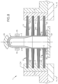
- the preforms 2 are oriented neck down (and where they can optionally be devoid of a collar, although in the example illustrated on the figure 8 ).
- the support 29 is for example in the form of a plate on which the preforms 2 rest by their rim 7.
- the brushes 19 extend above the plate 29 and rub could be presented in the form of a pair of rails on which the preforms 2 would rest by their collar (when they are provided with one).
- the conveyor 1 may comprise a bottom guide 34 which extends directly above the plate 29, at a distance therefrom greater than or equal to an overall height of the preforms 2.
- This guide 34 limits the risk of the preforms 2 tilting forward under the effect of the friction forces induced by the brushes 2.
- This guide 34 may be mobile to accompany the preforms along their path and thus further limit the risk of tilting.
- the guide 34 may be in the form of an endless circulating belt mounted between two pulleys.
- slides 35 may be provided, positioned on either side of the body 4 and/or the neck 5.
- the (or each) belt 11 may comprise brushes 19 over its entire length.
- the brushes 19 may be installed vertically or, alternatively, obliquely (i.e. the different tufts may be installed in a staggered manner).
- the conveyor 1 may be equipped with tensioning rollers 36 to put the (or each) belt 11 under tension and thus avoid undulations in the strand 24 running along the path T and maintain a constant orientation of the bristles 21 there, for the benefit of the efficiency of the drive of the preforms 2.
- Each tensioning roller 36 is for example mounted on a plate 37 fixed in an adjustable manner transversely on the plate 15 of the conveyor 1.
- the brushes 19 could be mounted on several independent superimposed belts, which would circulate for example at different speeds so as to maintain permanent friction of the brushes 19 with the side wall 3 of the preforms.
- conveyor 1 can be equipped, as shown in the figure 1 , of one or more device(s) 38 for cleaning (or decontaminating) the brushes 19, operating for example by suction, by exposure to ultraviolet rays or to ionized air. This results in decontamination of conveyor 1 (and therefore of preforms 2), and its compliance with current health standards.
- the conveyor 1 may be equipped with at least one preform ejector, making it possible to extract from the flow of preforms circulating in the conveyor 1 any preform that is poorly oriented and risks causing a blockage or intermingling of the preforms 2 along the path, likely to damage or break at least one of the components of the conveyor 1.
- This ejector would be in the form, for example, of a mobile section of the support 29, which would form a retractable trapdoor controlled by the detection of one or more poorly oriented preform(s).
Landscapes
- Engineering & Computer Science (AREA)
- Mechanical Engineering (AREA)
- Physics & Mathematics (AREA)
- Fluid Mechanics (AREA)
- Blow-Moulding Or Thermoforming Of Plastics Or The Like (AREA)
- Processing And Handling Of Plastics And Other Materials For Molding In General (AREA)
Claims (15)
- Vorrichtung (1) zum Transport von Kunststoffbehältervorformlingen (2) der Art von Vorformlingen, die dazu bestimmt sind, durch Blasen oder Streckblasformen zu Behältern geformt zu werden, wobei die Vorformlinge aus Kunststoff sind und jeweils eine rohrförmige Wand (3) aufweisen, die einen Körper (4) und einen Hals (5) definiert, die durch einen Kragen (8) getrennt sind, der radial von der Wand (3) vorsteht, wobei die Vorrichtung (1) ein endlos umlaufendes Element (11) umfasst, das eine Außenseite (17) aufweist und eine Reihe von Bürsten (19) trägt, die sich von der Außenseite (17) vorstehend erstrecken und dazu geeignet sind, mit den Vorformlingen (2) in Kontakt zu kommen, um diese durch Reibung entlang einer Bahn (T) mitzunehmen, wobei die Vorrichtung (1) ein Paar voneinander beabstandeter Schienen (31) umfasst, die gemeinsam zumindest einen Teil der Bahn (T) der Vorformlinge (2) definieren, wobei die Schienen (31) koplanare Auflageflächen (30) zur Aufhängung der mit ihrem Hals nach oben ausgerichteten Vorformlinge (2) an ihrem Kragen (8) aufweisen,wobei der Riemen (11) eine der Außenseite (17) gegenüberliegende Innenseite (16) aufweist, wobei die Vorrichtung (1) außerdem eine Halsführung (32) umfasst, die sich senkrecht zu den Schienen (31) in einem Abstand zu diesen erstreckt, der größer als oder so groß wie eine Höhe des Halses (5) der Vorformlinge (2) ist,wobei die Führung der Vorformlinge durch die Halsführung (32) verhindert, dass sich die Kragen (8) von zwei aufeinanderfolgenden Vorformlingen überlagern, und eine Seitenführung (25), auf denen das umlaufende Element (11) über zumindest einen Teil der Bahn (T) mit der Innenseite aufliegt,dadurch gekennzeichnet, dass die Außenseite (17) des Riemens (11) eine Folge von Zinnen (18) bildet, wobei jede Zinne (18) eine Bürste (19) trägt, und dass ein horizontaler Teil (26) der Führung (25) mit Langlöchern (27) versehen ist, in die Schrauben (28) zur Befestigung der Führung (25) an der Platte (15) eingeführt sind, um die Position der Führung (25) in Querrichtung einzustellen.
- Transportvorrichtung (1) nach Anspruch 1, dadurch gekennzeichnet, dass sich zumindest ein Teil der Bürsten (19) unter den Schienen (31) erstreckt, um mit dem Körper (4) der Vorformlinge (2) in Kontakt zu kommen.
- Transportvorrichtung (1) nach Anspruch 1, dadurch gekennzeichnet, dass sich alle Bürsten (19) unter den Schienen (31) erstrecken.
- Transportvorrichtung (1) nach einem der Ansprüche 1 oder 2, dadurch gekennzeichnet, dass sich ein Teil der Bürsten (19) über den Schienen (31) erstreckt, um am Hals (5) zu reiben.
- Transportvorrichtung (1) nach Anspruch 1 oder 2, dadurch gekennzeichnet, dass die Halsführung (32) die Form einer Stange mit rechteckigem Querschnitt aufweist, die eine ebene Unterseite (33) aufweist, die von einer Trinköffnung (7) der Vorformlinge (2) um einige Zehntelmillimeter beabstandet ist.
- Transportvorrichtung (1) nach einem der Ansprüche 1 bis 5, dadurch gekennzeichnet, dass sie zwei umlaufende Elemente (11) umfasst, die mit Bürsten (19) versehen sind und entlang der Bahn (T) parallele Stränge (24) aufweisen, um die Vorformlinge (2) durch Reibung gemeinsam zu bewegen.
- Transportvorrichtung (1) nach einem der vorangehenden Ansprüche, dadurch gekennzeichnet, dass jede Bürste (19) eine Reihe übereinanderliegender Büschel (20) von Borsten (21) umfasst.
- Transportvorrichtung (1) nach einem der vorangehenden Ansprüche, dadurch gekennzeichnet, dass jedes umlaufende Element (11) über seine gesamte Länge Bürsten (19) umfasst.
- Transportvorrichtung (1) nach einem der vorangehenden Ansprüche, dadurch gekennzeichnet, dass die Anordnung der Bürsten (19) vertikal ist.
- Transportvorrichtung (1) nach einem der Ansprüche 1 bis 8, dadurch gekennzeichnet, dass die Anordnung der Bürsten (19) schräg ist, d. h., dass die einzelnen Büschel versetzt angeordnet sein können.
- Transportvorrichtung (1) nach einem der vorangehenden Ansprüche, dadurch gekennzeichnet, dass die Bürsten (19) auf mehreren übereinanderliegenden Riemen montiert sind.
- Transportvorrichtung (1) nach Anspruch 11, dadurch gekennzeichnet, dass sich die unabhängigen übereinanderliegenden Riemen mit unterschiedlichen Geschwindigkeiten bewegen, sodass eine ständige Reibung der Bürsten (19) an der Seitenwand (3) der Vorformlinge aufrechterhalten wird.
- Transportvorrichtung (1) nach einem der vorangehenden Ansprüche, dadurch gekennzeichnet, dass sie eine oder mehrere Vorrichtung(en) (38) zur Reinigung oder Dekontaminierung der Bürsten (19) umfasst.
- Transportvorrichtung (1) nach Anspruch 13, dadurch gekennzeichnet, dass die Vorrichtung(en) (38) zur Reinigung oder Dekontaminierung durch Absaugen, Bestrahlung mit ultraviolettem Licht oder ionisierter Luft funktioniert (funktionieren).
- Transportvorrichtung (1) nach einem der vorangehenden Ansprüche, dadurch gekennzeichnet, dass sie mindestens einen Vorformauswerfer umfasst.
Applications Claiming Priority (3)
| Application Number | Priority Date | Filing Date | Title |
|---|---|---|---|
| FR1460870A FR3028254B1 (fr) | 2014-11-10 | 2014-11-10 | Procede de transport de preformes de recipients en matiere plastique |
| PCT/FR2015/052978 WO2016075389A1 (fr) | 2014-11-10 | 2015-11-04 | Convoyeur à brosses pour le transport de préformes |
| EP15808703.1A EP3218289B1 (de) | 2014-11-10 | 2015-11-04 | Bürstengliederband zum transport von vorformlingen |
Related Parent Applications (1)
| Application Number | Title | Priority Date | Filing Date |
|---|---|---|---|
| EP15808703.1A Division EP3218289B1 (de) | 2014-11-10 | 2015-11-04 | Bürstengliederband zum transport von vorformlingen |
Publications (3)
| Publication Number | Publication Date |
|---|---|
| EP4234448A2 EP4234448A2 (de) | 2023-08-30 |
| EP4234448A3 EP4234448A3 (de) | 2023-09-20 |
| EP4234448B1 true EP4234448B1 (de) | 2025-01-15 |
Family
ID=52130478
Family Applications (2)
| Application Number | Title | Priority Date | Filing Date |
|---|---|---|---|
| EP23176452.3A Active EP4234448B1 (de) | 2014-11-10 | 2015-11-04 | Bürstengliederband zum transport von vorformlingen |
| EP15808703.1A Active EP3218289B1 (de) | 2014-11-10 | 2015-11-04 | Bürstengliederband zum transport von vorformlingen |
Family Applications After (1)
| Application Number | Title | Priority Date | Filing Date |
|---|---|---|---|
| EP15808703.1A Active EP3218289B1 (de) | 2014-11-10 | 2015-11-04 | Bürstengliederband zum transport von vorformlingen |
Country Status (5)
| Country | Link |
|---|---|
| US (1) | US10035655B2 (de) |
| EP (2) | EP4234448B1 (de) |
| CN (1) | CN107074447B (de) |
| FR (1) | FR3028254B1 (de) |
| WO (1) | WO2016075389A1 (de) |
Families Citing this family (9)
| Publication number | Priority date | Publication date | Assignee | Title |
|---|---|---|---|---|
| FR3051780A1 (fr) | 2016-05-25 | 2017-12-01 | Sidel Participations | Procede de deblocage du defilement de corps creux dans un convoyeur a glissiere |
| FR3057860B1 (fr) * | 2016-10-20 | 2020-10-23 | Sidel Participations | Agencement pour tasser des preformes en file dans un convoyeur |
| FR3093714A1 (fr) | 2019-03-14 | 2020-09-18 | Sidel Participations | "Procédé de démarrage à vide d'un ensemble de distribution de préformes redressées et alignées équipé d'un convoyeur pneumatique" |
| FR3097214A1 (fr) | 2019-06-11 | 2020-12-18 | Sidel Participations | Circuit d'accumulation de préforme comportant au moins deux convoyeurs à brosses agencés en série |
| FR3102761A1 (fr) | 2019-11-05 | 2021-05-07 | Sidel Participations | Circuit d'accumulation de préformes alignées et redressées |
| CN111729876B (zh) * | 2020-08-18 | 2021-04-16 | 新乡职业技术学院 | 一种智能制造用测控机 |
| CN114148672B (zh) * | 2021-12-10 | 2022-12-09 | 广东华工环源环保科技有限公司 | 一种蛋托堆叠后的分离装置 |
| FR3142465A1 (fr) | 2022-11-29 | 2024-05-31 | Sidel Participations | Procede de determination de la force de poussee produite par un convoyeur d’accumulation |
| US20260041226A1 (en) * | 2024-08-07 | 2026-02-12 | Graham Packaging Company, L.P. | Brush systems, transfer systems, and molding systems including same |
Family Cites Families (17)
| Publication number | Priority date | Publication date | Assignee | Title |
|---|---|---|---|---|
| US4026406A (en) * | 1975-07-08 | 1977-05-31 | Barilla G. & R. F.11I S.P.A. | Machine for withdrawing bread slices or like products from a continuous cycle belt-type baking oven, and presenting them in a horizontal stack |
| DE8709053U1 (de) * | 1987-07-01 | 1987-09-10 | Fripack AG, Baar | Vorrichtung zum Gruppieren von Packungen |
| DE4114475A1 (de) * | 1991-05-03 | 1992-11-05 | Khs Verpackungstechnik Gmbh | Vorrichtung zum einweisen von kontinuierlich zulaufenden stueckguetern |
| IT1280736B1 (it) * | 1995-09-15 | 1998-02-06 | Sasib Beverage Medium Speed Sp | Procedimento di trasporto per contenitori, in particolare per conteni- tori in materiale plastico in condizione sospesa, e trasportatore |
| IL118123A0 (en) * | 1996-05-02 | 1996-09-12 | Farkas Shmuel | Conveyor propulsion system |
| FR2767517B1 (fr) * | 1997-08-25 | 2001-03-02 | Netra Systems | Convoyeur pour recipients avec guides permettant de limiter le basculement des recipients par rapport a la verticale dans leur direction de transport |
| AU766223B2 (en) * | 1999-09-16 | 2003-10-09 | Ferag Ag | Method and device for feeding flat items to individualization |
| HRP20020713A2 (en) * | 2001-09-06 | 2003-06-30 | Vt Zurich Marketing Pte Ltd | Conveyor for containers provided with lateral aperture designed for transport |
| DE502006008394D1 (de) * | 2005-09-09 | 2011-01-05 | Sidel Participations Sas | Vorrichtung zum transportieren von gegenständen |
| DE102005043282A1 (de) * | 2005-09-09 | 2007-03-15 | Alpha2Omega Ag | Behältertransportvorrichtung |
| JP5159389B2 (ja) * | 2007-10-10 | 2013-03-06 | サントリーホールディングス株式会社 | 合成樹脂製ボトル搬送装置 |
| DE102009009866A1 (de) * | 2009-02-20 | 2010-08-26 | Krones Ag | Vorrichtung zum Transport von Vorformlingen |
| ITMO20090060A1 (it) * | 2009-03-19 | 2010-09-20 | Sacmi | Metodo e apparato di trasporto |
| FR2956652B1 (fr) | 2010-02-25 | 2015-12-11 | Sidel Participations | Installation de convoyage d'articles en materiau thermoplastique |
| CH704401A1 (de) * | 2011-01-28 | 2012-07-31 | M Tanner Ag | Fördereinrichtung für zylindrische Körper, mit in Förderrichtung geneigten Ablaufschienen. |
| JP5879576B2 (ja) * | 2012-10-26 | 2016-03-08 | キリンテクノシステム株式会社 | 容器搬送装置 |
| GB201220657D0 (en) * | 2012-11-16 | 2013-01-02 | Knight Warner Control Systems Ltd | Movement apparatus for articles |
-
2014
- 2014-11-10 FR FR1460870A patent/FR3028254B1/fr active Active
-
2015
- 2015-11-04 EP EP23176452.3A patent/EP4234448B1/de active Active
- 2015-11-04 CN CN201580060922.4A patent/CN107074447B/zh active Active
- 2015-11-04 EP EP15808703.1A patent/EP3218289B1/de active Active
- 2015-11-04 US US15/525,420 patent/US10035655B2/en active Active
- 2015-11-04 WO PCT/FR2015/052978 patent/WO2016075389A1/fr not_active Ceased
Also Published As
| Publication number | Publication date |
|---|---|
| FR3028254A1 (fr) | 2016-05-13 |
| EP3218289A1 (de) | 2017-09-20 |
| US20170320670A1 (en) | 2017-11-09 |
| US10035655B2 (en) | 2018-07-31 |
| CN107074447A (zh) | 2017-08-18 |
| EP3218289B1 (de) | 2023-06-07 |
| FR3028254B1 (fr) | 2019-04-12 |
| EP4234448A2 (de) | 2023-08-30 |
| EP4234448A3 (de) | 2023-09-20 |
| CN107074447B (zh) | 2019-08-13 |
| WO2016075389A1 (fr) | 2016-05-19 |
Similar Documents
| Publication | Publication Date | Title |
|---|---|---|
| EP4234448B1 (de) | Bürstengliederband zum transport von vorformlingen | |
| CA2969189C (fr) | Dispositif et methode de fourniture d'elements orientes | |
| EP3529181B1 (de) | Anordnung zum zusammenpressen von warteschlangenvorformen in einer fördervorrichtung | |
| EP2771264B1 (de) | Vorrichtung zur übertragung von objekten zwischen maschinen zur intermittierenden bewegung dieser objekte und maschinen zur kontinuierlichen bewegung der objekte sowie entsprechende verpackungsvorrichtung | |
| FR3064989A1 (fr) | Dispositif de convoyeur et procede de convoyage de produits | |
| FR2911587A1 (fr) | DISPOSITIF DE CONVOYAGE D'OBJETS, NOTAMMENT PREFORMES, BOUTEILLES OU ANALOGUES, PAR SOUFFLAGE D'air | |
| EP1327591B1 (de) | Transportvorrichtung für Behälter mit Linearmotor | |
| EP3873719B1 (de) | Verfahren zur verwaltung von in einer heizstation immobilisierten vorformen nach einer produktionsunterbrechung | |
| FR2976196A1 (fr) | Dispositif de convoyage d'objets tels que des fruits ou legumes a zones amont d'individualisation bilaterale | |
| FR2802903A1 (fr) | Redresseur de bouteilles, flacons et autres contenants allonges en vue de leur remplissage | |
| WO2011104484A2 (fr) | Installation de convoyage d'articles en materiau thermoplastique | |
| EP3467179A1 (de) | Umkehrmechanismus | |
| EP3914544B1 (de) | Verfahren und vorrichtung zum fördern von behältern in hängender position | |
| FR2933965A1 (fr) | Bande transporteuse sans fin pour dispositif convoyeur et le dispositif convoyeur equipe | |
| FR2933964A1 (fr) | Convoyeur elevateur, en particulier pour produits en vrac | |
| FR3102761A1 (fr) | Circuit d'accumulation de préformes alignées et redressées | |
| WO2020249416A1 (fr) | Circuit d'accumulation de préforme comportant au moins deux convoyeurs á brosses agencés en série | |
| FR3101622A1 (fr) | Convoyeur à accumulation de préformes présentant un trajet en arc de cercle | |
| FR2941220A1 (fr) | Convoyeur a tapis sans fin, pourvu de griffes escamotables. | |
| FR2729648A1 (fr) | Dispositif de transfert de pieces plates d'un premier convoyeur a un deuxieme convoyeur dispose en aval | |
| EP4626815A1 (de) | Verfahren zur bestimmung der von einem stauförderer erzeugten schubkraft | |
| FR2508423A1 (fr) | Dispositif pour la manipulation de boites, notamment de boites de conserves | |
| FR3044301A1 (fr) | Dispositif et methode de convoyage controle |
Legal Events
| Date | Code | Title | Description |
|---|---|---|---|
| PUAI | Public reference made under article 153(3) epc to a published international application that has entered the european phase |
Free format text: ORIGINAL CODE: 0009012 |
|
| STAA | Information on the status of an ep patent application or granted ep patent |
Free format text: STATUS: THE APPLICATION HAS BEEN PUBLISHED |
|
| PUAL | Search report despatched |
Free format text: ORIGINAL CODE: 0009013 |
|
| AC | Divisional application: reference to earlier application |
Ref document number: 3218289 Country of ref document: EP Kind code of ref document: P |
|
| AK | Designated contracting states |
Kind code of ref document: A2 Designated state(s): AL AT BE BG CH CY CZ DE DK EE ES FI FR GB GR HR HU IE IS IT LI LT LU LV MC MK MT NL NO PL PT RO RS SE SI SK SM TR |
|
| AK | Designated contracting states |
Kind code of ref document: A3 Designated state(s): AL AT BE BG CH CY CZ DE DK EE ES FI FR GB GR HR HU IE IS IT LI LT LU LV MC MK MT NL NO PL PT RO RS SE SI SK SM TR |
|
| RIC1 | Information provided on ipc code assigned before grant |
Ipc: B65G 15/14 20060101AFI20230814BHEP |
|
| STAA | Information on the status of an ep patent application or granted ep patent |
Free format text: STATUS: REQUEST FOR EXAMINATION WAS MADE |
|
| 17P | Request for examination filed |
Effective date: 20240320 |
|
| RBV | Designated contracting states (corrected) |
Designated state(s): AL AT BE BG CH CY CZ DE DK EE ES FI FR GB GR HR HU IE IS IT LI LT LU LV MC MK MT NL NO PL PT RO RS SE SI SK SM TR |
|
| GRAP | Despatch of communication of intention to grant a patent |
Free format text: ORIGINAL CODE: EPIDOSNIGR1 |
|
| STAA | Information on the status of an ep patent application or granted ep patent |
Free format text: STATUS: GRANT OF PATENT IS INTENDED |
|
| INTG | Intention to grant announced |
Effective date: 20241021 |
|
| GRAS | Grant fee paid |
Free format text: ORIGINAL CODE: EPIDOSNIGR3 |
|
| GRAA | (expected) grant |
Free format text: ORIGINAL CODE: 0009210 |
|
| STAA | Information on the status of an ep patent application or granted ep patent |
Free format text: STATUS: THE PATENT HAS BEEN GRANTED |
|
| AC | Divisional application: reference to earlier application |
Ref document number: 3218289 Country of ref document: EP Kind code of ref document: P |
|
| AK | Designated contracting states |
Kind code of ref document: B1 Designated state(s): AL AT BE BG CH CY CZ DE DK EE ES FI FR GB GR HR HU IE IS IT LI LT LU LV MC MK MT NL NO PL PT RO RS SE SI SK SM TR |
|
| REG | Reference to a national code |
Ref country code: CH Ref legal event code: EP Ref country code: GB Ref legal event code: FG4D Free format text: NOT ENGLISH |
|
| REG | Reference to a national code |
Ref country code: DE Ref legal event code: R096 Ref document number: 602015090884 Country of ref document: DE |
|
| P01 | Opt-out of the competence of the unified patent court (upc) registered |
Free format text: CASE NUMBER: APP_67973/2024 Effective date: 20241224 |
|
| REG | Reference to a national code |
Ref country code: IE Ref legal event code: FG4D Free format text: LANGUAGE OF EP DOCUMENT: FRENCH |
|
| REG | Reference to a national code |
Ref country code: NL Ref legal event code: MP Effective date: 20250115 |
|
| PG25 | Lapsed in a contracting state [announced via postgrant information from national office to epo] |
Ref country code: NL Free format text: LAPSE BECAUSE OF FAILURE TO SUBMIT A TRANSLATION OF THE DESCRIPTION OR TO PAY THE FEE WITHIN THE PRESCRIBED TIME-LIMIT Effective date: 20250115 |
|
| PG25 | Lapsed in a contracting state [announced via postgrant information from national office to epo] |
Ref country code: RS Free format text: LAPSE BECAUSE OF FAILURE TO SUBMIT A TRANSLATION OF THE DESCRIPTION OR TO PAY THE FEE WITHIN THE PRESCRIBED TIME-LIMIT Effective date: 20250415 |
|
| PG25 | Lapsed in a contracting state [announced via postgrant information from national office to epo] |
Ref country code: FI Free format text: LAPSE BECAUSE OF FAILURE TO SUBMIT A TRANSLATION OF THE DESCRIPTION OR TO PAY THE FEE WITHIN THE PRESCRIBED TIME-LIMIT Effective date: 20250115 |
|
| PG25 | Lapsed in a contracting state [announced via postgrant information from national office to epo] |
Ref country code: PL Free format text: LAPSE BECAUSE OF FAILURE TO SUBMIT A TRANSLATION OF THE DESCRIPTION OR TO PAY THE FEE WITHIN THE PRESCRIBED TIME-LIMIT Effective date: 20250115 |
|
| PG25 | Lapsed in a contracting state [announced via postgrant information from national office to epo] |
Ref country code: ES Free format text: LAPSE BECAUSE OF FAILURE TO SUBMIT A TRANSLATION OF THE DESCRIPTION OR TO PAY THE FEE WITHIN THE PRESCRIBED TIME-LIMIT Effective date: 20250115 |
|
| REG | Reference to a national code |
Ref country code: LT Ref legal event code: MG9D |
|
| PG25 | Lapsed in a contracting state [announced via postgrant information from national office to epo] |
Ref country code: NO Free format text: LAPSE BECAUSE OF FAILURE TO SUBMIT A TRANSLATION OF THE DESCRIPTION OR TO PAY THE FEE WITHIN THE PRESCRIBED TIME-LIMIT Effective date: 20250415 Ref country code: IS Free format text: LAPSE BECAUSE OF FAILURE TO SUBMIT A TRANSLATION OF THE DESCRIPTION OR TO PAY THE FEE WITHIN THE PRESCRIBED TIME-LIMIT Effective date: 20250515 |
|
| REG | Reference to a national code |
Ref country code: AT Ref legal event code: MK05 Ref document number: 1759758 Country of ref document: AT Kind code of ref document: T Effective date: 20250115 |
|
| PG25 | Lapsed in a contracting state [announced via postgrant information from national office to epo] |
Ref country code: HR Free format text: LAPSE BECAUSE OF FAILURE TO SUBMIT A TRANSLATION OF THE DESCRIPTION OR TO PAY THE FEE WITHIN THE PRESCRIBED TIME-LIMIT Effective date: 20250115 |
|
| PG25 | Lapsed in a contracting state [announced via postgrant information from national office to epo] |
Ref country code: PT Free format text: LAPSE BECAUSE OF FAILURE TO SUBMIT A TRANSLATION OF THE DESCRIPTION OR TO PAY THE FEE WITHIN THE PRESCRIBED TIME-LIMIT Effective date: 20250515 Ref country code: LV Free format text: LAPSE BECAUSE OF FAILURE TO SUBMIT A TRANSLATION OF THE DESCRIPTION OR TO PAY THE FEE WITHIN THE PRESCRIBED TIME-LIMIT Effective date: 20250115 |
|
| PG25 | Lapsed in a contracting state [announced via postgrant information from national office to epo] |
Ref country code: GR Free format text: LAPSE BECAUSE OF FAILURE TO SUBMIT A TRANSLATION OF THE DESCRIPTION OR TO PAY THE FEE WITHIN THE PRESCRIBED TIME-LIMIT Effective date: 20250416 Ref country code: BG Free format text: LAPSE BECAUSE OF FAILURE TO SUBMIT A TRANSLATION OF THE DESCRIPTION OR TO PAY THE FEE WITHIN THE PRESCRIBED TIME-LIMIT Effective date: 20250115 |
|
| PG25 | Lapsed in a contracting state [announced via postgrant information from national office to epo] |
Ref country code: AT Free format text: LAPSE BECAUSE OF FAILURE TO SUBMIT A TRANSLATION OF THE DESCRIPTION OR TO PAY THE FEE WITHIN THE PRESCRIBED TIME-LIMIT Effective date: 20250115 |
|
| PG25 | Lapsed in a contracting state [announced via postgrant information from national office to epo] |
Ref country code: SE Free format text: LAPSE BECAUSE OF FAILURE TO SUBMIT A TRANSLATION OF THE DESCRIPTION OR TO PAY THE FEE WITHIN THE PRESCRIBED TIME-LIMIT Effective date: 20250115 |
|
| PG25 | Lapsed in a contracting state [announced via postgrant information from national office to epo] |
Ref country code: SM Free format text: LAPSE BECAUSE OF FAILURE TO SUBMIT A TRANSLATION OF THE DESCRIPTION OR TO PAY THE FEE WITHIN THE PRESCRIBED TIME-LIMIT Effective date: 20250115 |
|
| PG25 | Lapsed in a contracting state [announced via postgrant information from national office to epo] |
Ref country code: DK Free format text: LAPSE BECAUSE OF FAILURE TO SUBMIT A TRANSLATION OF THE DESCRIPTION OR TO PAY THE FEE WITHIN THE PRESCRIBED TIME-LIMIT Effective date: 20250115 |
|
| REG | Reference to a national code |
Ref country code: DE Ref legal event code: R097 Ref document number: 602015090884 Country of ref document: DE |
|
| PG25 | Lapsed in a contracting state [announced via postgrant information from national office to epo] |
Ref country code: EE Free format text: LAPSE BECAUSE OF FAILURE TO SUBMIT A TRANSLATION OF THE DESCRIPTION OR TO PAY THE FEE WITHIN THE PRESCRIBED TIME-LIMIT Effective date: 20250115 Ref country code: CZ Free format text: LAPSE BECAUSE OF FAILURE TO SUBMIT A TRANSLATION OF THE DESCRIPTION OR TO PAY THE FEE WITHIN THE PRESCRIBED TIME-LIMIT Effective date: 20250115 |
|
| PG25 | Lapsed in a contracting state [announced via postgrant information from national office to epo] |
Ref country code: RO Free format text: LAPSE BECAUSE OF FAILURE TO SUBMIT A TRANSLATION OF THE DESCRIPTION OR TO PAY THE FEE WITHIN THE PRESCRIBED TIME-LIMIT Effective date: 20250115 |
|
| PG25 | Lapsed in a contracting state [announced via postgrant information from national office to epo] |
Ref country code: SK Free format text: LAPSE BECAUSE OF FAILURE TO SUBMIT A TRANSLATION OF THE DESCRIPTION OR TO PAY THE FEE WITHIN THE PRESCRIBED TIME-LIMIT Effective date: 20250115 |
|
| PLBE | No opposition filed within time limit |
Free format text: ORIGINAL CODE: 0009261 |
|
| STAA | Information on the status of an ep patent application or granted ep patent |
Free format text: STATUS: NO OPPOSITION FILED WITHIN TIME LIMIT |
|
| 26N | No opposition filed |
Effective date: 20251016 |
|
| PGFP | Annual fee paid to national office [announced via postgrant information from national office to epo] |
Ref country code: DE Payment date: 20251022 Year of fee payment: 11 |
|
| PGFP | Annual fee paid to national office [announced via postgrant information from national office to epo] |
Ref country code: IT Payment date: 20251022 Year of fee payment: 11 |
|
| PGFP | Annual fee paid to national office [announced via postgrant information from national office to epo] |
Ref country code: FR Payment date: 20251023 Year of fee payment: 11 |