EP4234430A2 - Closure assembly for a container and container having a closure assembly - Google Patents
Closure assembly for a container and container having a closure assembly Download PDFInfo
- Publication number
- EP4234430A2 EP4234430A2 EP23170960.1A EP23170960A EP4234430A2 EP 4234430 A2 EP4234430 A2 EP 4234430A2 EP 23170960 A EP23170960 A EP 23170960A EP 4234430 A2 EP4234430 A2 EP 4234430A2
- Authority
- EP
- European Patent Office
- Prior art keywords
- closure assembly
- ring member
- lid
- collar
- container
- Prior art date
- Legal status (The legal status is an assumption and is not a legal conclusion. Google has not performed a legal analysis and makes no representation as to the accuracy of the status listed.)
- Pending
Links
- 230000008878 coupling Effects 0.000 claims abstract description 88
- 238000010168 coupling process Methods 0.000 claims abstract description 88
- 238000005859 coupling reaction Methods 0.000 claims abstract description 88
- 230000003993 interaction Effects 0.000 claims description 55
- 238000005520 cutting process Methods 0.000 claims description 23
- 238000000926 separation method Methods 0.000 claims description 17
- 239000012528 membrane Substances 0.000 claims description 16
- 239000005022 packaging material Substances 0.000 claims description 12
- 230000002441 reversible effect Effects 0.000 claims description 7
- 230000007246 mechanism Effects 0.000 claims description 4
- 238000007789 sealing Methods 0.000 claims description 4
- 235000013305 food Nutrition 0.000 description 9
- 239000000463 material Substances 0.000 description 8
- 239000002657 fibrous material Substances 0.000 description 5
- 230000008901 benefit Effects 0.000 description 4
- 239000004033 plastic Substances 0.000 description 4
- 229920003023 plastic Polymers 0.000 description 4
- 235000013336 milk Nutrition 0.000 description 3
- 239000008267 milk Substances 0.000 description 3
- 210000004080 milk Anatomy 0.000 description 3
- 241000227653 Lycopersicon Species 0.000 description 2
- 235000007688 Lycopersicon esculentum Nutrition 0.000 description 2
- XAGFODPZIPBFFR-UHFFFAOYSA-N aluminium Chemical compound [Al] XAGFODPZIPBFFR-UHFFFAOYSA-N 0.000 description 2
- 229910052782 aluminium Inorganic materials 0.000 description 2
- 230000000712 assembly Effects 0.000 description 2
- 238000000429 assembly Methods 0.000 description 2
- 239000004715 ethylene vinyl alcohol Substances 0.000 description 2
- 239000011888 foil Substances 0.000 description 2
- 235000015203 fruit juice Nutrition 0.000 description 2
- 230000002427 irreversible effect Effects 0.000 description 2
- 235000015067 sauces Nutrition 0.000 description 2
- 235000014101 wine Nutrition 0.000 description 2
- 239000004698 Polyethylene Substances 0.000 description 1
- 230000004913 activation Effects 0.000 description 1
- 238000004026 adhesive bonding Methods 0.000 description 1
- 230000015572 biosynthetic process Effects 0.000 description 1
- 239000011111 cardboard Substances 0.000 description 1
- 230000001419 dependent effect Effects 0.000 description 1
- 239000012530 fluid Substances 0.000 description 1
- 239000007788 liquid Substances 0.000 description 1
- 238000004519 manufacturing process Methods 0.000 description 1
- 239000007769 metal material Substances 0.000 description 1
- 238000000034 method Methods 0.000 description 1
- 230000004048 modification Effects 0.000 description 1
- 238000012986 modification Methods 0.000 description 1
- 238000000465 moulding Methods 0.000 description 1
- 238000004806 packaging method and process Methods 0.000 description 1
- 239000011087 paperboard Substances 0.000 description 1
- -1 polyethylene Polymers 0.000 description 1
- 229920000573 polyethylene Polymers 0.000 description 1
- 230000008569 process Effects 0.000 description 1
- 150000003839 salts Chemical class 0.000 description 1
Images


Classifications
-
- B—PERFORMING OPERATIONS; TRANSPORTING
- B65—CONVEYING; PACKING; STORING; HANDLING THIN OR FILAMENTARY MATERIAL
- B65D—CONTAINERS FOR STORAGE OR TRANSPORT OF ARTICLES OR MATERIALS, e.g. BAGS, BARRELS, BOTTLES, BOXES, CANS, CARTONS, CRATES, DRUMS, JARS, TANKS, HOPPERS, FORWARDING CONTAINERS; ACCESSORIES, CLOSURES, OR FITTINGS THEREFOR; PACKAGING ELEMENTS; PACKAGES
- B65D41/00—Caps, e.g. crown caps or crown seals, i.e. members having parts arranged for engagement with the external periphery of a neck or wall defining a pouring opening or discharge aperture; Protective cap-like covers for closure members, e.g. decorative covers of metal foil or paper
- B65D41/32—Caps or cap-like covers with lines of weakness, tearing-strips, tags, or like opening or removal devices, e.g. to facilitate formation of pouring openings
- B65D41/34—Threaded or like caps or cap-like covers provided with tamper elements formed in, or attached to, the closure skirt
- B65D41/3442—Threaded or like caps or cap-like covers provided with tamper elements formed in, or attached to, the closure skirt with rigid bead or projections formed on the tamper element and coacting with bead or projections on the container
- B65D41/3447—Threaded or like caps or cap-like covers provided with tamper elements formed in, or attached to, the closure skirt with rigid bead or projections formed on the tamper element and coacting with bead or projections on the container the tamper element being integrally connected to the closure by means of bridges
-
- B—PERFORMING OPERATIONS; TRANSPORTING
- B65—CONVEYING; PACKING; STORING; HANDLING THIN OR FILAMENTARY MATERIAL
- B65D—CONTAINERS FOR STORAGE OR TRANSPORT OF ARTICLES OR MATERIALS, e.g. BAGS, BARRELS, BOTTLES, BOXES, CANS, CARTONS, CRATES, DRUMS, JARS, TANKS, HOPPERS, FORWARDING CONTAINERS; ACCESSORIES, CLOSURES, OR FITTINGS THEREFOR; PACKAGING ELEMENTS; PACKAGES
- B65D41/00—Caps, e.g. crown caps or crown seals, i.e. members having parts arranged for engagement with the external periphery of a neck or wall defining a pouring opening or discharge aperture; Protective cap-like covers for closure members, e.g. decorative covers of metal foil or paper
- B65D41/32—Caps or cap-like covers with lines of weakness, tearing-strips, tags, or like opening or removal devices, e.g. to facilitate formation of pouring openings
- B65D41/34—Threaded or like caps or cap-like covers provided with tamper elements formed in, or attached to, the closure skirt
-
- B—PERFORMING OPERATIONS; TRANSPORTING
- B65—CONVEYING; PACKING; STORING; HANDLING THIN OR FILAMENTARY MATERIAL
- B65D—CONTAINERS FOR STORAGE OR TRANSPORT OF ARTICLES OR MATERIALS, e.g. BAGS, BARRELS, BOTTLES, BOXES, CANS, CARTONS, CRATES, DRUMS, JARS, TANKS, HOPPERS, FORWARDING CONTAINERS; ACCESSORIES, CLOSURES, OR FITTINGS THEREFOR; PACKAGING ELEMENTS; PACKAGES
- B65D5/00—Rigid or semi-rigid containers of polygonal cross-section, e.g. boxes, cartons or trays, formed by folding or erecting one or more blanks made of paper
- B65D5/42—Details of containers or of foldable or erectable container blanks
- B65D5/72—Contents-dispensing means
- B65D5/74—Spouts
- B65D5/746—Spouts formed separately from the container
- B65D5/747—Spouts formed separately from the container with means for piercing or cutting the container wall or a membrane connected to said wall
- B65D5/748—Spouts formed separately from the container with means for piercing or cutting the container wall or a membrane connected to said wall a major part of the container wall or membrane being left inside the container after the opening
-
- B—PERFORMING OPERATIONS; TRANSPORTING
- B65—CONVEYING; PACKING; STORING; HANDLING THIN OR FILAMENTARY MATERIAL
- B65D—CONTAINERS FOR STORAGE OR TRANSPORT OF ARTICLES OR MATERIALS, e.g. BAGS, BARRELS, BOTTLES, BOXES, CANS, CARTONS, CRATES, DRUMS, JARS, TANKS, HOPPERS, FORWARDING CONTAINERS; ACCESSORIES, CLOSURES, OR FITTINGS THEREFOR; PACKAGING ELEMENTS; PACKAGES
- B65D55/00—Accessories for container closures not otherwise provided for
- B65D55/02—Locking devices; Means for discouraging or indicating unauthorised opening or removal of closure
- B65D55/06—Deformable or tearable wires, strings, or strips; Use of seals, e.g. destructible locking pins
- B65D55/08—Annular elements encircling container necks
- B65D55/0818—Destructible or permanently removable bands, e.g. adhesive
-
- B—PERFORMING OPERATIONS; TRANSPORTING
- B65—CONVEYING; PACKING; STORING; HANDLING THIN OR FILAMENTARY MATERIAL
- B65D—CONTAINERS FOR STORAGE OR TRANSPORT OF ARTICLES OR MATERIALS, e.g. BAGS, BARRELS, BOTTLES, BOXES, CANS, CARTONS, CRATES, DRUMS, JARS, TANKS, HOPPERS, FORWARDING CONTAINERS; ACCESSORIES, CLOSURES, OR FITTINGS THEREFOR; PACKAGING ELEMENTS; PACKAGES
- B65D55/00—Accessories for container closures not otherwise provided for
- B65D55/16—Devices preventing loss of removable closure members
-
- B—PERFORMING OPERATIONS; TRANSPORTING
- B65—CONVEYING; PACKING; STORING; HANDLING THIN OR FILAMENTARY MATERIAL
- B65D—CONTAINERS FOR STORAGE OR TRANSPORT OF ARTICLES OR MATERIALS, e.g. BAGS, BARRELS, BOTTLES, BOXES, CANS, CARTONS, CRATES, DRUMS, JARS, TANKS, HOPPERS, FORWARDING CONTAINERS; ACCESSORIES, CLOSURES, OR FITTINGS THEREFOR; PACKAGING ELEMENTS; PACKAGES
- B65D85/00—Containers, packaging elements or packages, specially adapted for particular articles or materials
- B65D85/70—Containers, packaging elements or packages, specially adapted for particular articles or materials for materials not otherwise provided for
- B65D85/72—Containers, packaging elements or packages, specially adapted for particular articles or materials for materials not otherwise provided for for edible or potable liquids, semiliquids, or plastic or pasty materials
-
- B—PERFORMING OPERATIONS; TRANSPORTING
- B65—CONVEYING; PACKING; STORING; HANDLING THIN OR FILAMENTARY MATERIAL
- B65D—CONTAINERS FOR STORAGE OR TRANSPORT OF ARTICLES OR MATERIALS, e.g. BAGS, BARRELS, BOTTLES, BOXES, CANS, CARTONS, CRATES, DRUMS, JARS, TANKS, HOPPERS, FORWARDING CONTAINERS; ACCESSORIES, CLOSURES, OR FITTINGS THEREFOR; PACKAGING ELEMENTS; PACKAGES
- B65D2401/00—Tamper-indicating means
- B65D2401/15—Tearable part of the closure
- B65D2401/20—Frangible elements completely enclosed in closure skirt
-
- B—PERFORMING OPERATIONS; TRANSPORTING
- B65—CONVEYING; PACKING; STORING; HANDLING THIN OR FILAMENTARY MATERIAL
- B65D—CONTAINERS FOR STORAGE OR TRANSPORT OF ARTICLES OR MATERIALS, e.g. BAGS, BARRELS, BOTTLES, BOXES, CANS, CARTONS, CRATES, DRUMS, JARS, TANKS, HOPPERS, FORWARDING CONTAINERS; ACCESSORIES, CLOSURES, OR FITTINGS THEREFOR; PACKAGING ELEMENTS; PACKAGES
- B65D2401/00—Tamper-indicating means
- B65D2401/15—Tearable part of the closure
- B65D2401/30—Tamper-ring remaining connected to closure after initial removal
Abstract
Description
- The present invention relates to a closure assembly for a container, in particular a container filled or fillable with a pourable product, even more particular a container filled or fillable with a pourable food product.
- The present invention also relates to a container having a closure assembly.
- As is known, many liquid or pourable food products, such as fruit juice, UHT (ultra-high-temperature treated) milk, wine, tomato sauce, etc., are sold in containers, such as packages made of sterilized packaging material, bottles, cans and the like.
- It is furthermore known that often such containers are provided with a closure assembly being provided with a collar delimiting a pouring outlet allowing the outpouring of the pourable product from the container and a lid configured to selectively open and close the pouring outlet and being connected to the collar when closing the pouring outlet.
- It is further known that the closure assembly typically also comprises a ring member surrounding the collar and, prior to the first removal of the lid, the ring member and the lid are connected to one another by means of coupling bridges, which rupture during the first removal of the lid from the collar. Thus, the lost connection between the ring element and the lid by means of the ruptured coupling bridges provides a tamper-evidence.
- An inconvenience is seen in that the lid is separated from the other portions of the closure assembly and the container when opening the pouring outlet. This means e.g. that a user needs to keep the lid in one hand and the other portions of the closure assembly and the container need to be kept in the other one. Furthermore, such inconvenience may lead to an undesired littering of the lid.
- In order to overcome such inconveniences, it has been proposed to hinge the lid to the ring member or to use a tethering element for connecting the ring member and the lid to one another.
- While these solutions work well with lids that do not require rotation of the lid for loosening and fastening the lid to the collar, the application of such concepts have not led to the desired results with respect to closure assemblies that require the unscrewing and the screwing of the lid for opening and closing the pouring outlet.
- It has also been found that some solutions are such that the lid may disturb a user during the outpouring of the pourable food product.
- Therefore, the need is felt in the sector to provide a closure assembly overcoming at least one of the aforementioned inconveniences.
- In particular, the need is felt to provide a closure assembly, which guarantees that the lid remains coupled to the container with the pouring outlet being open and to provide a reliable tamper-evidence.
- In addition or alternatively, the need is felt to provide a closure assembly, which allows to fasten and loosen the lid to the collar by means of a rotation and to guarantee that the lid remains coupled to the container with the pouring outlet being open and providing for a reliable tamper-evidence.
- It is therefore an object of the present invention to provide in a straightforward and low-cost manner an improved closure assembly for containers, in particular filled or fillable with a pourable product, even more particular filled or fillable with a pourable food product.
- It is another object of the present invention to provide in a straightforward and low-cost manner an improved closure assembly for containers, which guarantees the coupling of various portions of the containers to one another during the steps of their use.
- It is a further object of the present invention to provide in a straightforward and low-cost manner a container, in particular filled or fillable with a pourable product, even more particular filled or fillable with a pourable food product, having a closure assembly.
- According to the present invention, there is provided a closure assembly according to
independent claim 1. - Further advantageous embodiments of the closure assembly are specified in the dependent claims.
- According to the present invention, there is also provided a container according to
claim 14. - A non-limiting embodiment of the present invention will be described by way of example with reference to the accompanying drawings, in which:
-
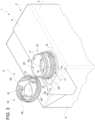
Figure 1 is a schematic perspective view of a container having a closure assembly according to the present invention and the closure assembly being arranged in a first state, with parts removed for clarity; -
Figure 2 is a schematic perspective view of a portion of the container ofFigure 1 with the closure assembly being arranged in a second state, with parts removed for clarity; -
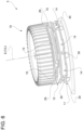
Figure 3 is a schematic perspective view of a portion of the container ofFigure 1 with the closure assembly being arranged in a third state, with parts removed for clarity; -
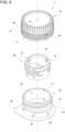
Figure 4 is an exploded view of the closure assembly ofFigures 1 to 3 , with parts removed for clarity; -
Figure 5 is an enlarged perspective view of details of the closure assembly ofFigures 1 to 3 being in the first state, with parts removed for clarity; -
Figure 6 is an enlarged perspective view of details of the closure assembly ofFigures 1 to 3 being in the second state, with parts removed for clarity; -
Figure 7 is an enlarged perspective view of details of the closure assembly ofFigures 1 to 3 being in the third state, with parts removed for clarity; -
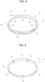
Figure 8 is a perspective view of a portion of the closure assembly ofFigures 1 to 3 , with parts removed for clarity; and -
Figure 9 is a perspective view of another portion of the closure assembly ofFigures 1 to 3 , with parts removed for clarity. -
Number 1 indicates as a whole a container, such as a bottle, a package, a can or the like, comprising amain body 2 and aclosure assembly 3 coupled or coupleable tomain body 2. - Preferably but not necessarily,
container 1 is filled or fillable with a pourable product, in particular a pourable food product, even more particular a sterilized and/or a sterile-processed pourable food product, such as fruit juice, milk (e.g. ultra-high-temperature treated milk), wine, tomato sauce, sugar, salt and others. - The following description will refer to
containers 1, in particularmain bodies 2, obtained from a web of packaging material having a multilayer structure, although this is in no way intended to limit the scope of protection as defined by the accompanying claims. - In particular, the web of packaging material comprises at least a layer of fibrous material, such as e.g. a paper or cardboard layer, and at least two layers of heat-seal plastic material, e.g. polyethylene, interposing the layer of fibrous material in between one another. One of these two layers of heat-seal plastic material defining the inner face of
main body 2 contacting the pourable product. - Preferably but not necessarily, the web of packaging material also comprises a layer of gas- and light-barrier material, e.g. aluminum foil or ethylene vinyl alcohol (EVOH) film, in particular being arranged between one of the layers of the heat-seal plastic material and the layer of fibrous material. Preferentially but not necessarily, the web of packaging material also comprises a further layer of heat-seal plastic material being interposed between the layer of gas- and light-barrier material and the layer of fibrous material.
- According to a preferred non-limiting embodiment,
main body 2 defines a sealed package, in particular a sealed carton package, having a designated pour opening surface area (not shown and known as such), andclosure assembly 3 is fitted tomain body 2 about the designated pour opening surface area. - According to a preferred non-limiting embodiment, closure assembly(ies) 3 is(are) applied to main body(ies) 2 prior, during or after formation, filling and sealing of main body(ies) 2 by means of a molding process and/or adhesive bonding and/or ultrasonic bonding.
- Alternatively, closure assembly(ies) 3 can be applied onto the web of packaging material prior to arranging the web of packaging material within or during advancement of the web of packaging material within a packaging machine for forming, filling and sealing main body(ies) 2 from the web of packaging material.
- With particular reference to
Figure 1 ,main body 2 extends along a longitudinal axis A, a first transversal axis B and a second transversal axis C. In particular, longitudinal axis A is perpendicular to first transversal axis B and second transversal axis C and first transversal axis B and second transversal axis C are perpendicular to one another. - Preferentially but not necessarily, the extension of
main body 2 along longitudinal axis A is larger than the extension ofmain body 2 along first transversal axis B and second transversal axis C. - Preferentially but not necessarily,
main body 2 is parallelepiped-shaped. - According to the non-limiting embodiment disclosed,
main body 2 comprises afirst wall portion 4, in particular being transversal, even more particular perpendicular, to longitudinal axis A, from whichmain body 2 extends along longitudinal axis A. Preferably but not necessarily,first wall portion 4 defines a support surface ofcontainer 1, in particularmain body 2, which, in use, can be put in contact with a support, such as e.g. a shelf, when, in use, being e.g. exposed within a sales point or when being stored. In particular, when being arranged on a support and/or, in use, during consumption of the pourable food product by a consumer fromcontainer 1first wall portion 4 defines a bottom wall portion. - Preferably but not necessarily,
main body 2 also comprises a plurality oflateral walls 5 being (fixedly) connected tofirst wall portion 4 and extending, in particular substantially parallel to longitudinal axis A, fromfirst wall portion 4. - Preferably but not necessarily,
main body 2 also comprises asecond wall portion 6 opposite tofirst wall portion 4 and being (fixedly) connected tolateral walls 5. In other words,lateral walls 5 are interposed betweenfirst wall portion 4 andsecond wall portion 6. In particular, when being arranged on a support and/or, in use, during consumption of the pourable food product by a consumer fromcontainer 1,second wall portion 6 defines a top wall portion. - According to some non-limiting embodiments,
first wall portion 4 andsecond wall portion 6 may be parallel to one another. - According to a non-limiting alternative embodiment not shown,
first wall portion 4 andsecond wall portion 6 could be inclined with respect to one another. - According to some non-limiting embodiments,
second wall portion 6 comprises the designated pour opening surface area. - According to a preferred non-limiting embodiment, the designated pour opening surface area of
main body 2 comprises a pouring hole allowing for the outflow of the pourable product frommain body 2. - According to a preferred non-limiting embodiment, the designated pour opening surface area also comprises a separation membrane sealing the pouring hole. In particular, the separation membrane is configured to retain the pourable product within
main body 2 when being intact and to be at least partially (and non-reversibly) openable and/or rupturable and/or cuttable and/or piercable so as to allow the outflow of the pourable product frommain body 2 through at least a portion of the pouring hole. In particular, the separation membrane is configured to allow the outflow of the pourable product after its loss of integrity and to protect the pourable product from the outer environment prior to its cutting and/or opening and/or rupturing and/or piercing. - Preferentially but not necessarily, the separation membrane comprises a gas- and light-barrier material, e.g. aluminum foil or ethylene vinyl alcohol (EVOH) film.
- According to a preferred non-limiting embodiment, the separation membrane is defined by a portion of the web of packaging material, in particular a portion of the layers of the web of packaging material being different from the layer of fibrous material.
- According to a preferred non-limiting embodiment,
closure assembly 3 comprises and/or is formed from a polymeric material. In alternative,closure assembly 3 could comprise and/or is formed from a metallic material. - With particular reference to
Figures 1 to 9 ,closure assembly 3 comprises at least: - a
lid 10; - a
first ring member 11; - a
second ring member 12, in particular coaxial tofirst ring member 11; and - a
coupling element 13 connected tolid 10 and to one offirst ring member 11 andsecond ring member 12, in the specific case shown couplingelement 13 is connected tolid 10 andsecond ring member 12. - Advantageously,
closure assembly 3 also comprises: - one or more rupturable first coupling bridges 14 connecting
first ring member 11 andsecond ring member 12 with one another; and - one or more rupturable second coupling bridges 15 connecting
second ring member 12 andlid 10 with one another. - It should be noted that
coupling element 13 is connected tolid 10 andfirst ring member 11 orsecond ring member 12 in a non-rupturable manner and/or separation resistant manner. This means that upon a normal use ofclosure assembly 3coupling element 13 remains connected tolid 10 andfirst ring member 11 orsecond ring member 12. In particular, the respective connections betweenlid 10 andfirst ring member 11 orsecond ring member 12 are designed to resist an acting force, which exceeds the forces that typically act during a normal use ofclosure assembly 3. An example of the occurrence of such an exceeding acting force is the case when a user intends to willingly detachcoupling element 13 fromlid 10 and/orfirst ring member 11 orsecond ring member 12 by pullinglid 10 andfirst ring member 11 and/orsecond ring member 12 along different directions from one another. - According to a preferred non-limiting embodiment,
coupling element 13 is string-shaped. - In alternative,
coupling element 13 could have any other shape (e.g. being an endless coupling element) and/orclosure assembly 3 comprises more than onecoupling element 13 and/or couplingclement 13 comprises different portions being connected tolid 10 and/orfirst ring member 11 and/orsecond ring member 12. - Advantageously, each
first coupling bridge 14 is arranged in a respective non-ruptured configuration when being connected tofirst ring member 11 andsecond ring member 12 and a respective ruptured configuration when being ruptured (i.e. the respectivefirst coupling bridge 14 is disconnected fromfirst ring member 11 and/orsecond ring member 12. - Advantageously, each
second coupling bridge 15 is arranged in a respective non-ruptured configuration when being connected tosecond ring member 12 andlid 10 and a respective ruptured configuration when being ruptured (i.e. the respectivesecond coupling bridge 15 is disconnected fromsecond ring member 12 and/or lid 10). - In particular, the non-ruptured configuration of each
first coupling bridge 14 and eachsecond coupling bridge 15 is the respective initial configuration (i.e. auser handling container 1 for the first time, finds first coupling bridges and second coupling bridges 15 in their non-ruptured configuration) and the control from the respective non-ruptured configuration to the respective ruptured configuration is irreversible. - In particular, first coupling bridges 14 and second coupling bridges 15 are designed to define at least an initial state of
closure assembly 3 in which first coupling bridges 14 and second coupling bridges 15 are arranged in the respective non-ruptured configuration (i.e. first coupling bridges 14 and second coupling bridges 15 are connected to respectivelyfirst ring member 11 andsecond ring member 12 and tolid 10 and second ring member 12). In particular,closure assembly 3, when being in the initial state is intact (i.e. no manipulation or use ofclosure assembly 3 has been initiated or tried). In other words, the state ofclosure assembly 3 corresponds to the one in whichclosure assembly 3 was applied tomain body 2. - According to a preferred non-limiting embodiment,
closure assembly 3 is arranged in a manipulated state with first coupling bridges 14 and second coupling bridges 15 being arranged in the respective ruptured configurations (i.e.lid 10 is disconnected fromsecond ring member 12 by means of second coupling bridges 15 (while still being connected by means of coupling element 13) andfirst ring member 11 andsecond ring member 12 are disconnected from one another). - According to a preferred non-limiting embodiment, each
first coupling bridge 14 is designed to rupture at a force being equal or larger than a first rupturing force and eachsecond coupling bridge 15 is designed to rupture at a force being equal or larger than a second rupturing force. In particular, the first rupturing force is smaller than the second rupturing force. In this way, it is guaranteed that in use, during a manipulation ofclosure assembly 3, first coupling bridges 14 rupture prior to second coupling bridges 15. - In particular, at least
first ring member 14 acts as a tamper-evidence or in other words,first ring member 14 is designed as a tamper-evidence element. - Preferentially but not necessarily, also
second ring member 15 acts as a tamper-evidence. - Preferentially but not necessarily,
closure assembly 3 is in an intermediate state with first coupling bridges 14 being arranged in the ruptured configuration ad second coupling bridges 15 being arranged in the non-ruptured configuration. - As will be explained further below in more detail, in use, during a first manipulation of
closure assembly 3,closure assembly 3 is at first controlled from the initial state to the intermediate state and then from the intermediate state to the manipulated state. - According to some non-limiting embodiments,
closure assembly 3 also comprises acollar 16 delimiting and/or defining a pouring outlet 17 (of container 1), the pouringoutlet 17 being configured to allow for the outflow of the pourable product fromcontainer 1. - In particular,
first ring member 11 andsecond ring member 12 are coupled to and surroundcollar 16; andlid 10 is connected and/or connectable tocollar 16 and is configured to selectively close and open pouringoutlet 17 for respectively impeding and allowing the outflow of the pourable product fromcontainer 1 through pouringoutlet 17. - According to some non-limiting embodiments,
first ring member 11 andsecond ring member 12 are coaxial tocollar 16. - According to some non-limiting embodiments,
first ring member 11 and/orsecond ring member 12 is/are coupled tocollar 16 in a rotatable manner around respectively a rotation axis E and a rotation axis F, and in particular aroundcollar 16. In particular, rotation axis E and rotation axis F being transversal to first transversal axis B and second transversal axis C. - According to some non-limiting embodiments,
lid 10 andcollar 16 are designed such thatlid 10 can be fastened to and loosened fromcollar 16 by means of rotation (by means of respectively screwing and unscrewing) oflid 10 with respect tocollar 16 around a rotation axis G. In particular, rotation axis G being transversal to first transversal axis B and second transversal axis C. - Preferentially but not necessarily,
lid 10 comprises an inner threadedportion 18, in particular arranged at an inner surface oflid 10, andcollar 16 comprises an outer threadedportion 19, in particular arranged at an outer surface ofcollar 16. Inner threadedportion 18 and outer threadedportion 19 are configured to allow for selectively fastening and looseninglid 10 to and fromcollar 16 by means of a relative rotation betweenlid 10 andcollar 16. - According to some non-limiting embodiments,
closure assembly 3 further comprises acoupling base 20 carryingcollar 16 and being configured to couple and/or connect (seeFigures 4 to 6 ) and/or being coupled and/or connected to (seeFigures 1 to 3 )main body 2. - Preferentially but not necessarily,
coupling base 20 is configured to be fixed and/or is fixed to an outer surface ofmain body 2, in particular ofsecond wall portion 6. In particular,coupling base 20 is arranged in the area of, even more particular at, the designated pour opening surface area. - In particular,
coupling base 20 comprises an opening, in particular a circular opening, andcollar 16 surrounds the opening so that, in use, with the separation membrane being opened and/or cut and/or ruptured and/or pierced a fluid connection between the inside ofmain body 2 and pouringoutlet 17 is established (i.e. the pourable product can flow out of container 1). - Preferentially but not necessarily, at least a portion of coupling base 20 (substantially) has a plate-like configuration.
- Preferentially but not necessarily,
collar 16 extends, in particular from couplingbase 20, along, in particular parallel to, a longitudinal axis I, in particular longitudinal axis I being a central axis ofcollar 16. In particular, the opening ofcoupling base 20,collar 16 and the pouring hole are coaxial to one another. - Preferentially but not necessarily, rotation axis G and longitudinal axis I are parallel, in particular coaxial, to one another.
- According to a preferred non-limiting embodiment,
collar 16 has a circular shape, in particular a circular cross-sectional shape with respect to a sectional plane being orthogonal to longitudinal axis I. - According to some non-limiting embodiments and with particular reference to
Figure 4 ,closure assembly 3 also comprises acutting device 24 configured to rupture and/or pierce and/or cut and/or open the separation membrane and a control device configured to control cuttingdevice 24 from a rest position to an operative position in whichcutting device 24 is adapted to rupture and/or pierce and/or cut and/or open the separation membrane. - Preferentially but not necessarily, cutting
device 24 has an annular shape and is arranged within aninner space 25 ofcollar 16 when being arranged in the rest position and protrudes at least partially out ofinner space 25 when being controlled in the operative position. - In particular, cutting
device 24 is arranged in the rest position withclosure assembly 3 being arranged in the initial state and is arranged in the operative position withclosure assembly 3 being arranged in the manipulated state. - Preferentially but not necessarily, cutting
device 24 is, in use, controlled by means of the control device from the rest configuration to the operative configuration during control ofclosure assembly 3 from the intermediate state to the manipulated state. - Preferentially but not necessarily, cutting
device 24 is in an axially raised position (with respect to longitudinal axis I) when being arranged in the rest position and with respect to the operative position. - According to some non-limiting embodiments, the control device comprises control flaps 26, in particular connected to
lid 10,interaction elements 27 connected to cuttingdevice 24 and a cam mechanism 28 (seeFigure 4 ; known as such and not described in detail) partially associated to cuttingdevice 24 and partially associated tocollar 16. - In particular, control flaps 26 are configured to protrude and/or protrude into
inner space 25. - Preferentially but not necessarily, control flaps 26 are connected to and protrude away from an inner surface portion of
lid 10. - Preferentially but not necessarily, the control device is actuatable through rotation of control flaps 26 around a respective rotation axis, in particular by means of rotation of
lid 10 around rotation axis G. In particular, rotation of control flaps 26 leads, in use, to a rototraslatory movement of cuttingdevice 24, which is guided by means ofcam mechanism 28. - According to some preferred non-limiting embodiments,
lid 10 is controllable in at least a first operative configuration (seeFigures 1 ,2 ,5 and6 ) in whichlid 10 is coaxial tofirst ring member 11 and/orsecond ring member 12 and a second operative configuration (seeFigures 3 and7 ) in whichlid 10 is transversally arranged with respect tofirst ring member 11 and/orsecond ring member 12. - In particular,
lid 10 is configured to close and open pouringoutlet 17 withlid 10 being controlled in respectively the first operative configuration and the second operative configuration. - Preferentially but not necessarily,
lid 10 is controlled in the first operative configuration and the second operative configuration withlid 10 itself being respectively connected to and detached fromcollar 16. In particular,lid 10 is coaxial tocollar 16 when being controlled in the first operative configuration and preferentially but not necessarily is transversal tocollar 16 when being controlled in the second operative configuration. In other words, whenlid 10 is arranged in the firstoperative configuration lid 10 is connected tocollar 16 andcovers pouring outlet 17 and whenlid 10 is arranged in the secondoperative configuration lid 10 is detached fromcollar 16 and clears pouringoutlet 17. - In particular, a
ring portion 29 oflid 10 is parallel to and transversal to ringmember 11 when being controlled in respectively the first operative configuration and the second operative configuration. This latter reflects the fact thatlid 10 needs to be distanced and/or separated fromfirst ring member 11 and/orsecond ring member 12 for allowing the outflow of the pourable product through pouring outlet 17 (see e.g.Figures 3 and7 ). - Preferentially but not necessarily,
coupling element 13 is connected to ringportion 29. - Preferentially but not necessarily,
second ring member 12 is interposed betweenlid 10 andfirst ring member 11 withlid 10 being controlled in the first operative configuration. - In particular,
lid 10 is arranged in the first operative configuration withclosure assembly 3 being controlled in the initial state. - In particular,
closure assembly 3, inparticular lid 10,first ring member 11,second ring member 12, first coupling bridges 14 and second coupling bridges 15 are designed such that thefirst time lid 10 is controlled from the first operative configuration,closure assembly 3 is controlled from the initial state to the manipulated state, in particular from the initial state to the intermediate state and from the intermediate state to the manipulated state. - It should be noted that preferably but not necessarily, while the control of
closure assembly 3 from the initial state to the intermediate state and/or manipulated state is irreversible, the control oflid 10 from the first operative configuration to the second operative configuration is reversible (i.e.lid 10 can be controlled between the first operative configuration and the second operative configuration a plurality of times). - According to some non-limiting embodiments, the control device is configured to move cutting
device 24 from the rest position to the operative position when, in use,closure assembly 3 is in the initial state and during control oflid 10 from the first operative configuration to the second operative configuration. - Preferentially but not necessarily, control flaps 26 protrude into and are removed from
inner space 25 withlid 10 being arranged in respectively the first operative configuration and the second operative configuration. - According to some non-limiting embodiments,
lid 10 is configured to be controlled between the first operative configuration and the second operative configuration by means of a relative rotation oflid 10 around rotation axis G. In particular, inner threadedportion 18 and outer threadedportion 19 are configured to guide the control oflid 10 between the first operative configuration and the second operative configuration. - In particular,
lid 10 is controlled, in use, from the first operative configuration to the second operative configuration and from the second operative configuration to the first operative configuration by rotation oflid 10 around rotation axis G in, respectively, a first sense of rotation and a second sense of rotation opposite to the first sense of rotation. - According to a preferred non-limiting embodiment,
first ring member 11 andsecond ring member 12 are axially displaced (with respect to rotation axis G and/or longitudinal axis I) from one another. - In particular,
first ring member 11 is interposed betweensecond ring member 12 andcoupling base 20. - With particular reference to
Figures 4 ,8 and 9 ,closure assembly 3 further comprises: - a first rupturing device configured to actuate a non-reversible rupturing of first coupling bridges 14 during control of
closure assembly 3 from the initial state to the manipulated state, in particular to the intermediate state and also; and - a second rupturing device configured to actuate a non-reversible rupturing of second coupling bridges 15 during control of
closure assembly 3 from the initial state to the manipulated state, in particular from the initial state to the intermediate state to the manipulated state. - In particular, the first rupturing device and the second rupturing device are activated during control of
lid 10 from the first operative configuration to the second operative configuration, in particular by means of rotation oflid 10 around rotation axis G. - According to a preferred non-limiting embodiment, the first rupturing device and the second rupturing device are configured such that first coupling bridges 14 rupture prior to second coupling bridges 15 during control of
closure assembly 3 from the initial state to the manipulated state. - In particular, the first rupturing device is activated, in use, during control of
closure assembly 3 from the initial state to the intermediate state and the second rupturing device is activated, in use, during control ofclosure assembly 3 from the intermediate state to the manipulated state. - In particular, the first rupturing device is configured to create a force which equals or is larger than the first rupturing force and which is lower than the second rupturing force, while the second rupturing device is configured to create a force, which equals or is larger than the second rupturing force.
- With particular reference to
Figures 4 and9 , the first rupturing device comprises one or morefirst interaction elements 30 associated to and/or carried bycollar 16 and one or moresecond interaction elements 31 associated to and/or carried byfirst ring member 11. In particular, eachsecond interaction element 31 is configured to abut against one respectivefirst interaction element 30 for actuating the non-reversible rupturing of first coupling bridges 14. Even more particular, eachsecond interaction element 31 and the respectivefirst interaction element 30 are designed such that thesecond interaction element 31 abuts, in use, against the respectivefirst interaction element 30 upon a relative rotation of first ring member 11 (around rotation axis E and) with respect tocollar 16. - Preferentially but not necessarily, each
second interaction element 31 and the respectivefirst interaction element 30 are arranged such that eachsecond interaction element 31 abuts, in use, against the respectivefirst interaction element 30 within a relative angular movement offirst ring member 11 with respect tofirst interaction elements 30 of at most 20°. - Preferentially but not necessarily,
first interaction elements 30 are connected to an outer surface ofcollar 26 and radially protrude away fromcollar 26. In particular,first interaction elements 30 are equally spaced around longitudinal axis I. - Preferentially but not necessarily,
second interaction elements 31 are connected to an inner surface offirst ring member 11 facing the outer surface ofcollar 16 and radially protrude away fromfirst ring member 11. In particular,second interaction elements 31 are equally spaced around rotation axis E. - With particular reference to
Figures 4 and8 , the second rupturing device comprises at least onefirst interaction member 32 associated to and/or carried bycollar 16 and one or moresecond interaction members 33 associated to and/or carried bysecond ring member 12. - According to a preferred non-limiting embodiment, each
second interaction member 33 is configured to abut against at least one respective portion offirst interaction member 32 for actuating the non-reversible rupturing of second coupling bridges 15. In particular, eachsecond interaction member 33 and the respectivefirst interaction member 32 are designed such that eachsecond interaction element 33 abuts, in use, against at least a respective portion offirst interaction member 32 upon a relative axial movement ofsecond ring member 12 with respect tofirst interaction member 32 and/orcollar 16. Even more particular, the relative axial movement is actuated by means of rotation oflid 10 around rotation axis G and the interaction between inner threadedportion 18 and outer threadedportion 19. - Preferentially but not necessarily,
second interaction members 33,first interaction member 32 and inner threadedportion 18 and outer threadedportion 19 are arranged such thatsecond interaction members 33 abut, in use, against the respective portions offirst interaction member 32 within a relative angular movement oflid 10 around rotation axis G of at least 20° and of at most 45°. - Preferentially but not necessarily,
first interaction member 32 is connected to the outer surface ofcollar 26 and radially protrudes away fromcollar 26. In particular,first interaction member 32 comprises a ring element connected to and surroundingcollar 16 in a non-rotatable manner. Even more particular, the ring element is integral tocollar 16. - Preferentially but not necessarily,
first interaction member 32 is axially displaced (with respect to longitudinal axis I and) with respect tofirst interaction elements 30. In particular,first interaction elements 30 are interposed betweenfirst interaction member 32 andcoupling base 20. - Preferentially but not necessarily,
second interaction members 33 are connected to an inner surface ofsecond ring member 12 facing the outer surface ofcollar 16 and radially protrude away fromsecond ring member 12. In particular,second interaction members 33 are equally spaced around rotation axis F. - According to the non-limiting embodiment shown,
second interaction members 33 are in the form of flaps protruding from the inner surface ofsecond ring member 12. - According to a preferred non-limiting embodiment,
second ring member 12 comprises arecess 36 for hosting at least a portion ofcoupling element 13 andsecond ring member 12 andlid 10 are axially spaced from another such to host another portion ofcoupling element 13 withclosure assembly 3 being in the first operative configuration. - In use, a user needs to execute a first step of controlling, during which
closure assembly 3 is controlled from the initial state to the manipulated state (prior to a step of outpouring of the pourable product from container 1) . - In particular, during the first step of controlling,
closure assembly 3 is controlled such that first coupling bridges 14 and second coupling bridges 15 rupture, whilelid 10 andsecond ring member 12 remain connected to one another by means ofcoupling element 13. - Even more particular, during the first step of controlling, at
first closure assembly 3 is controlled from the initial state to the intermediate state followed by the control ofclosure assembly 3 from the intermediate state to the manipulated state. - Preferentially but not necessarily, during the control from the initial state to the intermediate state first coupling
bridges 14 rupture disconnectingfirst ring member 11 andsecond ring member 12 from one another and during the control from the intermediate state to the manipulated state second coupling bridges 15 rupture so thatsecond ring member 12 andlid 10 remain connected to one another only by means ofcoupling element 13. - According to a preferred non-limiting embodiment, during the first step of controlling, at first the first rupturing device is activated followed by the activation of the second rupturing device.
- According to a preferred non-limiting embodiment, during the first step of controlling a second step of controlling is executed, during which
lid 10 is controlled from the first operative configuration to the second operative configuration. - Preferentially but not necessarily, during the second step of controlling,
lid 10 is (reversibly) controlled form the first operative configuration to the second operative configuration by means of rotation oflid 10 around rotation axis G and/orcollar 16. - Preferentially but not necessarily, during the first step of controlling and during the second step of controlling, control of
lid 10 from the first operative configuration to the second operative configuration actuates (at first) the first rupturing device and (then) the second rupturing device for rupturing respectively the first coupling bridges 14 and the second coupling bridges 15. - In particular, during the first step of controlling and during the second step of controlling and during the rotation of
lid 10 around rotation axis E bothfirst ring member 11 andsecond ring member 12 rotate around respectively rotation axis E and rotation axis F due the connection oflid 10 andsecond ring member 12 by means ofcoupling element 13 and second coupling bridges 15 and the connection ofsecond ring member 12 andfirst ring member 11 by means of first coupling bridges 14. - According to a preferred non-limiting embodiment, the rotation of
first ring member 11 results in a relative angular movement between eachsecond interaction element 31 and the respectivefirst interaction element 30 until eachsecond interaction element 31 abuts against the respectivefirst interaction element 30, leading to the establishment of the first rupturing force and the rupturing of first coupling bridges 14. This also means that any further rotation oflid 10 is not transferred tofirst ring member 11. - According to a preferred non-limiting embodiment, during the first step of controlling and during the second step of controlling and during the rotation of
lid 10 around rotation axis Esecond ring member 12 is (together with lid 10) also axially displaced, in particular due to the interaction between inner threadedportion 18 and outer threadedportion 19, resulting in a relative axial movement betweensecond interaction members 33 andfirst interaction member 32 until eachsecond interaction member 33 abuts against the respective portion offirst interaction member 32, leading to the establishment of the second rupturing force and the rupturing of second coupling bridges 15. This also means that any further rotation oflid 10 is transferred tosecond ring member 12 by means ofcoupling element 13 only. In particular, during further control steps oflid 10 between the first operative configuration and the second operative configuration,second ring member 12 rotates around rotation axis F. - According to a preferred non-limiting embodiment, during the first step of controlling and/or the second step of controlling, cutting
device 24 is activated for rupturing and/or cutting and/or piercing and/or opening the separation membrane. - The advantages of
closure assembly 3 according to the present invention will be clear from the foregoing description. - In particular,
lid 10 is coupled tocontainer 1 independently on whetherlid 10 is controlled in the first operative configuration or the second operative configuration or any configuration intermediate to both. At the same timefirst ring member 11 clearly allows for a tamper evidence as additionally also the second coupling bridges 15 indicate a tampering. - Another advantage has been identified in that the production of
closure assemblies 3 can be realized relying on molds similar to the one known requiring only minor modifications. - An even other advantage resides in that the gradual control of
closure assembly 3 from the initial state to the intermediate state and from the intermediate state to the manipulated state also allows to understand whether cuttingdevice 24 has already cut and/or opened and/or pierced and/or ruptured the separation membrane. Indeed, cuttingdevice 24 only starts to interact with the separation membrane after the control ofclosure assembly 3 in the intermediate state. Thus, a user understands from the unbroken second coupling bridges 15 that the separation membrane is still intact. - A further advantage resides in that
coupling element 13 allows to control the relative position and the distance betweenlid 10 andsecond ring member 12 in a flexible manner. - Clearly, changes may be made to
container 1 and/orclosure assembly 3 as described herein without, however, departing from the scope of protection as defined in the accompanying claims.
Claims (15)
- - A closure assembly (3) for a container (1) filled or fillable with a pourable product;
the closure assembly (3) comprising:- a lid (10);- a first ring member (11);- a second ring member (12);- a coupling element (13) connected to the lid (10) and to one of the first ring member (11) and the second ring member (12). - Closure assembly (3) according to claim 1, further comprising:- a cutting device (24) configured to rupture and/or pierce and/or cut a separation membrane, and- a control device configured to control the cutting device (24) from a rest position to an operative position in which cutting device (24) is adapted to rupture and/or pierce the separation membrane.
- Closure assembly (3) according to claim 2, further comprising a collar (16) delimiting and/or defining a pouring outlet (17), the pouring outlet (17) being configured to allow for the outflow of the pourable product from the container (1).
- Closure assembly (3) according to claim 3, wherein the first ring member (11) and the second ring member (12) are coupled to and surround the collar (16); and wherein the lid (10) is connected and/or connectable to the collar (16) and is configured to selectively close and open the pouring outlet (17) for respectively impeding and allowing the outflow of the pourable product from the container (1) through the pouring outlet (17).
- Closure assembly (3) according to claim 3 or 4, wherein the lid (10) comprises an inner threaded portion (18), and the collar (16) comprises an outer threaded portion (19), wherein the inner threaded portion (18) and the outer threaded portion (19) are configured to allow for selectively fastening and loosening the lid (10) to and from the collar (16) by means of a relative rotation between the lid (10) and the collar (16).
- Closure assembly (3) according to any one of claims 3 to 5, further comprising a coupling base (20) carrying the collar (16) and being configured to couple and/or to a main body (2) of container (1).
- Closure assembly (3) according to any one of claims 3 to 6, wherein the control device comprises:- control flaps (26),- interaction elements (27) connected to the cutting device (24) and- a cam mechanism (28) partially associated to the cutting device (24) and partially associated to the collar (16),wherein the control device is actuatable through rotation of the control flaps (26) around a respective rotation axis, such that rotation of the control flaps (26) leads, in use, to a rototraslatory movement of cutting device (24), which is guided by means of the cam mechanism (28).
- Closure assembly (3) according to claim 7, wherein the control flaps (26) are connected to the lid (10).
- Closure assembly (3) according to any one of the previous claims, further comprising rupturable first coupling bridges (14) connecting the first ring member (11) and the second ring member (12) to one another.
- Closure assembly (3) according to claim 9, further comprising rupturable second coupling bridges (15) connecting the second ring member (12) and the lid (10) to one another.
- Closure assembly (3) according to claim 10, further comprising a cutting device (24) configured to rupture and/or pierce and/or cut and/or open a separation membrane of the container (1).
- Closure assembly (3) according to claim 10 or 11, wherein the closure assembly (3) is controllable in- an initial state with the first coupling bridge (14) and the second coupling bridge (15) being connected respectively to the first ring member (11) and the second ring member (12) and to the second ring member (12) and the lid (10); and- a manipulated state at which the first coupling bridge (14) and the second coupling bridge (15) are ruptured;wherein the closure assembly (3) further comprises:- a first rupturing device configured to actuate a non-reversible rupturing of the first coupling bridge (14) during control of the closure assembly (3) from the initial state to the manipulated state; and- a second rupturing device configured to actuate a non-reversible rupturing of the second coupling bridge (15) during control of the closure assembly (3) from the initial state to the manipulated state.
- Closure assembly (3) according to claim 12, further comprising a collar (16) delimiting and/or defining a pouring outlet (17), the pouring outlet (17) being configured to allow for the outflow of the pourable product from the container (1),wherein the first rupturing device comprises one or more first interaction elements (30) associated to and/or carried by the collar (16) and one or more second interaction elements (31) associated to and/or carried by first ring member (11),and the second rupturing device comprises at least one first interaction member (32) associated to and/or carried by the collar (16) and one or more second interaction members (33) associated to and/or carried by the second ring member (12) .
- Container (1) comprising a main body (2) and a closure assembly (3) according to any one of the preceding claims and being coupled to the main body (2),
wherein the main body (2) is obtained from a web of packaging material having a multilayer structure. - Container (1) according to claim 14, wherein the main body (2) defines a sealed package, having a designated pour opening surface area, and the closure assembly (3) is fitted to the main body (2) about the designated pour opening surface area,
wherein the designated pour opening surface area of main body (2) comprises: a pouring hole allowing for the outflow of the pourable product from the main body (2), and a separation membrane sealing the pouring hole.
Applications Claiming Priority (2)
| Application Number | Priority Date | Filing Date | Title |
|---|---|---|---|
| EP19200328 | 2019-09-30 | ||
| EP20196227.1A EP3805126B1 (en) | 2019-09-30 | 2020-09-15 | Closure assembly for a container and container having a closure assembly |
Related Parent Applications (1)
| Application Number | Title | Priority Date | Filing Date |
|---|---|---|---|
| EP20196227.1A Division EP3805126B1 (en) | 2019-09-30 | 2020-09-15 | Closure assembly for a container and container having a closure assembly |
Publications (2)
| Publication Number | Publication Date |
|---|---|
| EP4234430A2 true EP4234430A2 (en) | 2023-08-30 |
| EP4234430A3 EP4234430A3 (en) | 2023-10-18 |
Family
ID=68084725
Family Applications (3)
| Application Number | Title | Priority Date | Filing Date |
|---|---|---|---|
| EP23170960.1A Pending EP4234430A3 (en) | 2019-09-30 | 2020-09-15 | Closure assembly for a container and container having a closure assembly |
| EP20196227.1A Active EP3805126B1 (en) | 2019-09-30 | 2020-09-15 | Closure assembly for a container and container having a closure assembly |
| EP22207149.0A Active EP4173987B1 (en) | 2019-09-30 | 2020-09-15 | Closure assembly for a container and container having a closure assembly |
Family Applications After (2)
| Application Number | Title | Priority Date | Filing Date |
|---|---|---|---|
| EP20196227.1A Active EP3805126B1 (en) | 2019-09-30 | 2020-09-15 | Closure assembly for a container and container having a closure assembly |
| EP22207149.0A Active EP4173987B1 (en) | 2019-09-30 | 2020-09-15 | Closure assembly for a container and container having a closure assembly |
Country Status (8)
| Country | Link |
|---|---|
| US (1) | US20220363447A1 (en) |
| EP (3) | EP4234430A3 (en) |
| JP (1) | JP2022550770A (en) |
| CN (2) | CN112572983A (en) |
| BR (1) | BR112022005864A2 (en) |
| ES (1) | ES2951519T3 (en) |
| MX (1) | MX2022002594A (en) |
| WO (1) | WO2021063669A1 (en) |
Cited By (1)
| Publication number | Priority date | Publication date | Assignee | Title |
|---|---|---|---|---|
| EP4166472A1 (en) | 2020-10-05 | 2023-04-19 | Tetra Laval Holdings & Finance S.A. | Container having a closure assembly |
Families Citing this family (7)
| Publication number | Priority date | Publication date | Assignee | Title |
|---|---|---|---|---|
| EP4178868A1 (en) | 2020-07-10 | 2023-05-17 | Rosti Group AB | Multi-component closure |
| DE102021112532A1 (en) | 2021-05-12 | 2022-11-17 | Bericap Holding Gmbh | Web-free, tethered closure device |
| DE202021103289U1 (en) | 2021-06-03 | 2021-07-09 | Sig Technology Ag | Closure for a container with better controlled initial opening and various uses for it |
| EP4098574A1 (en) | 2021-06-03 | 2022-12-07 | SIG Combibloc Services AG | Closure for a container with a controlled initial opening |
| DE102021116173B3 (en) | 2021-06-22 | 2022-03-17 | Bericap Holding Gmbh | bayonet lock |
| DE102021131389B3 (en) | 2021-11-30 | 2022-10-13 | Bericap Holding Gmbh | Closing device with cutting device |
| DE102022110068B3 (en) | 2022-04-26 | 2023-03-02 | Bericap Holding Gmbh | Aseptic closure device |
Citations (4)
| Publication number | Priority date | Publication date | Assignee | Title |
|---|---|---|---|---|
| EP0947433A1 (en) | 1998-04-03 | 1999-10-06 | Tetra Laval Holdings & Finance SA | Device for opening packages of pourable food products |
| US20130043260A1 (en) | 2010-05-04 | 2013-02-21 | Robert Bosch Gmbh | Closure device |
| WO2020109282A1 (en) | 2018-11-26 | 2020-06-04 | Easy Plast S.R.L. | Opening/closing device for a container for pourable products |
| EP3689771A1 (en) | 2019-02-04 | 2020-08-05 | Tetra Laval Holdings & Finance S.A. | Spout for a package and package-spout assembly |
Family Cites Families (11)
| Publication number | Priority date | Publication date | Assignee | Title |
|---|---|---|---|---|
| SI20739A (en) | 2000-11-28 | 2002-06-30 | G.Loc, Trgovina In Storitve D.O.O. | A cap of a container, especially bottle or plastic bottle |
| DE60121920T2 (en) * | 2001-05-29 | 2007-01-18 | Tetra Laval Holdings & Finance S.A. | Lockable opening and pouring device for sealed food containers |
| JP2004307006A (en) * | 2003-04-07 | 2004-11-04 | Toppan Printing Co Ltd | Cap with sealing ring |
| SI1730048T1 (en) | 2004-04-02 | 2008-06-30 | Bormioli Rocco & Figlio Spa | A capsule incorporating a doser and openable security cap, in particular for single-dose flagons |
| JP4908225B2 (en) * | 2004-09-30 | 2012-04-04 | テトラ ラバル ホールディングス アンド ファイナンス エス エイ | Container with cap |
| WO2007058440A1 (en) * | 2005-11-17 | 2007-05-24 | Sang Soo Yi | Ring cap |
| BRPI0816620A2 (en) | 2007-10-10 | 2015-09-15 | Best Easy Cap Co Ltd | "container with a false anti-loss and anti-spin rotation lid" |
| PT2055640E (en) | 2007-11-05 | 2011-04-08 | Tetra Laval Holdings & Finance | Reclosable opening device for packages of pourable food products |
| JP2013517995A (en) | 2010-01-25 | 2013-05-20 | グリーンキャップ カンパニー リミテッド | Cap loss and empty rotation prevention container |
| DE102016110047B3 (en) * | 2016-05-31 | 2017-05-04 | Sig Technology Ag | Pouring element for a composite package and composite packing with a pouring element |
| EP3715271A1 (en) | 2019-03-26 | 2020-09-30 | Tetra Laval Holdings & Finance S.A. | Opening device for a package containing a pourable product |
-
2020
- 2020-09-15 JP JP2022519672A patent/JP2022550770A/en active Pending
- 2020-09-15 EP EP23170960.1A patent/EP4234430A3/en active Pending
- 2020-09-15 MX MX2022002594A patent/MX2022002594A/en unknown
- 2020-09-15 WO PCT/EP2020/075747 patent/WO2021063669A1/en active Application Filing
- 2020-09-15 US US17/640,372 patent/US20220363447A1/en active Pending
- 2020-09-15 BR BR112022005864A patent/BR112022005864A2/en unknown
- 2020-09-15 ES ES20196227T patent/ES2951519T3/en active Active
- 2020-09-15 EP EP20196227.1A patent/EP3805126B1/en active Active
- 2020-09-15 EP EP22207149.0A patent/EP4173987B1/en active Active
- 2020-09-25 CN CN202011025427.9A patent/CN112572983A/en active Pending
- 2020-09-25 CN CN202022136937.5U patent/CN214421197U/en active Active
Patent Citations (4)
| Publication number | Priority date | Publication date | Assignee | Title |
|---|---|---|---|---|
| EP0947433A1 (en) | 1998-04-03 | 1999-10-06 | Tetra Laval Holdings & Finance SA | Device for opening packages of pourable food products |
| US20130043260A1 (en) | 2010-05-04 | 2013-02-21 | Robert Bosch Gmbh | Closure device |
| WO2020109282A1 (en) | 2018-11-26 | 2020-06-04 | Easy Plast S.R.L. | Opening/closing device for a container for pourable products |
| EP3689771A1 (en) | 2019-02-04 | 2020-08-05 | Tetra Laval Holdings & Finance S.A. | Spout for a package and package-spout assembly |
Cited By (1)
| Publication number | Priority date | Publication date | Assignee | Title |
|---|---|---|---|---|
| EP4166472A1 (en) | 2020-10-05 | 2023-04-19 | Tetra Laval Holdings & Finance S.A. | Container having a closure assembly |
Also Published As
| Publication number | Publication date |
|---|---|
| EP3805126A1 (en) | 2021-04-14 |
| JP2022550770A (en) | 2022-12-05 |
| CN112572983A (en) | 2021-03-30 |
| EP4173987A1 (en) | 2023-05-03 |
| US20220363447A1 (en) | 2022-11-17 |
| EP4173987C0 (en) | 2024-01-24 |
| BR112022005864A2 (en) | 2022-06-21 |
| EP3805126B1 (en) | 2023-05-17 |
| MX2022002594A (en) | 2022-03-25 |
| EP4173987B1 (en) | 2024-01-24 |
| WO2021063669A1 (en) | 2021-04-08 |
| EP4234430A3 (en) | 2023-10-18 |
| CN214421197U (en) | 2021-10-19 |
| ES2951519T3 (en) | 2023-10-23 |
Similar Documents
| Publication | Publication Date | Title |
|---|---|---|
| EP3805126B1 (en) | Closure assembly for a container and container having a closure assembly | |
| EP3978387B1 (en) | Closure assembly for a container and container having a closure assembly | |
| EP3715276B1 (en) | Opening device for a packaging for pourable products | |
| EP3798150A1 (en) | Closure assembly for a container and container having a closure assembly | |
| US20230044435A1 (en) | Spout for a container and package-spout assembly | |
| EP3715271A1 (en) | Opening device for a package containing a pourable product | |
| US20230124456A1 (en) | Lid-spout assembly for a package and package having a lid-spout assembly | |
| RU2812027C1 (en) | Closing unit for container and container having closing unit | |
| CN114981178A (en) | Spout for packaging, lid and spout assembly for packaging and package having spout | |
| CN114981176A (en) | Spout for packaging, lid and spout assembly for packaging and package having spout | |
| WO2024088804A1 (en) | Closure assembly for a container and container having a closure assembly | |
| EP4079652B1 (en) | Opening device for a package and package having an opening device | |
| US20230115201A1 (en) | Lid assembly for a container, container having a lid assembly and method of coupling a lid assembly to a spout | |
| EP3915894A1 (en) | Lid-spout assembly for a package and package having a lid-spout assembly | |
| WO2007128775A1 (en) | Pour spout fitment, attached to packaging material |
Legal Events
| Date | Code | Title | Description |
|---|---|---|---|
| PUAI | Public reference made under article 153(3) epc to a published international application that has entered the european phase |
Free format text: ORIGINAL CODE: 0009012 |
|
| STAA | Information on the status of an ep patent application or granted ep patent |
Free format text: STATUS: THE APPLICATION HAS BEEN PUBLISHED |
|
| AC | Divisional application: reference to earlier application |
Ref document number: 3805126 Country of ref document: EP Kind code of ref document: P |
|
| AK | Designated contracting states |
Kind code of ref document: A2 Designated state(s): AL AT BE BG CH CY CZ DE DK EE ES FI FR GB GR HR HU IE IS IT LI LT LU LV MC MK MT NL NO PL PT RO RS SE SI SK SM TR |
|
| REG | Reference to a national code |
Ref country code: DE Ref legal event code: R079 Free format text: PREVIOUS MAIN CLASS: B65D0055160000 Ipc: B65D0041340000 |
|
| PUAL | Search report despatched |
Free format text: ORIGINAL CODE: 0009013 |
|
| AK | Designated contracting states |
Kind code of ref document: A3 Designated state(s): AL AT BE BG CH CY CZ DE DK EE ES FI FR GB GR HR HU IE IS IT LI LT LU LV MC MK MT NL NO PL PT RO RS SE SI SK SM TR |
|
| RIC1 | Information provided on ipc code assigned before grant |
Ipc: B65D 5/74 20060101ALI20230913BHEP Ipc: B65D 55/16 20060101ALI20230913BHEP Ipc: B65D 51/16 20060101ALI20230913BHEP Ipc: B65D 41/34 20060101AFI20230913BHEP |
|
| STAA | Information on the status of an ep patent application or granted ep patent |
Free format text: STATUS: REQUEST FOR EXAMINATION WAS MADE |
|
| TPAC | Observations filed by third parties |
Free format text: ORIGINAL CODE: EPIDOSNTIPA |
|
| 17P | Request for examination filed |
Effective date: 20231218 |
|
| STAA | Information on the status of an ep patent application or granted ep patent |
Free format text: STATUS: EXAMINATION IS IN PROGRESS |
|
| TPAC | Observations filed by third parties |
Free format text: ORIGINAL CODE: EPIDOSNTIPA |
|
| 17Q | First examination report despatched |
Effective date: 20240402 |