EP4079652B1 - Opening device for a package and package having an opening device - Google Patents
Opening device for a package and package having an opening device Download PDFInfo
- Publication number
- EP4079652B1 EP4079652B1 EP22167960.8A EP22167960A EP4079652B1 EP 4079652 B1 EP4079652 B1 EP 4079652B1 EP 22167960 A EP22167960 A EP 22167960A EP 4079652 B1 EP4079652 B1 EP 4079652B1
- Authority
- EP
- European Patent Office
- Prior art keywords
- covering membrane
- opening
- opening device
- weakening line
- base frame
- Prior art date
- Legal status (The legal status is an assumption and is not a legal conclusion. Google has not performed a legal analysis and makes no representation as to the accuracy of the status listed.)
- Active
Links
- 239000012528 membrane Substances 0.000 claims description 94
- 230000003313 weakening effect Effects 0.000 claims description 48
- 238000000926 separation method Methods 0.000 claims description 12
- 230000008878 coupling Effects 0.000 claims description 4
- 238000010168 coupling process Methods 0.000 claims description 4
- 238000005859 coupling reaction Methods 0.000 claims description 4
- 239000005022 packaging material Substances 0.000 description 18
- 239000004033 plastic Substances 0.000 description 12
- 229920003023 plastic Polymers 0.000 description 12
- 235000013305 food Nutrition 0.000 description 11
- 239000000463 material Substances 0.000 description 11
- 238000007789 sealing Methods 0.000 description 5
- 239000002657 fibrous material Substances 0.000 description 4
- XAGFODPZIPBFFR-UHFFFAOYSA-N aluminium Chemical compound [Al] XAGFODPZIPBFFR-UHFFFAOYSA-N 0.000 description 3
- 229910052782 aluminium Inorganic materials 0.000 description 3
- 238000011049 filling Methods 0.000 description 3
- 239000011888 foil Substances 0.000 description 3
- 239000004698 Polyethylene Substances 0.000 description 2
- 239000002131 composite material Substances 0.000 description 2
- 230000007423 decrease Effects 0.000 description 2
- 239000004715 ethylene vinyl alcohol Substances 0.000 description 2
- 235000021056 liquid food Nutrition 0.000 description 2
- 238000004806 packaging method and process Methods 0.000 description 2
- 239000000123 paper Substances 0.000 description 2
- 230000002093 peripheral effect Effects 0.000 description 2
- -1 polyethylene Polymers 0.000 description 2
- 229920000573 polyethylene Polymers 0.000 description 2
- 235000007688 Lycopersicon esculentum Nutrition 0.000 description 1
- 240000003768 Solanum lycopersicum Species 0.000 description 1
- 230000015572 biosynthetic process Effects 0.000 description 1
- 239000011111 cardboard Substances 0.000 description 1
- 239000011091 composite packaging material Substances 0.000 description 1
- 230000001419 dependent effect Effects 0.000 description 1
- 238000005755 formation reaction Methods 0.000 description 1
- 235000015203 fruit juice Nutrition 0.000 description 1
- 239000007788 liquid Substances 0.000 description 1
- 235000013336 milk Nutrition 0.000 description 1
- 239000008267 milk Substances 0.000 description 1
- 210000004080 milk Anatomy 0.000 description 1
- 238000000465 moulding Methods 0.000 description 1
- 239000010813 municipal solid waste Substances 0.000 description 1
- 239000011087 paperboard Substances 0.000 description 1
- 230000000717 retained effect Effects 0.000 description 1
- 235000015067 sauces Nutrition 0.000 description 1
- 235000014101 wine Nutrition 0.000 description 1
Images


Classifications
-
- B—PERFORMING OPERATIONS; TRANSPORTING
- B65—CONVEYING; PACKING; STORING; HANDLING THIN OR FILAMENTARY MATERIAL
- B65D—CONTAINERS FOR STORAGE OR TRANSPORT OF ARTICLES OR MATERIALS, e.g. BAGS, BARRELS, BOTTLES, BOXES, CANS, CARTONS, CRATES, DRUMS, JARS, TANKS, HOPPERS, FORWARDING CONTAINERS; ACCESSORIES, CLOSURES, OR FITTINGS THEREFOR; PACKAGING ELEMENTS; PACKAGES
- B65D5/00—Rigid or semi-rigid containers of polygonal cross-section, e.g. boxes, cartons or trays, formed by folding or erecting one or more blanks made of paper
- B65D5/42—Details of containers or of foldable or erectable container blanks
- B65D5/72—Contents-dispensing means
- B65D5/74—Spouts
- B65D5/746—Spouts formed separately from the container
- B65D5/747—Spouts formed separately from the container with means for piercing or cutting the container wall or a membrane connected to said wall
- B65D5/749—Spouts formed separately from the container with means for piercing or cutting the container wall or a membrane connected to said wall a major part of the container wall or membrane being removed from the container after the opening
Definitions
- the present invention relates to an opening device for a package, in particular a package having a sealed main body, filled with a pourable product, even more particular filled with a pourable food product.
- the present invention also relates to a package, in particular a package having a sealed main body, filled with a pourable product, even more particular filled with a pourable food product, and comprising an opening device.
- liquid or pourable food products such as fruit juice, UHT (ultra-high-temperature treated) milk, wine, tomato sauce, etc.
- packages in particular sealed packages, made of sterilized packaging material.
- a typical example is the parallelepiped-shaped package for pourable food products known as Tetra Brik Aseptic (registered trademark), which is made by sealing and folding a laminated strip packaging material.
- the packaging material has a multilayer structure comprising a carton and/or paper base layer, covered on both sides with layers of heat-seal plastic material, e.g. polyethylene.
- the packaging material also comprises a layer of oxygen-barrier material, e.g. an aluminum foil, which is superimposed on a layer of heat-seal plastic material, and is in turn covered with another layer of heat-seal plastic material forming the inner face of the package eventually contacting the food product.
- Some of the known packages in particular sealed main bodies of the packages formed from the packaging material, comprise a designated pour opening, which allows the outpouring of the pourable product from the packages.
- a known type of opening device comprises a base frame arranged about the designated pour opening and a covering membrane rupturably coupled to the frame so as to cover and seal the designated pour opening prior to the first-time use of the package.
- a covering membrane rupturably coupled to the frame so as to cover and seal the designated pour opening prior to the first-time use of the package.
- JPH0789535A discloses a pouring out port made of a plastic that is attached on the top surface of a paper container main body.
- an opening device according to the independent claim.
- Figures 4 and 5 are bottom views of the package with the opening device being, respectively, in the first configuration and in a third configuration, with parts removed for clarity.
- Number 1 indicates as a whole a package for a pourable product, in particular a pourable food product, even more particular a liquid food product, comprising:
- main body 2 may be obtained from a packaging material, in particular a composite packaging material, having a multilayer structure (not shown and known as such).
- main body 2 may be obtained from a respective blank.
- the packaging material may be provided in the form of a web.
- main body 2 may be obtained by forming a tube from the packaging material, longitudinally sealing the tube, filling the tube with the pourable product and by transversally sealing and cutting the tube.
- the packaging material may comprise at least one layer of fibrous material, such as e.g. a paper or cardboard, and at least two layers of heat-seal plastic material, e.g. polyethylene, interposing the layer of fibrous material in between one another.
- fibrous material such as e.g. a paper or cardboard
- heat-seal plastic material e.g. polyethylene
- the packaging material may also comprise a layer of gas- and light-barrier material, e.g. aluminum foil or ethylene vinyl alcohol (EVOH) film, in particular being arranged between one of the layers of the heat-seal plastic material and the layer of fibrous material.
- the packaging material may also comprise a further layer of heat-seal plastic material being interposed between the layer of gas- and light-barrier material and the layer of fibrous material.
- opening device 4 may be applied onto the packaging material and/or base package 2 prior, during and/or after the formation, filling and sealing of main body 2.
- opening device 4 may be applied onto the packaging material prior to arranging the packaging material within or during advancement of the packaging material through a packaging machine for forming, filling and sealing main bodies 2 from the packaging material.
- opening device 4 may be fused and/or welded and/or bond and/or molded onto main body 2 and/or the packaging material and around the designated pour outlet.
- main body 2 may extend along a longitudinal axis A, a first transversal axis B and a second transversal axis C.
- the extension of package 2 along longitudinal axis A may be larger than the extension of package 2 along first transversal axis B and second transversal axis C.
- main body 2 may be parallelepiped-shaped.
- main body 2 may have a tubular shape or any other shape.
- main body 2 may comprise a first wall portion 5, in particular being transversal, in particular perpendicular, to longitudinal axis A, and from which main body 2 extends along longitudinal axis A.
- first wall portion 5 may define a support surface of package 1, in particular main body 2, which is designed to be put in contact with a support, such as e.g. a shelf, in particular when, in use, being e.g. exposed within a sales point or when being stored.
- a support such as e.g. a shelf
- main body 2 may also comprise one or more lateral walls 6, in the specific case shown four, being (fixedly) connected to first wall portion 5 and extending, in particular substantially parallel to longitudinal axis A, from first wall portion 5.
- main body 2 may also comprise a second wall portion 7 opposite to first wall portion 5 and being (fixedly) connected to at least some of lateral walls 6.
- lateral walls 6 may be interposed between first wall portion 5 and second wall portion 7.
- second wall portion 7 may define a top wall portion.
- first wall portion 5 and second wall portion 7 may be parallel to one another.
- first wall portion 5 and second wall portion 7 may be inclined with respect to one another.
- second wall portion 7 may carry and/or comprise designated pour opening 3.
- package 1, in particular main body 2 may comprise an inner space 8 configured to contain and/or containing the pourable product.
- first wall portion 5, lateral walls 8 and second wall portion 7 delimit inner space 8.
- main body 2 may comprise a separation membrane (not shown and known as such) covering designated pour opening 3.
- the separation membrane may separate in the area of, in particular at, designated pour opening 3 inner space 8 from an outer environment.
- the separation membrane may comprise a gas- and light-barrier material, e.g. aluminum foil or ethylene vinyl alcohol (EVOH) film.
- the separation membrane may be fused together with a portion of opening device 4.
- opening device 4 comprises at least:
- (plastic) weakening line 12 is configured such that, in use, upon exertion of an opening force on covering membrane 11, covering membrane 11 (irreversibly) separates from base frame 10 along weakening line 12. In other words, upon exertion of the opening force weakening line 12 (irreversibly) ruptures so as to separate covering membrane 11 from base frame 10 along weakening line 12.
- covering membrane 11 is designed to cover and seal in cooperation with base frame 10 the designated pour opening.
- weakening line 12 comprises a first end 13 and a second end 14 distinct and separated from one another.
- weakening line 12 does not have an annular configuration and/or a closed-loop configuration.
- first end 13 and second end 14 are not in contact with one another.
- weakening line 12 may be arc-shaped.
- covering membrane 11 is further connected to base frame 10 along an (unrupturable) tethering portion 15 extending between first end 13 and second end 14.
- tethering portion 15 tethers covering membrane 11 to base frame 10 even after separation of covering membrane 11 from base frame 10 along weakening line 12. In this manner, one guarantees that covering membrane 11 remains connected to base frame 10 (and main body 2 and package 1 as a whole) avoiding the possibility of an incorrect disposal of covering membrane 11.
- tethering portion 15 is configured such that, in use, upon exertion of the opening force on covering membrane 11, covering membrane 11 remains attached to base frame 10 along tethering portion 15.
- unrupturable indicates that upon a normal use by a user tethering portion 15 does not rupture.
- the opening force suited to allow for the rupturing of weakening line 12 does not allow to rupture tethering portion 15.
- weakening line 12 together with tethering portion 15 may define an annular shape and while, in use, upon exertion of the opening force the weakening line 12 ruptures, tethering portion 15 remains intact.
- tethering portion 15 may be in contact with first end 13 and second end 14.
- the thickness of weakening line 12 may be smaller than the thickness of tethering portion 15.
- covering membrane 11 upon separation of covering membrane 11 from base frame 10 along weakening line 12, covering membrane 11 is angularly moveable around a hinge axis E defined by tethering portion 15.
- covering membrane 11 is angularly moveable from a closing position (see Figures 2 and 4 ) in which covering membrane 11 covers designated pour opening 3 to an opening position in which covering membrane 11 frees designated pour opening 3.
- covering membrane 11 is in the closing position, with covering membrane 11 being connected to base frame 10 along weakening line 12. Even more particular, covering membrane 11 is in the closing position, with weakening line 12 being intact.
- covering membrane 11 is angularly moveable between the opening position and a re-closing position, in which covering membrane 11 covers designated pour opening 3.
- covering membrane 11 may be configured such that prior to the first-time use (i.e. prior to the rupturing of weakening line 12) covering membrane 11 is positioned in the closing position and is designed to cover designated pouring outlet 3 and to also seal designated pouring outlet 3 in cooperation with base frame 10. Additionally, and with particular reference to Figure 5 , covering membrane 11 may be designed such that once covering membrane 11 is separated from base frame 10 along weakening line 12 (i.e. weakening line 12 is ruptured) covering membrane 11 may be in the re-closing position, in which covering membrane 11 covers designated pouring outlet 3, but does not seal designated pouring outlet 3 anymore.
- covering membrane 11 may be biased into the re-closing position, i.e. in the absence of the application of an external force on covering membrane 11, covering membrane 11 returns back to the re-closing position.
- opening device 4 may comprise a retaining element 16 (see further below for more details) configured to interact with covering membrane 11 so as to retain covering membrane 11 in the opening position, in particular so as to guarantee that covering membrane 11 does not disturb the outpouring of the pourable product from package 1, in particular main body 2.
- covering membrane 11 comprises a first portion 17 and a second portion 18 being rupturably connected to one another along an auxiliary weakening line 19.
- Auxiliary weakening line 19 is configured such that, in use, upon exertion of the opening force, and in particular (substantially) simultaneously to the separation of covering membrane 11 from base frame 10, first portion 17 and second portion 18 separate from one another along auxiliary weakening line 19.
- auxiliary weakening line 19 may extend from second end 14.
- auxiliary weakening line 19 and second end 14 are (integrally) connected to one another.
- auxiliary weakening line 19 may extend from second end 14 towards, in particular to, a center 20 of covering membrane 11.
- auxiliary weakening line 19 may be transversal, in particular perpendicular, to weakening line 12.
- first portion 17 and second portion 18 may be configured to interact with retaining element 16 for retaining covering membrane 11 in the opening position.
- first portion 17 and second portion 18 may be configured to hook up with retaining element 16 for retaining covering membrane 11 in the opening position.
- first portion 17 and second portion 18 may be arrangeable such to interpose and/or clamp at least a portion of retaining element 16 between one another for retaining covering membrane 11 in the opening position.
- covering membrane 11 is (substantially) flush with main body 2, in particular second wall portion 7, in particular when being in the closed position.
- covering membrane 11 may be fused with the separation membrane.
- separation membrane may be considered to be part of covering membrane 11.
- opening device 4 may further comprise an opening element 25 connected to covering membrane 11 and configured to allow for the exertion of the opening force on covering membrane 11.
- opening element 25 may be configured to be operated by a consumer so as to exert the opening force.
- opening element 25 may comprise a pull leg 26, in particular a single pull leg 26, connected to covering membrane 11, in particular to a peripheral portion of covering membrane 11. Additionally, opening element 25 may comprise a gripping element 27, for example a ring, connected to pull leg 26 and being designed to be gripped by the consumer.
- pull leg 26 may be arranged at a peripheral portion of covering membrane 11 being opposed to a portion of covering membrane 11 being integrally connected to tethering portion 15.
- pull leg 26 may transversally, in particular (substantially) perpendicularly, extend from covering membrane 11.
- opening element 25, in particular pull leg 26, may be connected to covering membrane 11 at a connecting point, in particular a single connecting point.
- pull leg 26 may be arranged adjacent to second end 14 and auxiliary weakening line 19.
- opening device 4 may further comprise a collar 28 extending from base frame 10 and having an outlet 29, in particular being aligned, even more particular being coaxial, with respect to designated pouring outlet 3.
- collar 28 being designed to allow for a controlled outpouring of the pourable product from package 1, in particular main body 2.
- collar 28 may define retaining element 16. In this manner, one avoids providing opening device 4 with further components.
- first portion 17 and second portion 18 may be arranged and/or arrangeable so as to contact collar 28 from opposite sides thereof for retaining covering membrane 11 in the opening position.
- base frame 10 covering membrane 11, weakening line 12, tethering portion 15, and in particular collar 28, may be obtained, in particular by molding, as a single piece.
- base frame 10 covering membrane 11, weakening line 12, tethering portion 15, and in particular collar 28, may be molded onto main body 2 and/or onto the packaging material from which main body 2 is formed.
- opening device 4 may also comprise a lid 30 coupled and/or couplable to collar 28 and configured to selectively close and open outlet 29.
- lid 30 is of the screw-lid type.
- lid 30 could be of any other type.
- opening device 4 may also comprise a coupling ring 31 coupled to and arranged around collar 28.
- lid 30 may be tethered to coupling ring 31.
- lid 30 may be at least arrangeable in a closed position, in which lid 30 covers outlet 29, and an open position, in which lid 30 is removed from outlet 29.
- a consumer needs to exert the opening force, in particular by relying on opening element 25, on covering membrane 11 so as to separate covering membrane 11 from base frame 10 along weakening line 12. Moreover, the exertion of the opening force also leads to the separation of first portion 17 and second portion 18 along auxiliary weakening line 19.
- lid 30 prior to being able to manipulate covering membrane 11 the user needs to arrange lid 30 in the open position.
- covering membrane 11 may be retained by retaining element 16, in particular collar 28, in the opening position.
- the consumer can arrange covering membrane 11 in the re-closing position, and in particular also arrange lid 30 in the closed position.
- opening device 4 and/or of package 1 according to the present invention will be clear from the foregoing description.
- first portion 17 and second portion 18, which may be arranged and/or arrangeable so as to contact retaining element 16, in particular collar 28, from opposite sides thereof for maintaining covering membrane 11 in the opening position.
Description
- The present invention relates to an opening device for a package, in particular a package having a sealed main body, filled with a pourable product, even more particular filled with a pourable food product.
- Advantageously, the present invention also relates to a package, in particular a package having a sealed main body, filled with a pourable product, even more particular filled with a pourable food product, and comprising an opening device.
- As is known, many liquid or pourable food products, such as fruit juice, UHT (ultra-high-temperature treated) milk, wine, tomato sauce, etc., are sold in packages, in particular sealed packages, made of sterilized packaging material.
- A typical example is the parallelepiped-shaped package for pourable food products known as Tetra Brik Aseptic (registered trademark), which is made by sealing and folding a laminated strip packaging material. The packaging material has a multilayer structure comprising a carton and/or paper base layer, covered on both sides with layers of heat-seal plastic material, e.g. polyethylene. In the case of aseptic packages for long-storage products, the packaging material also comprises a layer of oxygen-barrier material, e.g. an aluminum foil, which is superimposed on a layer of heat-seal plastic material, and is in turn covered with another layer of heat-seal plastic material forming the inner face of the package eventually contacting the food product.
- Some of the known packages, in particular sealed main bodies of the packages formed from the packaging material, comprise a designated pour opening, which allows the outpouring of the pourable product from the packages.
- It is known to provide for an opening device so as to seal the designated pour opening prior to the first use of the package.
- A known type of opening device comprises a base frame arranged about the designated pour opening and a covering membrane rupturably coupled to the frame so as to cover and seal the designated pour opening prior to the first-time use of the package. In order to allow for the outpouring of the pourable product it is necessary for a user to remove the covering membrane and to throw the covering membrane into a trash bin.
- However, it may occur that a user may dispose of the covering membrane in an incorrect manner.
- Thus, a desire is felt in the sector to provide for an opening device and/or a package having an opening device, which do(es) not come along with such an inconvenience.
-
JPH0789535A - It is therefore an object of the present invention to provide in a straightforward and low-cost manner an improved opening device for a package, in particular a package having a sealed main body, filled with a pourable product, even more particular filled with a pourable food product.
- In particular, it is an object of the present invention to provide in a straightforward and low-cost manner an improved opening device for a package, in particular a packaging having a sealed main body, filled with a pourable product, even more particular filled with a pourable food product, which decreases the risk of an incorrect disposal of the opening device.
- It is a further object of the present invention to provide in a straightforward and low-cost manner an improved package, in particular a package having a sealed main body, filled with a pourable product, even more particular filled with a pourable food product, and comprising an opening device.
- It is a further object of the present invention to provide in a straightforward and low-cost manner an improved package, in particular a package having a sealed main body, filled with a pourable product, in particular filled with a pourable food product, having an opening device, in particular the opening device being designed to decrease the risk of an incorrect disposal of the opening device itself.
- According to the present invention, there is provided an opening device according to the independent claim.
- Further advantageous embodiments of the opening device are specified in the respective dependent claims.
- According to the present invention, there is also provided a package according to
claim 14. - A non-limiting embodiment of the present invention will be described by way of example with reference to the accompanying drawings, in which:
-
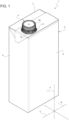
Figure 1 is a schematic perspective view of a package having an opening device according to the present invention, with parts removed for clarity; -
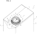
Figure 2 is an enlarged perspective top view of a portion of the package ofFigure 1 with the opening device being in a first configuration, with parts removed for clarity; -
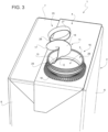
Figure 3 is a perspective top view of the portion ofFigure 2 with the opening device being in a second configuration; and -
Figures 4 and5 are bottom views of the package with the opening device being, respectively, in the first configuration and in a third configuration, with parts removed for clarity. -
Number 1 indicates as a whole a package for a pourable product, in particular a pourable food product, even more particular a liquid food product, comprising: - a (composite)
main body 2, in particular a sealed (composite)main body 2, being filled with a pourable product, in particular a pourable food product, even more particular a liquid food product, and having a designatedpour opening 3 configured to allow for an outflow of the pourable product frommain body 2; and - an
opening device 4, in particular aplastic opening device 4, coupled tomain body 2 and configured to seal the designated pour opening 3 prior to the first-time use ofpackage 1. - In more detail,
main body 2 may be obtained from a packaging material, in particular a composite packaging material, having a multilayer structure (not shown and known as such). - Furthermore,
main body 2 may be obtained from a respective blank. - Preferentially, the packaging material may be provided in the form of a web.
- Moreover,
main body 2 may be obtained by forming a tube from the packaging material, longitudinally sealing the tube, filling the tube with the pourable product and by transversally sealing and cutting the tube. - In further detail, the packaging material may comprise at least one layer of fibrous material, such as e.g. a paper or cardboard, and at least two layers of heat-seal plastic material, e.g. polyethylene, interposing the layer of fibrous material in between one another. One of these two layers of heat-seal plastic material defining the inner face of
main body 2 contacting the pourable product. - Moreover, the packaging material may also comprise a layer of gas- and light-barrier material, e.g. aluminum foil or ethylene vinyl alcohol (EVOH) film, in particular being arranged between one of the layers of the heat-seal plastic material and the layer of fibrous material. Preferentially, the packaging material may also comprise a further layer of heat-seal plastic material being interposed between the layer of gas- and light-barrier material and the layer of fibrous material.
- According to a preferred non-limiting embodiment,
opening device 4 may be applied onto the packaging material and/orbase package 2 prior, during and/or after the formation, filling and sealing ofmain body 2. - Alternatively,
opening device 4 may be applied onto the packaging material prior to arranging the packaging material within or during advancement of the packaging material through a packaging machine for forming, filling and sealingmain bodies 2 from the packaging material. - In particular,
opening device 4 may be fused and/or welded and/or bond and/or molded ontomain body 2 and/or the packaging material and around the designated pour outlet. - With particular reference to
Figure 1 ,main body 2 may extend along a longitudinal axis A, a first transversal axis B and a second transversal axis C. In particular, the extension ofpackage 2 along longitudinal axis A may be larger than the extension ofpackage 2 along first transversal axis B and second transversal axis C. - Preferentially,
main body 2 may be parallelepiped-shaped. Alternatively,main body 2 may have a tubular shape or any other shape. - In more detail,
main body 2 may comprise afirst wall portion 5, in particular being transversal, in particular perpendicular, to longitudinal axis A, and from whichmain body 2 extends along longitudinal axis A. Preferentially,first wall portion 5 may define a support surface ofpackage 1, in particularmain body 2, which is designed to be put in contact with a support, such as e.g. a shelf, in particular when, in use, being e.g. exposed within a sales point or when being stored. In particular, when being arranged on a supportfirst wall portion 5 defines a bottom wall portion. - Furthermore,
main body 2 may also comprise one or morelateral walls 6, in the specific case shown four, being (fixedly) connected tofirst wall portion 5 and extending, in particular substantially parallel to longitudinal axis A, fromfirst wall portion 5. - Additionally,
main body 2 may also comprise asecond wall portion 7 opposite tofirst wall portion 5 and being (fixedly) connected to at least some oflateral walls 6. In particular,lateral walls 6 may be interposed betweenfirst wall portion 5 andsecond wall portion 7. In particular, when being arranged on a support,second wall portion 7 may define a top wall portion. - According to some non-limiting embodiments,
first wall portion 5 andsecond wall portion 7 may be parallel to one another. - According to alternative non-limiting embodiments not shown,
first wall portion 5 andsecond wall portion 7 may be inclined with respect to one another. - According to some non-limiting embodiments,
second wall portion 7 may carry and/or comprise designated pour opening 3. - According to some preferred non-limiting embodiments,
package 1, in particularmain body 2, may comprise aninner space 8 configured to contain and/or containing the pourable product. In particular,first wall portion 5,lateral walls 8 andsecond wall portion 7 delimitinner space 8. - Furthermore,
main body 2 may comprise a separation membrane (not shown and known as such) covering designated pouropening 3. In particular, the separation membrane may separate in the area of, in particular at, designated pour opening 3inner space 8 from an outer environment. Preferentially, the separation membrane may comprise a gas- and light-barrier material, e.g. aluminum foil or ethylene vinyl alcohol (EVOH) film. - Moreover, and as will be disclosed in more detail further below, the separation membrane may be fused together with a portion of
opening device 4. - With particular reference to
Figures 1 to 5 ,opening device 4 comprises at least: - a (plastic)
base frame 10 forcoupling opening device 4 tomain body 2 and about designated pouropening 3; and - a (plastic) covering
membrane 11 rupturably connected tobase frame 10 along a weakening line 12 (of opening device 4) and configured to cover designated pouropening 3. - Moreover, (plastic) weakening
line 12 is configured such that, in use, upon exertion of an opening force on coveringmembrane 11, covering membrane 11 (irreversibly) separates frombase frame 10 along weakeningline 12. In other words, upon exertion of the opening force weakening line 12 (irreversibly) ruptures so as to separate coveringmembrane 11 frombase frame 10 along weakeningline 12. - Furthermore, prior to the first-time use (i.e. prior to exerting the opening force (for the first time)), covering
membrane 11 is designed to cover and seal in cooperation withbase frame 10 the designated pour opening. - Advantageously, weakening
line 12 comprises afirst end 13 and asecond end 14 distinct and separated from one another. In other words, weakeningline 12 does not have an annular configuration and/or a closed-loop configuration. In even other words,first end 13 andsecond end 14 are not in contact with one another. - In particular, weakening
line 12 may be arc-shaped. - Furthermore, covering
membrane 11 is further connected tobase frame 10 along an (unrupturable) tetheringportion 15 extending betweenfirst end 13 andsecond end 14. In particular, tetheringportion 15tethers covering membrane 11 tobase frame 10 even after separation of coveringmembrane 11 frombase frame 10 along weakeningline 12. In this manner, one guarantees that coveringmembrane 11 remains connected to base frame 10 (andmain body 2 andpackage 1 as a whole) avoiding the possibility of an incorrect disposal of coveringmembrane 11. - Furthermore, tethering
portion 15 is configured such that, in use, upon exertion of the opening force on coveringmembrane 11, coveringmembrane 11 remains attached tobase frame 10 along tetheringportion 15. - It is to be noted that the term unrupturable indicates that upon a normal use by a
user tethering portion 15 does not rupture. In other words, the opening force suited to allow for the rupturing of weakeningline 12 does not allow to rupturetethering portion 15. - Moreover, weakening
line 12 together with tetheringportion 15 may define an annular shape and while, in use, upon exertion of the opening force the weakeningline 12 ruptures, tetheringportion 15 remains intact. - Additionally, tethering
portion 15 may be in contact withfirst end 13 andsecond end 14. - Additionally, the thickness of weakening
line 12 may be smaller than the thickness of tetheringportion 15. - With particular reference to
Figures 2 to 5 , upon separation of coveringmembrane 11 frombase frame 10 along weakeningline 12, coveringmembrane 11 is angularly moveable around a hinge axis E defined by tetheringportion 15. - In more detail, covering
membrane 11 is angularly moveable from a closing position (seeFigures 2 and4 ) in which coveringmembrane 11 covers designated pour opening 3 to an opening position in which coveringmembrane 11 frees designated pour opening 3. In particular, coveringmembrane 11 is in the closing position, with coveringmembrane 11 being connected tobase frame 10 along weakeningline 12. Even more particular, coveringmembrane 11 is in the closing position, with weakeningline 12 being intact. - Additionally, and with particular reference to
Figures 3 and5 , once coveringmembrane 11 is separated frombase frame 10 along weakeningline 12, coveringmembrane 11 is angularly moveable between the opening position and a re-closing position, in which coveringmembrane 11 covers designated pour opening 3. - With particular reference to
Figures 2 and4 , coveringmembrane 11 may be configured such that prior to the first-time use (i.e. prior to the rupturing of weakening line 12) coveringmembrane 11 is positioned in the closing position and is designed to cover designated pouringoutlet 3 and to also seal designated pouringoutlet 3 in cooperation withbase frame 10. Additionally, and with particular reference toFigure 5 , coveringmembrane 11 may be designed such that once coveringmembrane 11 is separated frombase frame 10 along weakening line 12 (i.e. weakeningline 12 is ruptured) coveringmembrane 11 may be in the re-closing position, in which coveringmembrane 11 covers designated pouringoutlet 3, but does not seal designated pouringoutlet 3 anymore. - Preferentially, covering
membrane 11 may be biased into the re-closing position, i.e. in the absence of the application of an external force on coveringmembrane 11, coveringmembrane 11 returns back to the re-closing position. - Advantageously and with particular reference to
Figure 3 ,opening device 4 may comprise a retaining element 16 (see further below for more details) configured to interact with coveringmembrane 11 so as to retain coveringmembrane 11 in the opening position, in particular so as to guarantee that coveringmembrane 11 does not disturb the outpouring of the pourable product frompackage 1, in particularmain body 2. - With particular reference to
Figures 2 to 5 , coveringmembrane 11 comprises afirst portion 17 and asecond portion 18 being rupturably connected to one another along anauxiliary weakening line 19.Auxiliary weakening line 19 is configured such that, in use, upon exertion of the opening force, and in particular (substantially) simultaneously to the separation of coveringmembrane 11 frombase frame 10,first portion 17 andsecond portion 18 separate from one another alongauxiliary weakening line 19. - Moreover,
auxiliary weakening line 19 may extend fromsecond end 14. In particular,auxiliary weakening line 19 andsecond end 14 are (integrally) connected to one another. - Furthermore,
auxiliary weakening line 19 may extend fromsecond end 14 towards, in particular to, acenter 20 of coveringmembrane 11. - Additionally,
auxiliary weakening line 19 may be transversal, in particular perpendicular, to weakeningline 12. - Advantageously,
first portion 17 andsecond portion 18 may be configured to interact with retainingelement 16 for retaining coveringmembrane 11 in the opening position. - In particular,
first portion 17 andsecond portion 18 may be configured to hook up with retainingelement 16 for retaining coveringmembrane 11 in the opening position. In other words,first portion 17 andsecond portion 18 may be arrangeable such to interpose and/or clamp at least a portion of retainingelement 16 between one another for retaining coveringmembrane 11 in the opening position. - According to some non-limiting embodiments, covering
membrane 11 is (substantially) flush withmain body 2, in particularsecond wall portion 7, in particular when being in the closed position. - Furthermore, covering
membrane 11 may be fused with the separation membrane. In other words, separation membrane may be considered to be part of coveringmembrane 11. - With particular reference to
Figures 2 and3 ,opening device 4 may further comprise anopening element 25 connected to coveringmembrane 11 and configured to allow for the exertion of the opening force on coveringmembrane 11. In particular, openingelement 25 may be configured to be operated by a consumer so as to exert the opening force. - In more detail, opening
element 25 may comprise apull leg 26, in particular asingle pull leg 26, connected to coveringmembrane 11, in particular to a peripheral portion of coveringmembrane 11. Additionally, openingelement 25 may comprise agripping element 27, for example a ring, connected to pullleg 26 and being designed to be gripped by the consumer. - Moreover, pull
leg 26 may be arranged at a peripheral portion of coveringmembrane 11 being opposed to a portion of coveringmembrane 11 being integrally connected to tetheringportion 15. - Advantageously, pull
leg 26 may transversally, in particular (substantially) perpendicularly, extend from coveringmembrane 11. - Preferentially, opening
element 25, inparticular pull leg 26, may be connected to coveringmembrane 11 at a connecting point, in particular a single connecting point. - Moreover, pull
leg 26 may be arranged adjacent tosecond end 14 andauxiliary weakening line 19. - In further detail and with particular reference to
Figures 2 and3 ,opening device 4 may further comprise acollar 28 extending frombase frame 10 and having anoutlet 29, in particular being aligned, even more particular being coaxial, with respect to designated pouringoutlet 3. In particular,collar 28 being designed to allow for a controlled outpouring of the pourable product frompackage 1, in particularmain body 2. - According to some preferred non-limiting embodiments,
collar 28 may define retainingelement 16. In this manner, one avoids providingopening device 4 with further components. In this case,first portion 17 andsecond portion 18 may be arranged and/or arrangeable so as to contactcollar 28 from opposite sides thereof for retaining coveringmembrane 11 in the opening position. - Preferentially,
base frame 10, coveringmembrane 11, weakeningline 12,tethering portion 15, and inparticular collar 28, may be obtained, in particular by molding, as a single piece. - Preferentially,
base frame 10, coveringmembrane 11, weakeningline 12,tethering portion 15, and inparticular collar 28, may be molded ontomain body 2 and/or onto the packaging material from whichmain body 2 is formed. - With particular reference to
Figure 1 ,opening device 4 may also comprise alid 30 coupled and/or couplable tocollar 28 and configured to selectively close andopen outlet 29. - According to the specific embodiment shown,
lid 30 is of the screw-lid type. Alternatively,lid 30 could be of any other type. - In further detail,
opening device 4 may also comprise acoupling ring 31 coupled to and arranged aroundcollar 28. In particular,lid 30 may be tethered tocoupling ring 31. - Preferentially,
lid 30 may be at least arrangeable in a closed position, in whichlid 30covers outlet 29, and an open position, in whichlid 30 is removed fromoutlet 29. - In use, a consumer in order to allow for the outpouring of the pourable product from
package 1 needs to manipulate coveringmembrane 11. - In more detail, a consumer needs to exert the opening force, in particular by relying on opening
element 25, on coveringmembrane 11 so as to separate coveringmembrane 11 frombase frame 10 along weakeningline 12. Moreover, the exertion of the opening force also leads to the separation offirst portion 17 andsecond portion 18 alongauxiliary weakening line 19. - Moreover, prior to being able to manipulate covering
membrane 11 the user needs to arrangelid 30 in the open position. - Additionally, during the outpouring of the pourable product, covering
membrane 11 may be retained by retainingelement 16, inparticular collar 28, in the opening position. - After the outpouring the consumer can arrange covering
membrane 11 in the re-closing position, and in particular also arrangelid 30 in the closed position. - The advantages of
opening device 4 and/or ofpackage 1 according to the present invention will be clear from the foregoing description. - In particular, by having
tethering portion 15 or in other words by having anon-annular weakening line 12 one guarantees that coveringmembrane 11 does not need to be disposed separately from the other portions ofpackage 1. - Another advantage resides in the presence of
first portion 17 andsecond portion 18, which may be arranged and/or arrangeable so as to contact retainingelement 16, inparticular collar 28, from opposite sides thereof for maintaining coveringmembrane 11 in the opening position. - Clearly, changes may be made to opening
device 4 and/orpackage 1 as described herein without, however, departing from the scope of protection as defined in the accompanying claims.
Claims (14)
- - Opening device (4) for a package (1) being filled with a pourable product and having a main body (2) provided with a designated pour opening (3);
the opening device (4) comprises at least:- a base frame (10) for coupling the opening device (4) to the main body (2) and about the designated pour opening (3); and- a covering membrane (11) rupturably connected to the base frame (10) along a weakening line (12) and configured to cover the designated pour opening (3);wherein the weakening line (12) comprises a first end (13) and a second end (14) distinct and separated from one another;wherein the covering membrane (11) is further connected to the base frame (10) along a tethering portion (15) extending between the first end (13) and the second end (14);wherein the weakening line (12) and the tethering portion (15) are configured such that, in use, upon exertion of an opening force on the covering membrane (11), the covering membrane (11) separates from the base frame (10) along the weakening line (12) and remains attached to the base frame (10) along the tethering portion (15);characterized in that the covering membrane (11) comprises a first portion (17) and a second portion (18) being rupturably connected to one another along an auxiliary weakening line (19);wherein the auxiliary weakening line (19) is configured such that, in use, upon exertion of the opening force, the first portion (17) and the second portion (18) separate from one another along the auxiliary weakening line (19). - - Opening device according to claim 1, wherein upon separation of the covering membrane (11) from the base frame (10) along the weakening line (12), the covering membrane (11) is angularly moveable around a hinge axis (E) defined by the tethering portion (15).
- - Opening device according to claim 2, wherein the covering membrane (11) is angularly moveable from a closing position, in which the covering membrane (11) covers the designated pour opening (3) and seals the designated pouring outlet (3) in cooperation with the base frame (10), to an opening position, in which the covering membrane (11) frees the designated pour opening (3).
- - Opening device according to claim 3, wherein after separation of the covering membrane (11) from the base frame (10) along the weakening line (12), the covering membrane (11) is moveable between the opening position and a re-closing position, in which the covering membrane (11) covers the designated pouring outlet (3), but does not seal the designated pouring outlet (3) in cooperation with the base frame (10).
- - Opening device according to any one of the preceding claims, wherein the weakening line (12) is arc-shaped.
- - Opening device according to any one of the preceding claims, wherein the auxiliary weakening line (19) extends from the second end (14) of the weakening line (12) towards a center (20) of the covering membrane (11).
- - Opening device according to any one of the preceding claims, and further comprising a retaining element (16) configured to interact with the covering membrane (11) so as to retain the covering membrane (11) in the opening position;
wherein the first portion (17) and the second portion (18) are configured to interact in cooperation with one another with the retaining element (16) for retaining the covering membrane (11) in the opening position. - - Opening device according to claim 7, and further comprising a collar (28) extending from the base frame (10);
wherein the collar (28) defines the retaining element (16) . - - Opening device according to claim 7 or 8, wherein the first portion (17) and the second portion (18) clamp at least a portion of the retaining element (16) between one another for retaining the covering membrane (11) in the opening position.
- - Opening device according to any one of the preceding claims, and further comprising an opening element (25) connected to the covering membrane (11) and configured to allow for the exertion of the opening force on the covering membrane (11), the opening element (25) being connected to the covering membrane (11) at a connecting point arranged adjacent to the second end (14).
- - Opening device according to any one of the preceding claims, wherein the weakening line (12) together with the tethering portion (15) defines an annular shape.
- - Opening device according to any one of the preceding claims, wherein the tethering portion (15) is in contact with the first end (13) and the second end (14).
- - Opening device according to any one of the preceding claims, wherein the thickness of the weakening line (12) is smaller than the thickness of the tethering portion (15).
- - Package (1) filled with a pourable product and comprising at least one opening device (4) according to any one of the preceding claims.
Applications Claiming Priority (1)
| Application Number | Priority Date | Filing Date | Title |
|---|---|---|---|
| EP21169406 | 2021-04-20 |
Publications (3)
| Publication Number | Publication Date |
|---|---|
| EP4079652A1 EP4079652A1 (en) | 2022-10-26 |
| EP4079652C0 EP4079652C0 (en) | 2023-11-15 |
| EP4079652B1 true EP4079652B1 (en) | 2023-11-15 |
Family
ID=75625350
Family Applications (1)
| Application Number | Title | Priority Date | Filing Date |
|---|---|---|---|
| EP22167960.8A Active EP4079652B1 (en) | 2021-04-20 | 2022-04-12 | Opening device for a package and package having an opening device |
Country Status (2)
| Country | Link |
|---|---|
| EP (1) | EP4079652B1 (en) |
| WO (1) | WO2022223374A1 (en) |
Family Cites Families (3)
| Publication number | Priority date | Publication date | Assignee | Title |
|---|---|---|---|---|
| JPH0789535A (en) * | 1993-06-30 | 1995-04-04 | Dainippon Printing Co Ltd | Brick-form paper container |
| AU4102096A (en) * | 1994-11-07 | 1996-05-31 | Capitol Spouts, Inc. | Container having improved reclosable pour spout mounted thereon and process therefor |
| EP3715271A1 (en) * | 2019-03-26 | 2020-09-30 | Tetra Laval Holdings & Finance S.A. | Opening device for a package containing a pourable product |
-
2022
- 2022-04-12 WO PCT/EP2022/059782 patent/WO2022223374A1/en active Application Filing
- 2022-04-12 EP EP22167960.8A patent/EP4079652B1/en active Active
Also Published As
| Publication number | Publication date |
|---|---|
| EP4079652C0 (en) | 2023-11-15 |
| EP4079652A1 (en) | 2022-10-26 |
| WO2022223374A1 (en) | 2022-10-27 |
Similar Documents
| Publication | Publication Date | Title |
|---|---|---|
| EP3892562A1 (en) | Lid assembly for a package, lid-spout group for a package and package having a lid-spout group | |
| EP3892561B1 (en) | Lid assembly for a spout of a package, lid-spout group for a package and package having a lid assembly | |
| EP3892560A1 (en) | Lid-spout assembly for a package and package having a lid-spout assembly | |
| EP4079652B1 (en) | Opening device for a package and package having an opening device | |
| EP3892559B1 (en) | Lid-spout assembly for a package and package therewith | |
| EP3868680A1 (en) | Spout for a container and package-spout assembly | |
| EP3892564A1 (en) | Spout for a package, lid-spout assembly for a package and package having a spout | |
| EP4159631B1 (en) | Opening device for a package, mold for molding an opening device for a package and package having an opening device | |
| EP4159634B1 (en) | Opening device for a package, mold for molding an opening device for a package and package having an opening device | |
| US20230137895A1 (en) | Spout for a package, lid-spout assembly for a package and package having a spout | |
| EP4177181A1 (en) | Opening device for a package and package having an opening device | |
| EP4001150A1 (en) | Lid-spout assembly for a package and package having a lid-spout assembly | |
| EP4159633A1 (en) | Opening device for a package, mold for molding an opening device for a package and package having an opening device | |
| EP3915894A1 (en) | Lid-spout assembly for a package and package having a lid-spout assembly | |
| EP4001149A1 (en) | Opening device for a package and package having an opening device | |
| US20230115201A1 (en) | Lid assembly for a container, container having a lid assembly and method of coupling a lid assembly to a spout | |
| CN118019694A (en) | Opening device for a package, mould for moulding an opening device for a package and package with an opening device |
Legal Events
| Date | Code | Title | Description |
|---|---|---|---|
| PUAI | Public reference made under article 153(3) epc to a published international application that has entered the european phase |
Free format text: ORIGINAL CODE: 0009012 |
|
| STAA | Information on the status of an ep patent application or granted ep patent |
Free format text: STATUS: THE APPLICATION HAS BEEN PUBLISHED |
|
| AK | Designated contracting states |
Kind code of ref document: A1 Designated state(s): AL AT BE BG CH CY CZ DE DK EE ES FI FR GB GR HR HU IE IS IT LI LT LU LV MC MK MT NL NO PL PT RO RS SE SI SK SM TR |
|
| STAA | Information on the status of an ep patent application or granted ep patent |
Free format text: STATUS: REQUEST FOR EXAMINATION WAS MADE |
|
| 17P | Request for examination filed |
Effective date: 20230426 |
|
| RBV | Designated contracting states (corrected) |
Designated state(s): AL AT BE BG CH CY CZ DE DK EE ES FI FR GB GR HR HU IE IS IT LI LT LU LV MC MK MT NL NO PL PT RO RS SE SI SK SM TR |
|
| GRAP | Despatch of communication of intention to grant a patent |
Free format text: ORIGINAL CODE: EPIDOSNIGR1 |
|
| STAA | Information on the status of an ep patent application or granted ep patent |
Free format text: STATUS: GRANT OF PATENT IS INTENDED |
|
| RIC1 | Information provided on ipc code assigned before grant |
Ipc: B65D 55/16 20060101ALI20230615BHEP Ipc: B65D 5/74 20060101AFI20230615BHEP |
|
| INTG | Intention to grant announced |
Effective date: 20230703 |
|
| GRAS | Grant fee paid |
Free format text: ORIGINAL CODE: EPIDOSNIGR3 |
|
| GRAA | (expected) grant |
Free format text: ORIGINAL CODE: 0009210 |
|
| STAA | Information on the status of an ep patent application or granted ep patent |
Free format text: STATUS: THE PATENT HAS BEEN GRANTED |
|
| AK | Designated contracting states |
Kind code of ref document: B1 Designated state(s): AL AT BE BG CH CY CZ DE DK EE ES FI FR GB GR HR HU IE IS IT LI LT LU LV MC MK MT NL NO PL PT RO RS SE SI SK SM TR |
|
| REG | Reference to a national code |
Ref country code: CH Ref legal event code: EP Ref country code: GB Ref legal event code: FG4D |
|
| REG | Reference to a national code |
Ref country code: DE Ref legal event code: R096 Ref document number: 602022000982 Country of ref document: DE |
|
| REG | Reference to a national code |
Ref country code: IE Ref legal event code: FG4D |
|
| U01 | Request for unitary effect filed |
Effective date: 20231130 |
|
| U07 | Unitary effect registered |
Designated state(s): AT BE BG DE DK EE FI FR IT LT LU LV MT NL PT SE SI Effective date: 20231206 |
|
| PG25 | Lapsed in a contracting state [announced via postgrant information from national office to epo] |
Ref country code: GR Free format text: LAPSE BECAUSE OF FAILURE TO SUBMIT A TRANSLATION OF THE DESCRIPTION OR TO PAY THE FEE WITHIN THE PRESCRIBED TIME-LIMIT Effective date: 20240216 |
|
| PG25 | Lapsed in a contracting state [announced via postgrant information from national office to epo] |
Ref country code: IS Free format text: LAPSE BECAUSE OF FAILURE TO SUBMIT A TRANSLATION OF THE DESCRIPTION OR TO PAY THE FEE WITHIN THE PRESCRIBED TIME-LIMIT Effective date: 20240315 |
|
| PG25 | Lapsed in a contracting state [announced via postgrant information from national office to epo] |
Ref country code: IS Free format text: LAPSE BECAUSE OF FAILURE TO SUBMIT A TRANSLATION OF THE DESCRIPTION OR TO PAY THE FEE WITHIN THE PRESCRIBED TIME-LIMIT Effective date: 20240315 Ref country code: GR Free format text: LAPSE BECAUSE OF FAILURE TO SUBMIT A TRANSLATION OF THE DESCRIPTION OR TO PAY THE FEE WITHIN THE PRESCRIBED TIME-LIMIT Effective date: 20240216 |