EP4234397B1 - Hélicoptère combiné - Google Patents
Hélicoptère combiné Download PDFInfo
- Publication number
- EP4234397B1 EP4234397B1 EP21930222.1A EP21930222A EP4234397B1 EP 4234397 B1 EP4234397 B1 EP 4234397B1 EP 21930222 A EP21930222 A EP 21930222A EP 4234397 B1 EP4234397 B1 EP 4234397B1
- Authority
- EP
- European Patent Office
- Prior art keywords
- propeller
- propeller blade
- thrust
- blade
- angle
- Prior art date
- Legal status (The legal status is an assumption and is not a legal conclusion. Google has not performed a legal analysis and makes no representation as to the accuracy of the status listed.)
- Active
Links
Images
Classifications
-
- B—PERFORMING OPERATIONS; TRANSPORTING
- B64—AIRCRAFT; AVIATION; COSMONAUTICS
- B64C—AEROPLANES; HELICOPTERS
- B64C27/00—Rotorcraft; Rotors peculiar thereto
- B64C27/22—Compound rotorcraft, i.e. aircraft using in flight the features of both aeroplane and rotorcraft
- B64C27/26—Compound rotorcraft, i.e. aircraft using in flight the features of both aeroplane and rotorcraft characterised by provision of fixed wings
-
- B—PERFORMING OPERATIONS; TRANSPORTING
- B64—AIRCRAFT; AVIATION; COSMONAUTICS
- B64C—AEROPLANES; HELICOPTERS
- B64C11/00—Propellers, e.g. of ducted type; Features common to propellers and rotors for rotorcraft
- B64C11/16—Blades
- B64C11/18—Aerodynamic features
-
- B—PERFORMING OPERATIONS; TRANSPORTING
- B64—AIRCRAFT; AVIATION; COSMONAUTICS
- B64C—AEROPLANES; HELICOPTERS
- B64C11/00—Propellers, e.g. of ducted type; Features common to propellers and rotors for rotorcraft
- B64C11/16—Blades
- B64C11/20—Constructional features
-
- B—PERFORMING OPERATIONS; TRANSPORTING
- B64—AIRCRAFT; AVIATION; COSMONAUTICS
- B64C—AEROPLANES; HELICOPTERS
- B64C11/00—Propellers, e.g. of ducted type; Features common to propellers and rotors for rotorcraft
- B64C11/30—Blade pitch-changing mechanisms
-
- B—PERFORMING OPERATIONS; TRANSPORTING
- B64—AIRCRAFT; AVIATION; COSMONAUTICS
- B64C—AEROPLANES; HELICOPTERS
- B64C11/00—Propellers, e.g. of ducted type; Features common to propellers and rotors for rotorcraft
- B64C11/46—Arrangements of, or constructional features peculiar to, multiple propellers
-
- B—PERFORMING OPERATIONS; TRANSPORTING
- B64—AIRCRAFT; AVIATION; COSMONAUTICS
- B64C—AEROPLANES; HELICOPTERS
- B64C27/00—Rotorcraft; Rotors peculiar thereto
- B64C27/32—Rotors
- B64C27/46—Blades
- B64C27/467—Aerodynamic features
-
- B—PERFORMING OPERATIONS; TRANSPORTING
- B64—AIRCRAFT; AVIATION; COSMONAUTICS
- B64C—AEROPLANES; HELICOPTERS
- B64C27/00—Rotorcraft; Rotors peculiar thereto
- B64C27/32—Rotors
- B64C27/46—Blades
- B64C27/473—Constructional features
-
- B—PERFORMING OPERATIONS; TRANSPORTING
- B64—AIRCRAFT; AVIATION; COSMONAUTICS
- B64C—AEROPLANES; HELICOPTERS
- B64C27/00—Rotorcraft; Rotors peculiar thereto
- B64C27/82—Rotorcraft; Rotors peculiar thereto characterised by the provision of an auxiliary rotor or fluid-jet device for counter-balancing lifting rotor torque or changing direction of rotorcraft
- B64C2027/8236—Rotorcraft; Rotors peculiar thereto characterised by the provision of an auxiliary rotor or fluid-jet device for counter-balancing lifting rotor torque or changing direction of rotorcraft including pusher propellers
-
- B—PERFORMING OPERATIONS; TRANSPORTING
- B64—AIRCRAFT; AVIATION; COSMONAUTICS
- B64C—AEROPLANES; HELICOPTERS
- B64C27/00—Rotorcraft; Rotors peculiar thereto
- B64C27/82—Rotorcraft; Rotors peculiar thereto characterised by the provision of an auxiliary rotor or fluid-jet device for counter-balancing lifting rotor torque or changing direction of rotorcraft
- B64C2027/8263—Rotorcraft; Rotors peculiar thereto characterised by the provision of an auxiliary rotor or fluid-jet device for counter-balancing lifting rotor torque or changing direction of rotorcraft comprising in addition rudders, tails, fins, or the like
- B64C2027/8281—Rotorcraft; Rotors peculiar thereto characterised by the provision of an auxiliary rotor or fluid-jet device for counter-balancing lifting rotor torque or changing direction of rotorcraft comprising in addition rudders, tails, fins, or the like comprising horizontal tail planes
Definitions
- the present disclosure relates to a compound helicopter.
- a rotary wing aircraft of PTL 1 As a conventional compound helicopter, a rotary wing aircraft of PTL 1 is known.
- the rotary wing aircraft includes a body, a main rotor, a pair of propellers for propulsion, and a stabilizer.
- the main rotor is arranged on the body.
- the pair of propellers for propulsion are arranged at both sides of the body.
- the stabilizer is arranged at a rear end of the body.
- Each of the propellers for propulsion includes blades, and a flap is disposed at the stabilizer.
- the pair of propellers for propulsion and the flap are adjusted for flight stabilization.
- PTL 1 does not describe the improvement of a flight efficiency by the propellers for propulsion.
- US 2018/057158 A1 discloses a rotorcraft having a fuselage surmounted by a main rotor.
- the rotorcraft has a first propeller and a second propeller driven in rotation respectively about a first secondary axis of rotation and a second secondary axis of rotation.
- a mobility system turns the second propeller relative to the fuselage, the mobility system turning the second secondary axis of rotation relative to the fuselage from a first position where the second propeller exerts thrust in a first direction to a second position where the second propeller exerts thrust in a second direction opposite to the first direction.
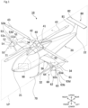
- a compound helicopter 10 according to Embodiment 1 is an aircraft including components that generate propulsive force in addition to components that generate lift force. As shown in FIG. 1 , the compound helicopter 10 includes a body 20, a main wing 30, a main rotor 40, a pair of propellers 50 and 60 that are different in specifications from each other, a landing gear 70, an empennage 80, and a controller 90.
- the main rotor 40 and the landing gear 70 are arranged so as to sandwich the body 20 in an upper-lower direction.
- a side of the landing gear 70 which side is closer to the main rotor 40 is referred to as an upper side, and its opposite side is referred to as a lower side.
- the first propeller 50 and the second propeller 60 are arranged so as to sandwich the body 20 in a left-right direction.
- the first propeller 50 is arranged at a right side of the main wing 30 in a proceeding direction
- the second propeller 60 is arranged at a left side of the main wing 30 in the proceeding direction.
- the proceeding direction is regarded as positive
- the first propeller 50 generates only positive thrust
- the second propeller 60 generates positive thrust and negative thrust. Therefore, the first propeller 50 and the second propeller 60 are different in specifications from each other.
- the "positive thrust” is also referred to as "forward thrust”
- the "negative thrust” is also referred to as "backward thrust.”
- the body 20 extends from a nose 21 toward a tail 22 in an aircraft axis direction.
- a plane is defined as a virtual symmetry plane VP, that is orthogonal to the left-right direction at a middle point of the body 20 in the left-right direction
- the body 20 has a shape symmetrical with respect to the virtual symmetry plane VP.
- the shape of the body 20 may be, for example, a prolate spheroid that is long in a front-rear direction or may not be symmetrical with respect to the virtual symmetry plane VP.
- a main driving structure 41 that rotates the main rotor 40 is arranged at an upper portion of the body 20.
- the main driving structure 41 includes, for example, a prime mover, such as an engine.
- the main rotor 40 includes a main rotor rotating shaft 42 and four main rotor blades 43 and generates lift force.
- the main rotor rotating shaft 42 is arranged at a middle of the body 20 in the left-right direction and at or in front of a middle of the body 20 in the front-rear direction.
- the main rotor rotating shaft 42 includes a lower end attached to an output portion of the main driving structure 41 and extends in a vertical direction.
- the main rotor rotating shaft 42 may be a tilt rotor that is inclined relative to the upper-lower direction.
- Each main rotor blade 43 is, for example, a rectangular elongated member and includes one end portion connected to the main rotor rotating shaft 42.
- the main rotor blades 43 are arranged at regular intervals in a circumferential direction about the main rotor rotating shaft 42 and extend radially from the main rotor rotating shaft 42.
- An output of the main driving structure 41 is transmitted to the main rotor blades 43, through the main rotor rotating shaft 42, to rotate the main rotor blades 43 about the main rotor rotating shaft 42.
- Pitch angles of the main rotor blades 43 may be controlled such that the lift force generated by the main rotor 40 becomes maximum.
- the main wing 30 includes a first main wing portion 31 and a second main wing portion 32, and generates lift force during forward flight.
- the first main wing portion 31 extends from the right side in a proceeding-direction of the body 20, and the second main wing portion 32 extends from the left side in a proceeding-direction of the body 20.
- the first main wing portion 31 and the second main wing portion 32 are formed symmetrical with respect to the virtual symmetry plane VP, and extend in respective directions intersecting with (for example, orthogonal to) the virtual symmetry plane VP.
- Each of the main wing portions 31 and 32 includes a wing root 33 and a wing tip 34, and the wing root 33 is connected to the body 20.
- each of the main wing portions 31 and 32 has such a trapezoidal shape that a dimension of the wing root 33 in the front-rear direction is larger than a dimension of the wing tip 34 in the front-rear direction.
- the first propeller 50 that generates propulsive force and a first driving structure 51 that rotates the first propeller 50 are disposed at the wing tip 34 of the first main wing portion 31.
- the second propeller 60 that generates propulsive force and a second driving structure 61 that rotates the second propeller 60 are disposed at the wing tip 34 of the second main wing portion 32.
- the first driving structure 51 and the second driving structure 61 are driven by, for example, a drive shaft connected to the main driving structure 41.
- the first propeller 50 includes a first rotating shaft 52 and four first propeller blades 53.
- the second propeller 60 includes a second rotating shaft 62 and four second propeller blades 63.
- the first rotating shaft 52 and the second rotating shaft 62 extend in a direction parallel to the aircraft axis direction.
- a rear end portion of the first rotating shaft 52 is attached to an output portion of the first driving structure 51
- a rear end portion of the second rotating shaft 62 is attached to an output portion of the second driving structure 61.
- the rotating shaft 52 rotates by the driving structure 51 at, for example, a fixed speed
- the rotating shaft 62 rotates by the driving structure 61 at, for example, a fixed speed.
- the first propeller blades 53 are attached to a front end portion of the first rotating shaft 52 and arranged at regular intervals in the circumferential direction about the first rotating shaft 52.
- the second propeller blades 63 are attached to a front end portion of the second rotating shaft 62 and arranged at regular intervals in the circumferential direction about the second rotating shaft 62.
- Each of the front end portion of the rotating shaft 52, to which the propeller blades 53 are attached, and the front end portion of the rotating shaft 62, to which the propeller blades 63 are attached, has a pyramid shape, such as a cone shape, which projects forward.
- the propeller blades 53 rotate about the rotating shaft 52, and the propeller blades 63 rotate about the rotating shaft 62. At this time, the first propeller blade 53 rotates counterclockwise at a fixed speed v, and the second propeller blade 63 rotates clockwise at the fixed speed v. As above, the first propeller blade 53 and the second propeller blade 63 rotate in respective directions opposite to each other at the same rotational speed.
- a first pitch variable structure 54 that varies the pitch angles of the first propeller blades 53, is disposed at a portion to which the first propeller blades 53 are attached.
- a second pitch variable structure 64 that varies the pitch angles of the second propeller blades 63, is disposed at a portion to which the second propeller blades 63 are attached. The direction and magnitude of propulsive force generated by each propeller blade 53 and the direction and magnitude of propulsive force generated by each propeller blade 63 are controlled by changing the pitch angles.
- the first pitch variable structure 54 sets the first propeller blade 53 to the positive pitch angle to make the first propeller blade 53 generate forward thrust (positive thrust).
- the second pitch variable structure 64 sets the second propeller blade 63 to the positive or negative pitch angle in accordance with a flight state, to make the second propeller blade 63 generate forward thrust (positive thrust) or backward thrust (negative thrust).
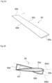
- first and second propeller blades 53 and 63 are smaller than the main rotor blades 43, are rectangular, and extend radially from the respective rotating shafts 52 and 62.
- Each propeller blade 53 includes a base end portion 53a and a tip portion 53b at both end portions thereof in a longitudinal direction.
- Each propeller blade 63 includes a base end portion 63a and a tip portion 63b at both end portions thereof in the longitudinal direction.
- the base end portions 53a of the propeller blades 53 are connected to the rotating shaft 52, and the base end portions 63a of the propeller blades 63 are connected to the rotating shaft 62.
- each first propeller blade 53 includes a leading edge 53c and a trailing edge 53d
- each second propeller blade 63 includes a leading edge 63c and a trailing edge 63d.
- the leading edge 53c is connected to one end of the base end portion 53a and one end of the tip portion 53b
- the leading edge 63c is connected to one end of the base end portion 63a and one end of the tip portion 63b.
- the trailing edge 53d is connected to the other end of the base end portion 53a and the other end of the tip portion 53b
- the trailing edge 63d is connected to the other end of the base end portion 63a and the other end of the tip portion 63b.
- a blade section of the first propeller blade 53 has a round shape at the leading edge 53c and a sharp shape at the trailing edge 53d, and a thickness of the first propeller blade 53 is larger at the leading edge 53c than at the trailing edge 53d.
- a blade section of the second propeller blade 63 has a round shape at the leading edge 63c and a sharp shape at the trailing edge 63d, and a thickness of the second propeller blade 63 is larger at the leading edge 63c than at the trailing edge 63d.
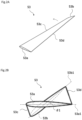
- An angle of attack of the first propeller blade 53 decreases from the base end portion 53a to the tip portion 53b, i.e., is designed as washout.
- An angle of attack of the second propeller blade 63 decreases from the base end portion 63a to the tip portion 63b, i.e., is designed as washout.
- a washout angle that is a difference between an angle of incidence of the base end portion 53a of the first propeller blade 53 and an angle of incidence of the tip portion 53b of the first propeller blade 53, is an acute angle between a chord line 53a1 of the base end portion 53a and a chord line 53b1 of the tip portion 53b and is, for example, 10 degrees or more and 50 degrees or less.
- a washout angle that is a difference between an angle of incidence of the base end portion 63a of the second propeller blade 63 and an angle of incidence of the tip portion 63b of the second propeller blade 63 is an acute angle between a chord line 63a1 of the base end portion 63a and a chord line 63b1 of the tip portion 63b and is, for example, 10 degrees or more and 50 degrees or less.
- the chord line 53a1 is a line connecting the leading edge 53c and the trailing edge 53d at the base end portion 53a.
- the chord line 53b1 is a line connecting the leading edge 53c and the trailing edge 53d at the tip portion 53b.
- the chord line 63a1 is a line connecting the leading edge 63c and the trailing edge 63d at the base end portion 63a.
- the chord line 63b1 is a line connecting the leading edge 63c and the trailing edge 63d at the tip portion 63b.
- Specifications of the first propeller 50 are different form specifications of the second propeller 60. Specifically, the specifications are set such that the negative thrust generated by the second propeller 60 is larger than the negative thrust generated the first propeller 50 under conditions that: the main rotor 40 rotates counterclockwise; the pitch angles of the first propeller blades 53 and the pitch angles of the second propeller blades 63 are set to the negative pitch angles; and the first propeller blades 53 and the second propeller blades 63 rotate at the same rotational speed.
- the specifications are set such that a difference between an absolute value of thrust generated when the main rotor 40 rotates counterclockwise, the pitch angles of the first propeller blades 53 and the pitch angles of the second propeller blades 63 are set to the positive pitch angles, and the first propeller blades 53 and the second propeller blades 63 rotate at the same rotational speed and an absolute value of thrust generated when the pitch angles of the first propeller blades 53 and the pitch angles of the second propeller blades 63 are set to the negative pitch angles, and the first propeller blades 53 and the second propeller blades 63 rotate at the same rotational speed is smaller in the second propeller 60 than in the first propeller 50.
- a washout angle ⁇ 2 of the second propeller blade 63 is smaller than a washout angle ⁇ 1 of the first propeller blade 53.
- the empennage 80 includes a vertical stabilizer 81 and a horizontal stabilizer 82 and has a T shape disposed at the tail 22 of the body 20.
- the vertical stabilizer 81 When the main rotor 40 rotates counterclockwise, the vertical stabilizer 81 generates lift force acting toward the right side in a proceeding-direction.
- the landing gear 70 is disposed at a lower portion of the body 20.
- a landing foot such as a skid, is used as the landing gear 70.
- the landing gear 70 is an apparatus that receives impact and supports the body 20 and the like, when the compound helicopter 10 lands on the ground.
- the controller 90 is a calculation processing unit, such as a processor, which is arranged in the body 20 and controls respective components of the compound helicopter 10 for flight.
- the controller 90 controls the respective components, such as the main driving structure 41 and the pitch variable structures 54 and 64, based on outputs from a maneuvering device, various sensors, and the like.
- circuitry or processing circuitry which includes general purpose processors, special purpose processors, integrated circuits, ASICs ("Application Specific Integrated Circuits"), conventional circuitry and/or combinations thereof which are configured or programmed to perform the disclosed functionality.
- Processors are considered processing circuitry or circuitry as they include transistors and other circuitry therein.
- the circuitry, units, or means are hardware that carry out or are programmed to perform the recited functionality.
- the hardware may be any hardware disclosed herein or otherwise known which is programmed or configured to carry out the recited functionality.
- the hardware is a processor which may be considered a type of circuitry
- the circuitry, means, or units are a combination of hardware and software, the software being used to configure the hardware and/or processor.
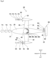
- FIG. 4 is a diagram schematically showing forces generated during the flight of the compound helicopter 10 and shows propulsive force and some forces which contribute to yaw rotation of an airframe.
- each main rotor blade 43 rotates about the main rotor rotating shaft 42 from the tail 22 side (rear side) of the body 20 through the first main wing portion 31 side (right side) to the nose 21 side (front side) of the body 20.
- each of the first propeller 50 and the second propeller 60 rotates at a fixed speed in a fixed direction.
- the first propeller 50 and the second propeller 60 rotate in respective directions opposite to each other. For example, in a front view, the first propeller 50 rotates counterclockwise, and the second propeller 60 rotates clockwise.
- a forward speed is 0 kt (0 m/ s)
- the compound helicopter 10 stands still in the air.
- the rotational torque of the main rotor 40 becomes high so that the lift force corresponding to the weight of the airframe itself is generated by the rotation of the main rotor 40.
- the body 20 receives a moment M0 acting in a direction (clockwise) opposite to the rotational direction of the main rotor 40.
- the moment M0 increases as the rotational torque increases.
- forward thrust (positive thrust) F0 is generated by the first propeller 50
- backward thrust (negative thrust) S0 is generated by the second propeller 60.
- the first pitch variable structure 54 adjusts each first propeller blade 53 to the positive pitch angle
- the second pitch variable structure 64 adjusts each second propeller blade 63 to the negative pitch angle.
- the moment M0 is canceled by the positive thrust F0 and the negative thrust S0.
- the compound helicopter 10 maintains its posture without rotating in a yaw direction.
- the negative thrust S0 is equal to or substantially equal to the positive thrust F0, and therefore, the compound helicopter 10 does not move in the front-rear direction.
- the positive thrust of the first propeller 50 is increased from F0 to F1.
- the moment M1 is canceled by the lift force R1 generated by the vertical stabilizer 81, the positive thrust F1, and the negative thrust S1.
- the compound helicopter 10 maintains its posture without rotating in the yaw direction.
- the positive thrust F1 is larger than the negative thrust S1, and therefore, forward thrust T1 is given to the compound helicopter 10.
- the compound helicopter 10 moves forward.
- the first propeller 50 generates the positive thrust
- the second propeller 60 generates the negative thrust, during the low-speed flight that is an initial stage of the forward flight from the hovering state.
- the positive thrust of the first propeller 50 is increased from F1 to F2.
- the second pitch variable structure 64 changes the pitch angle of the second propeller blade 63 from the negative pitch angle to the positive pitch angle to make the second propeller 60 generate positive thrust S2.
- the thrust F2 of the first propeller 50 and the thrust S2 of the second propeller 60 are used as the forward thrust, and the compound helicopter 10 moves forward while increasing its speed by the positive thrust T2.
- the lift force generated by the main wing 30 further increases.
- the moment of the body 20 decreases to M2.
- the lift force of the vertical stabilizer 81 increases from R1 to R2.
- the moment M2 is canceled by the lift force R2, the positive thrust F2, and the positive thrust S2.
- the compound helicopter 10 maintains its posture without rotating in the yaw direction.
- the forward speed of the compound helicopter 10 further increases and becomes, for example, 200 kt (ca. 103 m/s).
- the positive thrust of the first propeller 50 increases from F2 to F3
- the positive thrust of the second propeller 60 increases from S2 to S3.
- the positive thrust of the compound helicopter 10 increases to T3 that is the sum of the positive thrust F3 and the positive thrust S3.
- the positive thrust S3 is equal to or substantially equal to the positive thrust F3.
- the moment of the body 20 decreases to M3 in accordance with a further increase in the lift force generated by the main wing 30, the further increase being caused by the speed increase. Moreover, the lift force of the vertical stabilizer 81 increases to R3. The moment M3 is canceled by the lift force R3. Thus, the compound helicopter 10 maintains its posture without rotating in the yaw direction.
- both the first propeller 50 and the second propeller 60 generate the positive thrust, during the forward flight after the low-speed flight.
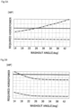
- FIG. 5A is a graph showing efficiencies of the propellers during the hovering of the compound helicopter 10.
- FIG. 5B is a graph showing the efficiencies of the propellers during the high-speed flight (200 kt, ca. 103 m/s) of the compound helicopter 10.
- a horizontal axis represents the washout angles of the propeller blades 53 and 63
- a vertical axis represents required horsepower of rotating each propeller to generate thrust required in each flight state.
- a line passing through square dots represents a relation between the required horsepower of the first propeller 50 and the washout angle ⁇ 1 of the first propeller blade 53.
- a line passing through triangle dots represents a relation between a sum of the required horsepower of the first propeller 50 and the required horsepower of the second propeller 60, and the washout angle ⁇ 2 of the second propeller blade 63.
- a thick line represents a propeller horsepower upper limit (i.e., a value obtained by subtracting required horsepower of rotating the main rotor 40, from a horsepower upper limit of the main driving structure 41).
- the scales of the vertical axes of FIGS. 5A and 5B are not necessarily equal to each other. Moreover, when the compound helicopter 10 moves forward, the main driving structure 41 is air-cooled. Therefore, the propeller horsepower upper limit during the high-speed flight of FIG. 5B is larger than the propeller horsepower upper limit during the hovering of FIG. 5A .
- the first propeller 50 generates the positive thrust regardless of the flight state. Therefore, as shown in FIGS. 5A and 5B , the required horsepower does not significantly change regardless of the washout angle, but the required horsepower of the first propeller 50 decreases as the washout angle ⁇ 1 of the first propeller blade 53 increases. In this case, when the washout angle ⁇ 1 is 40 degrees, the required horsepower of the first propeller 50 becomes minimum. Therefore, a thrust efficiency of the first propeller 50 improves as the washout angle ⁇ 1 increases (for example, as the washout angle ⁇ 1 approaches 40 degrees).
- the direction of the thrust of the second propeller 60 changes in accordance with the speed of the compound helicopter 10.
- the second propeller 60 generates the negative thrust during the hovering and the low-speed flight that is the initial stage of the forward flight, and generates the positive thrust during the high-speed flight. Therefore, as shown in FIGS. 5A and 5B , the required horsepower of the second propeller 60 significantly changes by the washout angle ⁇ 2.
- the tendency of the change in the required horsepower of the second propeller 60 differs between during the hovering of FIG. 5A and during the high-speed flight of FIG. 5B . Therefore, the washout angle ⁇ 2 of the second propeller 60 is set to a value which is smaller than the propeller horsepower upper limit and by which both the required horsepower during the hovering and the required horsepower during the high-speed flight become small.
- the required horsepower of the second propeller 60 decreases as the washout angle ⁇ 2 of the second propeller blade 63 increases. Therefore, as the washout angle ⁇ 2 increases (for example, the washout angle ⁇ 2 approaches 40 degrees), the thrust efficiency of the second propeller 60 improves.
- the upper limit of the washout angle ⁇ 2 is, for example, 26 degrees that is a value at which the sum of the required horsepower of the first propeller 50 and the required horsepower of the second propeller 60 and the propeller horsepower upper limit coincide with each other.
- the lower limit of the washout angle ⁇ 2 is, for example, 18 degrees that is a value at which the sum of the required horsepower of the first propeller 50 and the required horsepower of the second propeller 60 and the propeller horsepower upper limit coincide with each other.
- the washout angle ⁇ 2 is set to, for example, 22 degrees in consideration of a margin.
- the required thrust of the first propeller 50, the required thrust of the second propeller 60, and the direction of the thrust change in accordance with the flight state, such as the hovering, the low-speed flight, or the high-speed flight. Therefore, the specifications of the left propeller and the specifications of the right propeller do not have to be the same as each other, and the propellers most suitable for the compound helicopter can be realized.
- the second propeller 60 generates the negative thrust during the hovering and the low-speed flight that is the initial stage of the forward flight, and generates the positive thrust after the low-speed flight.
- the first propeller 50 generates the positive thrust regardless of the flight state.
- the propeller specifications are set by, for example, adjusting the washout angles of the propeller blades.
- the washout angle ⁇ 2 of the second propeller blade 63 is smaller than the washout angle ⁇ 1 of the first propeller blade 53. With this, if the first propeller blades 53 and the second propeller blades 63 rotate at the same rotational speed and the same negative pitch angle, the negative thrust of the second propeller blade 63 is larger than the negative thrust of the first propeller blade 53.
- first propeller blades 53 and the second propeller blades 63 rotate at the same rotational speed and the same positive pitch angle, i.e., an angle + ⁇
- the first propeller blades 53 generate positive thrust +Fp
- the second propeller blades 63 generate positive thrust +Sp.
- the first propeller blades 53 and the second propeller blades 63 rotate at the same rotational speed and the same negative pitch angle, i.e., an angle - ⁇
- the first propeller blades 53 generate negative thrust -Fm
- the second propeller blades 63 generate negative thrust -Sm.
- the first propeller blade 53 is formed in a shape suitable for the generation of the positive thrust.
- the second propeller blade 63 is formed in a shape which suppresses a decrease in efficiency for the positive thrust and the negative thrust. Therefore, a flight efficiency of the compound helicopter 10 improves.
- the compound helicopter 10 is increased in speed, and the movement of the compound helicopter 10 in the yaw direction can be controlled.
- the most suitable propellers are realized by making the washout angles of the first propeller 50 and the second propeller 60 different from each other among the specifications of the propellers.
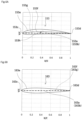
- the blade sectional shapes of a first propeller blade 153 and a second propeller blade 163 are made different from each other.
- a camber of the second propeller blade 163 is smaller than a camber of the first propeller blade 153.
- the camber of the first propeller blade 153 is a difference between a camber line 153f and a chord line 153g.
- the camber line 153f is a center line of a thickness of the sectional shape of the first propeller blade 153
- the chord line 153g is a straight line connecting leading and trailing edges of the first propeller blade 153.
- the camber of the second propeller blade 163 is a difference between a camber line 163f and a chord line 163g.
- the camber line 163f is a center line of a thickness of the sectional shape of the second propeller blade 163, and the chord line 163g is a straight line connecting leading and trailing edges of the second propeller blade 163.
- the first propeller blade 153 is a camber blade whose camber is larger than zero.
- the second propeller blade 163 is a symmetric blade whose camber is zero.
- the propeller blades 153 and 163 are not designed as washout.
- An external form line 153e is a line representing the shape of a section orthogonal to a longitudinal direction of the propeller blade 153
- an external form line 163e is a line representing the shape of a section orthogonal to a longitudinal direction of the propeller blade 163.
- the center line 153f is a line passing through a center between parts of the external form line 153e which parts are located at upper and lower sides of the chord line 153g that is the straight line connecting a leading edge 153c and a trailing edge 153d
- the center line 163f is a line passing through a center between parts of the external form line 163e which parts are located at upper and lower sides of the chord line 163g that is the straight line connecting a leading edge 163c and a trailing edge 163d.
- the center line 153f is located above the chord line 153g, and a camber 153h is larger than zero. In this case, the first propeller blade 153 easily generates the positive thrust because the first propeller blade 153 is curved toward one side from the chord line 153g.
- the center line 163f coincides with the chord line 163g, and the camber is zero.
- the second propeller blade 163 easily generates both the positive thrust and the negative thrust because the second propeller blade 163 has a symmetrical shape with respect to the chord line 163g.
- the flight efficiency of the compound helicopter 10 can be improved.
- the propeller blade 153 may have the washout angle ⁇ 1
- the propeller blade 163 may have the washout angle ⁇ 2.
- the second propeller blade 163 as the symmetric blade and the first propeller blade 153 as the camber blade are designed as washout, and the washout angle ⁇ 2 of the second propeller blade 163 is smaller than the washout angle ⁇ 1 of the first propeller blade 153.
- the shape of the first propeller blade 153 and the shape of the second propeller blade 163 may be the same as each other or may be different from each other.
- the specifications of the propellers may be set such that a planar shape surrounded by a base end portion 153a, a tip portion 153b, the leading edge 153c, and the trailing edge 153d in the first propeller blade 153 and a planar shape surrounded by a base end portion 163a, a tip portion 163b, the leading edge 163c, and the trailing edge 163d in the second propeller blade 163 are made different from each other.
- the rotational frequency of the first propeller 50 and the rotational frequency of the second propeller 60 are the same as each other.
- the rotational frequency of the first propeller 50 and the rotational frequency of the second propeller 60 may be different from each other such that the thrust and the direction of the thrust which correspond to the flight state are realized.
- the first propeller 50 and the first driving structure 51 are attached to the first main wing portion 31, and the second propeller 60 and the second driving structure 61 are attached to the second main wing portion 32.
- the position of the first propeller 50 and the position of the second propeller 60 are not limited to these as long as the first propeller 50 is disposed at one side of the body 20, and the second propeller 60 is disposed at the other side of the body 20.
- the first propeller 50 and the first driving structure 51 may be attached to one side of the body 20, and the second propeller 60 and the second driving structure 61 may be attached to the other side of the body 20.
- the angle of attack of the first propeller blade 53 decreases from the base end portion 53a toward the tip portion 53b, i.e., is designed as washout, but is not limited to this.
- the angle of attack of the second propeller blade 63 decreases from the base end portion 63a toward the tip portion 63b, i.e., is designed as washout, but is not limited to this.
- the angle of attack of each propeller blade may increase from the base end portion toward the tip portion, i.e., is designed as negative washout (wash-in).
- the compound helicopter of the present disclosure is useful as, for example, a compound helicopter whose flight efficiency is improved.
Landscapes
- Engineering & Computer Science (AREA)
- Aviation & Aerospace Engineering (AREA)
- Mechanical Engineering (AREA)
- Physics & Mathematics (AREA)
- Fluid Mechanics (AREA)
- Toys (AREA)
- Chemical & Material Sciences (AREA)
- Combustion & Propulsion (AREA)
Claims (9)
- Hélicoptère combiné (10) comprenant :un corps (20),une première portion formant aile principale (31) s'étendant à partir du corps vers un côté droit, vu dans la direction d'avancement du corps,une deuxième portion formant aile principale (32) s'étendant à partir du corps vers un côté gauche, vu dans la direction d'avancement du corps,un rotor principal (40) disposé sur un côté supérieur du corps,une première hélice (50) disposée au niveau de la première portion formant aile principale et générant une poussée positive lorsque la direction d'avancement est considérée comme positive, etune deuxième hélice (60) disposée au niveau de la deuxième portion formant aile principale et générant une poussée positive et une poussée négative ;ladite première hélice comprenant une première pale d'hélice (53) consistant en une pale d'hélice dont l'axe de rotation s'étend dans une direction parallèle à un axe de l'hélicoptère combiné ; etla deuxième hélice comprenant une deuxième pale d'hélice (63) consistant en une pale d'hélice dont l'axe de rotation s'étend dans une direction parallèle à l'axe de l'hélicoptère combiné ;les caractéristiques techniques de la première hélice (50) sont différentes des caractéristiques techniques de la deuxième hélice (60),caractérisé en ce que les caractéristiques techniques de la première hélice et de la deuxième hélice comprennent au moins l'une des suivantes : l'angle de vrillage (washout angle) (θ) correspondant à un changement concernant l'angle d'attaque depuis l'emplanture (53a, 63a) de chaque pale d'hélice jusqu'au bout de pale (53b, 63b), une forme en coupe de chaque pale d'hélice (53, 63) ou une forme plane de chaque pale d'hélice.
- Hélicoptère combiné selon la revendication 1, dans lequel :la première hélice (50) génère la poussée positive pendant un vol stationnaire et un vol vers l'avant, etla deuxième hélice (60) génère la poussée négative pendant un vol stationnaire et le stade initial du vol vers l'avant et génère la poussée positive après le stade initial du vol vers l'avant.
- Hélicoptère combiné selon la revendication 1, dans lequel :
la poussée négative générée par la deuxième hélice est supérieure à la poussée négative générée par la première hélice dans des conditions où le rotor principal (40) tourne dans le sens inverse des aiguilles d'une montre, vu de dessus, et où la première pale d'hélice et la deuxième pale d'hélice tournent au même angle de pas négatif (-β) et à la même vitesse de rotation. - Hélicoptère combiné selon l'une quelconque des revendications 1 à 3, dans lequel :la formule « Fp - Fm > Sp - Sm » est satisfaite, dans laquellela poussée générée par la première hélice est représentée par +Fp, et la poussée générée par la deuxième hélice est représentée par +Sp dans des conditions où le rotor principal tourne dans le sens inverse des aiguilles d'une montre, vu de dessus, et où la première hélice et la deuxième hélice tournent à la même vitesse de rotation et au même angle de pas positif, c'est-à-dire un angle β, etla poussée générée par la première hélice est représentée par -Fm, et la poussée générée par la deuxième hélice est représentée par -Sm dans des conditions où le rotor principal tourne dans le sens inverse des aiguilles d'une montre, vu de dessus, et où la première hélice et la deuxième hélice tournent à la même vitesse de rotation et au même angle de pas négatif, c'est-à-dire un angle -β.
- Hélicoptère combiné selon la revendication 1, dans lequel :la première pale d'hélice (53) présente un angle de vrillage (θ1) correspondant à un changement concernant l'angle d'attaque depuis l'emplanture (53a) de la première pale d'hélice jusqu'au bout de pale (53b),la deuxième pale d'hélice (63) présente un angle de vrillage (θ2) correspondant à un changement concernant l'angle d'attaque depuis l'emplanture (63a) de la deuxième pale d'hélice jusqu'au bout de pale (63b), etl'angle de vrillage de la deuxième pale d'hélice est inférieur à l'angle de vrillage de la première pale d'hélice.
- Hélicoptère combiné selon la revendication 5, dans lequel l'angle de vrillage (θ1) de la première pale d'hélice (53) est une valeur telle que la puissance requise pour faire tourner la première pale d'hélice afin de générer une poussée pour un vol stationnaire et un vol vers l'avant est minimale.
- Hélicoptère combiné selon la revendication 5, dans lequel :une limite inférieure de l'angle de vrillage (θ2) de la deuxième pale d'hélice (63) est une valeur à laquelle la somme de la puissance requise pour faire tourner la première pale d'hélice (53) pour générer une poussée pour un vol vers l'avant et de la puissance requise pour faire tourner la deuxième pale d'hélice pour générer une poussée pour un vol vers l'avant coïncide avec une limite supérieure de puissance d'hélice, etune limite supérieure de l'angle de vrillage de la deuxième pale d'hélice est une valeur à laquelle la somme de la puissance requise pour faire tourner la première pale d'hélice afin de générer une poussée pour un vol stationnaire et de la puissance requise pour faire tourner la deuxième pale d'hélice afin de générer une poussée pour un vol stationnaire coïncide avec la limite supérieure de puissance de l'hélice.
- Hélicoptère combiné selon l'une quelconque des revendications 1 à 7, dans lequel :
la cambrure de la deuxième pale d'hélice (63) est inférieure à la cambrure (153h) de la première pale d'hélice (53), ladite cambrure étant une différence entre une ligne de cambrure (153f, 163f) et une ligne de corde (153g, 163g), la ligne de cambrure étant une ligne centrale dans l'épaisseur d'une forme en coupe de chaque pale d'hélice, la ligne de corde étant une ligne droite reliant les bords d'attaque et de fuite (153c, 153d ; 163c, 163d) de chaque pale d'hélice. - Hélicoptère combiné (10) selon la revendication 8, dans lequel :la cambrure (153h) de la première pale d'hélice (53) est supérieure à zéro, etla cambrure de la deuxième pale d'hélice (63) est nulle.
Applications Claiming Priority (1)
| Application Number | Priority Date | Filing Date | Title |
|---|---|---|---|
| PCT/JP2021/010133 WO2022190370A1 (fr) | 2021-03-12 | 2021-03-12 | Hélicoptère combiné |
Publications (3)
| Publication Number | Publication Date |
|---|---|
| EP4234397A1 EP4234397A1 (fr) | 2023-08-30 |
| EP4234397A4 EP4234397A4 (fr) | 2024-01-24 |
| EP4234397B1 true EP4234397B1 (fr) | 2025-06-18 |
Family
ID=83227609
Family Applications (1)
| Application Number | Title | Priority Date | Filing Date |
|---|---|---|---|
| EP21930222.1A Active EP4234397B1 (fr) | 2021-03-12 | 2021-03-12 | Hélicoptère combiné |
Country Status (4)
| Country | Link |
|---|---|
| US (1) | US12515788B2 (fr) |
| EP (1) | EP4234397B1 (fr) |
| JP (1) | JP7436748B2 (fr) |
| WO (1) | WO2022190370A1 (fr) |
Families Citing this family (3)
| Publication number | Priority date | Publication date | Assignee | Title |
|---|---|---|---|---|
| WO2022190370A1 (fr) * | 2021-03-12 | 2022-09-15 | 川崎重工業株式会社 | Hélicoptère combiné |
| USD1042225S1 (en) * | 2023-03-02 | 2024-09-17 | Zipline International Inc. | Aerial vehicle |
| CN117227987B (zh) * | 2023-11-14 | 2024-03-12 | 中国空气动力研究与发展中心计算空气动力研究所 | 一种与操纵面一体化设计的单边膨胀尾喷槽 |
Family Cites Families (13)
| Publication number | Priority date | Publication date | Assignee | Title |
|---|---|---|---|---|
| FR2929243B1 (fr) * | 2008-03-25 | 2010-04-23 | Eurocopter France | Helicoptere hybride rapide a grande distance franchissable |
| FR2943620B1 (fr) | 2009-03-27 | 2012-08-17 | Eurocopter France | Procede et dispositif pour optimiser le point de fonctionnement d'helices propulsives disposees de part et d'autre du fuselage d'un giravion |
| FR3006292B1 (fr) * | 2013-05-30 | 2017-01-27 | Eurocopter France | Giravion a voilure tournante muni d'une pluralite d'helices |
| FR3055311B1 (fr) * | 2016-08-30 | 2018-08-17 | Airbus Helicopters | Giravion muni d'une voilure tournante et d'une helice orientable, et procede applique par ce giravion |
| US20190118935A1 (en) * | 2017-10-24 | 2019-04-25 | General Atomics Aeronautical Systems, Inc. | Shape changing aircraft blade |
| FR3077803B1 (fr) * | 2018-02-15 | 2020-07-31 | Airbus Helicopters | Methode d'amelioration d'une pale afin d'augmenter son incidence negative de decrochage |
| FR3077802B1 (fr) * | 2018-02-15 | 2020-09-11 | Airbus Helicopters | Methode de determination d'un cercle initial de bord d'attaque des profils aerodynamiques d'une pale et d'amelioration de la pale afin d'augmenter son incidence negative de decrochage |
| US11008093B2 (en) * | 2018-03-22 | 2021-05-18 | Aurora Flight Sciences Corporation | Systems and methods for reducing the propeller noise |
| FR3080605B1 (fr) * | 2018-04-26 | 2020-05-29 | Airbus Helicopters | Giravion muni d'une voilure tournante et d'au moins deux helices et procede applique par ce giravion |
| CN108750092A (zh) * | 2018-05-21 | 2018-11-06 | 诺技术有限公司 | 一种混合动力复合式无人直升机 |
| US20200180755A1 (en) * | 2018-12-11 | 2020-06-11 | Airbus Helicopters | Hybrid helicopter including inclined propulsion propellers |
| JP7396908B2 (ja) * | 2020-01-23 | 2023-12-12 | 川崎重工業株式会社 | コンパウンドヘリコプタ |
| WO2022190370A1 (fr) * | 2021-03-12 | 2022-09-15 | 川崎重工業株式会社 | Hélicoptère combiné |
-
2021
- 2021-03-12 WO PCT/JP2021/010133 patent/WO2022190370A1/fr not_active Ceased
- 2021-03-12 JP JP2023505054A patent/JP7436748B2/ja active Active
- 2021-03-12 EP EP21930222.1A patent/EP4234397B1/fr active Active
-
2023
- 2023-05-11 US US18/195,943 patent/US12515788B2/en active Active
Also Published As
| Publication number | Publication date |
|---|---|
| US12515788B2 (en) | 2026-01-06 |
| EP4234397A4 (fr) | 2024-01-24 |
| JPWO2022190370A1 (fr) | 2022-09-15 |
| EP4234397A1 (fr) | 2023-08-30 |
| US20240083573A1 (en) | 2024-03-14 |
| JP7436748B2 (ja) | 2024-02-22 |
| WO2022190370A1 (fr) | 2022-09-15 |
Similar Documents
| Publication | Publication Date | Title |
|---|---|---|
| US12515788B2 (en) | Compound helicopter | |
| CN113784890B (zh) | 混合旋翼式飞行器 | |
| US11174016B2 (en) | Compound rotorcraft with propeller | |
| RU2674224C2 (ru) | Выполненный с возможностью вертикального взлета летательный аппарат | |
| US8186629B2 (en) | Method and a device for optimizing the operation of propulsive propellers disposed on either side of a rotorcraft fuselage | |
| JP7488200B2 (ja) | テールシッター | |
| EP3121117A1 (fr) | Système de commande et stratégie pour personne assise à l'arrière | |
| CN116714761A (zh) | 使用旋翼以模拟刚性机翼空气动力学的vtol飞行器 | |
| US20160052618A1 (en) | A transition arrangement for an aircraft | |
| US20200180755A1 (en) | Hybrid helicopter including inclined propulsion propellers | |
| EP3655318B1 (fr) | Véhicule aérien asymétrique | |
| US6845941B2 (en) | Rotary/fixed wing aircraft | |
| EP3621875B1 (fr) | Véhicule aérien | |
| CN114945510A (zh) | 推力换向式飞机 | |
| JP7396908B2 (ja) | コンパウンドヘリコプタ | |
| EP3552960B1 (fr) | Rotor de queue d'hélicoptère | |
| US11858622B2 (en) | Aircraft | |
| US20210163127A1 (en) | Assembly and Method for Helicopter Anti-Torque | |
| WO2016077297A1 (fr) | Commande de lacet à autorité élevée pour véhicule tandem doté de rotors rigides | |
| US11693429B2 (en) | Multi-rotor aircraft and method of controlling same | |
| US11787539B2 (en) | Convertible aircraft system | |
| CN109625259A (zh) | 横列式旋翼螺旋桨直升机 | |
| CN223408121U (zh) | 一种多飞行姿态三旋翼位置无舵飞行器 | |
| JP2009286345A (ja) | 地面効果翼、回転翼、回転翼機、および固定翼機 | |
| CN120922350A (zh) | 电动多旋翼飞行器 |
Legal Events
| Date | Code | Title | Description |
|---|---|---|---|
| STAA | Information on the status of an ep patent application or granted ep patent |
Free format text: STATUS: THE INTERNATIONAL PUBLICATION HAS BEEN MADE |
|
| PUAI | Public reference made under article 153(3) epc to a published international application that has entered the european phase |
Free format text: ORIGINAL CODE: 0009012 |
|
| STAA | Information on the status of an ep patent application or granted ep patent |
Free format text: STATUS: REQUEST FOR EXAMINATION WAS MADE |
|
| 17P | Request for examination filed |
Effective date: 20230512 |
|
| AK | Designated contracting states |
Kind code of ref document: A1 Designated state(s): AL AT BE BG CH CY CZ DE DK EE ES FI FR GB GR HR HU IE IS IT LI LT LU LV MC MK MT NL NO PL PT RO RS SE SI SK SM TR |
|
| REG | Reference to a national code |
Ref country code: DE Ref legal event code: R079 Free format text: PREVIOUS MAIN CLASS: B64C0011180000 Ipc: B64C0027260000 Ref country code: DE Ref legal event code: R079 Ref document number: 602021032643 Country of ref document: DE Free format text: PREVIOUS MAIN CLASS: B64C0011180000 Ipc: B64C0027260000 |
|
| A4 | Supplementary search report drawn up and despatched |
Effective date: 20240102 |
|
| RIC1 | Information provided on ipc code assigned before grant |
Ipc: B64C 11/46 20060101ALI20231219BHEP Ipc: B64C 27/82 20060101ALI20231219BHEP Ipc: B64C 11/30 20060101ALI20231219BHEP Ipc: B64C 11/18 20060101ALI20231219BHEP Ipc: B64C 27/26 20060101AFI20231219BHEP |
|
| DAV | Request for validation of the european patent (deleted) | ||
| DAX | Request for extension of the european patent (deleted) | ||
| STAA | Information on the status of an ep patent application or granted ep patent |
Free format text: STATUS: EXAMINATION IS IN PROGRESS |
|
| 17Q | First examination report despatched |
Effective date: 20240918 |
|
| GRAP | Despatch of communication of intention to grant a patent |
Free format text: ORIGINAL CODE: EPIDOSNIGR1 |
|
| STAA | Information on the status of an ep patent application or granted ep patent |
Free format text: STATUS: GRANT OF PATENT IS INTENDED |
|
| INTG | Intention to grant announced |
Effective date: 20250325 |
|
| GRAS | Grant fee paid |
Free format text: ORIGINAL CODE: EPIDOSNIGR3 |
|
| GRAA | (expected) grant |
Free format text: ORIGINAL CODE: 0009210 |
|
| STAA | Information on the status of an ep patent application or granted ep patent |
Free format text: STATUS: THE PATENT HAS BEEN GRANTED |
|
| AK | Designated contracting states |
Kind code of ref document: B1 Designated state(s): AL AT BE BG CH CY CZ DE DK EE ES FI FR GB GR HR HU IE IS IT LI LT LU LV MC MK MT NL NO PL PT RO RS SE SI SK SM TR |
|
| REG | Reference to a national code |
Ref country code: GB Ref legal event code: FG4D |
|
| REG | Reference to a national code |
Ref country code: CH Ref legal event code: EP |
|
| REG | Reference to a national code |
Ref country code: DE Ref legal event code: R096 Ref document number: 602021032643 Country of ref document: DE |
|
| REG | Reference to a national code |
Ref country code: CH Ref legal event code: EP |
|
| REG | Reference to a national code |
Ref country code: IE Ref legal event code: FG4D |
|
| PG25 | Lapsed in a contracting state [announced via postgrant information from national office to epo] |
Ref country code: FI Free format text: LAPSE BECAUSE OF FAILURE TO SUBMIT A TRANSLATION OF THE DESCRIPTION OR TO PAY THE FEE WITHIN THE PRESCRIBED TIME-LIMIT Effective date: 20250618 |
|
| REG | Reference to a national code |
Ref country code: LT Ref legal event code: MG9D |
|
| PG25 | Lapsed in a contracting state [announced via postgrant information from national office to epo] |
Ref country code: GR Free format text: LAPSE BECAUSE OF FAILURE TO SUBMIT A TRANSLATION OF THE DESCRIPTION OR TO PAY THE FEE WITHIN THE PRESCRIBED TIME-LIMIT Effective date: 20250919 Ref country code: NO Free format text: LAPSE BECAUSE OF FAILURE TO SUBMIT A TRANSLATION OF THE DESCRIPTION OR TO PAY THE FEE WITHIN THE PRESCRIBED TIME-LIMIT Effective date: 20250918 |
|
| PG25 | Lapsed in a contracting state [announced via postgrant information from national office to epo] |
Ref country code: BG Free format text: LAPSE BECAUSE OF FAILURE TO SUBMIT A TRANSLATION OF THE DESCRIPTION OR TO PAY THE FEE WITHIN THE PRESCRIBED TIME-LIMIT Effective date: 20250618 |
|
| PG25 | Lapsed in a contracting state [announced via postgrant information from national office to epo] |
Ref country code: HR Free format text: LAPSE BECAUSE OF FAILURE TO SUBMIT A TRANSLATION OF THE DESCRIPTION OR TO PAY THE FEE WITHIN THE PRESCRIBED TIME-LIMIT Effective date: 20250618 |
|
| PG25 | Lapsed in a contracting state [announced via postgrant information from national office to epo] |
Ref country code: RS Free format text: LAPSE BECAUSE OF FAILURE TO SUBMIT A TRANSLATION OF THE DESCRIPTION OR TO PAY THE FEE WITHIN THE PRESCRIBED TIME-LIMIT Effective date: 20250918 |
|
| REG | Reference to a national code |
Ref country code: NL Ref legal event code: MP Effective date: 20250618 |
|
| PG25 | Lapsed in a contracting state [announced via postgrant information from national office to epo] |
Ref country code: LV Free format text: LAPSE BECAUSE OF FAILURE TO SUBMIT A TRANSLATION OF THE DESCRIPTION OR TO PAY THE FEE WITHIN THE PRESCRIBED TIME-LIMIT Effective date: 20250618 |
|
| PG25 | Lapsed in a contracting state [announced via postgrant information from national office to epo] |
Ref country code: NL Free format text: LAPSE BECAUSE OF FAILURE TO SUBMIT A TRANSLATION OF THE DESCRIPTION OR TO PAY THE FEE WITHIN THE PRESCRIBED TIME-LIMIT Effective date: 20250618 |
|
| PG25 | Lapsed in a contracting state [announced via postgrant information from national office to epo] |
Ref country code: PT Free format text: LAPSE BECAUSE OF FAILURE TO SUBMIT A TRANSLATION OF THE DESCRIPTION OR TO PAY THE FEE WITHIN THE PRESCRIBED TIME-LIMIT Effective date: 20251020 |
|
| REG | Reference to a national code |
Ref country code: AT Ref legal event code: MK05 Ref document number: 1803986 Country of ref document: AT Kind code of ref document: T Effective date: 20250618 |
|
| PG25 | Lapsed in a contracting state [announced via postgrant information from national office to epo] |
Ref country code: IS Free format text: LAPSE BECAUSE OF FAILURE TO SUBMIT A TRANSLATION OF THE DESCRIPTION OR TO PAY THE FEE WITHIN THE PRESCRIBED TIME-LIMIT Effective date: 20251018 |
|
| PG25 | Lapsed in a contracting state [announced via postgrant information from national office to epo] |
Ref country code: AT Free format text: LAPSE BECAUSE OF FAILURE TO SUBMIT A TRANSLATION OF THE DESCRIPTION OR TO PAY THE FEE WITHIN THE PRESCRIBED TIME-LIMIT Effective date: 20250618 Ref country code: SM Free format text: LAPSE BECAUSE OF FAILURE TO SUBMIT A TRANSLATION OF THE DESCRIPTION OR TO PAY THE FEE WITHIN THE PRESCRIBED TIME-LIMIT Effective date: 20250618 |
|
| PG25 | Lapsed in a contracting state [announced via postgrant information from national office to epo] |
Ref country code: CZ Free format text: LAPSE BECAUSE OF FAILURE TO SUBMIT A TRANSLATION OF THE DESCRIPTION OR TO PAY THE FEE WITHIN THE PRESCRIBED TIME-LIMIT Effective date: 20250618 |
|
| PG25 | Lapsed in a contracting state [announced via postgrant information from national office to epo] |
Ref country code: PL Free format text: LAPSE BECAUSE OF FAILURE TO SUBMIT A TRANSLATION OF THE DESCRIPTION OR TO PAY THE FEE WITHIN THE PRESCRIBED TIME-LIMIT Effective date: 20250618 |
|
| PG25 | Lapsed in a contracting state [announced via postgrant information from national office to epo] |
Ref country code: EE Free format text: LAPSE BECAUSE OF FAILURE TO SUBMIT A TRANSLATION OF THE DESCRIPTION OR TO PAY THE FEE WITHIN THE PRESCRIBED TIME-LIMIT Effective date: 20250618 |
|
| PG25 | Lapsed in a contracting state [announced via postgrant information from national office to epo] |
Ref country code: SK Free format text: LAPSE BECAUSE OF FAILURE TO SUBMIT A TRANSLATION OF THE DESCRIPTION OR TO PAY THE FEE WITHIN THE PRESCRIBED TIME-LIMIT Effective date: 20250618 |
|
| PG25 | Lapsed in a contracting state [announced via postgrant information from national office to epo] |
Ref country code: ES Free format text: LAPSE BECAUSE OF FAILURE TO SUBMIT A TRANSLATION OF THE DESCRIPTION OR TO PAY THE FEE WITHIN THE PRESCRIBED TIME-LIMIT Effective date: 20250618 |