EP4234047B1 - Fahrradtrainer mit höheneinstellglied - Google Patents
Fahrradtrainer mit höheneinstellglied Download PDFInfo
- Publication number
- EP4234047B1 EP4234047B1 EP23158508.4A EP23158508A EP4234047B1 EP 4234047 B1 EP4234047 B1 EP 4234047B1 EP 23158508 A EP23158508 A EP 23158508A EP 4234047 B1 EP4234047 B1 EP 4234047B1
- Authority
- EP
- European Patent Office
- Prior art keywords
- bicycle trainer
- supporting frame
- standing portion
- base
- axle
- Prior art date
- Legal status (The legal status is an assumption and is not a legal conclusion. Google has not performed a legal analysis and makes no representation as to the accuracy of the status listed.)
- Active
Links
Images












Classifications
-
- A—HUMAN NECESSITIES
- A63—SPORTS; GAMES; AMUSEMENTS
- A63B—APPARATUS FOR PHYSICAL TRAINING, GYMNASTICS, SWIMMING, CLIMBING, OR FENCING; BALL GAMES; TRAINING EQUIPMENT
- A63B22/00—Exercising apparatus specially adapted for conditioning the cardio-vascular system, for training agility or co-ordination of movements
- A63B22/06—Exercising apparatus specially adapted for conditioning the cardio-vascular system, for training agility or co-ordination of movements with support elements performing a rotating cycling movement, i.e. a closed path movement
- A63B22/0605—Exercising apparatus specially adapted for conditioning the cardio-vascular system, for training agility or co-ordination of movements with support elements performing a rotating cycling movement, i.e. a closed path movement performing a circular movement, e.g. ergometers
-
- A—HUMAN NECESSITIES
- A63—SPORTS; GAMES; AMUSEMENTS
- A63B—APPARATUS FOR PHYSICAL TRAINING, GYMNASTICS, SWIMMING, CLIMBING, OR FENCING; BALL GAMES; TRAINING EQUIPMENT
- A63B21/00—Exercising apparatus for developing or strengthening the muscles or joints of the body by working against a counterforce, with or without measuring devices
- A63B21/00192—Exercising apparatus for developing or strengthening the muscles or joints of the body by working against a counterforce, with or without measuring devices using resistance provided by magnetic means
-
- A—HUMAN NECESSITIES
- A63—SPORTS; GAMES; AMUSEMENTS
- A63B—APPARATUS FOR PHYSICAL TRAINING, GYMNASTICS, SWIMMING, CLIMBING, OR FENCING; BALL GAMES; TRAINING EQUIPMENT
- A63B21/00—Exercising apparatus for developing or strengthening the muscles or joints of the body by working against a counterforce, with or without measuring devices
- A63B21/005—Exercising apparatus for developing or strengthening the muscles or joints of the body by working against a counterforce, with or without measuring devices using electromagnetic or electric force-resisters
- A63B21/0058—Exercising apparatus for developing or strengthening the muscles or joints of the body by working against a counterforce, with or without measuring devices using electromagnetic or electric force-resisters using motors
-
- A—HUMAN NECESSITIES
- A63—SPORTS; GAMES; AMUSEMENTS
- A63B—APPARATUS FOR PHYSICAL TRAINING, GYMNASTICS, SWIMMING, CLIMBING, OR FENCING; BALL GAMES; TRAINING EQUIPMENT
- A63B21/00—Exercising apparatus for developing or strengthening the muscles or joints of the body by working against a counterforce, with or without measuring devices
- A63B21/15—Arrangements for force transmissions
- A63B21/151—Using flexible elements for reciprocating movements, e.g. ropes or chains
- A63B21/154—Using flexible elements for reciprocating movements, e.g. ropes or chains using special pulley-assemblies
-
- A—HUMAN NECESSITIES
- A63—SPORTS; GAMES; AMUSEMENTS
- A63B—APPARATUS FOR PHYSICAL TRAINING, GYMNASTICS, SWIMMING, CLIMBING, OR FENCING; BALL GAMES; TRAINING EQUIPMENT
- A63B21/00—Exercising apparatus for developing or strengthening the muscles or joints of the body by working against a counterforce, with or without measuring devices
- A63B21/22—Resisting devices with rotary bodies
- A63B21/225—Resisting devices with rotary bodies with flywheels
-
- A—HUMAN NECESSITIES
- A63—SPORTS; GAMES; AMUSEMENTS
- A63B—APPARATUS FOR PHYSICAL TRAINING, GYMNASTICS, SWIMMING, CLIMBING, OR FENCING; BALL GAMES; TRAINING EQUIPMENT
- A63B21/00—Exercising apparatus for developing or strengthening the muscles or joints of the body by working against a counterforce, with or without measuring devices
- A63B21/40—Interfaces with the user related to strength training; Details thereof
- A63B21/4027—Specific exercise interfaces
- A63B21/4033—Handles, pedals, bars or platforms
- A63B21/4035—Handles, pedals, bars or platforms for operation by hand
-
- A—HUMAN NECESSITIES
- A63—SPORTS; GAMES; AMUSEMENTS
- A63B—APPARATUS FOR PHYSICAL TRAINING, GYMNASTICS, SWIMMING, CLIMBING, OR FENCING; BALL GAMES; TRAINING EQUIPMENT
- A63B23/00—Exercising apparatus specially adapted for particular parts of the body
- A63B23/035—Exercising apparatus specially adapted for particular parts of the body for limbs, i.e. upper or lower limbs, e.g. simultaneously
- A63B23/04—Exercising apparatus specially adapted for particular parts of the body for limbs, i.e. upper or lower limbs, e.g. simultaneously for lower limbs
-
- A—HUMAN NECESSITIES
- A63—SPORTS; GAMES; AMUSEMENTS
- A63B—APPARATUS FOR PHYSICAL TRAINING, GYMNASTICS, SWIMMING, CLIMBING, OR FENCING; BALL GAMES; TRAINING EQUIPMENT
- A63B24/00—Electric or electronic controls for exercising apparatus of preceding groups; Controlling or monitoring of exercises, sportive games, training or athletic performances
- A63B24/0087—Electric or electronic controls for exercising apparatus of groups A63B21/00 - A63B23/00, e.g. controlling load
-
- A—HUMAN NECESSITIES
- A63—SPORTS; GAMES; AMUSEMENTS
- A63B—APPARATUS FOR PHYSICAL TRAINING, GYMNASTICS, SWIMMING, CLIMBING, OR FENCING; BALL GAMES; TRAINING EQUIPMENT
- A63B69/00—Training appliances or apparatus for special sports
- A63B69/16—Training appliances or apparatus for special sports for cycling, i.e. arrangements on or for real bicycles
-
- A—HUMAN NECESSITIES
- A63—SPORTS; GAMES; AMUSEMENTS
- A63B—APPARATUS FOR PHYSICAL TRAINING, GYMNASTICS, SWIMMING, CLIMBING, OR FENCING; BALL GAMES; TRAINING EQUIPMENT
- A63B22/00—Exercising apparatus specially adapted for conditioning the cardio-vascular system, for training agility or co-ordination of movements
- A63B22/06—Exercising apparatus specially adapted for conditioning the cardio-vascular system, for training agility or co-ordination of movements with support elements performing a rotating cycling movement, i.e. a closed path movement
- A63B22/0605—Exercising apparatus specially adapted for conditioning the cardio-vascular system, for training agility or co-ordination of movements with support elements performing a rotating cycling movement, i.e. a closed path movement performing a circular movement, e.g. ergometers
- A63B2022/0635—Exercising apparatus specially adapted for conditioning the cardio-vascular system, for training agility or co-ordination of movements with support elements performing a rotating cycling movement, i.e. a closed path movement performing a circular movement, e.g. ergometers specially adapted for a particular use
- A63B2022/0658—Exercising apparatus specially adapted for conditioning the cardio-vascular system, for training agility or co-ordination of movements with support elements performing a rotating cycling movement, i.e. a closed path movement performing a circular movement, e.g. ergometers specially adapted for a particular use for cycling with a group of people, e.g. spinning classes
-
- A—HUMAN NECESSITIES
- A63—SPORTS; GAMES; AMUSEMENTS
- A63B—APPARATUS FOR PHYSICAL TRAINING, GYMNASTICS, SWIMMING, CLIMBING, OR FENCING; BALL GAMES; TRAINING EQUIPMENT
- A63B69/00—Training appliances or apparatus for special sports
- A63B69/16—Training appliances or apparatus for special sports for cycling, i.e. arrangements on or for real bicycles
- A63B2069/161—Training appliances or apparatus for special sports for cycling, i.e. arrangements on or for real bicycles supports for the front of the bicycle
- A63B2069/163—Training appliances or apparatus for special sports for cycling, i.e. arrangements on or for real bicycles supports for the front of the bicycle for the front wheel
-
- A—HUMAN NECESSITIES
- A63—SPORTS; GAMES; AMUSEMENTS
- A63B—APPARATUS FOR PHYSICAL TRAINING, GYMNASTICS, SWIMMING, CLIMBING, OR FENCING; BALL GAMES; TRAINING EQUIPMENT
- A63B69/00—Training appliances or apparatus for special sports
- A63B69/16—Training appliances or apparatus for special sports for cycling, i.e. arrangements on or for real bicycles
- A63B2069/164—Training appliances or apparatus for special sports for cycling, i.e. arrangements on or for real bicycles supports for the rear of the bicycle, e.g. for the rear forks
-
- A—HUMAN NECESSITIES
- A63—SPORTS; GAMES; AMUSEMENTS
- A63B—APPARATUS FOR PHYSICAL TRAINING, GYMNASTICS, SWIMMING, CLIMBING, OR FENCING; BALL GAMES; TRAINING EQUIPMENT
- A63B69/00—Training appliances or apparatus for special sports
- A63B69/16—Training appliances or apparatus for special sports for cycling, i.e. arrangements on or for real bicycles
- A63B2069/164—Training appliances or apparatus for special sports for cycling, i.e. arrangements on or for real bicycles supports for the rear of the bicycle, e.g. for the rear forks
- A63B2069/165—Training appliances or apparatus for special sports for cycling, i.e. arrangements on or for real bicycles supports for the rear of the bicycle, e.g. for the rear forks rear wheel hub supports
-
- A—HUMAN NECESSITIES
- A63—SPORTS; GAMES; AMUSEMENTS
- A63B—APPARATUS FOR PHYSICAL TRAINING, GYMNASTICS, SWIMMING, CLIMBING, OR FENCING; BALL GAMES; TRAINING EQUIPMENT
- A63B69/00—Training appliances or apparatus for special sports
- A63B69/16—Training appliances or apparatus for special sports for cycling, i.e. arrangements on or for real bicycles
- A63B2069/166—Training appliances or apparatus for special sports for cycling, i.e. arrangements on or for real bicycles supports for the central frame of the bicycle, e.g. for the crank axle housing, seat tube or horizontal tube
-
- A—HUMAN NECESSITIES
- A63—SPORTS; GAMES; AMUSEMENTS
- A63B—APPARATUS FOR PHYSICAL TRAINING, GYMNASTICS, SWIMMING, CLIMBING, OR FENCING; BALL GAMES; TRAINING EQUIPMENT
- A63B71/00—Games or sports accessories not covered in groups A63B1/00 - A63B69/00
- A63B71/06—Indicating or scoring devices for games or players, or for other sports activities
- A63B71/0619—Displays, user interfaces and indicating devices, specially adapted for sport equipment, e.g. display mounted on treadmills
- A63B2071/065—Visualisation of specific exercise parameters
-
- A—HUMAN NECESSITIES
- A63—SPORTS; GAMES; AMUSEMENTS
- A63B—APPARATUS FOR PHYSICAL TRAINING, GYMNASTICS, SWIMMING, CLIMBING, OR FENCING; BALL GAMES; TRAINING EQUIPMENT
- A63B21/00—Exercising apparatus for developing or strengthening the muscles or joints of the body by working against a counterforce, with or without measuring devices
- A63B21/005—Exercising apparatus for developing or strengthening the muscles or joints of the body by working against a counterforce, with or without measuring devices using electromagnetic or electric force-resisters
- A63B21/0051—Exercising apparatus for developing or strengthening the muscles or joints of the body by working against a counterforce, with or without measuring devices using electromagnetic or electric force-resisters using eddy currents induced in moved elements, e.g. by permanent magnets
- A63B21/0052—Exercising apparatus for developing or strengthening the muscles or joints of the body by working against a counterforce, with or without measuring devices using electromagnetic or electric force-resisters using eddy currents induced in moved elements, e.g. by permanent magnets induced by electromagnets
-
- A—HUMAN NECESSITIES
- A63—SPORTS; GAMES; AMUSEMENTS
- A63B—APPARATUS FOR PHYSICAL TRAINING, GYMNASTICS, SWIMMING, CLIMBING, OR FENCING; BALL GAMES; TRAINING EQUIPMENT
- A63B21/00—Exercising apparatus for developing or strengthening the muscles or joints of the body by working against a counterforce, with or without measuring devices
- A63B21/005—Exercising apparatus for developing or strengthening the muscles or joints of the body by working against a counterforce, with or without measuring devices using electromagnetic or electric force-resisters
- A63B21/0053—Exercising apparatus for developing or strengthening the muscles or joints of the body by working against a counterforce, with or without measuring devices using electromagnetic or electric force-resisters using alternators or dynamos
- A63B21/0054—Exercising apparatus for developing or strengthening the muscles or joints of the body by working against a counterforce, with or without measuring devices using electromagnetic or electric force-resisters using alternators or dynamos for charging a battery
-
- A—HUMAN NECESSITIES
- A63—SPORTS; GAMES; AMUSEMENTS
- A63B—APPARATUS FOR PHYSICAL TRAINING, GYMNASTICS, SWIMMING, CLIMBING, OR FENCING; BALL GAMES; TRAINING EQUIPMENT
- A63B21/00—Exercising apparatus for developing or strengthening the muscles or joints of the body by working against a counterforce, with or without measuring devices
- A63B21/005—Exercising apparatus for developing or strengthening the muscles or joints of the body by working against a counterforce, with or without measuring devices using electromagnetic or electric force-resisters
- A63B21/0053—Exercising apparatus for developing or strengthening the muscles or joints of the body by working against a counterforce, with or without measuring devices using electromagnetic or electric force-resisters using alternators or dynamos
- A63B21/0055—Exercising apparatus for developing or strengthening the muscles or joints of the body by working against a counterforce, with or without measuring devices using electromagnetic or electric force-resisters using alternators or dynamos the produced electric power used as a source for other equipment, e.g. for TVs
-
- A—HUMAN NECESSITIES
- A63—SPORTS; GAMES; AMUSEMENTS
- A63B—APPARATUS FOR PHYSICAL TRAINING, GYMNASTICS, SWIMMING, CLIMBING, OR FENCING; BALL GAMES; TRAINING EQUIPMENT
- A63B21/00—Exercising apparatus for developing or strengthening the muscles or joints of the body by working against a counterforce, with or without measuring devices
- A63B21/005—Exercising apparatus for developing or strengthening the muscles or joints of the body by working against a counterforce, with or without measuring devices using electromagnetic or electric force-resisters
- A63B21/0058—Exercising apparatus for developing or strengthening the muscles or joints of the body by working against a counterforce, with or without measuring devices using electromagnetic or electric force-resisters using motors
- A63B21/0059—Exercising apparatus for developing or strengthening the muscles or joints of the body by working against a counterforce, with or without measuring devices using electromagnetic or electric force-resisters using motors using a frequency controlled AC motor
-
- A—HUMAN NECESSITIES
- A63—SPORTS; GAMES; AMUSEMENTS
- A63B—APPARATUS FOR PHYSICAL TRAINING, GYMNASTICS, SWIMMING, CLIMBING, OR FENCING; BALL GAMES; TRAINING EQUIPMENT
- A63B2225/00—Miscellaneous features of sport apparatus, devices or equipment
- A63B2225/09—Adjustable dimensions
- A63B2225/093—Height
-
- A—HUMAN NECESSITIES
- A63—SPORTS; GAMES; AMUSEMENTS
- A63B—APPARATUS FOR PHYSICAL TRAINING, GYMNASTICS, SWIMMING, CLIMBING, OR FENCING; BALL GAMES; TRAINING EQUIPMENT
- A63B2225/00—Miscellaneous features of sport apparatus, devices or equipment
- A63B2225/50—Wireless data transmission, e.g. by radio transmitters or telemetry
-
- A—HUMAN NECESSITIES
- A63—SPORTS; GAMES; AMUSEMENTS
- A63B—APPARATUS FOR PHYSICAL TRAINING, GYMNASTICS, SWIMMING, CLIMBING, OR FENCING; BALL GAMES; TRAINING EQUIPMENT
- A63B71/00—Games or sports accessories not covered in groups A63B1/00 - A63B69/00
- A63B71/06—Indicating or scoring devices for games or players, or for other sports activities
- A63B71/0619—Displays, user interfaces and indicating devices, specially adapted for sport equipment, e.g. display mounted on treadmills
- A63B71/0622—Visual, audio or audio-visual systems for entertaining, instructing or motivating the user
Definitions
- the present invention relates to a portable and compact exercise apparatus, in particular to a bicycle trainer with a height adjusting member for a user to be able to exercise anywhere and anytime easily.
- the vertical heights of most conventional trainers are not adjustable or cannot be easily adjusted for bicycles with various wheel sizes, such as 26 or 29 inch wheels.
- Patent documents, US9999818 and US10933290 provide a bicycle trainer with a height adjustment bracket (150), as seen in FIG. 1 , which is coupled between the main frame member (128) and the center leg (112).
- the center leg (112) defines a plurality of apertures (152) along its length that are configured to receive a pin (154) that extends through the opposing member apertures and one of the pluralities of apertures (152) in the center leg (112).
- the bicycle trainer is not compact enough and it is hard for the user to apply lifting force through the height adjustment bracket (150) by one hand while aligning the pin (154) with the corresponding apertures of the center leg (112) and height adjustment bracket (150) by the other hand.
- the user's fingers are very close to a sharp angle formed by the height adjustment bracket (150) and the center leg (112) which might cause injury to the user's fingers.
- the present application provides a bicycle trainer according to claim 1, designed to be safer, portable and compact.
- the bicycle trainer has various features including height adjustment, tension adjustment, optional magnetic poles, power charge, and communication, such as with a smart device or tablet, among other features and advantages.
- the bicycle trainer comprises a base having a base portion and a standing portion; at least one leg pivotally mounted on the base; a supporting frame rotationally pivoted on the standing portion of the base around an axle; a cassette module mounted on the supporting frame and having multiple sprockets; a flywheel module mounted on the supporting frame and being coaxial with the cassette module around an axle; and a height adjusting member, comprising the standing portion, the supporting frame and a fixing element, and the fixing element is placed in or between the standing portion and the supporting frame for keeping the supporting frame at a predetermined angle with respect to the standing portion.
- the fixing element is a locating pin
- the standing portion has at least one aligning hole and the supporting frame has multiple locating holes, and wherein the at least one aligning hole and one of the multiple locating holes can receive the locating pin to keep the supporting frame at a predetermined angle with respect to the standing portion.
- the bicycle trainer further comprises a knob at one end of the locating pin.
- the standing portion has one aligning hole at one side of the standing portion and further has another aligning hole at the other side of the standing portion, and wherein the aligning holes and one of the multiple locating holes can receive the locating pin to keep the supporting frame at a predetermined angle with respect to the standing portion.
- the fixing element is a pawl pivoted on the supporting frame, and wherein the standing portion has a ratchet part and the supporting frame has a spring coupled to the pawl, and wherein the pawl can engage with a teeth of the ratchet part to keep the supporting frame at a predetermined angle with respect to the standing portion.
- the bicycle trainer further comprises a handle disposed at or near the top of the bicycle trainer when the bicycle trainer is in a folded mode.
- the bicycle trainer further comprises an electrical power source accommodated in the base and used to power up electrical components in the bicycle trainer.
- the flywheel module further comprises a dual mode motor simulating uphill and downhill cycling circumstance.
- the bicycle trainer comprises a base having a base portion and a standing portion; at least one leg pivotally mounted on the base; a supporting frame rotationally pivoted on the standing portion of the base around a first axle; a cassette module mounted on the supporting frame and having multiple sprockets and a cassette pulley, the cassette module rotates around a second axle; a flywheel module mounted on the supporting frame and having a flywheel pulley, wherein the flywheel module rotates around the first axle; a belt being around the cassette pulley and the flywheel pulley; and a height adjusting member, comprising the standing portion, the supporting frame and a fixing element, and wherein the fixing element is placed in or between the standing portion and the supporting frame for keeping the supporting frame at a predetermined angle with respect to the standing portion.
- the fixing element is a locating pin
- the standing portion has at least one aligning hole and the supporting frame has multiple locating holes, and wherein the aligning hole and one of the multiple locating holes can receive the locating pin to keep the supporting frame at a predetermined angle with respect to the standing portion.
- the bicycle trainer further comprises a knob at one end of the locating pin.
- the standing portion has one aligning hole at one side of the standing portion and further has another aligning hole at the other side of the standing portion, and wherein the aligning holes and one of the multiple locating holes can receive the locating pin to keep the supporting frame at a predetermined angle with respect to the standing portion.
- the fixing element is a pawl pivoted on the supporting frame, and wherein the standing portion has a ratchet part and the supporting frame has a spring coupled to the pawl, and wherein the pawl can engage with a teeth of the ratchet part to keep the supporting frame at a predetermined angle with respect to the standing portion.
- the bicycle trainer further comprises a handle disposed at or near the top of the bicycle trainer when the bicycle trainer is in a folded mode.
- the bicycle trainer further comprises an electrical power source accommodated in the base and used to power up electrical components in the bicycle trainer.
- the flywheel module further comprises a magnetic resistance component simulating uphill cycling circumstance.
- the base is a one-piece base.
- the bicycle trainer further comprises a belt tension arm pivoted around the axle, an idler pulley pivoted on the belt tension arm and a spring, and one end of the spring is connected to one end of the belt tension arm and the other end of the spring is connected to a housing of the supporting frame, and wherein a tension of the belt is automatically increased or decreased in response to an angle formed between the supporting frame and the standing portion.
- the flywheel pulley, the belt tension arm, the supporting frame and the flywheel module are rotationally co-pivoted around the axle.
- the exercise apparatus comprises a base having a base portion and a standing portion; a supporting frame rotationally pivoted on the standing portion of the base around a first axle; a flywheel module pivotally mounted on the supporting frame around a second axle for simulating uphill and/or downhill cycling circumstance; and a height adjusting member comprising the standing portion, the supporting frame and a fixing element, and wherein the fixing element is placed in or between the standing portion and the supporting frame for keeping the supporting frame at a predetermined angle with respect to the standing portion.
- FIG. 2 depicts a perspective front view of the bicycle trainer (100) in the folded mode and FIG. 3 depicts that in the stretched out mode in accordance with the first embodiment of the present invention.
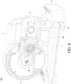
- FIG. 4 depicts a perspective back view of the bicycle trainer (100) in the folded mode and
- FIG. 5 depicts that in the stretched out mode in accordance with the first embodiment of the present invention.
- FIG. 6 depicts a view of a height adjusting member partially enlarged from FIGS. 2 , 3 , 4 and 5 .
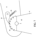
- FIG. 7 depicts a view of another height adjusting member in accordance with the first embodiment of the present invention.
- FIG. 8 depicts a view of yet another height adjusting member in accordance with the first embodiment of the present invention.
- the bicycle trainer (100) comprises a cassette module (1), a flywheel module (2) including a motor and/or a generator, a handle (3), an axle (4), a locating pin (51) with a knob (5), a base (6), two legs (7), a supporting frame (8) and foots (9).
- the base (6) includes a base portion (62) and a standing portion (63).
- the legs (7) are pivotally mounted on the base (6), and the foots (9) are respectively disposed at one end of the legs (7) to increase the friction with the ground.
- the cassette module (1) having multiple sprockets that provides multiple gear ratios to the user.
- the cassette module (1) and the flywheel module (2) are mounted on the supporting frame (8) and are coaxial around an axle (10) including a set of elements for supporting the cassette module (1), the flywheel module (2), bearings and a hub (not shown).
- the supporting frame (8) is rotationally pivoted on the standing portion (63) of the base (6) around the axle (4).
- an electrical power source accommodated in the base (6) such as battery cells (64) or battery packs (64), is used to power up electrical components or devices in the bicycle trainer (100), such as an LCD display, a controlling system that drive the motor with pre-programmed courses or a wireless device.
- the electrical power source can further be used as a power source providing electricity to the user's electronic devices, such as a smart phone, a cellular phone or a speaker.
- the battery cells (64) or battery packs (64) may be charged by the flywheel module (2) as a power generator during cycling exercise.
- the locating pin (51) with the knob (5) is fixed at one of the holes of the supporting frame (8) to keep the supporting frame (8) at low profile.
- the bicycle trainer (100) becomes compact and easy to carry by hand with the handle (3) which is disposed at or near the top of the bicycle trainer (100).
- the user may easily fold out the legs (7) at a desired angle, such as 45, 60, 90 or 135 degrees or any desired degrees with respect to the base (6).
- the user may also easily grab the knob (5) and release the locating pin (51) from the supporting frame (8) and the standing portion (63) of the base (6).
- the user may easily apply a lifting force to the supporting frame (8) with the handle (3) which causes the supporting frame (8) to rotate around the axle (4) at a desired angle.
- the user may easily insert the locating pin (51) into supporting frame (8) and the standing portion (63) of the base (6) so as to keep the supporting frame (8) at a desired height.
- the bicycle trainer (100) is in the stretched out mode after folding out the legs (7) and the supporting frame (8).
- the user may mount his/her own bicycle with the rear wheel been removed to the bicycle trainer (100) through the cassette module (1).
- FIG. 6 It further depicts a height adjusting member of the bicycle trainer (100) which allows the user to use the handle (3) to lift up the supporting frame (8) by means of rotation of the supporting frame (8) around the axle (4).
- the height adjusting member can be used to adjust the angle between the supporting frame (8) and the standing portion (63) of the base (6) so that the height of the axle (10) is varied accordingly.
- the height adjusting member depicted in FIG. 6 comprises the supporting frame (8), the standing portion (63) of the base (6), the locating pin (51) with the knob (5) and a locking unit (optional and not shown).
- the supporting frame (8) has a plurality of locating holes (81) located near the edge of the supporting frame (8).
- the standing portion (63) of the base (6) has two aligning holes (61) located on both sides of the standing portion (63).
- the locating pin (51) extending from the knob (5) such as a star knob, wing knob or ball knob with threaded stud, may clamp the standing portion (63) with a female locking unit, such as a star nut, wing nut or ball nut.
- the locating pin (51) may in turn pass through the aligning hole (61) at one side of the standing portion (63), one of the locating holes (81) and the aligning hole (61) at other side of the standing portion (63) and then be fastened by the female locking unit so as to support the supporting frame (8) at a predetermined height, i.e. to keep the supporting frame (8) at a predetermined angle with respect to the standing portion (63).
- the locating pin (51) may in turn pass through the aligning hole (61) at one side of the standing portion (63) and one of the locating holes (81) and then be fastened to the aligning hole (61) at other side of the standing portion (63).
- the aligning hole (61) at other side of the standing portion (63) are formed with female screws.
- a plurality of aligning holes (61) are respectively arranged on both sides of the standing portion (63), and a locating hole (81) is disposed on the supporting frame (8).
- the locating holes (81) are formed near the edge of the supporting frame (8) and substantially arranged along an arc or a circle centered at the axle (4).
- the locating pin (51) optionally goes through a different one of the locating holes (81)
- the upright or swinging angle of the supporting frame (8) is consequentially changed. That is, the height of the assembly of the cassette module (1), the flywheel module (2) and the supporting frame (8) is varied due to the angle adjustment.
- FIGS. 7 and 8 further depict two variations of the height adjusting member to the bicycle trainer (100) which also allow the user to use the handle (3) to lift up the supporting frame (8) by means of rotation of the supporting frame (8) around the axle (4).
- the height adjusting member depicted in FIG. 7 comprises the supporting frame (8), the standing portion (63) of the base (6), a ratchet part (54), a pawl (55) and a spring (56).
- the pawl (55) can engage with a teeth of the ratchet part (54) to keep the supporting frame (8) at a predetermined angle with respect to the standing portion (63).
- the pawl (55) is optionally engaged with a different teeth or edge of the ratchet part (54) so that the upright or swinging angle of the supporting frame (8) is consequentially changed.
- the height adjusting member depicted in FIG. 8 comprises the supporting frame (8), the standing portion (63) of the base (6), a ratchet part (54), a pawl (55), a clutch (57) and a button (58).
- the ratchet part (54) is fixed or formed on the supporting frame (8) and the pawl (55) is pivoted on the standing portion (63).
- the flywheel module (2) may include a dual mode motor which can simulate uphill and downhill cycling circumstance.
- the user may easily adjust the height of the bicycle trainer (100) to further correspondingly creates a tilted circumstance just like cycling uphill and downhill.
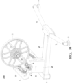
- FIG. 9 depicts a perspective front view of the bicycle trainer (200) in the folded mode and FIG. 10 depicts that in the stretched out mode in accordance with the second embodiment of the present invention.
- FIG. 11 depicts a perspective back view of the bicycle trainer (200) in the folded mode and
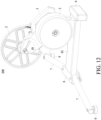
- FIG. 12 depicts that in the stretched out mode in accordance with the second embodiment of the present invention.
- the element of the second embodiment which is the same or similar with that of the first embodiment will be given the same or similar symbol.
- the bicycle trainer (200) comprises a cassette module (1), a flywheel module (2), a handle (3), an axle (4), a knob (5) with a locating pin (not shown), a base (6), legs (7), a supporting frame (8) and foots (9).
- the base (6) includes a base portion (62) and a standing portion (63).
- the legs (7) are pivotally mounted on the base (6) and the foots (9) are respectively disposed at one end of the legs (7) to increase the friction with the ground.
- the cassette module (1) having multiple sprockets that provides multiple gear ratios to the user.
- the cassette module (1) and the flywheel module (2) are mounted on the supporting frame (8), but they respectively rotate around different axles (4, 10).
- the supporting frame (8) is rotationally pivoted around the axle (4) which is same as the first embodiment.
- the height adjusting member depicted in FIGS. 6 , 7 and 8 can be applied to the second embodiment so as to adjust the angle between the supporting frame (8) and the standing portion (63) of the base (6) to correspondingly vary the height of the axle (10).
- the bicycle trainer (200) When the bicycle trainer (200) is in the folded mode, the legs (7) and the supporting frame (8) are kept at low profile.
- the bicycle trainer (200) becomes compact and easy to carry by hand with the handle (3) which is disposed at or near the top of the bicycle trainer (200).
- each leg (7) can be spread at slightly larger than 90 degrees.
- the bicycle trainer (200) is in the stretched out mode after folding out the legs (7) and lifting the supporting frame (8) by the height adjustment member as depicted in FIGS. 6 , 7 and 8 . Then, the user may mount his/her own bicycle with the rear wheel been removed to the bicycle trainer (200) through the cassette module (1).
- FIG. 13 is a front view of the bicycle trainer (200) in the folded mode in accordance with the second embodiment of the present invention.
- the bicycle trainer (200) further comprises a tension adjustment mechanism includes a belt tension arm (13) pivoted around the axle (4), an idler pulley (14) pivoted on the belt tension arm (13) and a spring (15).
- One end of the spring (15) is connected to one end of the belt tension arm (13) and the other end of the spring (15) is connected to the housing of the supporting frame (8).
- the belt tension arm (13) can be clockwise or anticlockwise pulled (or pushed in a different design) by the spring (15) so that the idler pulley (14) exerts force on the belt (19).
- the tension of the belt (19) is increased or decreased in response to the change of the height adjustment of the axle (10) and the angle formed by the supporting frame (8) and the standing portion (63) so as to maintain a proper tension force of the belt (19) automatically.
- it also allows the user to manually adjust the degree of the stretch of the spring (15) through a nut (20).
- the belt (19) is around a cassette pulley (11), the idler pulley (14) and a flywheel pulley (16).
- the two ends of the spring (15) are respectively fixed to the belt tension arm (13) and the supporting frame (8) through a kit set including a hook, a bolt and a nut or other adjustable kits.
- the flywheel pulley (16), the belt tension arm (13), the supporting frame (8) and the flywheel module (2) are rotationally co-pivoted around the axle (4).
- the flywheel module (2) may include a magnetic resistance component which can provide brake force to the user to simulate uphill riding circumstance.
- the magnetic resistance component makes use of electromagnet to provide the user with variable resistance.
- variable resistance With control of the level of electric current flowing through the magnets, such as 2 poles, 4 poles, 6 poles, 12 poles magnets comprising an iron core and a wire wound into a coil, variable resistance is provided. More current flowing through the magnets means a stronger magnetic force, which increases the resistance in the flywheel module (2).
- the user may easily adjust the height of the bicycle trainer (200) to further correspondingly creates a tilted circumstance just like cycling uphill.
- the bicycle trainer (200) may also accommodate an electrical power source, such as battery cells or battery packs in the base (6).
- the electrical power source can use to power up electrical components or devices in the bicycle trainer (200), such as an LCD display, a controlling system that drive the motor with pre-programmed courses or a wireless device.
- the electrical power source can further be used as a power source providing electricity to the user's electronic devices, such as a smart phone, a cellular phone or a speaker.
- the battery cells or battery packs may also be charged by the flywheel module (2) operated in a generating mode during cycling exercise.
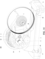
- FIG. 14 depicts a perspective front view of the bicycle trainer (300) in the folded mode and FIG. 15 depicts that in the stretched out mode in accordance with the third embodiment of the present invention.
- FIG. 16 depicts a perspective back view of the bicycle trainer (300) in the folded mode and
- FIG. 17 depicts that in the stretched out mode in accordance with the third embodiment of the present invention.
- the element of the third embodiment which is the same or similar with that of the first or second embodiment will be given the same or similar symbol.
- the bicycle trainer (300) comprises a cassette module (1), a flywheel module (2), a handle (3), an axle (4), a locating pin with a knob (5) (not shown), a base (6), legs (7), a supporting frame (8) and foots (9).
- the base (6) includes a base portion (62) and a standing portion (63).
- the structure of the third embodiment is similar with that of the second embodiment.
- the standing portion (63) of the base (6) of the third embodiment has only one single upright plate to hold the supporting frame (8) instead of two upright plates (or two sides) of the second embodiment as shown in FIGS. 9 , 10 , 11 , 12 and 13 . Accordingly, the same description made to the same element of embodiment 2 is omitted here for simplicity.
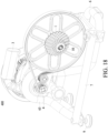
- FIG. 18 depicts a perspective front view of the bicycle trainer (400) in the folded mode and FIG. 19 depicts that in the stretched out mode in accordance with the fourth embodiment of the present invention.
- FIG. 20 depicts a perspective back view of the bicycle trainer (400) in the folded mode and
- FIG. 21 depicts that in the stretched out mode in accordance with the fourth embodiment of the present invention.
- the element of the fourth embodiment which is the same or similar with that of the first, second or third embodiment will be given the same or similar symbol.
- the bicycle trainer (400) comprises a cassette module (1), a flywheel module (2), a handle (3), an axle (4), a knob (5) with a locating pin (not shown), a base (6), legs (7), a supporting frame (8) and foots (9).
- the base (6) of the fourth embodiment is different from that of the first, second or third embodiment, which is mainly made by bended tubes or pipes consisted of metallic or composite material.
- the base (6) is a one-piece base (6) and can also define a base portion (62) and a standing portion (63).
- the one-piece base (6) can have various shapes or sectional profiles including, for example, tubular, square, triangle, oval, diamond, etc.
- the one-piece base (6) may be formed from multiple piece elements which are permanently combined into a one-piece base, for example, by welding or gluing, etc.
- composition and structure of the cassette module (1), the flywheel module (2), a height adjusting member, a tension adjustment mechanism of the fourth embodiment are the same with those of the second embodiment as shown in FIGS. 9 , 10 , 11 , 12 and 13 . Accordingly, the same description made to the same element of embodiment 2 is omitted here for simplicity.
- the handle (3) may be directly above the axle (4), and the cassette module (1) and the axle (10) may be diagonally above the axle (4).
- the handle (3) is directly above the axle (4) both in the stretched out mode and the folded mode; in some examples, the handle (3) is directly above the axle (4) in only one mode of the stretched out mode and the folded mode, for example only in the stretched out mode or only in the folded mode. It is convenient for the user to operate with exertion of force when the handle (3) is directly above the axle (4). The user may use his/her one hand to operate the handle (3).
- the handle (3) is connected to and supported by the supporting frame (8).
- the rotation of the supporting frame (8) around the axle (4) caused by the handle (3) results in that the heights of the cassette module (1) and the axle (10) are varied accordingly, for example, lifted up or lowered down.
- the user may easily adjust the height of the cassette module (1) and the axle (10) and mount his/her own bicycle with the rear wheel been removed to the bicycle trainer (100) through the cassette module (1).
- the user may operate the handle (3) by his/her one hand to adjust the heights of the cassette module (1) and the axle (10), and put the chain of the bicycle (the rear wheel has been removed) on the cassette module (1) by his/her the other hand so as to adjust the height to a desired height.
- the height adjusting member depicted set forth in the embodiments above may be applied not only to a bicycle trainer but also to any exercise apparatus, which, for example, comprises a base having a base portion and a standing portion; a supporting frame rotationally pivoted on the standing portion of the base around a first axle; a flywheel module pivotally mounted on the supporting frame around a second axle for simulating uphill and/or downhill cycling circumstance; and a height adjusting member, comprising the standing portion, the supporting frame and a fixing element, and the fixing element is placed in or between the standing portion and the supporting frame for keeping the supporting frame at a predetermined angle with respect to the standing portion.
Landscapes
- Health & Medical Sciences (AREA)
- General Health & Medical Sciences (AREA)
- Physical Education & Sports Medicine (AREA)
- Orthopedic Medicine & Surgery (AREA)
- Biophysics (AREA)
- Life Sciences & Earth Sciences (AREA)
- Physics & Mathematics (AREA)
- Electromagnetism (AREA)
- Cardiology (AREA)
- Vascular Medicine (AREA)
- Motorcycle And Bicycle Frame (AREA)
- Axle Suspensions And Sidecars For Cycles (AREA)
- Steering Devices For Bicycles And Motorcycles (AREA)
Claims (14)
- Fahrradtrainer (100, 200, 300, 400), umfassend:eine Basis (6), die einen Basisabschnitt (62) aufweist;mindestens einen Schenkel (7), der schwenkbar an der Basis (6) montiert ist;einen Tragrahmen (8);ein Kassettenmodul (1), das auf dem Tragrahmen (8) montiert ist und mehrere Kettenräder hat;ein Schwungradmodul (2), das auf dem Tragrahmen (8) montiert ist; unddadurch gekennzeichnet, dass:
der Tragrahmen (8) drehend auf einem stehenden Abschnitt (63) der Basis (6) um eine Achse (4) geschwenkt wird, und der Fahrradtrainer (100, 200, 300, 400) weiter umfasst:
ein Höhenverstellelement, das den stehenden Abschnitt (63), den Tragrahmen (8) und ein Befestigungselement umfasst, und wobei das Befestigungselement in oder zwischen dem stehenden Abschnitt (63) und dem Tragrahmen (8) platziert ist, um den Tragrahmen (8) in einem vorbestimmten Winkel in Bezug auf den stehenden Abschnitt (63) zu halten. - Fahrradtrainer (100) nach Anspruch 1, wobei das Schwungradmodul (2) koaxial mit dem Kassettenmodul (1) um eine weitere Achse (10) angeordnet ist.
- Fahrradtrainer (200, 300, 400) nach Anspruch 1, wobeidas Kassettenmodul (1) weiter eine Kassettenrolle (11) umfasst, wobei sich das Kassettenmodul (1) um eine weitere Achse (10) dreht;das Schwungradmodul (2) eine Schwungradrolle (16) umfasst, wobei sich das Schwungradmodul (2) um die erste Achse (4) dreht; undder Fahrradtrainer weiter einen Riemen (19) um die Kassettenrolle (11) und die Schwungradrolle (16) aufweist.
- Fahrradtrainer (100, 200, 300, 400) nach einem der vorstehenden Ansprüche, wobei das Fixierungselement ein Positionierstift (51) ist, und wobei der stehenden Abschnitt (63) mindestens ein Ausrichtungsloch (61) aufweist, und der Tragrahmen (8) mehrere Fixierlöcher (81) aufweist, und wobei das mindestens eine Ausrichtungsloch (61) und eines der mehreren Fixierlöcher (81) den Positionierstift (51) aufnehmen können, um den Tragrahmen (8) in einem vorbestimmten Winkel in Bezug auf den stehenden Abschnitt (63) zu halten.
- Fahrradtrainer (100, 200, 300, 400) nach Anspruch 4, wobei der Fahrradtrainer (100, 300) weiter einen Knauf (5) an einem Ende des Positionierstifts (51) umfasst.
- Fahrradtrainer (100, 200, 400) nach Anspruch 4, wobei der stehende Abschnitt (63) ein Ausrichtungsloch (61) an einer Seite des stehenden Abschnitts (63) hat und weiter ein weiteres Ausrichtungsloch (61) an der anderen Seite des stehenden Abschnitts (63) hat, und wobei die Ausrichtungslöcher (61) und eines der mehreren Fixierlöcher (81) den Positionierstift (51) aufnehmen können, um den Tragrahmen (8) in einem vorbestimmten Winkel in Bezug auf den stehenden Abschnitt (63) zu halten.
- Fahrradtrainer (100, 200, 300, 400) nach einem der vorstehenden Ansprüche 1-3, wobei das Befestigungselement eine Sperrklinke (55) ist, die an dem Tragrahmen (8) geschwenkt wird, und wobei der stehende Abschnitt (63) einen Klinkenradteil (54) hat und der Tragrahmen (8) eine Feder (15) hat, die mit der Sperrklinke (55) gekoppelt ist, und wobei die Sperrklinke (55) in eine Verzahnung des Klinkenradteils (54) eingreifen kann, um den Tragrahmen (8) in einem vorbestimmten Winkel in Bezug auf den stehenden Abschnitt (63) zu halten.
- Fahrradtrainer (100, 200, 300, 400) nach einem der vorstehenden Ansprüche, wobei der Fahrradtrainer (100, 200, 300, 400) weiter einen Griff (3) umfasst, der an oder nahe der Oberseite des Fahrradtrainers (100, 300) angeordnet ist, wenn sich der Fahrradtrainer (100, 300) in einem zusammengeklappten Zustand befindet.
- Fahrradtrainer (100, 200, 300, 400) nach einem der vorstehenden Ansprüche, wobei der Fahrradtrainer (100, 200, 300, 400) weiter eine elektrische Leistungsquelle (64) umfasst, die in der Basis (6) aufgenommen ist und zum Einschalten elektrischer Komponenten in dem Fahrradtrainer (100, 300) verwendet wird.
- Fahrradtrainer (100) nach einem der Ansprüche 2 und 4-9, wobei das Schwungradmodul (2) weiter einen Dualmodus-Motor umfasst, der Bergauffahr- und Bergabfahrbedingungen simuliert.
- Fahrradtrainer (100, 200, 300, 400) nach einem der vorstehenden Ansprüche, wobei das Schwungradmodul (2) weiter eine magnetische Widerstandskomponente umfasst, die Bergauffahrbedingungen simuliert.
- Fahrradtrainer (400) nach einem der vorstehenden Ansprüche, wobei die Basis (6) eine einteilige Basis (6) ist.
- Fahrradtrainer (200, 300, 400) nach einem der Ansprüche 3-12, wobei der Fahrradtrainer (200, 300, 400) weiter einen Riemenspannarm (13), der um die erste Achse (4) geschwenkt wird, eine Laufrolle (14), die um den Riemenspannarm (13) geschwenkt wird, und eine Feder (15) umfasst, und ein Ende der Feder (15) mit einem Ende des Riemenspannarms (13) verbunden ist und das andere Ende der Feder (15) mit einem Gehäuse des Tragrahmens (8) verbunden ist, und wobei eine Spannung des Riemens (19) als Reaktion auf einen Winkel, der zwischen dem Tragrahmen (8) und dem stehenden Abschnitt (63) gebildet ist, automatisch erhöht oder verringert wird.
- Fahrradtrainer (200, 300, 400) nach Anspruch 13, wobei die Schwungradrolle (16), der Riemenspannarm (13), der Tragrahmen (8) und das Schwungradmodul (2) gemeinsam drehend um die erste Achse (4) geschwenkt werden.
Applications Claiming Priority (1)
| Application Number | Priority Date | Filing Date | Title |
|---|---|---|---|
| US202263313745P | 2022-02-25 | 2022-02-25 |
Publications (2)
| Publication Number | Publication Date |
|---|---|
| EP4234047A1 EP4234047A1 (de) | 2023-08-30 |
| EP4234047B1 true EP4234047B1 (de) | 2024-11-13 |
Family
ID=85382613
Family Applications (1)
| Application Number | Title | Priority Date | Filing Date |
|---|---|---|---|
| EP23158508.4A Active EP4234047B1 (de) | 2022-02-25 | 2023-02-24 | Fahrradtrainer mit höheneinstellglied |
Country Status (11)
| Country | Link |
|---|---|
| US (1) | US12357895B2 (de) |
| EP (1) | EP4234047B1 (de) |
| JP (2) | JP7585367B2 (de) |
| KR (1) | KR102815330B1 (de) |
| CN (1) | CN116650907A (de) |
| AU (1) | AU2023201124B2 (de) |
| CA (1) | CA3191016C (de) |
| ES (1) | ES3000282T3 (de) |
| HU (1) | HUE069946T2 (de) |
| PL (1) | PL4234047T3 (de) |
| TW (1) | TWI848582B (de) |
Families Citing this family (1)
| Publication number | Priority date | Publication date | Assignee | Title |
|---|---|---|---|---|
| CN117771640A (zh) * | 2024-02-05 | 2024-03-29 | 深圳市维体运动科技有限公司 | 骑行装置及其骑行台 |
Family Cites Families (21)
| Publication number | Priority date | Publication date | Assignee | Title |
|---|---|---|---|---|
| JP3932372B2 (ja) | 2001-02-06 | 2007-06-20 | 美津濃株式会社 | 自転車用トレーニング装置 |
| US7727124B1 (en) | 2008-05-06 | 2010-06-01 | Saris Cycling Group, Inc. | Foldable and camming pivot mount for a resistance unit in a bicycle trainer |
| JP4945536B2 (ja) | 2008-09-29 | 2012-06-06 | 本田技研工業株式会社 | 二輪車シミュレーション装置 |
| AU2010250126A1 (en) | 2009-05-18 | 2011-12-01 | Cordio, LLC | Exercise machine with stationary bicycle and inflatable seat |
| US8147388B2 (en) * | 2010-05-21 | 2012-04-03 | Lemond Fitness, Inc. | Bike trainer |
| US20120322621A1 (en) | 2011-06-20 | 2012-12-20 | Bingham Jr Robert James | Power measurement device for a bike trainer |
| US20130053223A1 (en) * | 2011-08-30 | 2013-02-28 | Liao Lai Shu-Chiung | Training apparatus for a bicycle |
| JP3174536U (ja) | 2011-12-02 | 2012-03-29 | 東庚企業股▲ふん▼有限公司 | 二輪車訓練装置 |
| US9999818B2 (en) * | 2012-08-27 | 2018-06-19 | Wahoo Fitness Llc | Bicycle trainer |
| US10576348B1 (en) * | 2012-08-27 | 2020-03-03 | Wahoo Fitness, LLC | System and method for controlling a bicycle trainer |
| ITVI20130145A1 (it) | 2013-05-30 | 2014-12-01 | Elite Srl | Dispositivo di allenamento per ciclisti |
| KR101487135B1 (ko) | 2014-07-04 | 2015-02-04 | 정필동 | 승마용 운동기구 |
| CN204147474U (zh) | 2014-08-25 | 2015-02-11 | 翰阳开发股份有限公司 | 脚踏车训练器的阻尼装置 |
| CN204522186U (zh) | 2015-04-15 | 2015-08-05 | 张建朋 | 多功能射击飞镖乒乓球台 |
| EP3097956A1 (de) | 2015-05-26 | 2016-11-30 | Icon Health & Fitness, Inc. | Übungsmaschine mit modi für aufrechtes und liegendes radfahren |
| US11260280B2 (en) * | 2016-08-05 | 2022-03-01 | Larry C. Papadopoulos | Bicycle trainer permitting steering and tilting motion |
| CN107648806B (zh) | 2017-09-28 | 2019-11-01 | 浙江恒耀实业有限公司 | 一种脚踏车训练机 |
| US11383126B2 (en) * | 2019-04-02 | 2022-07-12 | Jinhua Unisky Tools Co., Ltd. | Fluid-damped direct-drive bicycle riding platform and use method thereof |
| TWM581923U (zh) | 2019-05-17 | 2019-08-11 | 昌祐科技國際股份有限公司 | External magnetic resistance training device and bicycle training system using same |
| CN212593735U (zh) | 2019-08-29 | 2021-02-26 | 万虎健身有限责任公司 | 可调节的固定式自行车训练装置 |
| ES2854198A1 (es) * | 2020-03-18 | 2021-09-20 | Oreka Training S L | Aparato para entrenamiento de ciclismo |
-
2023
- 2023-02-23 US US18/173,092 patent/US12357895B2/en active Active
- 2023-02-23 KR KR1020230024441A patent/KR102815330B1/ko active Active
- 2023-02-24 TW TW112106879A patent/TWI848582B/zh active
- 2023-02-24 AU AU2023201124A patent/AU2023201124B2/en active Active
- 2023-02-24 HU HUE23158508A patent/HUE069946T2/hu unknown
- 2023-02-24 CN CN202310161453.1A patent/CN116650907A/zh active Pending
- 2023-02-24 ES ES23158508T patent/ES3000282T3/es active Active
- 2023-02-24 JP JP2023027273A patent/JP7585367B2/ja active Active
- 2023-02-24 EP EP23158508.4A patent/EP4234047B1/de active Active
- 2023-02-24 PL PL23158508.4T patent/PL4234047T3/pl unknown
- 2023-02-24 CA CA3191016A patent/CA3191016C/en active Active
-
2024
- 2024-10-08 JP JP2024176502A patent/JP7767547B2/ja active Active
Also Published As
| Publication number | Publication date |
|---|---|
| AU2023201124B2 (en) | 2024-11-21 |
| ES3000282T3 (en) | 2025-02-28 |
| TW202348281A (zh) | 2023-12-16 |
| KR20230129303A (ko) | 2023-09-08 |
| PL4234047T3 (pl) | 2025-03-10 |
| CA3191016A1 (en) | 2023-08-25 |
| US20230271073A1 (en) | 2023-08-31 |
| CA3191016C (en) | 2026-03-17 |
| CN116650907A (zh) | 2023-08-29 |
| EP4234047A1 (de) | 2023-08-30 |
| JP2023124855A (ja) | 2023-09-06 |
| KR102815330B1 (ko) | 2025-05-30 |
| TWI848582B (zh) | 2024-07-11 |
| US12357895B2 (en) | 2025-07-15 |
| JP7585367B2 (ja) | 2024-11-18 |
| JP7767547B2 (ja) | 2025-11-11 |
| HUE069946T2 (hu) | 2025-04-28 |
| AU2023201124A1 (en) | 2023-09-14 |
| JP2024180441A (ja) | 2024-12-26 |
Similar Documents
| Publication | Publication Date | Title |
|---|---|---|
| US5916069A (en) | Rowing exerciser with magnetic resistance | |
| US5733227A (en) | Step exerciser | |
| US6811520B2 (en) | Magnetic control multifunctional exercise apparatus with double cable sheave | |
| US7651443B1 (en) | Exercise apparatus | |
| US7758475B2 (en) | Upper body exercise cycle | |
| US5324060A (en) | Wheelchair cycle apparatus | |
| EP4234047A1 (de) | Fahrradtrainer mit höheneinstellglied | |
| US20060148622A1 (en) | Multi-functional exercising device | |
| US20220362620A1 (en) | Rally fitness equipment | |
| US20120172184A1 (en) | Wheel Type Exercising Device | |
| US20050277521A1 (en) | Rowing exercising apparatus | |
| US20040185988A1 (en) | Exerciser with an adjustable resistance providing member | |
| CN206604073U (zh) | 脚踏车训练机 | |
| CN112587860A (zh) | 划船机的收折机构 | |
| CN210170749U (zh) | 外磁式阻力训练器及使用其的自行车训练系统 | |
| US6196955B1 (en) | Push and pull simulating exerciser | |
| US11491363B2 (en) | Exercise methods and apparatus | |
| CN220588830U (zh) | 一种健身装置 | |
| CN217854391U (zh) | 综合训练设备 | |
| CN101417684A (zh) | 具有自发电功能之健身代步装置 | |
| TWI330237B (en) | Adjusting mechanism | |
| JP3017652U (ja) | 伸展運動具 | |
| CN106080932B (zh) | 一种多功能电动自行车 | |
| CN106178405B (zh) | 一种电子健身车 | |
| CN106184527A (zh) | 一种平衡车 |
Legal Events
| Date | Code | Title | Description |
|---|---|---|---|
| PUAI | Public reference made under article 153(3) epc to a published international application that has entered the european phase |
Free format text: ORIGINAL CODE: 0009012 |
|
| STAA | Information on the status of an ep patent application or granted ep patent |
Free format text: STATUS: THE APPLICATION HAS BEEN PUBLISHED |
|
| AK | Designated contracting states |
Kind code of ref document: A1 Designated state(s): AL AT BE BG CH CY CZ DE DK EE ES FI FR GB GR HR HU IE IS IT LI LT LU LV MC ME MK MT NL NO PL PT RO RS SE SI SK SM TR |
|
| STAA | Information on the status of an ep patent application or granted ep patent |
Free format text: STATUS: REQUEST FOR EXAMINATION WAS MADE |
|
| 17P | Request for examination filed |
Effective date: 20240216 |
|
| RBV | Designated contracting states (corrected) |
Designated state(s): AL AT BE BG CH CY CZ DE DK EE ES FI FR GB GR HR HU IE IS IT LI LT LU LV MC ME MK MT NL NO PL PT RO RS SE SI SK SM TR |
|
| GRAP | Despatch of communication of intention to grant a patent |
Free format text: ORIGINAL CODE: EPIDOSNIGR1 |
|
| STAA | Information on the status of an ep patent application or granted ep patent |
Free format text: STATUS: GRANT OF PATENT IS INTENDED |
|
| INTG | Intention to grant announced |
Effective date: 20240621 |
|
| RIC1 | Information provided on ipc code assigned before grant |
Ipc: A63B 69/16 20060101ALI20240611BHEP Ipc: A63B 1/00 20060101AFI20240611BHEP |
|
| GRAS | Grant fee paid |
Free format text: ORIGINAL CODE: EPIDOSNIGR3 |
|
| GRAA | (expected) grant |
Free format text: ORIGINAL CODE: 0009210 |
|
| STAA | Information on the status of an ep patent application or granted ep patent |
Free format text: STATUS: THE PATENT HAS BEEN GRANTED |
|
| AK | Designated contracting states |
Kind code of ref document: B1 Designated state(s): AL AT BE BG CH CY CZ DE DK EE ES FI FR GB GR HR HU IE IS IT LI LT LU LV MC ME MK MT NL NO PL PT RO RS SE SI SK SM TR |
|
| REG | Reference to a national code |
Ref country code: GB Ref legal event code: FG4D |
|
| REG | Reference to a national code |
Ref country code: CH Ref legal event code: EP |
|
| REG | Reference to a national code |
Ref country code: IE Ref legal event code: FG4D |
|
| REG | Reference to a national code |
Ref country code: DE Ref legal event code: R096 Ref document number: 602023000973 Country of ref document: DE |
|
| REG | Reference to a national code |
Ref country code: NL Ref legal event code: FP |
|
| REG | Reference to a national code |
Ref country code: ES Ref legal event code: FG2A Ref document number: 3000282 Country of ref document: ES Kind code of ref document: T3 Effective date: 20250228 |
|
| REG | Reference to a national code |
Ref country code: LT Ref legal event code: MG9D |
|
| PG25 | Lapsed in a contracting state [announced via postgrant information from national office to epo] |
Ref country code: HR Free format text: LAPSE BECAUSE OF FAILURE TO SUBMIT A TRANSLATION OF THE DESCRIPTION OR TO PAY THE FEE WITHIN THE PRESCRIBED TIME-LIMIT Effective date: 20241113 Ref country code: PT Free format text: LAPSE BECAUSE OF FAILURE TO SUBMIT A TRANSLATION OF THE DESCRIPTION OR TO PAY THE FEE WITHIN THE PRESCRIBED TIME-LIMIT Effective date: 20250313 Ref country code: IS Free format text: LAPSE BECAUSE OF FAILURE TO SUBMIT A TRANSLATION OF THE DESCRIPTION OR TO PAY THE FEE WITHIN THE PRESCRIBED TIME-LIMIT Effective date: 20250313 |
|
| PG25 | Lapsed in a contracting state [announced via postgrant information from national office to epo] |
Ref country code: FI Free format text: LAPSE BECAUSE OF FAILURE TO SUBMIT A TRANSLATION OF THE DESCRIPTION OR TO PAY THE FEE WITHIN THE PRESCRIBED TIME-LIMIT Effective date: 20241113 |
|
| REG | Reference to a national code |
Ref country code: AT Ref legal event code: MK05 Ref document number: 1741230 Country of ref document: AT Kind code of ref document: T Effective date: 20241113 |
|
| PG25 | Lapsed in a contracting state [announced via postgrant information from national office to epo] |
Ref country code: BG Free format text: LAPSE BECAUSE OF FAILURE TO SUBMIT A TRANSLATION OF THE DESCRIPTION OR TO PAY THE FEE WITHIN THE PRESCRIBED TIME-LIMIT Effective date: 20241113 |
|
| PG25 | Lapsed in a contracting state [announced via postgrant information from national office to epo] |
Ref country code: NO Free format text: LAPSE BECAUSE OF FAILURE TO SUBMIT A TRANSLATION OF THE DESCRIPTION OR TO PAY THE FEE WITHIN THE PRESCRIBED TIME-LIMIT Effective date: 20250213 |
|
| PG25 | Lapsed in a contracting state [announced via postgrant information from national office to epo] |
Ref country code: GR Free format text: LAPSE BECAUSE OF FAILURE TO SUBMIT A TRANSLATION OF THE DESCRIPTION OR TO PAY THE FEE WITHIN THE PRESCRIBED TIME-LIMIT Effective date: 20250214 Ref country code: LV Free format text: LAPSE BECAUSE OF FAILURE TO SUBMIT A TRANSLATION OF THE DESCRIPTION OR TO PAY THE FEE WITHIN THE PRESCRIBED TIME-LIMIT Effective date: 20241113 Ref country code: AT Free format text: LAPSE BECAUSE OF FAILURE TO SUBMIT A TRANSLATION OF THE DESCRIPTION OR TO PAY THE FEE WITHIN THE PRESCRIBED TIME-LIMIT Effective date: 20241113 |
|
| REG | Reference to a national code |
Ref country code: HU Ref legal event code: AG4A Ref document number: E069946 Country of ref document: HU |
|
| PG25 | Lapsed in a contracting state [announced via postgrant information from national office to epo] |
Ref country code: RS Free format text: LAPSE BECAUSE OF FAILURE TO SUBMIT A TRANSLATION OF THE DESCRIPTION OR TO PAY THE FEE WITHIN THE PRESCRIBED TIME-LIMIT Effective date: 20250213 |
|
| PG25 | Lapsed in a contracting state [announced via postgrant information from national office to epo] |
Ref country code: SM Free format text: LAPSE BECAUSE OF FAILURE TO SUBMIT A TRANSLATION OF THE DESCRIPTION OR TO PAY THE FEE WITHIN THE PRESCRIBED TIME-LIMIT Effective date: 20241113 |
|
| PG25 | Lapsed in a contracting state [announced via postgrant information from national office to epo] |
Ref country code: DK Free format text: LAPSE BECAUSE OF FAILURE TO SUBMIT A TRANSLATION OF THE DESCRIPTION OR TO PAY THE FEE WITHIN THE PRESCRIBED TIME-LIMIT Effective date: 20241113 |
|
| PG25 | Lapsed in a contracting state [announced via postgrant information from national office to epo] |
Ref country code: EE Free format text: LAPSE BECAUSE OF FAILURE TO SUBMIT A TRANSLATION OF THE DESCRIPTION OR TO PAY THE FEE WITHIN THE PRESCRIBED TIME-LIMIT Effective date: 20241113 |
|
| PG25 | Lapsed in a contracting state [announced via postgrant information from national office to epo] |
Ref country code: RO Free format text: LAPSE BECAUSE OF FAILURE TO SUBMIT A TRANSLATION OF THE DESCRIPTION OR TO PAY THE FEE WITHIN THE PRESCRIBED TIME-LIMIT Effective date: 20241113 |
|
| PG25 | Lapsed in a contracting state [announced via postgrant information from national office to epo] |
Ref country code: SK Free format text: LAPSE BECAUSE OF FAILURE TO SUBMIT A TRANSLATION OF THE DESCRIPTION OR TO PAY THE FEE WITHIN THE PRESCRIBED TIME-LIMIT Effective date: 20241113 |
|
| PG25 | Lapsed in a contracting state [announced via postgrant information from national office to epo] |
Ref country code: CZ Free format text: LAPSE BECAUSE OF FAILURE TO SUBMIT A TRANSLATION OF THE DESCRIPTION OR TO PAY THE FEE WITHIN THE PRESCRIBED TIME-LIMIT Effective date: 20241113 |
|
| REG | Reference to a national code |
Ref country code: DE Ref legal event code: R097 Ref document number: 602023000973 Country of ref document: DE |
|
| PG25 | Lapsed in a contracting state [announced via postgrant information from national office to epo] |
Ref country code: SE Free format text: LAPSE BECAUSE OF FAILURE TO SUBMIT A TRANSLATION OF THE DESCRIPTION OR TO PAY THE FEE WITHIN THE PRESCRIBED TIME-LIMIT Effective date: 20241113 |
|
| PG25 | Lapsed in a contracting state [announced via postgrant information from national office to epo] |
Ref country code: MC Free format text: LAPSE BECAUSE OF FAILURE TO SUBMIT A TRANSLATION OF THE DESCRIPTION OR TO PAY THE FEE WITHIN THE PRESCRIBED TIME-LIMIT Effective date: 20241113 |
|
| PLBE | No opposition filed within time limit |
Free format text: ORIGINAL CODE: 0009261 |
|
| STAA | Information on the status of an ep patent application or granted ep patent |
Free format text: STATUS: NO OPPOSITION FILED WITHIN TIME LIMIT |
|
| PG25 | Lapsed in a contracting state [announced via postgrant information from national office to epo] |
Ref country code: LU Free format text: LAPSE BECAUSE OF NON-PAYMENT OF DUE FEES Effective date: 20250224 |
|
| 26N | No opposition filed |
Effective date: 20250814 |
|
| PG25 | Lapsed in a contracting state [announced via postgrant information from national office to epo] |
Ref country code: IE Free format text: LAPSE BECAUSE OF NON-PAYMENT OF DUE FEES Effective date: 20250224 |
|
| PGFP | Annual fee paid to national office [announced via postgrant information from national office to epo] |
Ref country code: NL Payment date: 20260127 Year of fee payment: 4 |
|
| REG | Reference to a national code |
Ref country code: CH Ref legal event code: U11 Free format text: ST27 STATUS EVENT CODE: U-0-0-U10-U11 (AS PROVIDED BY THE NATIONAL OFFICE) Effective date: 20260301 |
|
| PGFP | Annual fee paid to national office [announced via postgrant information from national office to epo] |
Ref country code: HU Payment date: 20260209 Year of fee payment: 4 |
|
| PGFP | Annual fee paid to national office [announced via postgrant information from national office to epo] |
Ref country code: ES Payment date: 20260302 Year of fee payment: 4 |
|
| PGFP | Annual fee paid to national office [announced via postgrant information from national office to epo] |
Ref country code: DE Payment date: 20260126 Year of fee payment: 4 |
|
| PGFP | Annual fee paid to national office [announced via postgrant information from national office to epo] |
Ref country code: BE Payment date: 20260209 Year of fee payment: 4 Ref country code: IT Payment date: 20260228 Year of fee payment: 4 |
|
| PGFP | Annual fee paid to national office [announced via postgrant information from national office to epo] |
Ref country code: FR Payment date: 20260119 Year of fee payment: 4 |
|
| PGFP | Annual fee paid to national office [announced via postgrant information from national office to epo] |
Ref country code: CH Payment date: 20260301 Year of fee payment: 4 |
|
| PGFP | Annual fee paid to national office [announced via postgrant information from national office to epo] |
Ref country code: PL Payment date: 20260210 Year of fee payment: 4 |