EP4233949B1 - Venturi-vorrichtung zum regulieren des sauerstoffanteils in atemtherapien - Google Patents
Venturi-vorrichtung zum regulieren des sauerstoffanteils in atemtherapien Download PDFInfo
- Publication number
- EP4233949B1 EP4233949B1 EP22158382.6A EP22158382A EP4233949B1 EP 4233949 B1 EP4233949 B1 EP 4233949B1 EP 22158382 A EP22158382 A EP 22158382A EP 4233949 B1 EP4233949 B1 EP 4233949B1
- Authority
- EP
- European Patent Office
- Prior art keywords
- oxygen
- rear member
- main body
- venturi device
- air
- Prior art date
- Legal status (The legal status is an assumption and is not a legal conclusion. Google has not performed a legal analysis and makes no representation as to the accuracy of the status listed.)
- Active
Links
Images



Classifications
-
- A—HUMAN NECESSITIES
- A61—MEDICAL OR VETERINARY SCIENCE; HYGIENE
- A61M—DEVICES FOR INTRODUCING MEDIA INTO, OR ONTO, THE BODY; DEVICES FOR TRANSDUCING BODY MEDIA OR FOR TAKING MEDIA FROM THE BODY; DEVICES FOR PRODUCING OR ENDING SLEEP OR STUPOR
- A61M16/00—Devices for influencing the respiratory system of patients by gas treatment, e.g. ventilators; Tracheal tubes
- A61M16/10—Preparation of respiratory gases or vapours
- A61M16/1005—Preparation of respiratory gases or vapours with O2 features or with parameter measurement
-
- A—HUMAN NECESSITIES
- A61—MEDICAL OR VETERINARY SCIENCE; HYGIENE
- A61M—DEVICES FOR INTRODUCING MEDIA INTO, OR ONTO, THE BODY; DEVICES FOR TRANSDUCING BODY MEDIA OR FOR TAKING MEDIA FROM THE BODY; DEVICES FOR PRODUCING OR ENDING SLEEP OR STUPOR
- A61M16/00—Devices for influencing the respiratory system of patients by gas treatment, e.g. ventilators; Tracheal tubes
- A61M16/10—Preparation of respiratory gases or vapours
- A61M16/12—Preparation of respiratory gases or vapours by mixing different gases
-
- A—HUMAN NECESSITIES
- A61—MEDICAL OR VETERINARY SCIENCE; HYGIENE
- A61M—DEVICES FOR INTRODUCING MEDIA INTO, OR ONTO, THE BODY; DEVICES FOR TRANSDUCING BODY MEDIA OR FOR TAKING MEDIA FROM THE BODY; DEVICES FOR PRODUCING OR ENDING SLEEP OR STUPOR
- A61M16/00—Devices for influencing the respiratory system of patients by gas treatment, e.g. ventilators; Tracheal tubes
- A61M16/10—Preparation of respiratory gases or vapours
- A61M16/12—Preparation of respiratory gases or vapours by mixing different gases
- A61M16/122—Preparation of respiratory gases or vapours by mixing different gases with dilution
- A61M16/125—Diluting primary gas with ambient air
- A61M16/127—Diluting primary gas with ambient air by Venturi effect, i.e. entrainment mixers
-
- A—HUMAN NECESSITIES
- A61—MEDICAL OR VETERINARY SCIENCE; HYGIENE
- A61M—DEVICES FOR INTRODUCING MEDIA INTO, OR ONTO, THE BODY; DEVICES FOR TRANSDUCING BODY MEDIA OR FOR TAKING MEDIA FROM THE BODY; DEVICES FOR PRODUCING OR ENDING SLEEP OR STUPOR
- A61M16/00—Devices for influencing the respiratory system of patients by gas treatment, e.g. ventilators; Tracheal tubes
- A61M16/20—Valves specially adapted to medical respiratory devices
- A61M16/201—Controlled valves
-
- A—HUMAN NECESSITIES
- A61—MEDICAL OR VETERINARY SCIENCE; HYGIENE
- A61M—DEVICES FOR INTRODUCING MEDIA INTO, OR ONTO, THE BODY; DEVICES FOR TRANSDUCING BODY MEDIA OR FOR TAKING MEDIA FROM THE BODY; DEVICES FOR PRODUCING OR ENDING SLEEP OR STUPOR
- A61M16/00—Devices for influencing the respiratory system of patients by gas treatment, e.g. ventilators; Tracheal tubes
- A61M16/0057—Pumps therefor
- A61M16/0078—Breathing bags
-
- A—HUMAN NECESSITIES
- A61—MEDICAL OR VETERINARY SCIENCE; HYGIENE
- A61M—DEVICES FOR INTRODUCING MEDIA INTO, OR ONTO, THE BODY; DEVICES FOR TRANSDUCING BODY MEDIA OR FOR TAKING MEDIA FROM THE BODY; DEVICES FOR PRODUCING OR ENDING SLEEP OR STUPOR
- A61M16/00—Devices for influencing the respiratory system of patients by gas treatment, e.g. ventilators; Tracheal tubes
- A61M16/06—Respiratory or anaesthetic masks
-
- A—HUMAN NECESSITIES
- A61—MEDICAL OR VETERINARY SCIENCE; HYGIENE
- A61M—DEVICES FOR INTRODUCING MEDIA INTO, OR ONTO, THE BODY; DEVICES FOR TRANSDUCING BODY MEDIA OR FOR TAKING MEDIA FROM THE BODY; DEVICES FOR PRODUCING OR ENDING SLEEP OR STUPOR
- A61M16/00—Devices for influencing the respiratory system of patients by gas treatment, e.g. ventilators; Tracheal tubes
- A61M16/08—Bellows; Connecting tubes ; Water traps; Patient circuits
- A61M16/0816—Joints or connectors
- A61M16/0833—T- or Y-type connectors, e.g. Y-piece
-
- A—HUMAN NECESSITIES
- A61—MEDICAL OR VETERINARY SCIENCE; HYGIENE
- A61M—DEVICES FOR INTRODUCING MEDIA INTO, OR ONTO, THE BODY; DEVICES FOR TRANSDUCING BODY MEDIA OR FOR TAKING MEDIA FROM THE BODY; DEVICES FOR PRODUCING OR ENDING SLEEP OR STUPOR
- A61M16/00—Devices for influencing the respiratory system of patients by gas treatment, e.g. ventilators; Tracheal tubes
- A61M16/08—Bellows; Connecting tubes ; Water traps; Patient circuits
- A61M16/0875—Connecting tubes
-
- A—HUMAN NECESSITIES
- A61—MEDICAL OR VETERINARY SCIENCE; HYGIENE
- A61M—DEVICES FOR INTRODUCING MEDIA INTO, OR ONTO, THE BODY; DEVICES FOR TRANSDUCING BODY MEDIA OR FOR TAKING MEDIA FROM THE BODY; DEVICES FOR PRODUCING OR ENDING SLEEP OR STUPOR
- A61M2202/00—Special media to be introduced, removed or treated
- A61M2202/02—Gases
- A61M2202/0208—Oxygen
Definitions
- the present disclosure concerns a venturi device useable for regulating the fraction of oxygen required for treating a patient, i.e. person, suffering from respiratory troubles, such as a person infected by a coronavirus, for example the Covid-19 virus or one of its variants, involving pulmonary troubles, failures or the like, leading to hypoxemia or the like.
- respiratory troubles such as a person infected by a coronavirus, for example the Covid-19 virus or one of its variants, involving pulmonary troubles, failures or the like, leading to hypoxemia or the like.
- respiratory assistance devices also called medical ventilators, respirators or the like, are used for providing the oxygen-containing gas.
- non-invasive ventilation devices such as pneumatically-actuated devices comprising simple components fluidly cooperating together, such as a hollow body including gas inlet(s) and outlet(s), gas reservoir, flexible hose, respiratory interface...
- pneumatically-actuated devices comprising simple components fluidly cooperating together, such as a hollow body including gas inlet(s) and outlet(s), gas reservoir, flexible hose, respiratory interface...
- non-invasive ventilation devices work rather well for providing oxygen or air/oxygen mixtures to numerous patients.
- oxygen source such as an O 2 gas cylinder or a wall O 2 -connector/plug
- air if required, for delivering pure oxygen or an air/O 2 mixture.
- venturi devices comprise a regulation system for selecting the gas that should be delivered, namely pure oxygen or an air/oxygen mixture.
- a regulation system generally comprises two mobile parts that are axially-slidable, i.e. mobile in axial translation, one toward (or away from) the other so that the user can easily select the desired position, namely an open or a closed position, by axially-sliding one of those mobile parts, thereby allowing or prohibiting any mixing of oxygen with air.
- delivering a wrong gas composition can be a serious problem for a patient, when said patient needs to inhale a specific amount of oxygen for treating a given respiratory trouble or condition affecting said patient.
- delivering an air/oxygen mixture in lieu of pure oxygen to a patient may lead to a severe hypoxemia and, in extreme cases, to the death of the patient.
- delivering pure oxygen in lieu of an air/oxygen mixture may lead to hyperoxia that may be detrimental to the patient.
- fluid mixing devices including venturi elements useable for instance for prodiving oxygen mixtures to patients are given by WO-A-2021/216262 , GB-A-805,941 , US-A-9,498,592 and US-A-3,913,607 .
- a goal of the present disclosure is to provide an improved venturi device that overcomes said problem to better control the fraction of oxygen provided to a patient.
- the solution according to the invention relates to a venturi device for delivering oxygen or an air/oxygen mixture (i.e. oxygen-enriched air) comprising :
- venturi device can comprise one or several of the following features:
- the present disclosure also concerns an installation for providing oxygen or an air/oxygen mixture to a patient comprising a gas reservoir, a flexible hose, a respiratory interface and a connecting hollow body, the gas reservoir and the flexible hose being fluidly connected to the connecting hollow body, and the respiratory interface being fluidly connected to the flexible hose, characterized in that a venturi device according to the present disclosure is further fluidly connected to the connecting hollow body for delivering oxygen or the air/oxygen mixture to said connecting hollow body.
- the installation according to the present disclosure can comprise one or several of the following features:
- Such an installation according to the present disclosure can be used for providing oxygen or an air/oxygen mixture to a patient, i.e. person, in need thereof, i.e. a patient suffering from respiratory troubles ou disease, such as a person infected by a coronavirus, for example the Covid-19 virus or one of its variants, involving pulmonary troubles, failures or the like, leading to hypoxemia or the like, wherein the fraction of oxygen used for treating said patient is regulated by the venturi device according to the present disclosure.
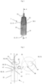
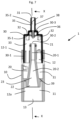
- Figure 1 is a general view of an embodiment of a venturi device 1 according to the present disclosure showing in transparency the two main parts or sub-units cooperating together, namely a main body 10 and a rear member 30, i.e. a gas-providing member or part, forming the venturi device 1 according to the present invention, which are mobile with respect to the other for controlling, i.e. selecting, the type of gas that has to be provided by the venturi device 1, i.e. oxygen or an air/oxygen mixture, as below explained.
- the main body 10 comprises an inner compartment 11 comprising a venturi nozzle 20 co-axially arranged in said inner compartment 11.
- the inner compartment 11 is divided in 2 sub-compartments by an inner wall 39, namely an inlet chamber 12 or upstream chamber, and an outlet chamber 13 or downstream chamber.
- the inner compartment 11 has a circular section, i.e. a cylindrical inner-shape
- the inner wall 39 has a ring-shape.
- the outlet chamber 13 is also shown in the bottom view 61 of Fig. 5 .
- the venturi nozzle 20 is arranged through the inner wall 39 that divides the inner compartment 11. It comprises a nozzle inlet 21 located on the side of the inlet chamber 12 and a nozzle outlet 22 located on the side of the outlet chamber 13, preferably in said outlet chamber 13 as shown in Fig. 6A &B and 7 .
- An inner nozzle channel 20-1, 20-2 is arranged between the nozzle inlet 21 and the nozzle outlet 22 for conveying the gas from the nozzle inlet 21 to the nozzle outlet 22.
- the venturi nozzle 20 comprises two successive channel portions forming the inner nozzle channel 20-1, 20-2 comprising a first channel portion 20-1 comprising the nozzle inlet 21 and having an inner cylindrical shape, and a second channel portion comprising the nozzle outlet 22 and having an inner divergent shape.
- the first channel portion 20-1 fluidly connects the nozzle inlet 21 to the second channel portion 20-2.
- the first channel portion 20-1 can have an inner convergent shape.
- the second channel portion 20-2 is arranged between the first channel portion 20-1 and the nozzle outlet 22. As it comprises an inner divergent shape or profile, its inner diameter gradually increases toward the nozzle outlet 22, as shown in Fig. 6A &B and 7 .
- the gas i.e. O 2 or air/O 2
- the main body 10 has an axially-elongated shape, i.e. along axis (XX) shown in Fig. 7 , in particular a tubular outer shape, e.g. cylindrical outer shape, but other outer shapes are possible.
- the outer diameter of the main body 10 is of about between 25 and 40 mm, and its length is of about between 60 and 110 mm.
- the inlet chamber 12 of the main body 10 is in fluid communication with the mixing chamber 33 of the rear member 30 that constitutes the second main part or sub-unit of the venturi device 1 according to the present disclosure.
- the rear member 30 has a generally cup-like shape, but other shapes are possible. It comprises an oxygen inlet 31 for providing oxygen and one or preferably several air inlets 32 for providing air, and the mixing chamber 33 for mixing therein air with the oxygen and provided by said oxygen inlet 31.
- the oxygen inlet 31 and the air inlets 32, e.g. here four air inlets 32, arranged around the oxygen inlet 31 are better visible in the top view 60 of Fig. 5 .
- the rear member 30 is mobile with respect to the main body 10, upon actuation of a user, between (at least) a closed position (as shown in Fig. 6B), wherein the rear member 30 cooperates directly with the venturi nozzle 20 for providing oxygen to the venturi nozzle 20, in particular to the inner nozzle channel 20-1, 20-2 of the venturi nozzle 20, and an open position (as shown in Fig. 6A ), wherein the rear member 30 cooperates with the venturi nozzle 20 for providing the air/oxygen mixture obtained in the mixing chamber 33 to the inner nozzle channel 20-1, 20-2 of the venturi nozzle 20.
- the inner nozzle channel 20-1, 20-2 of the venturi nozzle 20 is fed with oxygen only, i.e. "pure” oxygen
- the inner nozzle channel 20-1, 20-2 of the venturi nozzle 20 is fed with a mixture of air and oxygen, i.e. an air/oxygen mixture, coming from the mixing chamber 33 of the rear member 30.
- the rear member 30 in the goal of avoiding or limiting accidental motions of those mobile parts, i.e. rear member 30 and main body 10, leading to wrong position settings and to a wrong-gas delivery, for instance oxygen in lieu of an air/O 2 mixture, or vice versa, the rear member 30 is not mobile in translation, but rather according to a helicoidal motion with respect to the main body 10, as shown in Figures 3 & 4 , for allowing the user to manually select and set a desired open or closed position.
- "according to a helicoidal motion” means that the selection or setting of the closed or open position is made by the user when turning, clockwise or counterclockwise (cf. Fig. 3 & 4 ), the rear member 30 with respect to the main body 10 of the venturi device 1 of the invention, or vice versa, thereby obtaining an helicoidal motion of those parts 10, 30, one with respect to the other. In other words, it screws in and out.
- the rear member 30 is helicoidally mobile with respect to the main body 10 when manually-turned clockwise or counterclockwise by a user.
- the main body 10 comprises one or several elongated grooves 40 and the rear member 30 comprises one or several guiding members 50, or vice versa, preferably two elongated grooves 40 cooperating with two guiding members 50, as shown in Fig. 1-6A &B, each guiding member 50 being inserted into one of said elongated grooves 40, thereby cooperating with said elongated grooves 40 for guiding the helicoidal motion of the rear member 30 with respect to the main body 10, while the rear member 30 is actuated by a user, i.e. manually rotated/turned around axis (XX), with respect to the main body (10), or vice versa.
- a user i.e. manually rotated/turned around axis (XX), with respect to the main body (10), or vice versa.
- the two elongated grooves 40 are arranged in the peripheral wall 42 of the main body 10 and are diametrically-opposed, whereas the two guiding members 50 are diametrically-oppositely arranged on the peripheral surface of the rear member 30.
- the elongated grooves 40 constitute guides or paths that guide the guiding members 50, when the venturi device 1 is manually-actuated by the user, i.e. turned clockwise or counterclockwise as shown in Fig. 3 & 4 .
- the elongated grooves 40 are preferably elongated slots 41 traversing the peripheral wall 42 of the main body 10, in particular the inlet chamber 12 of the main body 10, i.e. traversing slots 41 or the like.
- the guiding members 50 comprise or are protrusions 51 arranged on the peripheral outer surface 34 of the rear member 30, preferably the peripheral outer surface 34 of the front portion 30-1 of the rear member 30.
- Each protrusion 51 forms a dent, a pin or any other similar small structure projecting away from the peripheral outer surface 34 of the rear member 30.
- the elongated grooves 40 of the main body 10, in particular the slots 41, comprise a curved linear portion 47, i.e. a linear segment, arranged in the cylindrical peripheral wall 42 of the main body 10, which is terminated by two end lodgings 46A, 46B that correspond to the open (46B) and closed (46A) positions of the venturi device 1.
- the end lodgings 46A, 46B are sized and configured for receiving or lodging the guiding members 50, in particular the protrusions 51.
- the protrusions 51 cooperate with the end lodgings 46A, 46B for setting the venturi device 1 in the open (46B) or closed (46A) positions as illustrated in Figure 2 .
- each elongated groove 40 preferably of each elongated slot 41, is diagonally-arranged in the peripheral wall 42 of the main body 10, namely in the peripheral wall of the inlet chamber 12 of the main body 10 as shown in Fig. 3-5 .
- each end lodging 46A, 46B an abutment 45 as visible in Figure 2 , that is located at a site of junction 48 between of the curved linear portion 47 of the elongated grooves/slots 40, 41 and each end lodgings 46A, 46B.
- said abutments 45 can be little wall structures or similar projecting in each end lodging 46A, 46B.
- the role of those abutments 45 is to block or to retain the protrusions 51 in the end lodgings 46A, 46B for setting the venturi device 1 in the open (46B) or in the closed (46A) positions as illustrated in Figures 2-5 .
- those abutments 45 are safety blocks or the like.
- the venturi device 1 in the closed position with the two protrusions 51 lodged and blocked in the first end lodgings 46A corresponding to said closed position, as illustrated in Fig. 3 (left side), and has to be set in the open position
- the user actuates, namely rotates counterclockwise, for instance the rear member 30 so that the two protrusions 51 are helicoidally guided by the two slots 41, in particular the linear curved portions of the slots 41, until they reach the second end lodgings 46B corresponding to the open position, as illustrated in Fig. 3 (right side).
- the two protrusions 51 are blocked and retained therein by the abutments 45, as better shown in Fig. 2 , that shows an enlarged view of a second end lodging 46B with a protrusion 51 retained therein by an abutment 45.
- the abutments 45 prohibit that the protrusions 51 accidentally get out of the end lodgings 46A, 46B thereby ensuring stable open or closed positions of the venturi device 1.
- the elongated grooves 40 each have a length of about between 20 and 30 mm, and/or a width of about between 3.5 and 5 mm.
- the guiding members 50 e.g. the protrusions 51, have a height of about between 1.5 and 3 mm.
- a front portion 30-1 of the rear member 30 is inserted into at least a part of the inlet chamber 12 of the main body 10.
- said front portion 30-1 of the rear member 30 is externally cylindrical, i.e. tubular, and at least a part 12-1 of the inlet chamber 12 of the main body 10 is internally cylindrical, so that said cylindrical front portion 30-1 of the rear member 30 can be rotate in said cylindrical part 12-1 of the inlet chamber 12 of the main body 10 as shown in Fig. 6A &6B and 7.
- the outer diameter Do of said front portion 30-1 of the rear member 30 is less but approximately equal to the inner diameter Di of the cylindrical part 12-1 of the inlet chamber 12 of the main body 10 so that the helicoidal motion is allowed, i.e. Do ⁇ Di.
- the front portion 30-1 of the rear member 30 delimits at least a part of the mixing chamber 33 used for mixing the oxygen flow and the air flow(s), when required.
- the rear member 30 comprises a hollow tubular portion 30-2 closed at one end by a blind bottom 30-3, i.e. it has a cup-like shape or similar as better shown in Fig. 7 .
- the other end of the tubular portion 30-2 is open toward the inlet chamber 12 of the main body 10.
- the rear member 30 has an outer diameter of about between 20 and 40 mm, and a length of about between 40 and 70 mm.
- the rear member 30 comprises, i.e. is traversed by, an oxygen feeding conduct 35 comprising an outer conduct portion 35-2, i.e. upstream portion, and an inner conduct portion 35-1, i.e. downstream portion, for providing oxygen gas to the venturi device 1.
- the oxygen feeding conduct 35 is axially-arranged (XX axis) through the blind bottom 30-3 of the rear member 30, i.e. it traverses the blind bottom 30-3.
- the outer conduct portion 35-2 of the oxygen feeding conduct 35 comprises the oxygen inlet 31, at its distal free end, and is located outside of the venturi device 1.
- the inner conduct portion 35-1 of the oxygen feeding conduct 35 comprises an oxygen delivery port 36 for providing oxygen located at its free end.
- the oxygen feeding conduct 35 is axially-traversed by a lumen 37 for conveying oxygen gas from the oxygen inlet 31 to the oxygen delivery port 36 thereby providing oxygen coming from an external oxygen source, such as a gas cylinder, a gas line or any other O 2 source.
- an external oxygen source such as a gas cylinder, a gas line or any other O 2 source.
- the outer conduct portion 35-2 of the oxygen feeding conduct 35 also comprises connector means 38, such as a specific outer design, for fluidly connecting an oxygen line thereto as shown in Fig. 8 , preferably an oxygen line fluidly connected to an external oxygen source, such as an oxygen gas cylinder or an oxygen wall-plug fed by a gas network.
- connector means 38 such as a specific outer design, for fluidly connecting an oxygen line thereto as shown in Fig. 8 , preferably an oxygen line fluidly connected to an external oxygen source, such as an oxygen gas cylinder or an oxygen wall-plug fed by a gas network.
- the inner conduct portion 35-1 of the oxygen feeding conduct 35 is arranged so as to axially-project into the mixing chamber 33, whereas the outer conduct portion 35-2 of the oxygen feeding conduct 35 is arranged so as to axially-project outwardly of the rear member, i.e. outside of it.
- the oxygen feeding conduct 35 is in fluid communication, in particular via the lumen 37 of the inner and outer conduct portions 35-1, 35-2, with the mixing chamber 33, when the rear member 30 is in the open position as shown in Fig. 6A and 7 , for mixing air and oxygen, and providing such an O 2 /air mixture to the venturi nozzle 20.
- the oxygen feeding conduct 35 is in fluid communication, in particular via the lumen 37, with the inner nozzle channel 20-1, 20-2 of the venturi nozzle 20, when the rear member 30 is in the closed position as shown in Fig. 6B.
- the proximal free end of the inner conduct portion 35-1 of the oxygen feeding conduct 35 penetrates in the inner nozzle channel 20-1, 20-2 of the venturi nozzle 20, through the nozzle inlet 21, to deliver oxygen directly into the venturi nozzle 20.
- Figure 8 shows an installation 100 for providing oxygen or an air/oxygen mixture to a patient comprising a gas reservoir 101, a flexible hose 103, a respiratory interface 104, a connecting hollow body 102 and a venturi device 1 according to the present disclosure that are in fluid communication.
- the venturi device 1 is fed with oxygen by an oxygen line 105, such as a flexible hose or the like, that conveys an oxygen flow provided by an oxygen source (not shown), such as an O 2 gas cylinder or an O 2 gas conduct.
- an oxygen source not shown
- O 2 gas cylinder or an O 2 gas conduct.
- the venturi device 1 provides a gaseous flow of oxygen or of an air/O 2 mixture to the connecting hollow body 102 that itself feeds the gaseous flow to the gas reservoir 101, such as a flexible bag or the like, and/or to the flexible hose 103, such as a polymer hose, that conveys said gaseous flow to the respiratory interface 104, such as a respiratory mask, i.e. a nasal or facial mask, for delivering said oxygen or air/oxygen mixture to a patient in need thereof.
- the respiratory interface 104 such as a respiratory mask, i.e. a nasal or facial mask
- the gas reservoir constitutes a flexible buffer or the like having an inner volume of between about 1 and 50 L (L in water equivalent), for instance of about 30 L.
Landscapes
- Health & Medical Sciences (AREA)
- Emergency Medicine (AREA)
- Pulmonology (AREA)
- Engineering & Computer Science (AREA)
- Anesthesiology (AREA)
- Biomedical Technology (AREA)
- Heart & Thoracic Surgery (AREA)
- Hematology (AREA)
- Life Sciences & Earth Sciences (AREA)
- Animal Behavior & Ethology (AREA)
- General Health & Medical Sciences (AREA)
- Public Health (AREA)
- Veterinary Medicine (AREA)
- Respiratory Apparatuses And Protective Means (AREA)
Claims (15)
- Venturi-Vorrichtung (1) zum Zuführen von Sauerstoff oder einem Luft/Sauerstoff-Gemisch, umfassend:- einen Hauptkörper (10), der eine innere Kammer (11) und eine in der inneren Kammer (11) angeordnete Venturi-Düse (20) umfasst,- ein hinteres Glied (30), das einen Sauerstoffeinlass (31) zum Bereitstellen von Sauerstoff und mindestens einen Lufteinlass (32) zum Bereitstellen von Luft umfasst, sowie eine Mischkammer (33) zum Mischen von Sauerstoff und Luft darin, die durch den Sauerstoffeinlass (31) und den mindestens einen Lufteinlass (32) bereitgestellt worden sind, wobei das hintere Glied (30) bezüglich des Hauptkörpers (10) zwischen mindestens:dadurch gekennzeichnet, dass das hintere Glied (30) gemäß einer spiralförmigen Bewegung bezüglich des Hauptkörpers (10) beweglich ist, damit ein Benutzer eine gewünschte offene oder geschlossene Position manuell auswählen kann.o einer geschlossenen Position, in der das hintere Glied (30) der Venturi-Düse (20) Sauerstoff zuführt, undo einer offenen Position beweglich ist, in der das hintere Glied (30) der Venturi-Düse (20) ein Luft/Sauerstoff-Gemisch bereitstellt, wobei das Luft/Sauerstoff-Gemisch in der Mischkammer (33) erhalten wird,
- Venturi-Vorrichtung nach Anspruch 1, dadurch gekennzeichnet, dass der Hauptkörper (10) mindestens eine längliche Nut (40) umfasst und das hintere Glied (30) mindestens ein Führungsglied (50) umfasst, oder umgekehrt, wobei das mindestens eine Führungsglied (50) in die mindestens eine längliche Nut (40) eingeführt ist, um mit der mindestens einen länglichen Nut (40) zusammenzuwirken, um die Bewegung des hinteren Glieds (30) bezüglich des Hauptkörpers (10) zu führen, während das hintere Glied (30) von einem Benutzer betätigt wird.
- Venturi-Vorrichtung nach Anspruch 2, dadurch gekennzeichnet, dass der Grundkörper (10) mindestens zwei längliche Nuten (40) umfasst und das hintere Glied (30) mindestens zwei Führungsglieder (50) umfasst, oder umgekehrt.
- Venturi-Vorrichtung nach Anspruch 1, dadurch gekennzeichnet, dass die innere Kammer (11) des Hauptkörpers (10) eine Einlasskammer (12) und einen Gasauslass (13) umfasst, wobei die Einlasskammer (12) des Hauptkörpers (10) mit der Mischkammer (33) des hinteren Glieds (30) in Fluidverbindung steht und ein vorderer Abschnitt (30-1) des hinteren Glieds (30) in mindestens einen Teil (12-1) der Einlasskammer (12) des Hauptkörpers (10) eingeführt ist.
- Venturi-Vorrichtung nach einem der Ansprüche 2 oder 3, dadurch gekennzeichnet, dass:- die länglichen Nuten (40) Schlitze (41) sind, die in der Umfangswand (42) des Hauptkörpers (10) angeordnet sind, und- die Führungsglieder (50) Vorsprünge (51) sind oder umfassen, die an der Außenfläche des hinteren Glieds (30) angeordnet sind.
- Venturi-Vorrichtung nach Anspruch 2, 3 oder 5, dadurch gekennzeichnet, dass jede längliche Nut (40), insbesondere jeder Schlitz (41), einen gekrümmten linearen Abschnitt (47) umfasst, der durch zwei Endaufnahmen (46A, 46B) abgeschlossen ist, die jeweils zur Aufnahme eines Führungsglieds (50) in der offenen oder geschlossenen Position ausgestaltet sind.
- Venturi-Vorrichtung nach Anspruch 6, dadurch gekennzeichnet, dass der gekrümmte lineare Abschnitt (47) jeder länglichen Nut (40) diagonal in der Umfangswand (42) des Hauptkörpers (10) angeordnet ist.
- Venturi-Vorrichtung nach Anspruch 6, dadurch gekennzeichnet, dass jede Endaufnahme (46A, 46B) einen Anschlag (45) umfasst.
- Venturi-Vorrichtung nach Anspruch 1, dadurch gekennzeichnet, dass das hintere Glied (30) ein inneres Leitelement (35) umfasst, das einen proximalen Abschnitt (35-1) umfasst, der eine Sauerstoffzufuhröffnung (36) umfasst und in die Mischkammer (33) des hinteren Glieds (30) ragt.
- Venturi-Vorrichtung nach Anspruch 9, dadurch gekennzeichnet, dass der proximale Abschnitt (35-1) des inneren Leitelements (35) des hinteren Glieds (30) in der geschlossenen Position direkt mit dem inneren Düsenkanal (20-1, 20-2) der Venturi-Düse (20) fluidverbunden ist, um dieser Sauerstoff zuzuführen.
- Venturi-Vorrichtung nach Anspruch 9, dadurch gekennzeichnet, dass der proximale Abschnitt (35-1) des inneren Leitelements (35) des hinteren Glieds (30) in der offenen Position in die Mischkammer (33) des hinteren Glieds (30) mündet, um dort Sauerstoff bereitzustellen und ein Luft/Sauerstoff-Gemisch zu erhalten, das anschließend dem inneren Düsenkanal (20-1, 20-2) der Venturi-Düse (20) zugeführt wird.
- Venturi-Vorrichtung nach einem der vorhergehenden Ansprüche, dadurch gekennzeichnet, dass die Führungsglieder (50) und die länglichen Nuten (40) so ausgestaltet sind, dass jedes Führungsglied (50) in eine entsprechende längliche Nut (40) einfährt, wenn das hintere Glied (30) von einem Benutzer im Uhrzeigersinn oder entgegen dem Uhrzeigersinn bezüglich des Hauptkörpers (10) betätigt wird, oder umgekehrt.
- Venturi-Vorrichtung nach Ansprüchen 6 und 8, dadurch gekennzeichnet, dass die Anschläge (45) dazu ausgestaltet sind, die Führungsglieder (50) in der offenen oder der geschlossenen Position in den Endaufnahmen (46A, 46B) zu halten.
- Anlage (100) zum Bereitstellen von Sauerstoff oder einem Luft/Sauerstoff-Gemisch für einen Patienten, die ein Gasreservoir (101), einen flexiblen Schlauch (103), eine Atemschnittstelle (104) und einen Verbindungshohlkörper (102) umfasst, wobei das Gasreservoir (101) und der flexible Schlauch (103) mit dem Verbindungshohlkörper (102) fluidverbunden sind, und wobei die Atemschnittstelle (104) mit dem flexiblen Schlauch (103) fluidverbunden ist, dadurch gekennzeichnet, dass eine Venturi-Vorrichtung (1) nach einem der vorhergehenden Ansprüche ferner mit dem Verbindungshohlkörper (102) fluidverbunden ist, um dem Verbindungshohlkörper (102) Sauerstoff oder das Luft/Sauerstoff-Gemisch zuzuführen.
- Anlage (100) nach Anspruch 14, dadurch gekennzeichnet, dass eine Sauerstoffleitung (105) mit der Venturi-Vorrichtung (1) fluidverbunden ist, um dieser Sauerstoff zuzuführen.
Priority Applications (4)
| Application Number | Priority Date | Filing Date | Title |
|---|---|---|---|
| EP22158382.6A EP4233949B1 (de) | 2022-02-24 | 2022-02-24 | Venturi-vorrichtung zum regulieren des sauerstoffanteils in atemtherapien |
| ES22158382T ES3031248T3 (en) | 2022-02-24 | 2022-02-24 | Venturi device for regulating the oxygen fraction in respiratory therapies |
| CA3188317A CA3188317A1 (en) | 2022-02-24 | 2023-02-02 | Venturi device for regulating the oxygen fraction in respiratory therapies |
| US18/113,390 US20230263987A1 (en) | 2022-02-24 | 2023-02-23 | Venturi device for regulating the oxygen fraction in respiratory therapies |
Applications Claiming Priority (1)
| Application Number | Priority Date | Filing Date | Title |
|---|---|---|---|
| EP22158382.6A EP4233949B1 (de) | 2022-02-24 | 2022-02-24 | Venturi-vorrichtung zum regulieren des sauerstoffanteils in atemtherapien |
Publications (2)
| Publication Number | Publication Date |
|---|---|
| EP4233949A1 EP4233949A1 (de) | 2023-08-30 |
| EP4233949B1 true EP4233949B1 (de) | 2025-04-23 |
Family
ID=80448304
Family Applications (1)
| Application Number | Title | Priority Date | Filing Date |
|---|---|---|---|
| EP22158382.6A Active EP4233949B1 (de) | 2022-02-24 | 2022-02-24 | Venturi-vorrichtung zum regulieren des sauerstoffanteils in atemtherapien |
Country Status (4)
| Country | Link |
|---|---|
| US (1) | US20230263987A1 (de) |
| EP (1) | EP4233949B1 (de) |
| CA (1) | CA3188317A1 (de) |
| ES (1) | ES3031248T3 (de) |
Family Cites Families (5)
| Publication number | Priority date | Publication date | Assignee | Title |
|---|---|---|---|---|
| GB805941A (en) * | 1955-12-01 | 1958-12-17 | George William Higgs | Improvements in or relating to apparatus for maintaining a controlled atmosphere in infant incubators, oxygen tents and the like |
| US3913607A (en) * | 1974-05-07 | 1975-10-21 | Hudson Oxygen Therapy Sales Co | Oxygen dilution apparatus |
| ITMI20060158U1 (it) | 2006-05-04 | 2007-11-05 | Starmed S P A | Apparecchiatura per la somministrazione di ossigeno o di aria addizionata da ossigeno,per terapie respiratorie. |
| EP2806931B1 (de) * | 2012-01-23 | 2019-04-10 | AEON Research and Technology, LLC | Modulares pulmonales behandlungssystem |
| WO2021216262A1 (en) * | 2020-04-24 | 2021-10-28 | California Institute Of Technology | Fluid blending devices |
-
2022
- 2022-02-24 EP EP22158382.6A patent/EP4233949B1/de active Active
- 2022-02-24 ES ES22158382T patent/ES3031248T3/es active Active
-
2023
- 2023-02-02 CA CA3188317A patent/CA3188317A1/en active Pending
- 2023-02-23 US US18/113,390 patent/US20230263987A1/en active Pending
Also Published As
| Publication number | Publication date |
|---|---|
| EP4233949A1 (de) | 2023-08-30 |
| ES3031248T3 (en) | 2025-07-07 |
| CA3188317A1 (en) | 2023-08-24 |
| US20230263987A1 (en) | 2023-08-24 |
Similar Documents
| Publication | Publication Date | Title |
|---|---|---|
| US8893720B2 (en) | Inhalation apparatus | |
| US3906996A (en) | Breathing therapy aid | |
| EP0768095B1 (de) | Trachealtubus und Vorrichtung für Beatmungssysteme | |
| US20200360641A1 (en) | Modular pulmonary treatment system | |
| CN101663063B (zh) | 气流逆转元件 | |
| US9289568B2 (en) | Gas delivery venturi | |
| US11679244B2 (en) | Apparatus and method for producing an enriched medical suspension of carbon dioxide | |
| US7204248B2 (en) | Fiberoptic nebulizer | |
| EP3624882B1 (de) | Verstellbarer umgebungsluftsauerstoffmischer | |
| CN101365510A (zh) | 具有辅助混合气体出口的气体混合器 | |
| EP3320941A1 (de) | System zur künstlichen beatmung | |
| US20200038618A1 (en) | Breathing Assistance Device with Nebulizer | |
| US4098290A (en) | Miniature intermittent positive pressure breathing valve | |
| EP4233949A1 (de) | Venturi-vorrichtung zum regulieren des sauerstoffanteils in atemtherapien | |
| US12485248B2 (en) | Gas delivery venturi devices | |
| US9511202B1 (en) | Breathing assistance device with nebulizer | |
| US11793958B2 (en) | Needle based precision venturi flow-generator for positive pressure ventilation | |
| US10441739B1 (en) | Multi-functional device having an interchangeable option for a spring-loaded valve for delivering inhaling medical gas and/or nebulized medicine to a spontaneously breathing patient | |
| RU2477152C2 (ru) | Дыхательный аппарат и способ эксплуатации дыхательного аппарата | |
| EP4338775B1 (de) | Manueller künstlicher beatmungsbeutel mit venturi-vorrichtung | |
| EP3110489A1 (de) | Vorrichtung zur verabreichung eines luft-/gasgemischs für die atemtherapie | |
| KR102670538B1 (ko) | 심폐소생술 전용 산소공급 장치 | |
| CN119072342A (zh) | 呼吸回路 | |
| US12377251B2 (en) | Apparatus and method for producing an enriched medical suspension of carbon dioxide | |
| CN223542268U (zh) | 鼻插管组件 |
Legal Events
| Date | Code | Title | Description |
|---|---|---|---|
| PUAI | Public reference made under article 153(3) epc to a published international application that has entered the european phase |
Free format text: ORIGINAL CODE: 0009012 |
|
| STAA | Information on the status of an ep patent application or granted ep patent |
Free format text: STATUS: THE APPLICATION HAS BEEN PUBLISHED |
|
| AK | Designated contracting states |
Kind code of ref document: A1 Designated state(s): AL AT BE BG CH CY CZ DE DK EE ES FI FR GB GR HR HU IE IS IT LI LT LU LV MC MK MT NL NO PL PT RO RS SE SI SK SM TR |
|
| STAA | Information on the status of an ep patent application or granted ep patent |
Free format text: STATUS: REQUEST FOR EXAMINATION WAS MADE |
|
| 17P | Request for examination filed |
Effective date: 20240229 |
|
| RBV | Designated contracting states (corrected) |
Designated state(s): AL AT BE BG CH CY CZ DE DK EE ES FI FR GB GR HR HU IE IS IT LI LT LU LV MC MK MT NL NO PL PT RO RS SE SI SK SM TR |
|
| RAP3 | Party data changed (applicant data changed or rights of an application transferred) |
Owner name: AIR LIQUIDE MEDICAL SYSTEMS S.R.L. Owner name: AIR LIQUIDE MEDICAL SYSTEMS |
|
| GRAP | Despatch of communication of intention to grant a patent |
Free format text: ORIGINAL CODE: EPIDOSNIGR1 |
|
| STAA | Information on the status of an ep patent application or granted ep patent |
Free format text: STATUS: GRANT OF PATENT IS INTENDED |
|
| RIC1 | Information provided on ipc code assigned before grant |
Ipc: A61M 16/00 20060101ALN20241128BHEP Ipc: A61M 16/06 20060101ALN20241128BHEP Ipc: A61M 16/08 20060101ALN20241128BHEP Ipc: A61M 16/12 20060101ALI20241128BHEP Ipc: A61M 16/10 20060101ALI20241128BHEP Ipc: A61M 16/20 20060101ALI20241128BHEP Ipc: A61M 11/06 20060101AFI20241128BHEP |
|
| INTG | Intention to grant announced |
Effective date: 20241206 |
|
| GRAS | Grant fee paid |
Free format text: ORIGINAL CODE: EPIDOSNIGR3 |
|
| GRAA | (expected) grant |
Free format text: ORIGINAL CODE: 0009210 |
|
| STAA | Information on the status of an ep patent application or granted ep patent |
Free format text: STATUS: THE PATENT HAS BEEN GRANTED |
|
| AK | Designated contracting states |
Kind code of ref document: B1 Designated state(s): AL AT BE BG CH CY CZ DE DK EE ES FI FR GB GR HR HU IE IS IT LI LT LU LV MC MK MT NL NO PL PT RO RS SE SI SK SM TR |
|
| REG | Reference to a national code |
Ref country code: GB Ref legal event code: FG4D |
|
| REG | Reference to a national code |
Ref country code: CH Ref legal event code: EP |
|
| REG | Reference to a national code |
Ref country code: DE Ref legal event code: R096 Ref document number: 602022013376 Country of ref document: DE |
|
| REG | Reference to a national code |
Ref country code: IE Ref legal event code: FG4D |
|
| REG | Reference to a national code |
Ref country code: ES Ref legal event code: FG2A Ref document number: 3031248 Country of ref document: ES Kind code of ref document: T3 Effective date: 20250707 |
|
| REG | Reference to a national code |
Ref country code: NL Ref legal event code: MP Effective date: 20250423 |
|
| PG25 | Lapsed in a contracting state [announced via postgrant information from national office to epo] |
Ref country code: NL Free format text: LAPSE BECAUSE OF FAILURE TO SUBMIT A TRANSLATION OF THE DESCRIPTION OR TO PAY THE FEE WITHIN THE PRESCRIBED TIME-LIMIT Effective date: 20250423 |
|
| REG | Reference to a national code |
Ref country code: AT Ref legal event code: MK05 Ref document number: 1787198 Country of ref document: AT Kind code of ref document: T Effective date: 20250423 |
|
| PG25 | Lapsed in a contracting state [announced via postgrant information from national office to epo] |
Ref country code: FI Free format text: LAPSE BECAUSE OF FAILURE TO SUBMIT A TRANSLATION OF THE DESCRIPTION OR TO PAY THE FEE WITHIN THE PRESCRIBED TIME-LIMIT Effective date: 20250423 Ref country code: PT Free format text: LAPSE BECAUSE OF FAILURE TO SUBMIT A TRANSLATION OF THE DESCRIPTION OR TO PAY THE FEE WITHIN THE PRESCRIBED TIME-LIMIT Effective date: 20250825 |
|
| REG | Reference to a national code |
Ref country code: LT Ref legal event code: MG9D |
|
| PG25 | Lapsed in a contracting state [announced via postgrant information from national office to epo] |
Ref country code: NO Free format text: LAPSE BECAUSE OF FAILURE TO SUBMIT A TRANSLATION OF THE DESCRIPTION OR TO PAY THE FEE WITHIN THE PRESCRIBED TIME-LIMIT Effective date: 20250723 Ref country code: GR Free format text: LAPSE BECAUSE OF FAILURE TO SUBMIT A TRANSLATION OF THE DESCRIPTION OR TO PAY THE FEE WITHIN THE PRESCRIBED TIME-LIMIT Effective date: 20250724 |
|
| PG25 | Lapsed in a contracting state [announced via postgrant information from national office to epo] |
Ref country code: PL Free format text: LAPSE BECAUSE OF FAILURE TO SUBMIT A TRANSLATION OF THE DESCRIPTION OR TO PAY THE FEE WITHIN THE PRESCRIBED TIME-LIMIT Effective date: 20250423 |
|
| PG25 | Lapsed in a contracting state [announced via postgrant information from national office to epo] |
Ref country code: BG Free format text: LAPSE BECAUSE OF FAILURE TO SUBMIT A TRANSLATION OF THE DESCRIPTION OR TO PAY THE FEE WITHIN THE PRESCRIBED TIME-LIMIT Effective date: 20250423 |
|
| PG25 | Lapsed in a contracting state [announced via postgrant information from national office to epo] |
Ref country code: HR Free format text: LAPSE BECAUSE OF FAILURE TO SUBMIT A TRANSLATION OF THE DESCRIPTION OR TO PAY THE FEE WITHIN THE PRESCRIBED TIME-LIMIT Effective date: 20250423 |
|
| PG25 | Lapsed in a contracting state [announced via postgrant information from national office to epo] |
Ref country code: AT Free format text: LAPSE BECAUSE OF FAILURE TO SUBMIT A TRANSLATION OF THE DESCRIPTION OR TO PAY THE FEE WITHIN THE PRESCRIBED TIME-LIMIT Effective date: 20250423 |
|
| PG25 | Lapsed in a contracting state [announced via postgrant information from national office to epo] |
Ref country code: RS Free format text: LAPSE BECAUSE OF FAILURE TO SUBMIT A TRANSLATION OF THE DESCRIPTION OR TO PAY THE FEE WITHIN THE PRESCRIBED TIME-LIMIT Effective date: 20250723 |
|
| PG25 | Lapsed in a contracting state [announced via postgrant information from national office to epo] |
Ref country code: IS Free format text: LAPSE BECAUSE OF FAILURE TO SUBMIT A TRANSLATION OF THE DESCRIPTION OR TO PAY THE FEE WITHIN THE PRESCRIBED TIME-LIMIT Effective date: 20250823 |
|
| PG25 | Lapsed in a contracting state [announced via postgrant information from national office to epo] |
Ref country code: LV Free format text: LAPSE BECAUSE OF FAILURE TO SUBMIT A TRANSLATION OF THE DESCRIPTION OR TO PAY THE FEE WITHIN THE PRESCRIBED TIME-LIMIT Effective date: 20250423 |
|
| PG25 | Lapsed in a contracting state [announced via postgrant information from national office to epo] |
Ref country code: DK Free format text: LAPSE BECAUSE OF FAILURE TO SUBMIT A TRANSLATION OF THE DESCRIPTION OR TO PAY THE FEE WITHIN THE PRESCRIBED TIME-LIMIT Effective date: 20250423 Ref country code: SM Free format text: LAPSE BECAUSE OF FAILURE TO SUBMIT A TRANSLATION OF THE DESCRIPTION OR TO PAY THE FEE WITHIN THE PRESCRIBED TIME-LIMIT Effective date: 20250423 |
|
| PG25 | Lapsed in a contracting state [announced via postgrant information from national office to epo] |
Ref country code: CZ Free format text: LAPSE BECAUSE OF FAILURE TO SUBMIT A TRANSLATION OF THE DESCRIPTION OR TO PAY THE FEE WITHIN THE PRESCRIBED TIME-LIMIT Effective date: 20250423 |
|
| PG25 | Lapsed in a contracting state [announced via postgrant information from national office to epo] |
Ref country code: EE Free format text: LAPSE BECAUSE OF FAILURE TO SUBMIT A TRANSLATION OF THE DESCRIPTION OR TO PAY THE FEE WITHIN THE PRESCRIBED TIME-LIMIT Effective date: 20250423 |
|
| REG | Reference to a national code |
Ref country code: DE Ref legal event code: R097 Ref document number: 602022013376 Country of ref document: DE |
|
| PG25 | Lapsed in a contracting state [announced via postgrant information from national office to epo] |
Ref country code: SK Free format text: LAPSE BECAUSE OF FAILURE TO SUBMIT A TRANSLATION OF THE DESCRIPTION OR TO PAY THE FEE WITHIN THE PRESCRIBED TIME-LIMIT Effective date: 20250423 |
|
| PLBE | No opposition filed within time limit |
Free format text: ORIGINAL CODE: 0009261 |
|
| STAA | Information on the status of an ep patent application or granted ep patent |
Free format text: STATUS: NO OPPOSITION FILED WITHIN TIME LIMIT |
|
| REG | Reference to a national code |
Ref country code: CH Ref legal event code: L10 Free format text: ST27 STATUS EVENT CODE: U-0-0-L10-L00 (AS PROVIDED BY THE NATIONAL OFFICE) Effective date: 20260304 |
|
| 26N | No opposition filed |
Effective date: 20260126 |
|
| PGFP | Annual fee paid to national office [announced via postgrant information from national office to epo] |
Ref country code: DE Payment date: 20260218 Year of fee payment: 5 |
|
| PGFP | Annual fee paid to national office [announced via postgrant information from national office to epo] |
Ref country code: IT Payment date: 20260219 Year of fee payment: 5 |
|
| PGFP | Annual fee paid to national office [announced via postgrant information from national office to epo] |
Ref country code: FR Payment date: 20260219 Year of fee payment: 5 |