EP4233699A2 - Korbkatheter mit ablenkbarem dorn - Google Patents
Korbkatheter mit ablenkbarem dorn Download PDFInfo
- Publication number
- EP4233699A2 EP4233699A2 EP23180000.4A EP23180000A EP4233699A2 EP 4233699 A2 EP4233699 A2 EP 4233699A2 EP 23180000 A EP23180000 A EP 23180000A EP 4233699 A2 EP4233699 A2 EP 4233699A2
- Authority
- EP
- European Patent Office
- Prior art keywords
- expander
- catheter
- proximal
- distal
- catheter body
- Prior art date
- Legal status (The legal status is an assumption and is not a legal conclusion. Google has not performed a legal analysis and makes no representation as to the accuracy of the status listed.)
- Pending
Links
- 230000004044 response Effects 0.000 claims description 8
- 238000013507 mapping Methods 0.000 abstract description 10
- 210000002837 heart atrium Anatomy 0.000 abstract description 9
- 238000002679 ablation Methods 0.000 abstract description 6
- 230000001746 atrial effect Effects 0.000 description 9
- WABPQHHGFIMREM-UHFFFAOYSA-N lead(0) Chemical compound [Pb] WABPQHHGFIMREM-UHFFFAOYSA-N 0.000 description 8
- 239000004033 plastic Substances 0.000 description 8
- 229920003023 plastic Polymers 0.000 description 8
- 229920002635 polyurethane Polymers 0.000 description 7
- 239000004814 polyurethane Substances 0.000 description 7
- 239000004642 Polyimide Substances 0.000 description 6
- 229920001721 polyimide Polymers 0.000 description 6
- 239000003292 glue Substances 0.000 description 5
- 210000005246 left atrium Anatomy 0.000 description 5
- 230000008859 change Effects 0.000 description 4
- 230000006835 compression Effects 0.000 description 4
- 238000007906 compression Methods 0.000 description 4
- 238000010276 construction Methods 0.000 description 4
- 239000000463 material Substances 0.000 description 4
- 238000000034 method Methods 0.000 description 3
- HLXZNVUGXRDIFK-UHFFFAOYSA-N nickel titanium Chemical compound [Ti].[Ti].[Ti].[Ti].[Ti].[Ti].[Ti].[Ti].[Ti].[Ti].[Ti].[Ni].[Ni].[Ni].[Ni].[Ni].[Ni].[Ni].[Ni].[Ni].[Ni].[Ni].[Ni].[Ni].[Ni] HLXZNVUGXRDIFK-UHFFFAOYSA-N 0.000 description 3
- 229910001000 nickel titanium Inorganic materials 0.000 description 3
- 210000005245 right atrium Anatomy 0.000 description 3
- 239000004696 Poly ether ether ketone Substances 0.000 description 2
- 229920002614 Polyether block amide Polymers 0.000 description 2
- 238000004873 anchoring Methods 0.000 description 2
- 239000011248 coating agent Substances 0.000 description 2
- 238000000576 coating method Methods 0.000 description 2
- 230000007423 decrease Effects 0.000 description 2
- 230000007246 mechanism Effects 0.000 description 2
- 238000012544 monitoring process Methods 0.000 description 2
- 229920002530 polyetherether ketone Polymers 0.000 description 2
- 229910001220 stainless steel Inorganic materials 0.000 description 2
- 239000010935 stainless steel Substances 0.000 description 2
- 230000004913 activation Effects 0.000 description 1
- 230000004075 alteration Effects 0.000 description 1
- 210000003484 anatomy Anatomy 0.000 description 1
- 238000003491 array Methods 0.000 description 1
- 229910052799 carbon Inorganic materials 0.000 description 1
- 230000008602 contraction Effects 0.000 description 1
- 230000003247 decreasing effect Effects 0.000 description 1
- 229910003460 diamond Inorganic materials 0.000 description 1
- 239000010432 diamond Substances 0.000 description 1
- 230000000694 effects Effects 0.000 description 1
- 230000007831 electrophysiology Effects 0.000 description 1
- 238000002001 electrophysiology Methods 0.000 description 1
- 238000005516 engineering process Methods 0.000 description 1
- 239000000835 fiber Substances 0.000 description 1
- 238000010438 heat treatment Methods 0.000 description 1
- 239000002184 metal Substances 0.000 description 1
- 239000012811 non-conductive material Substances 0.000 description 1
- 239000013307 optical fiber Substances 0.000 description 1
- RVTZCBVAJQQJTK-UHFFFAOYSA-N oxygen(2-);zirconium(4+) Chemical compound [O-2].[O-2].[Zr+4] RVTZCBVAJQQJTK-UHFFFAOYSA-N 0.000 description 1
- 230000037361 pathway Effects 0.000 description 1
- 230000035945 sensitivity Effects 0.000 description 1
- 239000007787 solid Substances 0.000 description 1
- 238000002560 therapeutic procedure Methods 0.000 description 1
- 210000003954 umbilical cord Anatomy 0.000 description 1
- 210000005166 vasculature Anatomy 0.000 description 1
- 210000001631 vena cava inferior Anatomy 0.000 description 1
Images


Classifications
-
- A—HUMAN NECESSITIES
- A61—MEDICAL OR VETERINARY SCIENCE; HYGIENE
- A61B—DIAGNOSIS; SURGERY; IDENTIFICATION
- A61B5/00—Measuring for diagnostic purposes; Identification of persons
- A61B5/24—Detecting, measuring or recording bioelectric or biomagnetic signals of the body or parts thereof
- A61B5/25—Bioelectric electrodes therefor
- A61B5/279—Bioelectric electrodes therefor specially adapted for particular uses
- A61B5/28—Bioelectric electrodes therefor specially adapted for particular uses for electrocardiography [ECG]
- A61B5/283—Invasive
- A61B5/287—Holders for multiple electrodes, e.g. electrode catheters for electrophysiological study [EPS]
-
- A—HUMAN NECESSITIES
- A61—MEDICAL OR VETERINARY SCIENCE; HYGIENE
- A61B—DIAGNOSIS; SURGERY; IDENTIFICATION
- A61B18/00—Surgical instruments, devices or methods for transferring non-mechanical forms of energy to or from the body
- A61B18/04—Surgical instruments, devices or methods for transferring non-mechanical forms of energy to or from the body by heating
- A61B18/12—Surgical instruments, devices or methods for transferring non-mechanical forms of energy to or from the body by heating by passing a current through the tissue to be heated, e.g. high-frequency current
- A61B18/14—Probes or electrodes therefor
- A61B18/1492—Probes or electrodes therefor having a flexible, catheter-like structure, e.g. for heart ablation
-
- A—HUMAN NECESSITIES
- A61—MEDICAL OR VETERINARY SCIENCE; HYGIENE
- A61B—DIAGNOSIS; SURGERY; IDENTIFICATION
- A61B5/00—Measuring for diagnostic purposes; Identification of persons
- A61B5/68—Arrangements of detecting, measuring or recording means, e.g. sensors, in relation to patient
- A61B5/6846—Arrangements of detecting, measuring or recording means, e.g. sensors, in relation to patient specially adapted to be brought in contact with an internal body part, i.e. invasive
- A61B5/6847—Arrangements of detecting, measuring or recording means, e.g. sensors, in relation to patient specially adapted to be brought in contact with an internal body part, i.e. invasive mounted on an invasive device
- A61B5/6852—Catheters
- A61B5/6858—Catheters with a distal basket, e.g. expandable basket
-
- A—HUMAN NECESSITIES
- A61—MEDICAL OR VETERINARY SCIENCE; HYGIENE
- A61M—DEVICES FOR INTRODUCING MEDIA INTO, OR ONTO, THE BODY; DEVICES FOR TRANSDUCING BODY MEDIA OR FOR TAKING MEDIA FROM THE BODY; DEVICES FOR PRODUCING OR ENDING SLEEP OR STUPOR
- A61M25/00—Catheters; Hollow probes
- A61M25/0067—Catheters; Hollow probes characterised by the distal end, e.g. tips
- A61M25/0082—Catheter tip comprising a tool
-
- A—HUMAN NECESSITIES
- A61—MEDICAL OR VETERINARY SCIENCE; HYGIENE
- A61M—DEVICES FOR INTRODUCING MEDIA INTO, OR ONTO, THE BODY; DEVICES FOR TRANSDUCING BODY MEDIA OR FOR TAKING MEDIA FROM THE BODY; DEVICES FOR PRODUCING OR ENDING SLEEP OR STUPOR
- A61M25/00—Catheters; Hollow probes
- A61M25/01—Introducing, guiding, advancing, emplacing or holding catheters
- A61M25/0105—Steering means as part of the catheter or advancing means; Markers for positioning
- A61M25/0133—Tip steering devices
- A61M25/0147—Tip steering devices with movable mechanical means, e.g. pull wires
-
- A—HUMAN NECESSITIES
- A61—MEDICAL OR VETERINARY SCIENCE; HYGIENE
- A61B—DIAGNOSIS; SURGERY; IDENTIFICATION
- A61B17/00—Surgical instruments, devices or methods, e.g. tourniquets
- A61B17/00234—Surgical instruments, devices or methods, e.g. tourniquets for minimally invasive surgery
- A61B2017/00292—Surgical instruments, devices or methods, e.g. tourniquets for minimally invasive surgery mounted on or guided by flexible, e.g. catheter-like, means
- A61B2017/003—Steerable
- A61B2017/00318—Steering mechanisms
- A61B2017/00323—Cables or rods
-
- A—HUMAN NECESSITIES
- A61—MEDICAL OR VETERINARY SCIENCE; HYGIENE
- A61B—DIAGNOSIS; SURGERY; IDENTIFICATION
- A61B18/00—Surgical instruments, devices or methods for transferring non-mechanical forms of energy to or from the body
- A61B2018/00053—Mechanical features of the instrument of device
- A61B2018/00214—Expandable means emitting energy, e.g. by elements carried thereon
- A61B2018/00267—Expandable means emitting energy, e.g. by elements carried thereon having a basket shaped structure
-
- A—HUMAN NECESSITIES
- A61—MEDICAL OR VETERINARY SCIENCE; HYGIENE
- A61B—DIAGNOSIS; SURGERY; IDENTIFICATION
- A61B18/00—Surgical instruments, devices or methods for transferring non-mechanical forms of energy to or from the body
- A61B2018/00315—Surgical instruments, devices or methods for transferring non-mechanical forms of energy to or from the body for treatment of particular body parts
- A61B2018/00345—Vascular system
- A61B2018/00351—Heart
-
- A—HUMAN NECESSITIES
- A61—MEDICAL OR VETERINARY SCIENCE; HYGIENE
- A61B—DIAGNOSIS; SURGERY; IDENTIFICATION
- A61B18/00—Surgical instruments, devices or methods for transferring non-mechanical forms of energy to or from the body
- A61B2018/00571—Surgical instruments, devices or methods for transferring non-mechanical forms of energy to or from the body for achieving a particular surgical effect
- A61B2018/00577—Ablation
-
- A—HUMAN NECESSITIES
- A61—MEDICAL OR VETERINARY SCIENCE; HYGIENE
- A61B—DIAGNOSIS; SURGERY; IDENTIFICATION
- A61B18/00—Surgical instruments, devices or methods for transferring non-mechanical forms of energy to or from the body
- A61B2018/00636—Sensing and controlling the application of energy
- A61B2018/00642—Sensing and controlling the application of energy with feedback, i.e. closed loop control
-
- A—HUMAN NECESSITIES
- A61—MEDICAL OR VETERINARY SCIENCE; HYGIENE
- A61B—DIAGNOSIS; SURGERY; IDENTIFICATION
- A61B18/00—Surgical instruments, devices or methods for transferring non-mechanical forms of energy to or from the body
- A61B2018/00636—Sensing and controlling the application of energy
- A61B2018/00773—Sensed parameters
- A61B2018/00839—Bioelectrical parameters, e.g. ECG, EEG
-
- A—HUMAN NECESSITIES
- A61—MEDICAL OR VETERINARY SCIENCE; HYGIENE
- A61B—DIAGNOSIS; SURGERY; IDENTIFICATION
- A61B18/00—Surgical instruments, devices or methods for transferring non-mechanical forms of energy to or from the body
- A61B18/04—Surgical instruments, devices or methods for transferring non-mechanical forms of energy to or from the body by heating
- A61B18/12—Surgical instruments, devices or methods for transferring non-mechanical forms of energy to or from the body by heating by passing a current through the tissue to be heated, e.g. high-frequency current
- A61B18/14—Probes or electrodes therefor
- A61B2018/1467—Probes or electrodes therefor using more than two electrodes on a single probe
-
- A—HUMAN NECESSITIES
- A61—MEDICAL OR VETERINARY SCIENCE; HYGIENE
- A61B—DIAGNOSIS; SURGERY; IDENTIFICATION
- A61B2562/00—Details of sensors; Constructional details of sensor housings or probes; Accessories for sensors
- A61B2562/04—Arrangements of multiple sensors of the same type
Definitions
- This invention relates to electrophysiologic (EP) catheters, in particular, EP catheters for mapping and/or ablation in the heart.
- EP electrophysiologic
- Electrophysiology catheters are commonly-used for mapping electrical activity in the heart.
- Various electrode designs are known for different purposes.
- catheters having basket-shaped electrode arrays are known and described, for example, in U.S. Pat. Nos. 5,772,590 , 6,748,255 and 6,973,340 , the entire disclosures of both of which are incorporated herein by reference.
- Basket catheters typically have an elongated catheter body and a basket-shaped electrode assembly mounted at the distal end of the catheter body.
- the basket assembly has proximal and distal ends and comprises a plurality of spines connected at their proximal and distal ends. Each spine comprises at least one electrode.
- the basket assembly has an expanded arrangement wherein the spines bow radially outwardly and a collapsed arrangement wherein the spines are arranged generally along the axis of the catheter body.
- the catheter may further comprise a distal location sensor mounted at or near the distal end of the basket-shaped electrode assembly and a proximal location sensor mounted at or near the proximal end of the basket-shaped electrode assembly. In use, the coordinates of the distal location sensor relative to those of the proximal sensor can be determined and taken together with known information pertaining to the curvature of the spines of the basket-shaped mapping assembly to find the positions of the at least one electrode of each spine.
- a basket assembly be capable of detecting in a single beat most or all of the electrical function of the left or right atrium.
- the basket assembly be sufficiently versatile and steerable to conform to the particular atrium.
- Conventional basket catheters have an intermediate deflectable section that is proximal of the basket assembly, but the basket assembly itself is typically without steerability or deflectability.
- the basket assembly often lacks sufficient maneuverability and stability to provide useful contract with enough atrial tissue at any in any single instance. Accordingly it is desirable that a catheter have a basket assembly with improved maneuverability for better tissue contact, especially in a cavernous region of the heart, including an atrium.
- the catheter of the present invention provides the EP physician with a unique tool capable of detecting in a single beat all electrical functions of the left or right atrium.
- the catheter advantageously has a multi-electrode assembly with a steerable elongated expander, wherein the expander is sufficiently sturdy to support the assembly so as to maintain all the electrodes adjustably disseminated around the expander for enabling contact with surrounding atrial tissue.
- Puller wires for steering the expander are anchored distal of the electrode assembly so as to provide improved control and placement of the assembly via the control handle.
- the improved expander also supports the assembly such that the electrodes in the distal portion of the assembly can remain in contact with atrial tissue regardless of the contractions and relaxation cycles of the atria, thus providing physicians with more constant monitoring and accurate readings on electrical readings and recordings of the heart.
- the catheter With the multitude of electrodes carried on the assembly, the catheter provides the physician instant and simultaneous view of all electrical functions within an atrial cavity at a much higher percentage of contact with atrial tissue.
- the present invention is directed to a catheter having a basket-shaped electrode array with two or more location sensors with a deflectable expander to provide improved mapping and ablation capabilities.
- the catheter comprises a catheter body, a basket electrode assembly at a distal end of the catheter body, and a control handle at a proximal end of the catheter body.
- the basket electrode assembly has a plurality of electrode-carrying spines and an expander that is adapted for longitudinal movement relative to the catheter body for expanding and collapsing the assembly via a proximal end portion extending past the control handle that can be pushed or pulled by a user.
- the expander is also adapted for deflection in responsive to an actuator on the control handle that allows a user to control at least one puller wire extending through the catheter body and the expander.
- the catheter may provide a single puller wire for uni-directional deflection of the expander or two puller wires for bi-directional deflection. Whereas the degree of curvature of the spines changes similarly (or “symmetrically") between all the spines when the expander is moved longitudinally relative to the catheter body, the degree of curvature of the spines changes differently (or “asymmetrically”) between the spines when the expander is deflected.
- the assembly as a whole expands or collapses so that the curvature of each spine is affected similarly by the movement.
- the catheter is therefore particularly adapted for mapping and /or ablating in a cavernous region of the heart, including the atria.
- the catheter has a proximal junction at the distal end of the catheter body between the catheter body and the expander, wherein the proximal junction includes a tubing whose proximal end is mounted over the distal end of the catheter body, a ring inside the distal end of the tubing, and a tunnel member is positioned in the through-hole, wherein the tunnel member has a lumen through which the expander extends and is afforded longitudinal movement.
- the catheter has a distal junction at the distal end of the expander, wherein the distal junction includes an outer tubing, a ring inside the outer tubing and a puller wire anchor member.
- the spines are mounted in about 360 radial degrees around the expander. In another embodiment, the spines are mounted in about 180 radial degrees around the expander.
- At least one spine carries at least one ring electrode.
- the expander carries at least one ring electrode distal of the distal end of the catheter body.
- the expander has a guidewire lumen.
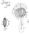
- the invention is directed to a catheter 10 having a basket-shaped electrode assembly 18 with an expander 22 providing deflection capabilities.
- the catheter 10 comprises an elongated catheter body 12 having proximal and distal ends and a control handle 16 at the proximal end of the catheter body, with the deflectable basket-shaped electrode assembly 18 being mounted at the distal end of the catheter body 12.
- the catheter body 12 comprises an elongated tubular construction having a single, axial or central lumen (not shown), but can optionally have multiple lumens if desired.
- the catheter body 12 is flexible, i.e., bendable, but substantially non-compressible along its length.
- the catheter body 12 can be of any suitable construction and made of any suitable material.
- One construction comprises an outer wall made of polyurethane or PEBAX.RTM. (polyether block amide).
- the outer wall comprises an imbedded braided mesh of stainless steel or the like to increase torsional stiffness of the catheter body 12 so that, when the control handle 16 is rotated, the distal end of the catheter body will rotate in a corresponding manner.
- the outer diameter of the catheter body 12 is not critical, but may be no more than about 8 french, more preferably 7 french. Likewise the thickness of the outer wall is not critical, but is preferably thin enough so that the central lumen can accommodate a puller wire, lead wires, sensor cables and any other wires, cables or tubes. If desired, the inner surface of the outer wall is lined with a stiffening tube (not shown) to provide improved torsional stability.
- a stiffening tube not shown
- the basket-shaped electrode assembly 18 is mounted to the distal end of the catheter body 12. As shown in FIG. 2 , the basket-shaped electrode assembly 18 comprises at plurality of spines 20 or arms (e.g., between about five to ten, and preferably about eight) mounted, generally evenly-spaced in about 360 radial degrees around the expander 22 so that the expander forms the center longitudinal axis of the electrode assembly.
- the spines 20 are all attached, directly or indirectly, to the expander 22 at their distal ends, and to the catheter body 12 at their proximal ends.
- a distal end 22D of the expander 22 is located inside or inwardly of the spines 20 where the distal end 22D of the expander is generally encircled or surrounded by the spines 20.
- each spine has a bowed, electrode-bearing portion 20B and a generally straight distal portion 20D.
- the distal portion 20D is generally coaxial with the expander 22.
- the bowed portion 20B is adapted to extend at an angle ⁇ from the distal portion 20D, where the angle ⁇ ranges between about 30 degrees (such as when the electrode assembly 18 is elongated and collapsed with the expander 22 extended distally, see FIG. 1B ) and 80 degrees (such as when the electrode assembly 18 is deployed and radially expanded with the expander drawn proximally, see FIG. 1 ).
- the assembly 18 provides a generally smooth profile at its distal end without any protrusion that may otherwise project and puncture tissue 13 in the atrium. Moreover, with a generally smooth profile at its distal end, the assembly 18 can be pivoted in a circular motion where its longitudinal axis traces a cone C to improve electrode contact with minimum risk of damage to tissue, especially in a cavernous region, such as an atrium.
- the expander 22 is moved longitudinally relative to the catheter body 12 to radially expand or contract the electrode assembly 18, so that in the radially expanded position the spines 20 bow outwardly ( FIG. 1 ) and in the elongated position the spines less bowed and straighter ( FIG. 1B ).
- the number of spines 20 can vary as desired depending on the particular application, so that the assembly 18 has at least two spines, preferably at least three spines, and as many as eight or more spines.
- the term "basket-shaped" in describing the electrode assembly 18 is not limited to the depicted configuration, but can include other designs, such as spherical or egg-shaped designs, that include a plurality of expandable arms connected, directly or indirectly, at their proximal and distal ends.
- each spine 20 comprises a flexible wire 24 with a non-conductive covering 26 on which one or more ring electrodes 28 are mounted.
- the flexible wires 24 each comprise a flat Nitinol wire
- the non-conductive coverings 26 each comprise a biocompatible plastic tubing, such as polyurethane or polyimide tubing.
- the spines 20 can be designed without the internal flexible wire 24 if a sufficiently rigid nonconductive material is used for the non-conductive covering 26 to permit radial expansion of the electrode assembly 18, so long as the spine has an outer surface that is non-conductive over at least a part of its surface for mounting of the ring electrodes 28.
- Each of the ring electrodes 28 on the spines 20 is electrically connected to an appropriate mapping or monitoring system and/or source of ablation energy by means of an electrode lead wire 29.
- Each electrode lead wire 29 extends through the control handle 16, through a lumen in the catheter body 12, and into the non-conductive covering 26 of the corresponding spine 20.
- Each lead wire 29 is attached to its corresponding ring electrode 28 by any suitable method.
- One method for attaching a lead wire 29 to a ring electrode 28 involves first making a small hole through the wall of the non-conductive covering 26. Such a hole can be created, for example, by inserting a needle through the non-conductive covering 26 and heating the needle sufficiently to form a permanent hole. The lead wire 29 is then drawn through the hole by using a microhook or the like. The end of the lead wire 29 is then stripped of any coating and welded to the underside of the ring electrode 28, which is then slid into position over the hole and fixed in place with polyurethane glue or the like.
- each ring electrode 28 is formed by wrapping a lead wire 29 around the non-conductive covering 26 a number of times and stripping the lead wire of its own insulated coating on its outwardly facing surfaces.
- the expander 22 is generally coaxial with the catheter body 12.
- the expander 22 has a distal end that is interior of the assembly 18 and proximal of the distal end of the electrode assembly 18.
- the expander 22 has a suitable length such that it has a proximal end 22P ( FIG. 1 ) that is exposed proximally of the control handle 16, a longer proximal portion that extends through a central lumen catheter body 12, and a shorter exposed distal portion extending distally of the catheter body 12 and through the assembly 18.
- the expander 22 is afforded longitudinal movement relative to the catheter body so that it can move the distal ends of the spines 20 proximally or distally relative to the catheter body 12 to radially expand and contract, respectively, the electrode assembly.
- the expander 22 comprises a material sufficiently rigid to achieve this function.
- the expander 22 comprises braided polyimide tubing 23, i.e., tubing having inner and outer layers of polyimide with a braided stainless steel mesh therebetween, as is generally known in the art.
- the expander 22 has a center, on-axis guidewire lumen 30 that extends along its entire length.
- the guidewire lumen 30 permits a guidewire to extend through the entire length of the catheter for introduction of the catheter 10 into a patient's body.
- the expander 22 also has at least one off-axis lumen 31 for uni-directional deflection, or also a second, diametrically-opposite, off-axis lumen 33 for bi-directional deflection, of the assembly 18.
- Puller wire 35 extends through lumen 31 and puller wire 37 extends through lumen 33.
- the proximal ends of the puller wires are anchored in the control handle 16 to be controlled by a deflection actuator 17 ( FIG. 1 ).
- the distal end of each puller wire is anchored at or near the distal end 22D of the expander 22, as described below.
- Surrounding each puller wire 35 and 37 is a respective compression coil 41 and 42.
- Each compression coil has a proximal end at or near the junction between the control handle 16 and the catheter body 12, and a distal end at or near the distal end of the catheter body 12.
- deflecting the expander 22 can change the degree of bowing in the spines 20.
- the degree of bowing increases (with the spines having greater curvature) on the side of the deflection and the degree of bowing decreases (with the spines having lesser curvature) on the side opposite the deflection.
- the increase in bowing advantageously enables the spines to exert greater pressure on the atrial tissue for better contact between the tissue and the electrodes on the spines.
- a user can change the shape of the electrode assembly by adjusting the longitudinal extension or withdrawal of the expander and/or by adjusting the direction and degree of deflection of the expander.
- longitudinal extension or withdrawal of the expander results in radially symmetrical change or adjustment in the electrode assembly with the degree of curvature of each spine being affected similarly
- deflection of expander results in radially asymmetrical changes with the degree of curvature of each spine being affected differently depending on their position relative to the deflection of the expander.
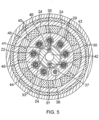
- FIGS. 4 and 5 An embodiment of a proximal junction between the proximal end of the electrode assembly 18 and distal end of the catheter body 12 is shown in FIGS. 4 and 5 .
- the junction includes a short plastic housing or tubing 43, which may be made of PEEK (polyetheretherketone).
- the housing 43 joins the distal end of the catheter body 12 and proximal end of the electrode assembly 18.
- the plastic housing 43 has a length of about 11 mm. If the plastic housing 43 is too long, it can disadvantageously affect the flexibility of the distal end of the catheter body.
- the proximal end of the plastic housing 43 is mounted on the distal end of the catheter body 12 by any suitable method, for example, with polyurethane glue or the like.
- the proximal junction also includes an outer proximal ring 48 inside the housing 43, and a tunnel member 46 in a center through-hole xx of the ring 48.
- Proximal ends of the flexible Nitinol wires 24 are mounted, for example, evenly-spaced, between the outer proximal ring 48 and the tunnel member 46, both of which may be made of polyimide.
- the outer proximal ring 48 and the tunnel member 46 may be relatively short, e.g., about 3 mm in length, compared to the length of the housing 43.
- the tunnel member 46 provides the electrode lead wires 29 with longitudinal movement within the catheter body 12 so that they do not break when the catheter body 12 bends.
- the tunnel member 46 has multiple off-axis lumens 44 through which the lead electrodes 29 extend and are allowed longitudinal movement.
- the lumens 44 may be equally spaced radially around the tunnel member 46.
- the tunnel member 46 also has a center lumen 49, through which the expander 22 extends and is allowed longitudinal movement.
- the outer proximal ring 48, the proximal ends of the wires 24 and the tunnel member 46 may be held in place in the proximal junction with polyurethane glue 45 or the like.
- proximal ends of the non-conductive coverings 26 of the spines 20 also extend into the plastic housing 43, but proximal ends of the wires 24 are stripped of the coverings 26 so that only the exposed wires 24 are mounted and anchored between the tunnel member 46 and outer proximal ring 48.
- FIGS. 6 , 7 and 8 An embodiment of a distal junction between the distal end of the expander 22 and the distal ends of the spines 20 is depicted in FIGS. 6 , 7 and 8 .
- the distal junction includes an outer tubing 40, which may be made of polyurethane or polyimide.
- the distal end 22D of the expander extends into the outer tubing 40 where it abuts with a proximal face of a puller wire anchor member 38.
- the member 38 has a generally solid cylindrical body 70 with a guidewire lumen 71 that is generally axially aligned with the guidewire lumen 30 of the expander 22.
- the member 38 also has two diametrically opposed, off-axis lumens 71 and 73 that are generally axially aligned with the lumens 31 and 33, respectively, of the expander.
- a U-shaped channel 75 is formed in a distal end of the body 70 which extends between the lumens 71 and 73.
- the puller wires 35 and 37 may be a continuous single tensile member that wraps around the distal end of the member 38 via the channel 75. This continuous pathway for the puller wire occupies minimal space in the distal junction and obviates the need to separately anchor each distal end of two puller wires.
- the guidewire lumen 71 in the member 38 may have a slight bend off the longitudinal axis to accommodate the U-shaped channel 75, or vice versa where the U-shaped channel 75 may be situated slightly off-center to accommodate the guidewire lumen 71.
- a ring 62 shorter than the outer tubing 40 sits in the tubing 40 and surrounds at least a distal portion of the member 38.
- the ring 62 may be made of metal or plastic.
- the distal ends of the flexible Nitinol wires 24 that form the spines 20 are mounted, for example, evenly-spaced, between the generally rigid ring 42 and the member 38.
- the outer tubing 40 covers the entire distal junction.
- the distal junction, including the outer tubing 40, the ring 42, the member 38, as well as the distal ends of the wires 24, is held together by polyurethane glue 63 or the like.
- the outer tubing 40 longer than the member 38, so that its proximal end extends over the distal end of the expander 22 and its distal end extends beyond the distal end of the member 38.
- the proximal end of the outer tubing 40 reinforces the attachment between the expander and the member 38.
- the non-conductive coverings 26 of the wires 24 extend into the outer tubing 40 but distal ends of the flexible wires 24 are stripped of the coverings 26 so that only the exposed wires 24 are mounted and anchored between the ring 42 and the member 38.
- the expander 22 can extend or withdraw each spine relative to the distal end of the catheter body 12.
- the proximal junction affords longitudinal movement of the expander 22 while anchoring the proximal ends of the spines 20.
- the distal junction anchors the distal ends of the spines 20 to the distal end 22D of the expander so that they are responsive to movement of the expander.
- the distal junction is proximal of the distal end of the electrode assembly 18 and interior of the electrode assembly 18 such that the electrode assembly has a generally smooth distal surface and profile so that the distal end of the electrode assembly can contact tissue.
- the rounded distal end of the electrode assembly allows the assembly to be pivoted or moved in a circular motion (with the longitudinal axis of the assembly tracing a cone C, as shown in FIG. 2 ) to contact circumferentially-surrounding tissue.
- FIGS. 10 and 10A show an electrode assembly support structure 80 that is formed from a hollow cylindrical body 81 that is precision-cut, e.g., laser cut, and shaped to a structure having a proximal stem portion 80P and a distal basket portion 80D.
- a plurality of parallel elongated spine supports 83 extending along the length of the body 81 are formed by cutting and removing parallel elongated strips 84 that extend from a first location X in the stem portion 80P to the distal end of the cylindrical body 81.
- a significant distal portion of each spine support is bowed, or otherwise bent outwardly with a curvature, at a second location Y distal of the first location X to form the basket-shape of the assembly 18.
- a straight distal end portion 83D of each spine support is bent inwardly toward the proximal stem portion 80P for attachment to the distal end of the expander by a distal junction.
- the proximal stem may be inserted into the distal end of the catheter body up to the second location Y and attached thereto by a proximal junction to allow for longitudinal movement of the expander 22.
- the stem portion 80P may be mounted between the proximal outer ring 48 and the tunnel member 46.
- the structure 80 is constructed of any suitably rigid material with shape material, e.g., Nitinol, so as to allow the structure to be flexible, elastic and sufficiently rigid to hold a predetermined configuration, yet be deformable under an applied force and able to resume the predetermined configuration upon removal of the applied force.
- shape material e.g., Nitinol
- the catheter further includes two location sensors 32 and 34 for providing location information about each of the ring electrodes 28 on the electrode assembly 18.
- a proximal location sensor 34 is mounted within the proximal junction, in the housing 43.
- the distal location sensor 36 is mounted in the distal junction, in the outer tubing 40.
- Each location sensor 32 and 34 is connected to a corresponding sensor cable 36 that extends through the catheter body 12 and control handle 16 and out the proximal end of the control handle within an umbilical cord (not shown) to a sensor control module (not shown) that houses a circuit board (not shown).
- the circuit board can be housed within the control handle 16, for example, as described in U.S. Pat. No. 6,024,739 , the disclosure of which is incorporated herein by reference.
- the sensor cable 36 comprises multiple wires encased within a plastic covered sheath. In the sensor control module, the wires of the sensor cable are connected to the circuit board.
- the circuit board amplifies the signal received from the corresponding location sensor and transmits it to a computer in a form understandable by the computer by means of the sensor connector at the proximal end of the sensor control module. Also, because the catheter is designed for single use only, the circuit board may contain an EPROM chip that shuts down the circuit board approximately twenty-four hours after the catheter has been used. This prevents the catheter, or at least the location sensor, from being used twice.
- each location sensor 32 and 34 comprises a magnetic-field-responsive coil, as described in U.S. Pat. No. 5,391,199 , or a plurality of such coils, as described in International Publication WO 96/05758 .
- the plurality of coils enables six-dimensional position and orientation coordinates to be determined.
- any suitable position sensor known in the art may be used, such as electrical, magnetic or acoustic sensors.
- Suitable location sensors for use with the present invention are also described, for example, in U.S. Pat. Nos. 5,558,091 , 5,443,489 , 5,480,422 , 5,546,951 , and 5,568,809 , and International Publication Nos.
- an electromagnetic mapping sensor has a length of from about 3 mm to about 7 mm, preferably about 4 mm.
- one of the location sensors 32 and 34 can comprise a bend sensor, which generates signals responsive to a bend radius of the spines 20.
- a bend sensor can comprise one or more piezoelectric sensors, as are known in the art, which generate electrical signals proportional to a force or torque exerted thereon when the catheter bends.
- a bend sensor can comprise one or more strain sensors, as are known in the art, or a fiber optic sensor, wherein the bend radius is determined by measuring the loss and/or back-reflection of light in an optical fiber, as is also known in the art.
- the coordinates of the distal sensor 32, relative to those of the proximal sensor 34, are determined and taken together with other known information pertaining to the curvature of the spines 20 of the basket-shaped mapping assembly 18. This information is used to find the positions of the ring electrodes 28 mounted on the spines 20.
- the proximal location sensor is situated in a second tunnel 50 provided at the proximal junction. Proximal end of the second tunnel extends into the catheter body 12 and distal end of the second tunnel extends into the housing 43.
- the tunnel 50 may be made of polyimide and has a length ranging from about 5 to 7 mm.
- the tunnel 50 protects the expander 22, electrode lead wires 29 and the sensor cable 36 that is attached to the distal location sensor 32 from being glued to the catheter at the junction of the catheter body 12 and housing 43 during assembly.
- the proximal location sensor 34 Prior to assembly, the proximal location sensor 34 is mounted in a window 52 of the second tunnel 50.
- the proximal location sensor may have a length of about 1 to 3 mm.
- the sensor cable 36 attached to the proximal location sensor 34 extends through the second tunnel 50 and catheter body 12 along with the other components. Accordingly, the cable 36 for the proximal sensor is afforded longitudinal movement at the proximal junction.
- the distal location sensor 32 is mounted at or near the distal end of the electrode assembly 18. In the depicted embodiment of FIG 6 , the distal location sensor is mounted between the outer tubing 44 and the member 38 and held in place by the glue 63.
- the sensor cable 36 attached to the distal location sensor 32 extends through one of the non-conductive coverings 26 and into the distal end of the catheter body 12.
- the control handle 16 comprises a generally cylindrical housing in which mechanisms are provided for actuating uni- or bi-directional deflection of the expander.
- the control handle has a deflection arm 18 adapted for the user to manipulate the puller wires 35 and 37 for deflecting the expander bi-directional. Rotation of the deflection arm 18 to one direction deflects the expander in that direction. Rotation of the deflection arm 18 to the opposite direction deflects expander in the opposite direction.
- a suitable control handle is described in U.S. Pat. No.
- electrode assembly 118 comprises a plurality of spines 120 or arms (e.g., between about three to five, and preferably about four) mounted, for example, generally evenly-spaced, in about 180 radial degrees around expander 122.
- the spines 120 are all attached, directly or indirectly, to the expander 122 at their distal ends, and to the catheter body 112 at their proximal and distal ends, as described above.
- the degree of bowing increases (with the spines having greater curvature) on the side of the deflection and the degree of bowing decreases (with the spines having lesser curvature) on the side opposite the deflection.
- a user can change the shape of the electrode assembly by adjusting the longitudinal extension or withdrawal of the expander and/or by adjusting the direction and degree of deflection of the expander 122.
- the expander 122 of assembly 118 may also carry a plurality of ring electrodes 128 in addition to those carried on the spines. As shown in FIG. 11B , tubing 123 of the expander 122 includes a fourth lumen 85 through which lead wires 129 extend. As such, the expander spine 122 is adapted for tissue contact in addition to providing support and deflection to the basket assembly 118.
- an electrophysiologist introduces a guiding sheath, guidewire and dilator into the patient, as is generally known in the art.
- a suitable guiding sheath for use in connection with the inventive catheter is the PREFACE. TM. Braided Guiding Sheath (commercially available from Biosense Webster, Inc., Diamond Bar, Calif.).
- the guidewire is inserted, the dilator is removed, and the catheter is introduced through the guiding sheath whereby the guidewire lumen in the expander permits the catheter to pass over the guidewire.
- the catheter is first introduced to the right atrium RA via the inferior vena cava IVC , where it passes through the septum S in order to reach the left atrium LA.
- the guiding sheath covers the spines of the electrode assembly in a collapsed position so that the entire catheter can be passed through the patient's vasculature to the desired location.
- the expander may be positioned distally of the catheter body to allow the spines of the assembly to be flattened while the assembly is passed through the guiding sheath. Once the distal end of the catheter reaches the desired location, e.g., the left atrium, the guiding sheath is withdrawn to expose the electrode assembly.
- the expander is drawn proximally or otherwise manipulated so that the spine flex outwardly between the distal and proximal junctions. With the electrode assembly radially expanded, the ring electrodes contact atrial tissue.
- the electrode assembly can be fully or partially expanded, straight or deflected, in a variety of configurations depending on the configuration of the region of the heart being mapped.
- the electrophysiologist can map local activation time and/or ablate, which can guide the electrophysiologist in diagnosing and providing therapy to the patient.
- the catheter can include one or more reference ring electrodes mounted on the catheter body, or one or more reference electrodes can be placed outside the body of the patient.
- the electrophysiologist can pivot the electrode assembly about its distal end such that the longitudinal axis of the assembly sweeps out a cone to readily bring more radial ring electrodes into contact with surrounding tissue for mapping and/or ablation without fear of puncturing tissue. Furthermore, by deflecting the expander, selected ring electrodes can be easily brought into contact with atrial tissue for improved sensing and ablation.
Landscapes
- Health & Medical Sciences (AREA)
- Life Sciences & Earth Sciences (AREA)
- Engineering & Computer Science (AREA)
- Surgery (AREA)
- General Health & Medical Sciences (AREA)
- Public Health (AREA)
- Veterinary Medicine (AREA)
- Animal Behavior & Ethology (AREA)
- Heart & Thoracic Surgery (AREA)
- Biomedical Technology (AREA)
- Medical Informatics (AREA)
- Molecular Biology (AREA)
- Physics & Mathematics (AREA)
- Biophysics (AREA)
- Cardiology (AREA)
- Pathology (AREA)
- Otolaryngology (AREA)
- Nuclear Medicine, Radiotherapy & Molecular Imaging (AREA)
- Plasma & Fusion (AREA)
- Physiology (AREA)
- Pulmonology (AREA)
- Anesthesiology (AREA)
- Hematology (AREA)
- Mechanical Engineering (AREA)
- Surgical Instruments (AREA)
- Measurement And Recording Of Electrical Phenomena And Electrical Characteristics Of The Living Body (AREA)
- Media Introduction/Drainage Providing Device (AREA)
- Electrotherapy Devices (AREA)
Applications Claiming Priority (3)
| Application Number | Priority Date | Filing Date | Title |
|---|---|---|---|
| US14/028,435 US9204929B2 (en) | 2013-09-16 | 2013-09-16 | Basket catheter with deflectable spine |
| EP18180538.3A EP3398549B1 (de) | 2013-09-16 | 2014-09-15 | Korbkatheter mit ablenkbarem dorn |
| EP14184785.5A EP2848226B1 (de) | 2013-09-16 | 2014-09-15 | Korbartiger Katheter mit steuerbarem Arm |
Related Parent Applications (2)
| Application Number | Title | Priority Date | Filing Date |
|---|---|---|---|
| EP18180538.3A Division EP3398549B1 (de) | 2013-09-16 | 2014-09-15 | Korbkatheter mit ablenkbarem dorn |
| EP14184785.5A Division EP2848226B1 (de) | 2013-09-16 | 2014-09-15 | Korbartiger Katheter mit steuerbarem Arm |
Publications (2)
| Publication Number | Publication Date |
|---|---|
| EP4233699A2 true EP4233699A2 (de) | 2023-08-30 |
| EP4233699A3 EP4233699A3 (de) | 2023-11-01 |
Family
ID=51535379
Family Applications (3)
| Application Number | Title | Priority Date | Filing Date |
|---|---|---|---|
| EP18180538.3A Active EP3398549B1 (de) | 2013-09-16 | 2014-09-15 | Korbkatheter mit ablenkbarem dorn |
| EP14184785.5A Active EP2848226B1 (de) | 2013-09-16 | 2014-09-15 | Korbartiger Katheter mit steuerbarem Arm |
| EP23180000.4A Pending EP4233699A3 (de) | 2013-09-16 | 2014-09-15 | Korbkatheter mit ablenkbarem dorn |
Family Applications Before (2)
| Application Number | Title | Priority Date | Filing Date |
|---|---|---|---|
| EP18180538.3A Active EP3398549B1 (de) | 2013-09-16 | 2014-09-15 | Korbkatheter mit ablenkbarem dorn |
| EP14184785.5A Active EP2848226B1 (de) | 2013-09-16 | 2014-09-15 | Korbartiger Katheter mit steuerbarem Arm |
Country Status (11)
| Country | Link |
|---|---|
| US (7) | US9204929B2 (de) |
| EP (3) | EP3398549B1 (de) |
| JP (1) | JP6466114B2 (de) |
| CN (1) | CN104434083B (de) |
| AU (1) | AU2014221192B2 (de) |
| CA (1) | CA2863021A1 (de) |
| DK (1) | DK2848226T3 (de) |
| ES (1) | ES2686849T3 (de) |
| IL (1) | IL234503B (de) |
| IN (1) | IN2014DE02438A (de) |
| RU (1) | RU2675081C2 (de) |
Families Citing this family (76)
| Publication number | Priority date | Publication date | Assignee | Title |
|---|---|---|---|---|
| CN107080561B (zh) | 2011-12-09 | 2020-09-11 | 麦特文申公司 | 用于神经调节的设备、系统和方法 |
| US8825130B2 (en) | 2011-12-30 | 2014-09-02 | St. Jude Medical, Atrial Fibrillation Division, Inc. | Electrode support structure assemblies |
| WO2014071372A1 (en) | 2012-11-05 | 2014-05-08 | Boston Scientific Scimed, Inc. | Devices for delivering energy to body lumens |
| CN105473089A (zh) | 2013-06-05 | 2016-04-06 | 麦特文申公司 | 靶标神经纤维的调节 |
| US9204929B2 (en) * | 2013-09-16 | 2015-12-08 | Biosense Webster (Israel) Ltd. | Basket catheter with deflectable spine |
| CN106255451B (zh) | 2014-05-06 | 2020-03-17 | 圣犹达医疗用品心脏病学部门有限公司 | 电极支撑结构组件 |
| US10118022B2 (en) | 2014-06-05 | 2018-11-06 | St. Jude Medical, Cardiology Division, Inc. | Deflectable catheter shaft section |
| US9844645B2 (en) | 2014-06-17 | 2017-12-19 | St. Jude Medical, Cardiology Division, Inc. | Triple coil catheter support |
| CN104287824B (zh) * | 2014-10-11 | 2017-09-15 | 先健科技(深圳)有限公司 | 消融导管装置 |
| US10898096B2 (en) | 2014-10-27 | 2021-01-26 | St. Jude Medical, Cardiology Division, Inc. | Apparatus and method for connecting elements in medical devices |
| US9314208B1 (en) | 2014-10-28 | 2016-04-19 | Biosense Webster (Israel) Ltd. | Basket catheter with microelectrode array distal tip |
| US9782099B2 (en) | 2014-12-31 | 2017-10-10 | Biosense Webster (Israel) Ltd. | Basket catheter with improved spine flexibility |
| US10602983B2 (en) | 2015-05-08 | 2020-03-31 | St. Jude Medical International Holding S.À R.L. | Integrated sensors for medical devices and method of making integrated sensors for medical devices |
| IL247094B (en) * | 2015-08-12 | 2021-01-31 | Biosense Webster Israel Ltd | Basket catheter with high density electrodes |
| WO2017027800A1 (en) * | 2015-08-13 | 2017-02-16 | Intact Medical Corporation | Electrosurgical method and apparatus with varying stiffness capture components |
| US10524857B2 (en) * | 2015-09-14 | 2020-01-07 | Biosense Webster (Israel) Ltd. | Dual node multiray electrode catheter |
| US20170071543A1 (en) * | 2015-09-14 | 2017-03-16 | Biosense Webster (Israel) Ltd. | Convertible basket catheter |
| US10357173B2 (en) * | 2015-09-14 | 2019-07-23 | Biosense Webster (Israel) Ltd. | Dual multiray electrode catheter |
| US10987045B2 (en) * | 2015-09-14 | 2021-04-27 | Biosense Webster (Israel) Ltd. | Basket catheter with individual spine control |
| US10130420B2 (en) * | 2015-10-08 | 2018-11-20 | Biosense Webster (Israel) Ltd. | Catheter with membraned spines for pulmonary vein isolation |
| EP4032493A1 (de) | 2015-10-21 | 2022-07-27 | St. Jude Medical, Cardiology Division, Inc. | Katheter zum hochdichten elektroden-mapping |
| US10078713B2 (en) * | 2015-12-24 | 2018-09-18 | Biosense Webster (Israel) Ltd. | Global mapping catheter contact optimization |
| US10512505B2 (en) | 2018-05-07 | 2019-12-24 | Farapulse, Inc. | Systems, apparatuses and methods for delivery of ablative energy to tissue |
| US10314505B2 (en) * | 2016-03-15 | 2019-06-11 | Biosense Webster (Israel) Ltd. | Asymmetric basket catheter |
| US10362991B2 (en) * | 2016-04-04 | 2019-07-30 | Biosense Webster (Israel) Ltd. | Convertible basket catheter |
| EP4364765A3 (de) | 2016-05-03 | 2024-07-31 | St. Jude Medical, Cardiology Division, Inc. | Bewässerter hochdichter elektrodenkatheter |
| US10537260B2 (en) * | 2016-05-06 | 2020-01-21 | Biosense Webster (Israel) Ltd. | Varying diameter catheter distal end design for decreased distal hub size |
| US10898139B2 (en) * | 2016-06-03 | 2021-01-26 | Biosense Webster (Israel) Ltd. | Spine construction for basket catheter |
| US10524859B2 (en) | 2016-06-07 | 2020-01-07 | Metavention, Inc. | Therapeutic tissue modulation devices and methods |
| US10905329B2 (en) | 2016-06-09 | 2021-02-02 | Biosense Webster (Israel) Ltd. | Multi-function conducting elements for a catheter |
| DE102016116871A1 (de) * | 2016-09-08 | 2018-03-08 | Phenox Gmbh | Vorrichtung und Verfahren zur Vorbeugung und Behandlung eines Vasospasmus |
| WO2018080985A1 (en) | 2016-10-24 | 2018-05-03 | St. Jude Medical, Cardiology Division, Inc. | Catheter insertion devices |
| US11172858B2 (en) | 2016-10-28 | 2021-11-16 | St. Jude Medical, Cardiology Division, Inc. | Flexible high-density mapping catheter |
| US12011549B2 (en) | 2017-01-19 | 2024-06-18 | St. Jude Medical, Cardiology Division, Inc. | Sheath visualization |
| US12029545B2 (en) | 2017-05-30 | 2024-07-09 | Biosense Webster (Israel) Ltd. | Catheter splines as location sensors |
| US11647935B2 (en) | 2017-07-24 | 2023-05-16 | St. Jude Medical, Cardiology Division, Inc. | Masked ring electrodes |
| CN111278497B (zh) | 2017-11-28 | 2024-01-12 | 圣犹达医疗用品心脏病学部门有限公司 | 管腔控制导管 |
| US10945626B2 (en) * | 2018-02-06 | 2021-03-16 | Biosense Webster (Israel) Ltd. | Catheter with staggered electrodes spine assembly |
| US11058315B2 (en) * | 2018-02-06 | 2021-07-13 | Biosense Webster (Israel) Ltd. | Catheter with electrode spine assembly having preformed configurations for improved tissue contact |
| WO2019213215A1 (en) | 2018-05-01 | 2019-11-07 | RIEKE, James P. | System and method for device steering, tracking, and navigation of devices for interventional procedures |
| US20190314083A1 (en) | 2018-04-11 | 2019-10-17 | Biosense Webster (Israel) Ltd. | Flexible Multi-Arm Catheter with Diametrically Opposed Sensing Electrodes |
| EP3790483B1 (de) | 2018-05-07 | 2024-08-28 | Boston Scientific Scimed, Inc. | Systeme zur filterung von hochspannungsrauschen durch gepulste feldablation |
| WO2020039392A2 (en) | 2018-08-23 | 2020-02-27 | St. Jude Medical, Cardiology Division, Inc. | Curved high density electrode mapping catheter |
| WO2020065587A2 (en) | 2018-09-27 | 2020-04-02 | St. Jude Medical, Cardiology Division, Inc. | Uniform mapping balloon |
| US11918762B2 (en) | 2018-10-03 | 2024-03-05 | St. Jude Medical, Cardiology Division, Inc. | Reduced actuation force electrophysiology catheter handle |
| US11045628B2 (en) | 2018-12-11 | 2021-06-29 | Biosense Webster (Israel) Ltd. | Balloon catheter with high articulation |
| US11850051B2 (en) | 2019-04-30 | 2023-12-26 | Biosense Webster (Israel) Ltd. | Mapping grid with high density electrode array |
| US10625080B1 (en) | 2019-09-17 | 2020-04-21 | Farapulse, Inc. | Systems, apparatuses, and methods for detecting ectopic electrocardiogram signals during pulsed electric field ablation |
| US20210093374A1 (en) * | 2019-09-26 | 2021-04-01 | Biosense Webster (Israel) Ltd. | Wiring for Multi-Electrode Catheter |
| US11497541B2 (en) | 2019-11-20 | 2022-11-15 | Boston Scientific Scimed, Inc. | Systems, apparatuses, and methods for protecting electronic components from high power noise induced by high voltage pulses |
| US11065047B2 (en) | 2019-11-20 | 2021-07-20 | Farapulse, Inc. | Systems, apparatuses, and methods for protecting electronic components from high power noise induced by high voltage pulses |
| US10842572B1 (en) * | 2019-11-25 | 2020-11-24 | Farapulse, Inc. | Methods, systems, and apparatuses for tracking ablation devices and generating lesion lines |
| US11950930B2 (en) | 2019-12-12 | 2024-04-09 | Biosense Webster (Israel) Ltd. | Multi-dimensional acquisition of bipolar signals from a catheter |
| US12029862B2 (en) * | 2019-12-20 | 2024-07-09 | Biosense Webster (Israel) Ltd. | Expandable assembly catheter |
| US11517218B2 (en) | 2019-12-20 | 2022-12-06 | Biosense Webster (Israel) Ltd. | Selective graphical presentation of electrophysiological parameters |
| US11737773B2 (en) | 2019-12-30 | 2023-08-29 | Biosense Webster (Israel) Ltd. | Non-circular working channel of an ear-nose-throat tool |
| US12097339B2 (en) | 2019-12-31 | 2024-09-24 | Biosense Webster (Israel) Ltd. | System and methods of using a catheter with an anchoring mechanism |
| WO2021208847A1 (zh) * | 2020-04-13 | 2021-10-21 | 杭州德诺电生理医疗科技有限公司 | 消融装置及其制备方法 |
| US11987017B2 (en) | 2020-06-08 | 2024-05-21 | Biosense Webster (Israel) Ltd. | Features to assist in assembly and testing of devices |
| EP4167892A1 (de) | 2020-06-19 | 2023-04-26 | Remedy Robotics, Inc. | Systeme und verfahren zur führung intraluminaler vorrichtungen im gefässsystem |
| US12048479B2 (en) | 2020-09-10 | 2024-07-30 | Biosense Webster (Israel) Ltd. | Surface mounted electrode catheter |
| US11950841B2 (en) | 2020-09-22 | 2024-04-09 | Biosense Webster (Israel) Ltd. | Basket catheter having insulated ablation electrodes and diagnostic electrodes |
| US11950840B2 (en) | 2020-09-22 | 2024-04-09 | Biosense Webster (Israel) Ltd. | Basket catheter having insulated ablation electrodes |
| US12082875B2 (en) | 2020-09-24 | 2024-09-10 | Biosense Webster (Israel) Ltd | Balloon catheter having a coil for sensing tissue temperature and position of the balloon |
| US11974803B2 (en) | 2020-10-12 | 2024-05-07 | Biosense Webster (Israel) Ltd. | Basket catheter with balloon |
| US11918383B2 (en) | 2020-12-21 | 2024-03-05 | Biosense Webster (Israel) Ltd. | Visualizing performance of catheter electrodes |
| CN112914682B (zh) * | 2021-01-26 | 2022-03-15 | 李堃 | 一种多功能胆道取石网篮 |
| US12064170B2 (en) | 2021-05-13 | 2024-08-20 | Biosense Webster (Israel) Ltd. | Distal assembly for catheter with lumens running along spines |
| CN113274124A (zh) * | 2021-06-22 | 2021-08-20 | 上海安钛克医疗科技有限公司 | 电极组件、电生理导管及电生理系统 |
| WO2023278789A1 (en) | 2021-07-01 | 2023-01-05 | Remedy Robotics, Inc. | Vision-based position and orientation determination for endovascular tools |
| US11707332B2 (en) | 2021-07-01 | 2023-07-25 | Remedy Robotics, Inc. | Image space control for endovascular tools |
| US12004804B2 (en) | 2021-09-09 | 2024-06-11 | Biosense Webster (Israel) Ltd. | Basket catheter with mushroom shape distal tip |
| US12011280B2 (en) | 2021-10-04 | 2024-06-18 | Biosense Webster (Israel) Ltd. | Electrophysiological mapping in the presence of injury current |
| US20230190357A1 (en) * | 2021-12-22 | 2023-06-22 | Biosense Webster (Israel) Ltd. | Compact Basket Probe |
| WO2023142428A1 (zh) * | 2022-01-26 | 2023-08-03 | 上海鑫律通生命科技有限公司 | 一种可双向弯曲的花键篮消融导管 |
| US20240206978A1 (en) | 2022-12-27 | 2024-06-27 | Biosense Webster (Israel) Ltd. | Electrophysiology mapping using catheter splines deflection modeling |
Citations (12)
| Publication number | Priority date | Publication date | Assignee | Title |
|---|---|---|---|---|
| WO1995002995A1 (en) | 1993-07-20 | 1995-02-02 | Biosense, Inc. | Apparatus and method for treating cardiac arrhythmias |
| WO1996005758A1 (en) | 1994-08-23 | 1996-02-29 | Trotta Frank P Jr | System and method for automated shopping |
| US5558091A (en) | 1993-10-06 | 1996-09-24 | Biosense, Inc. | Magnetic determination of position and orientation |
| WO1997024983A2 (en) | 1996-01-08 | 1997-07-17 | Biosense Inc. | Mapping catheter |
| US5772590A (en) | 1992-06-30 | 1998-06-30 | Cordis Webster, Inc. | Cardiovascular catheter with laterally stable basket-shaped electrode array with puller wire |
| WO1998029033A1 (en) | 1997-01-03 | 1998-07-09 | Biosense, Inc. | Bend-responsive catheter |
| US6024739A (en) | 1997-09-05 | 2000-02-15 | Cordis Webster, Inc. | Method for detecting and revascularizing ischemic myocardial tissue |
| US6064905A (en) | 1998-06-18 | 2000-05-16 | Cordis Webster, Inc. | Multi-element tip electrode mapping catheter |
| US6748255B2 (en) | 2001-12-14 | 2004-06-08 | Biosense Webster, Inc. | Basket catheter with multiple location sensors |
| US6973340B2 (en) | 2001-12-14 | 2005-12-06 | Biosense Webster, Inc. | Basket catheter with improved expansion mechanism |
| US7377906B2 (en) | 2004-06-15 | 2008-05-27 | Biosense Webster, Inc. | Steering mechanism for bi-directional catheter |
| US8137308B2 (en) | 2008-09-16 | 2012-03-20 | Biosense Webster, Inc. | Catheter with adjustable deflection sensitivity |
Family Cites Families (23)
| Publication number | Priority date | Publication date | Assignee | Title |
|---|---|---|---|---|
| US5662108A (en) * | 1992-09-23 | 1997-09-02 | Endocardial Solutions, Inc. | Electrophysiology mapping system |
| US5313943A (en) | 1992-09-25 | 1994-05-24 | Ep Technologies, Inc. | Catheters and methods for performing cardiac diagnosis and treatment |
| WO1996005768A1 (en) | 1994-08-19 | 1996-02-29 | Biosense, Inc. | Medical diagnosis, treatment and imaging systems |
| US5730127A (en) | 1993-12-03 | 1998-03-24 | Avitall; Boaz | Mapping and ablation catheter system |
| US6216043B1 (en) | 1994-03-04 | 2001-04-10 | Ep Technologies, Inc. | Asymmetric multiple electrode support structures |
| ATE250394T1 (de) * | 1994-10-07 | 2003-10-15 | Boston Scient Ltd | Flexible elektrodenstruktur |
| US5885278A (en) * | 1994-10-07 | 1999-03-23 | E.P. Technologies, Inc. | Structures for deploying movable electrode elements |
| US5702438A (en) | 1995-06-08 | 1997-12-30 | Avitall; Boaz | Expandable recording and ablation catheter system |
| US5848972A (en) | 1995-09-15 | 1998-12-15 | Children's Medical Center Corporation | Method for endocardial activation mapping using a multi-electrode catheter |
| US5846238A (en) | 1996-01-19 | 1998-12-08 | Ep Technologies, Inc. | Expandable-collapsible electrode structures with distal end steering or manipulation |
| US6086532A (en) * | 1997-09-26 | 2000-07-11 | Ep Technologies, Inc. | Systems for recording use of structures deployed in association with heart tissue |
| US6917834B2 (en) | 1997-12-03 | 2005-07-12 | Boston Scientific Scimed, Inc. | Devices and methods for creating lesions in endocardial and surrounding tissue to isolate focal arrhythmia substrates |
| US20100114087A1 (en) | 1998-02-19 | 2010-05-06 | Edwards Stuart D | Methods and devices for treating urinary incontinence |
| US6319251B1 (en) * | 1998-09-24 | 2001-11-20 | Hosheng Tu | Medical device and methods for treating intravascular restenosis |
| US6829497B2 (en) | 1999-09-21 | 2004-12-07 | Jamil Mogul | Steerable diagnostic catheters |
| US6771996B2 (en) | 2001-05-24 | 2004-08-03 | Cardiac Pacemakers, Inc. | Ablation and high-resolution mapping catheter system for pulmonary vein foci elimination |
| US7429261B2 (en) * | 2004-11-24 | 2008-09-30 | Ablation Frontiers, Inc. | Atrial ablation catheter and method of use |
| US8588885B2 (en) * | 2007-05-09 | 2013-11-19 | St. Jude Medical, Atrial Fibrillation Division, Inc. | Bendable catheter arms having varied flexibility |
| US8500730B2 (en) * | 2007-11-16 | 2013-08-06 | Biosense Webster, Inc. | Catheter with omni-directional optical tip having isolated optical paths |
| CA2764494A1 (en) | 2011-01-21 | 2012-07-21 | Kardium Inc. | Enhanced medical device for use in bodily cavities, for example an atrium |
| CA2831116C (en) | 2011-04-22 | 2015-04-14 | Topera, Inc. | Basket style cardiac mapping catheter having spline bends for detection of cardiac rhythm disorders |
| US8825130B2 (en) * | 2011-12-30 | 2014-09-02 | St. Jude Medical, Atrial Fibrillation Division, Inc. | Electrode support structure assemblies |
| US9204929B2 (en) * | 2013-09-16 | 2015-12-08 | Biosense Webster (Israel) Ltd. | Basket catheter with deflectable spine |
-
2013
- 2013-09-16 US US14/028,435 patent/US9204929B2/en active Active
-
2014
- 2014-08-27 IN IN2438DE2014 patent/IN2014DE02438A/en unknown
- 2014-09-02 AU AU2014221192A patent/AU2014221192B2/en not_active Ceased
- 2014-09-07 IL IL234503A patent/IL234503B/en active IP Right Grant
- 2014-09-08 CA CA 2863021 patent/CA2863021A1/en not_active Abandoned
- 2014-09-12 JP JP2014186095A patent/JP6466114B2/ja active Active
- 2014-09-15 DK DK14184785.5T patent/DK2848226T3/en active
- 2014-09-15 EP EP18180538.3A patent/EP3398549B1/de active Active
- 2014-09-15 ES ES14184785.5T patent/ES2686849T3/es active Active
- 2014-09-15 EP EP14184785.5A patent/EP2848226B1/de active Active
- 2014-09-15 EP EP23180000.4A patent/EP4233699A3/de active Pending
- 2014-09-15 RU RU2014137318A patent/RU2675081C2/ru not_active IP Right Cessation
- 2014-09-16 CN CN201410471935.8A patent/CN104434083B/zh active Active
-
2015
- 2015-12-04 US US14/960,254 patent/US9486282B2/en active Active
-
2016
- 2016-11-04 US US15/344,445 patent/US9788895B2/en active Active
-
2017
- 2017-10-16 US US15/785,373 patent/US10143394B2/en active Active
-
2018
- 2018-12-03 US US16/208,532 patent/US10575745B2/en active Active
-
2020
- 2020-03-02 US US16/806,976 patent/US11160482B2/en active Active
-
2021
- 2021-11-01 US US17/515,960 patent/US11992321B2/en active Active
Patent Citations (17)
| Publication number | Priority date | Publication date | Assignee | Title |
|---|---|---|---|---|
| US5772590A (en) | 1992-06-30 | 1998-06-30 | Cordis Webster, Inc. | Cardiovascular catheter with laterally stable basket-shaped electrode array with puller wire |
| US5391199A (en) | 1993-07-20 | 1995-02-21 | Biosense, Inc. | Apparatus and method for treating cardiac arrhythmias |
| US5443489A (en) | 1993-07-20 | 1995-08-22 | Biosense, Inc. | Apparatus and method for ablation |
| US5480422A (en) | 1993-07-20 | 1996-01-02 | Biosense, Inc. | Apparatus for treating cardiac arrhythmias |
| US5546951A (en) | 1993-07-20 | 1996-08-20 | Biosense, Inc. | Method and apparatus for studying cardiac arrhythmias |
| US5568809A (en) | 1993-07-20 | 1996-10-29 | Biosense, Inc. | Apparatus and method for intrabody mapping |
| WO1995002995A1 (en) | 1993-07-20 | 1995-02-02 | Biosense, Inc. | Apparatus and method for treating cardiac arrhythmias |
| US5558091A (en) | 1993-10-06 | 1996-09-24 | Biosense, Inc. | Magnetic determination of position and orientation |
| WO1996005758A1 (en) | 1994-08-23 | 1996-02-29 | Trotta Frank P Jr | System and method for automated shopping |
| WO1997024983A2 (en) | 1996-01-08 | 1997-07-17 | Biosense Inc. | Mapping catheter |
| WO1998029033A1 (en) | 1997-01-03 | 1998-07-09 | Biosense, Inc. | Bend-responsive catheter |
| US6024739A (en) | 1997-09-05 | 2000-02-15 | Cordis Webster, Inc. | Method for detecting and revascularizing ischemic myocardial tissue |
| US6064905A (en) | 1998-06-18 | 2000-05-16 | Cordis Webster, Inc. | Multi-element tip electrode mapping catheter |
| US6748255B2 (en) | 2001-12-14 | 2004-06-08 | Biosense Webster, Inc. | Basket catheter with multiple location sensors |
| US6973340B2 (en) | 2001-12-14 | 2005-12-06 | Biosense Webster, Inc. | Basket catheter with improved expansion mechanism |
| US7377906B2 (en) | 2004-06-15 | 2008-05-27 | Biosense Webster, Inc. | Steering mechanism for bi-directional catheter |
| US8137308B2 (en) | 2008-09-16 | 2012-03-20 | Biosense Webster, Inc. | Catheter with adjustable deflection sensitivity |
Also Published As
Similar Documents
| Publication | Publication Date | Title |
|---|---|---|
| US11992321B2 (en) | Basket catheter with deflectable spine | |
| US6748255B2 (en) | Basket catheter with multiple location sensors | |
| US6741878B2 (en) | Basket catheter with improved expansion mechanism | |
| CN105796090B (zh) | 脊柔韧性改善的篮形导管 | |
| US6961602B2 (en) | Catheter having multiple spines each having electrical mapping and location sensing capabilities | |
| EP3015064A2 (de) | Korbkatheter mit mikroelektrodenanordnung-distalspitze |
Legal Events
| Date | Code | Title | Description |
|---|---|---|---|
| PUAI | Public reference made under article 153(3) epc to a published international application that has entered the european phase |
Free format text: ORIGINAL CODE: 0009012 |
|
| STAA | Information on the status of an ep patent application or granted ep patent |
Free format text: STATUS: THE APPLICATION HAS BEEN PUBLISHED |
|
| AC | Divisional application: reference to earlier application |
Ref document number: 2848226 Country of ref document: EP Kind code of ref document: P Ref document number: 3398549 Country of ref document: EP Kind code of ref document: P |
|
| AK | Designated contracting states |
Kind code of ref document: A2 Designated state(s): AL AT BE BG CH CY CZ DE DK EE ES FI FR GB GR HR HU IE IS IT LI LT LU LV MC MK MT NL NO PL PT RO RS SE SI SK SM TR |
|
| REG | Reference to a national code |
Ref country code: DE Ref legal event code: R079 Free format text: PREVIOUS MAIN CLASS: A61B0005000000 Ipc: A61B0018140000 |
|
| PUAL | Search report despatched |
Free format text: ORIGINAL CODE: 0009013 |
|
| AK | Designated contracting states |
Kind code of ref document: A3 Designated state(s): AL AT BE BG CH CY CZ DE DK EE ES FI FR GB GR HR HU IE IS IT LI LT LU LV MC MK MT NL NO PL PT RO RS SE SI SK SM TR |
|
| RIC1 | Information provided on ipc code assigned before grant |
Ipc: A61B 5/00 20060101ALI20230925BHEP Ipc: A61B 5/287 20210101ALI20230925BHEP Ipc: A61B 18/14 20060101AFI20230925BHEP |
|
| STAA | Information on the status of an ep patent application or granted ep patent |
Free format text: STATUS: REQUEST FOR EXAMINATION WAS MADE |
|
| 17P | Request for examination filed |
Effective date: 20240430 |
|
| RBV | Designated contracting states (corrected) |
Designated state(s): AL AT BE BG CH CY CZ DE DK EE ES FI FR GB GR HR HU IE IS IT LI LT LU LV MC MK MT NL NO PL PT RO RS SE SI SK SM TR |