EP4233538B1 - Insektenverpressvorrichtung und -verfahren zum verladen von insekten in eine insektenverstau- und -freisetzvorrichtung - Google Patents
Insektenverpressvorrichtung und -verfahren zum verladen von insekten in eine insektenverstau- und -freisetzvorrichtung Download PDFInfo
- Publication number
- EP4233538B1 EP4233538B1 EP23175036.5A EP23175036A EP4233538B1 EP 4233538 B1 EP4233538 B1 EP 4233538B1 EP 23175036 A EP23175036 A EP 23175036A EP 4233538 B1 EP4233538 B1 EP 4233538B1
- Authority
- EP
- European Patent Office
- Prior art keywords
- insect
- insects
- interior volume
- release
- storage
- Prior art date
- Legal status (The legal status is an assumption and is not a legal conclusion. Google has not performed a legal analysis and makes no representation as to the accuracy of the status listed.)
- Active
Links
Images






Classifications
-
- A—HUMAN NECESSITIES
- A01—AGRICULTURE; FORESTRY; ANIMAL HUSBANDRY; HUNTING; TRAPPING; FISHING
- A01K—ANIMAL HUSBANDRY; AVICULTURE; APICULTURE; PISCICULTURE; FISHING; REARING OR BREEDING ANIMALS, NOT OTHERWISE PROVIDED FOR; NEW BREEDS OF ANIMALS
- A01K1/00—Housing animals; Equipment therefor
- A01K1/08—Arrangements for simultaneously releasing several animals
-
- A—HUMAN NECESSITIES
- A01—AGRICULTURE; FORESTRY; ANIMAL HUSBANDRY; HUNTING; TRAPPING; FISHING
- A01K—ANIMAL HUSBANDRY; AVICULTURE; APICULTURE; PISCICULTURE; FISHING; REARING OR BREEDING ANIMALS, NOT OTHERWISE PROVIDED FOR; NEW BREEDS OF ANIMALS
- A01K1/00—Housing animals; Equipment therefor
- A01K1/02—Pigsties; Dog-kennels; Rabbit-hutches or the like
- A01K1/03—Housing for domestic or laboratory animals
- A01K1/031—Cages for laboratory animals; Cages for measuring metabolism of animals
-
- A—HUMAN NECESSITIES
- A01—AGRICULTURE; FORESTRY; ANIMAL HUSBANDRY; HUNTING; TRAPPING; FISHING
- A01K—ANIMAL HUSBANDRY; AVICULTURE; APICULTURE; PISCICULTURE; FISHING; REARING OR BREEDING ANIMALS, NOT OTHERWISE PROVIDED FOR; NEW BREEDS OF ANIMALS
- A01K67/00—Rearing or breeding animals, not otherwise provided for; New or modified breeds of animals
- A01K67/30—Rearing or breeding invertebrates
- A01K67/31—Arrangements for releasing thereof into the environment
-
- B—PERFORMING OPERATIONS; TRANSPORTING
- B65—CONVEYING; PACKING; STORING; HANDLING THIN OR FILAMENTARY MATERIAL
- B65D—CONTAINERS FOR STORAGE OR TRANSPORT OF ARTICLES OR MATERIALS, e.g. BAGS, BARRELS, BOTTLES, BOXES, CANS, CARTONS, CRATES, DRUMS, JARS, TANKS, HOPPERS, FORWARDING CONTAINERS; ACCESSORIES, CLOSURES, OR FITTINGS THEREFOR; PACKAGING ELEMENTS; PACKAGES
- B65D75/00—Packages comprising articles or materials partially or wholly enclosed in strips, sheets, blanks, tubes or webs of flexible sheet material, e.g. in folded wrappers
- B65D75/28—Articles or materials wholly enclosed in composite wrappers, i.e. wrappers formed by associating or interconnecting two or more sheets or blanks
- B65D75/30—Articles or materials enclosed between two opposed sheets or blanks having their margins united, e.g. by pressure-sensitive adhesive, crimping, heat-sealing, or welding
- B65D75/32—Articles or materials enclosed between two opposed sheets or blanks having their margins united, e.g. by pressure-sensitive adhesive, crimping, heat-sealing, or welding one or both sheets or blanks being recessed to accommodate contents
- B65D75/36—Articles or materials enclosed between two opposed sheets or blanks having their margins united, e.g. by pressure-sensitive adhesive, crimping, heat-sealing, or welding one or both sheets or blanks being recessed to accommodate contents one sheet or blank being recessed and the other formed of relatively stiff flat sheet material, e.g. blister packages, the recess or recesses being preformed
- B65D75/367—Articles or materials enclosed between two opposed sheets or blanks having their margins united, e.g. by pressure-sensitive adhesive, crimping, heat-sealing, or welding one or both sheets or blanks being recessed to accommodate contents one sheet or blank being recessed and the other formed of relatively stiff flat sheet material, e.g. blister packages, the recess or recesses being preformed and forming several compartments
-
- B—PERFORMING OPERATIONS; TRANSPORTING
- B65—CONVEYING; PACKING; STORING; HANDLING THIN OR FILAMENTARY MATERIAL
- B65D—CONTAINERS FOR STORAGE OR TRANSPORT OF ARTICLES OR MATERIALS, e.g. BAGS, BARRELS, BOTTLES, BOXES, CANS, CARTONS, CRATES, DRUMS, JARS, TANKS, HOPPERS, FORWARDING CONTAINERS; ACCESSORIES, CLOSURES, OR FITTINGS THEREFOR; PACKAGING ELEMENTS; PACKAGES
- B65D85/00—Containers, packaging elements or packages, specially adapted for particular articles or materials
- B65D85/50—Containers, packaging elements or packages, specially adapted for particular articles or materials for living organisms, articles or materials sensitive to changes of environment or atmospheric conditions, e.g. land animals, birds, fish, water plants, non-aquatic plants, flower bulbs, cut flowers or foliage
Definitions
- Insects especially those reared in a laboratory, may require transportation between various stations within the laboratory and to different locations outside of the laboratory. Depending on the stage of development of the insects, different means of transportation may be appropriate.
- JP2004113061A discloses a rearing vessel for small organisms such as mites, the rearing vessel comprising a cylindrical case, an upper lid and a bottom stopper for closing the upper and lower openings of the case, a water supply tank on the bottom stopper, and a mite bed on the water supply tank.
- sterile insect technique As part of a sterile insect technique (SIT) program or otherwise, it is desirable to release known quantities of sterile insects into a target environment.
- the systems and devices described herein are used to load, store, and transport known quantities of such sterile insects in easy-to-use single-use or reusable containers. Each container may hold as few as one insect or can be scaled to hold hundreds, thousands, tens of thousands, or even more insects. To increase density, in some applications, insects are compressed as they are loaded into containers.
- Sheets or rolls of containers which may include multiple containers, may be produced, loaded, and sent for distribution. Using sheets or rolls of containers enables "dosing" selection in which set numbers of containers can be opened and released.
- the containers described herein may be shipped to end users for release. For example, a homeowner participating in a SIT program may receive, in the mail or otherwise, a package of containers including a set number of insects and instructions for releasing the insects (e.g., release one container per day for a week). The homeowner may be responsible for opening the containers and releasing the insects. For example, for a typical yard, about two containers of 1000 mosquitoes may be opened each week.
- a single-use insect storage and release device includes a cup having a cylindrical shape, and a cap.
- the insect storage and release device is configured to hold a compressed quantity of insects within an interior volume of the cup.
- the cup is placed into a retainer of a loading device with an opening of the cup facing up.
- a barrel of a syringe is loaded with a reticulated foam wafer that has a diameter about equal to a cross-sectional area of the opening.
- a quantity of insects is then loaded into the barrel. With the foam wafer and insects in the barrel, a structure supporting the barrel is used to align the barrel with the cup in the retainer.
- a plunger of the syringe is used to push the insects via the foam into the interior volume of the cup, thereby compressing the insects beneath the foam.
- foam Once foam has passed into the interior volume, loading concludes.
- the cap may then be placed on the cup to keep the insects and the foam from escaping the interior volume.
- the cap and/or the cup may include small perforations or slits to provide ventilation for the insects within the interior volume.
- FIG. 1 illustrates a perspective view of an insect storage and release device 100, according to at least one example.
- the insect storage and release device 100 may be used to store various quantities of insects (e.g., adult mosquitoes) in a compressed or non-compressed state.
- the insect storage and release device 100 may be sufficiently rigid to enable transportation of the insects between various locations (e.g., from an insect factory to a field delivery location).
- the insect storage and release device 100 may be designed for single use. For example, after the insects have been loaded into the insect storage and release device 100, as described elsewhere herein, and transported to a delivery location, a lid on the insect storage and release device 100 may be removed to free the insects from the insect storage and release device 100.
- the insect storage and release device 100 may be adapted for use in automated delivery systems. For example, the insect storage and release device 100 may be loaded into a blower system that, once the lid has been opened, removes the insects using an airstream.
- the insect storage and release device 100 which is illustrated with a top portion resting on a surface, includes a top flange 102, a bottom 104, and a side wall 106 that together define an interior volume 110, which may be referred to as an insect compartment.
- the side wall 106 may be around 20 mm tall and the interior volume may have a diameter of around 20 mm. In some examples, the side wall may be greater than or less than 20 mm tall and the diameter may be greater than or less than 20 mm.
- the dimensions of the side wall and diameter may be selected based on a quantity of insects to store in the insect storage and release device 100 and a packing density for the insects (e.g., a quantity of insects per volume). In some examples, other factors, which may relate to packing density or otherwise, such as a mortality rate (e.g., a percentage of insects that die during packing and/or transport) may also be considered.
- the insect storage and release device 100 has a cylindrical form factor, but other form factors such as rectangular, bulbous, and those corresponding to other shapes are also possible.
- the bottom 104 includes a perforated section 108.
- the perforated section 108 includes small slits, cuts, holes, or other perforations to enable air flow into and out of the interior volume 110. This allows air transfer between the interior volume 110 and outside the insect storage and release device 100.
- a lid such as one described with reference to later figures is used to seal an opening formed where the top flange 102 and an upper edge of side wall 106 intersect.
- the illustrated insect storage and release device 100 is formed from a thermoformable plastic.
- other materials may be employed such as foil, paper, compostable products, rubbers, silicone/urethane, foam, 3D printed resin and filament, insect food (e.g., sucrose, bread, etc.).
- the material used may be color coded to signify a characteristic such as volume of the container or quantity of insects held therein.
- the material may also be tinted (e.g., tinted plastic), UV protected (e.g., UV protected plastic), and have color-changing properties.
- the insect storage and release device 100 may also be loaded with food (e.g., sugar water, sugar capsule, etc.).
- food e.g., sugar water, sugar capsule, etc.
- the sugar water mixture is placed on the opposite side of the perforated section 108 and/or included in a foam wafer placed in the insect storage and release device 100.
- the insect storage and release device 100 is loaded directly from an insect sortation system.
- the insect sortation system may be configured to singulate and sort insects based on predefined characteristic (e.g., sex, species, size, etc.). Once singulated, the insects can be blown, driven, or otherwise loaded into the insect storage and release devices 100 from a singulation pathway of the insect sortation system. In some examples, insects from the singulation pathway are loaded into a holding chamber, and the insects are loaded from the holding chamber into the insect storage and release device 100. Whether using a singulation system or otherwise, the insect storage and release device 100 may be used to store insects of a particular characteristic (e.g., all male insects, all female insects, etc.).
- FIG. 2 illustrates a perspective view of an insect storage and release device 200, according to at least one example.
- the insect storage and release device 200 is an example of the insect storage and release device 100.
- the insect storage and release device 200 includes a foam section 212.
- a cylindrical portion of the foam section 212 extends into the interior volume 210, while a rectangular portion of the foam section 212 extends along the a top flange 202 of the insect storage and release device 200.
- the foam section 212 in this example, may form a lid for enclosing the interior volume 210.
- the insect storage and release device 200 does not include a perforated section within bottom 204 or side wall 206.
- a lid is also used to seal the opening to the interior volume 210 (e.g., along the top flange 202).
- the lid may be provided and formed of aluminum foil, plastic, or other material.
- the lid may include a perforate section to enable airflow via the lid and the foam section 212.
- the insect storage and release device 200 also includes a perforated section (e.g., when the lid forms an airtight seal).
- the illustrated foam section 212 is a reticulated foam. However, any other open cell foam, silicone, plastic, or other material capable of being compressed similarly to such open-cell foams, etc. may be employed in place of the reticulated foam.
- the foam section 212 may be soaked in food, such as sugar water, for insects within the interior volume 210.
- the interior volume 210 of the insect storage and release device 200 (and any other insect storage and release device described herein) is loaded with insect food such as a piece of fruit, sugar water, and any other such food.
- food is supplied to insects within the insect storage and release device 200 (or within any other insect storage and release device) through openings in the bottom 204, the side wall 206, and/or the lid when these openings contact the food.
- the insect storage and release device 200 (or any of the other insect storage and release devices described herein) may be placed on a towel, sponge, foam, or other absorbent object that has absorbed a liquid food (e.g., sugar water).
- a pressure-maintaining item is installed in between the foam section 212 and the lid.
- the pressure-maintaining item which may include a variable force spring, a rigid pieces of material, such as a rigid plastic or metallic disk, a constant force spring, or other such item, may function to apply and/or maintain a constant pressure within the interior volume 210.
- the pressure-maintaining item can be added, followed by the lid.
- the pressure-maintaining item may exert a force on the foam section 212 to ensure a constant pressure is maintained inside the interior volume 210.
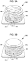
- FIGS. 3A and 3B illustrate a first perspective view and a second perspective view of an insect storage and release device 300, according to a few examples.
- insects are stored in a compressed state.
- insects are stored in an uncompressed state.
- the insect storage and release device 300 is an example of the insect storage and release devices 100 and 200.
- the insect storage and release device 300 includes a lid 314 attached to a top flange 302 that encloses an interior volume 310.
- the insect storage and release device 300 also includes a foam section 312 located within the interior volume 310 between the lid 314 and a population of insects 316.
- the lid 314 includes an adhesive backing that is used to seal the lid to a top surface of the top flange 302.
- the lid 314 may be formed from drywall tape (e.g., Tyvek (R) brand tape), peelable foil, perforated plastic, any other similar materials.
- the lid 314 is formed from the foam section 312 or a second foam section.
- This example insect storage and release device 300 relies on air flow via the lid 314, i.e., the bottom 304 and the wall 306 are not perforated.
- the lid 314 includes perforations and/or is formed from a material that allows breathability (e.g., air flow in and out of the interior volume 310).
- breathability e.g., air flow in and out of the interior volume 310.
- one or more of the lid, 314, the bottom 304, or the wall 306 may be perforated.
- the insect storage and release device 300 in FIGS. 3A and 3B includes a population of insects 316a and 316b within the interior volume 310 of the insect storage and release device 300.
- the population of insects 316a in the insect storage and release device 300a have been compressed into the interior volume 310 using a compression device such as the one described with later figures.
- the insects are compressed to between substantially 100-300 insects per milliliter, less than 100 insects per milliliter, or greater than 100 insects per milliliter.
- the insect population 316a may include around 2000 adult insects (e.g., mosquitoes).
- the insect population may be packed at a pressure of between substantially 0.5 PSI (3,45 kPa) and 3 PSI (20,68 kPa).
- this pressure may be measured based on a force applied to a packing actuator (e.g., at a handle 550 of a compression apparatus 534) given the surface area of a piston (e.g., a plunger 548) pushing against the population of insects (e.g., insects 516).
- the pressure may be lower than 0.5 PSI (3,45 kPa) and may be higher than 3 PSI (20,68 kPa).
- the population of insects 316b in the insect storage and release device 300b have not been compressed. As such, far fewer (e.g., around 25-50) insects make up the population of insects 316b.
- a device is configured to store a single insect.
- the insects 316 are compressed at least until some predefined packing pressure of the interior volume 310 is reached.
- the insects may be suppressed using a reduced temperature, a gas, or other such method to reduce physical activity and movement.
- compressing of the interior volume 310 is performed at some predefined temperature (e.g., between substantially 0 degrees C and 10 degrees C) and/or while or after exposing the insects to a gas such as CO2 or Nitrogen to immobilize them.
- the predefined temperature is less than 0 degrees C and greater than 10 degrees C.
- the insect storage and release device 300 may be shipped, transported, stored, or otherwise held at a constant holding temperature (e.g., between substantially 11 degrees C and 15 degrees C). In some examples, the constant holding temperature is less than 11 degrees C and greater than 15 degrees C.
- FIGS. 4A-4C respectively illustrate perspective views of an insect storage and release device 400 including various lid configurations 414a-414c, according to various examples.
- the insect storage and release device 400 is an example of the insect storage and release devices 100-300.
- the lids 414 may be reusable or disposable. In some examples, the lids 414 may be customized per application.
- the lids 414 may also include locking features and/or tamper-resistant features (e.g., foil that breaks when opened).
- the lid 414 may include a locking feature that prevents children from unlocking the insect storage and release device 400 (e.g., child proof lock). In some examples, the locking feature may be unlocked only by one who has a key or by one who has a combination.
- the locking feature is a detent mechanism that includes a first portion connected to the lid and a second portion connected to the body.
- the detent mechanism may be configured to arrest rotation of the lid relative to the body.
- the detent mechanism is mechanically manipulated in order to remove the lid from the body.
- the insect storage and release device 400a illustrated in FIG. 4A includes the lid 414a.
- the lid 414a includes a planar piece 416 (e.g., a thin membrane of material) and an adhesive ring 418.
- the adhesive ring 418 seals the planar piece 416 to a top surface 420 of the top flange 402.
- the planar piece 416 also includes a tab 422 that corresponds to a similar shaped structure on the top flange 402. In some examples, the tab 422 is gripped by a user when opening the container to reveal the interior volume 410.
- the adhesive ring 418 is formed as a planar sheet.
- a perimeter portion may adhere to the top surface 420 and the planar piece 416 and an inner portion may adhere to a foam section or other object disposed within the interior volume 410 and the planar piece 416.
- removal of the planar piece 416 may also include removal of the foam section.
- the insect storage and release device 400b illustrated in FIG. 4B includes the lid 414b.
- the lid 414b includes a lid bottom 424 and a lid wall 426 surrounding the lid bottom 424.
- the lid 414b is installed into the interior volume 410 via the opening located within the top flange 402.
- the lid 414b is held within the interior volume 410 by an interference fit between an exterior surface of the lid wall 426 and an interior surface of the side wall 406.
- the insect storage and release device 400c illustrated in FIG. 4C includes the lid 414c.
- the lid 414c includes the lid bottom 424 and the lid wall 426 surrounding the lid bottom 424.
- the lid 414c also includes a connecting portion 428 that connects the top flange 402 and the lid bottom 424.
- the lid 414c functions similarly as described with reference to the lid 414b.
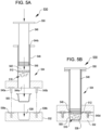
- FIGS. 5A and 5B illustrate side sectional views of an example insect compression device 530 for loading insects into one of the insect storage and release devices described herein, according at least one example.
- the insect compression device 530 is used to load insects into insect storage and release devices 500 (e.g., the insect storage and release devices 100-400), and, in some examples, this may include compressing the insects into the insect storage and release devices 500.
- insect storage and release devices 500 e.g., the insect storage and release devices 100-400
- this may include compressing the insects into the insect storage and release devices 500.
- at least some of the insect populations 316 were loaded into their respective insect storage and release devices 300 using an insect compression device such as the insect compression device 530.
- the insect compression device 530 is used to load a single insect storage and release device, but it should be understood that multiple insect compression devices 530 may be held in any suitable combination and used to simultaneously load multiple insect storage and release devices with insects.
- plurality of insect compression devices 530 may be arranged into a two-dimensional array of
- the insect compression device 530 includes a retainer block 532 and a compression apparatus 534.
- the retainer block 532 is configured to receive and retain an insect storage and release device 500 while the insect storage and release device 500 is being loaded with insects.
- the compression apparatus 534 is used to compress the insects into the insect storage and release device as it is retained by the retainer block 532.
- the retainer block 532 includes a set of alignment holes 536a-d surrounding a concave depression 538.
- the alignment holes 536 correspond to a set of alignment posts 540a-d of the compression apparatus 534, and are used to align the compression apparatus 534 with the retainer block 532.
- FIGS. 5A and 5B only two of the alignment holes 536 and two of the alignment posts 540 are illustrated. The other two may be located on opposite sides of their respective parts. In some examples, other alignment features may be employed or none may be used.
- the concave depression 538 is configured to receive and retain the insect storage and release device 500.
- the size and shape of the concave depression 538 may correspond to an exterior form factor of the insect storage and release device 500.
- the concave depression 538 may more or less has a cylindrical shape that corresponds to the cylindrical shape of the insect storage and release device 500 (e.g., such as the insect storage and release devices 100-400 described with respect to FIGS. 1-4 ).
- the concave depression 538 may have a different size and shape.
- the concave depression 538 may be bulbous to correspond to the insect storage containers described with respect to FIG. 6 .
- the compression apparatus 534 includes a chamber 542 including a distal opening 544a and a proximate opening 544b, a plunger 546 including a distal end 548 and a handle 550, along with the alignment posts 540 introduced previously.
- the chamber 542 defines an interior volume extending between the two openings, 544a and 544b.
- the plunger 546 is configured to travel longitudinally (e.g., translate) within the interior volume of the chamber 542.
- a user or a robotic device may exert a force on the handle 550 (e.g., either pushes to move the distal end 548 toward the distal opening 544a or pulls to move the distal end 548 toward the proximate opening 544b).
- the compression apparatus 534 is separated from the retainer block 532.
- An insect storage and release device 500 is loaded into the concave depression 538 of the retainer block 532.
- the plunger 546 is pulled back within the chamber 542 to define a loading volume extending within the chamber 542 between the distal opening 544a and the distal end 548 (e.g., the distal end 548 is moved adjacent to the proximate opening 544b).
- a foam section 512 e.g., the foam section 512 and/or a lid
- the chamber 542 via the distal opening 544a until it wrests against the distal end 548.
- a population of insects 516 may then be loaded into the chamber 542 via the distal opening 544a.
- the distal end 548 is removed entirely from the chamber 542 and the population of insects 516 and the foam section 512 are loaded via the proximate opening 544b.
- the compression apparatus 534 and the retainer block 532 are brought into alignment via the alignment posts 540 and the alignment holes 536.
- the plunger 546 is moved through the interior volume of the chamber 542 such that the distal end 548 pushes the foam section 512 and the insects 516 toward the retainer block 532, which includes the insect storage and release device 500 loaded into the concave depression 538.
- a packing pressure of substantially 0.5 PSI (3,45 kPa) and 3 PSI (20,68 kPa) may be applied to the insects 516 during packing. This pressure may depend on the force applied at the handle 550 given an area of the plunger 546.
- the insect compression device 530 may be separated from the retainer block 532 and the loaded insect storage and release device 500 may be removed from the concave depression 538.
- a lid may be loaded into the chamber 542 and translated within the interior volume as part of compressing the insects 516.
- the foam section 512 may be added to provide compliance during compression as well as to reduce damage to the insects 516 (e.g., the foam section 512 provides pressure on the insects 516, but does so without crushing the insects 516).
- the foam section 512 also allows the insects 516 to breathe.
- the insect compression device 530 includes any suitable compression cylinder/piston arrangement, cam shaft compression arrangement, or other suitable compression arrangement. This may enable automated loading. As described elsewhere herein, multiple insect compression devices 530 may be held together in an array of insect compression devices 530 to enable loading of multiple insect storage and release devices 500 simultaneously.
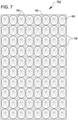
- the number of insects within each of the insect storage and release devices 600 on the sheet 756 may vary (e.g., 1 insect in one and 20 insects in another) or may be consistent (e.g., a full sheet of insect storage and release devices 600 each including 1 insect).
- the sheet 756 is manufactured and loaded based on an order for a particular number of insects to be released at some dosage interval (e.g., 1 insect on a first day, 5 insects on a second day, 10 insects on a third day, etc.).
- the number of insect storage and release devices 600 in the sheet 756 may be defined as an array having any suitable number of rows and columns (e.g., 10 x 10, 1 ⁇ 1, 10 x 1, etc.).
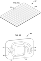
- FIG. 8A illustrates a perspective view of an example insect storage system 854, according to at least on example.
- the insect storage system 854 is an example of the insect storage system 754.
- the insect storage system 854 may be used store one or more insects.
- the insect storage system 854 may include a bottom section 858 (e.g., a microplate) that includes a plurality of wells 856.
- the bottom section 858 may be enclosed by a lid with flexible protrusions sized and configured to extend into the interior volumes of the wells 856 of the insect storage system 854.
- the insect storage system 854 may also be used to compress insects into the wells 856.
- the insect storage system 854 may include perforations to allow air exchange and/or feeding.
- FIG. 8B illustrates a perspective view of an example insect rearing and storage device 857, according to at least one example.
- the insect rearing and storage device 857 is configured to house insects as they develop from a larva stage through the pupa stage and onto full adulthood.
- the insect rearing and storage devices 857 are formed in a sheet such that many such devices 857 are included as part of one structure (e.g., a sheet of insect rearing and storage devices 857).
- the insect rearing and storage device 857 includes a pouch 862 in which is formed a pocket 860.
- the pocket 860 forms a main chamber of the insect rearing and storage device 857.
- the insect rearing and storage device 857 also includes a first duct 864 connected to a first side of the pocket 860 and extending in a first direction and a second duct 866 connected to a second side of the pocket 860 and extending in a second direction.
- the first duct 864 is configured to retain an aqueous solution, larvae insect food 868, and one or more insect larvae.
- the second duct 866 is configured to retain adult insect food 870.
- the first duct 864 includes a proximate end that terminates at the pocket 860 and a distal end that terminates radially from the pocket 860.
- the second duct 866 includes a proximate end that terminates at the pocket 860 and a distal end that terminates laterally from the pocket 860.
- one or more larvae and water are added to the first duct 864 while the insect rearing and storage device 857 is in the illustrated orientation.
- the larvae feed on the larvae insect food 868 and develop into pupae.
- the device 857 is rotated 90 degrees to the left. This causes the pupae to move through the first duct 864 and into the pocket 860, e.g., by gravity.
- the pupae are suspended in water that drained from first duct 864 or other water while the develop into adults. Once adults, the insects can access the adult insect food 870 in the second duct 866.
- the insect rearing and storage device 857 includes a perforated section disposed at a suitable location of the pocket 860.
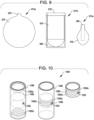
- FIG. 9 illustrates side section views of insect loading and storage systems 974a-c, according to various examples.
- the insect loading and storage system 974 is used to compress insects into a balloon 976 using three different approaches.
- the system 974a includes the balloon 976 having an opening 978.
- the insects are loaded into the balloon 976 via the opening 978 with the balloon in an inflated state. Once within the balloon 976, the air can be evacuated from the balloon 976 to compress the insects.
- the system 974b includes the balloon 976 with the opening 978 stretched over a container 980.
- the insects are loaded into the balloon 976 with the opening 978 stretched in this manner. Once within the balloon 976, the air can be evacuated from the balloon 976 to compress the insects.
- the system 974c includes the balloon 976 and a loading straw 982.
- the loading straw 982 is inserted into an opening of the balloon 976.
- the insects are loaded into the balloon 976 via the loading straw 982. Once the insects have been loaded, the loading straw 982 may be removed from the balloon 976.
- FIG. 10 illustrates perspective views of an insect loading and storage system 1084, according to at least one example.
- the insect loading and storage system 1084 is used to compress insects into a storage container 1086.
- the storage container 1086 includes an opening 1092 through which insects are loaded into an interior volume 1088. Once the insects have been loaded into the interior volume 1088, moveable walls 1090a and 1090b are moved to compress the interior volume 1088 and the insects found therein. Following this action, the moveable walls 1090a and 1090b may be moved relative to the opening 1092 to enable other insects to be loaded into other portions of the storage container 1086 formed by different moveable walls 1090.
- loading insects may be include cooling, gassing using CO2 or other suitable gas, or other suitable techniques to immobilize the insects.
- the temperature may be held between 9 degrees C and 14 degrees C.
- the insects are stored at this temperature, whether under compression or otherwise.
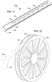
- FIG. 11 illustrates a perspective view of an example insect release system 1194, according to at least one example.
- the insect release system 1194 includes a plurality of insect storage and release devices 100 arranged into a top strip 1196, a bottom strip 1198, and a series of sprocket holes 1199.
- the insect release system 1194 takes the form factor of a film strip and can be loaded into an insect release device that is configured to open the insect storage and release devices 100 release insects disposed therein.
- the insect release device may include one or more sprockets of other structure for indexing the insect release system 1194 between the insect storage and release devices 100. For example, such indexing can be achieved by the one or more sprockets engaging the sprocket holes 1199.
- the top strip 1196 includes an adhesive backing that connects the top strip 1196 to the bottom strip 1198.
- the top strip 1196 may be separated from the bottom strip 1198 to release the insects held within the insect storage and release devices 100.
- the insect release device may include a blower to blow the insects from the insect storage and release devices 100.
- FIG. 12 illustrates an embodiment of the insect release system 1194 that is embodied in a film strip on a reel 1201.
- the insect release system 1194 includes the bottom strip 1198 and the top strip 1196.
- the reel 1201 is loaded into an insect release device and the top strip 1196 is fed to a second reel and the bottom strip is fed to a third reel. In this manner, as the second and third reels are turned, the top strip 1196 will be removed from the bottom strip 1198 thereby exposing the insects.
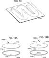
- FIGS. 14A and 14B illustrate perspective views of insect storage and release systems 1400a and 1400b, according to at least one example.
- the insect storage and release systems 1400a and 1400b may be referred singularly as the insect storage and release system 1400.
- a single insect storage and release system 1400 may constitute an insect storage and release system.
- the insect storage and release system 1400 may be configured to store insects in between planar layers of material. For example, a single layer of insects one-insect thick may be loaded into a bottom container of the insect storage and release system 1400. Next, a lid may be placed on top of the bottom container to enclose the insects within the bottom container.
- insects may be formed on top of the earlier-formed layer in a similar manner (e.g., a bottom container filled with insects and enclosed with a lid). To release the insects, the lid may be removed from the respective bottom container to reveal the interior volume.
- the insect storage and release systems 1400 may enable dense storage, transportation, and release of insects such as adult mosquitoes.
- the insect storage and release system 1400 includes a bottom container 1410 and a lid 1412.
- the bottom container 1410 includes a floor 1414 and a wall 1416 that encircles the wall 1416 to define an interior volume.
- the lid 1412 is sized to seal with a perimeter edge of the wall 1416 to enclose the interior volume of the bottom container 1410. When assembled, the lid 1412 may be brought towards the floor 1414 at least until a perimeter edge of the lid 1412 engages with the perimeter edge of the wall 1416 and/or interior surfaces of the wall 1416.
- the insect storage and release system 1400 may hold insects in a compressed state by pressing the lid 1412 against the bottom container 1410 to a predetermined pressure level while the insects are held in place between the lid and the bottom container.
- the insects may be loaded in accordance with a packing pressure, as described herein.
- the packing pressure may be measured given a force applied to the lid 1412 as it is brought into contact with the bottom container 1410 and a surface area of the bottom container 1412.
- the packing pressure may be substantially between 0.5 PSI (3,45 kPa) to 3 PSI (20,68 kPa).
- the pressure may be lower than 0.5 PSI (3,45 kPa) and may be higher than 3 PSI (20,68 kPa).
- one or more pressure-maintaining items such as pneumatic cylinders or other resilient devices (e.g., spring) may be interposed between one or more layers of bottom containers 1410 and/or lids 1412 to maintain a constant compressive force between layers.
- the packing pressure may be used for packing insects in other insect storage and release systems described herein.
- combinations of bottom containers 1410 and lids 1412 may be stacked on top of each other to create a stacked arrangement of insect storage and release systems 1400.
- the stacked arrangement of insect storage and release systems 1400 may be placed within a cylindrical tube or tube having a different cross section for bottom containers 1410 and lids 1412 having different cross sections (e.g., rectangular, etc.). The tube may function to retain the stacked insect storage and release systems 1400 and provide rigidity when the insect storage and release systems 1400 are transported.
- all insect storage and release systems 1400 within the tube may be translated within the tube until a top insect storage and release system 1400 is adjacent a top opening of the tube.
- the lid 1412 of the top insect storage and release system 1400 may be removed and the insects within the corresponding bottom container 1410 may be free to exit the bottom container 1410 and/or the tube.
- Releasing insects from one bottom container 1410 may constitute a metered "dose" of insects, where a dose includes a quantity of insects from a discrete layer of the insect storage and release system (or from the entire system if only a single layer is employed).
- the number of insects loaded into the bottom container 1410 may be metered such that each bottom container 1410 holds roughly the same quantity of insects. It should be appreciated that different sized doses of insects may be stored in different layers. For example, a first layer may include 100 insects, a second layer may include 50 insects, and a third layer may include 200 insects.
- the insects such as mosquitoes
- the bottom container 1410 This may include suppressing (e.g., sedating or otherwise reducing the energy level) the insects before placing them in the bottom container 1410.
- the lid 1412 is releasably coupled with the wall 1416. In this manner, the insects may be retained within the volume bounded by the floor 1415, the wall 1416, and the lid 1412.
- the lid 1412 may be releasably coupled with the wall 1416 using any suitable coupling such as a hook and loop fastener (e.g., Velcro ® brand hook and loop fastener), adhesive, or other coupling disposed at the perimeter edges.
- a hook and loop fastener e.g., Velcro ® brand hook and loop fastener
- adhesive e.g., glue
- the lid 1412 for that layer may be removed from the respective bottom container 1410 to reveal the interior volume. At this point, the insects may be free to fly from the bottom container 1410.
- a blower, heater, and/or any other revival device may be arranged to encourage evacuation of the insects from the bottom container 1410.
- At least some bottom containers 1410 in a stack of insect storage and release systems 1400 may hold different quantities of insects.
- a dosing requirement for a particular application may require a first insect quantity to be released on a first day, a second insect quantity to be released on a second day, and a third insect quantity to be released on a third day.
- a stack of insect storage and release systems 1400 may be formed in which a top insect storage and release system 1400 may include the first insect quantity, a middle insect storage and release system 1400 may include the second insect quantity, and a bottom insect storage and release system 1400 may include the third insect quantity.
- the stack of insect storage and release systems 1400, whether in a tube or not, may be shipped with instructions for release.
- the instructions may inform a user that on a first day remove the lid 1412 of the top insect storage and release system 1400, on the second day remove the bottom container 1410 of the top insect storage and release system 1400 and the lid 1412 of the middle insect storage and release system 1400 and, and on the third day remove the bottom container 1410 of the middle insect storage and release system 1400 and the lid 1412 of the bottom insect storage and release system 1400.
- the insect storage and release systems 1400a and 1400b are structurally similar, with the exception that the insect storage and release system 1400b also includes a floor opening 1408 in the floor 1414b of the bottom container 1410b and a lid opening 1418 in the lid 1412b.
- the floor opening 1408 and the lid opening 1418 may be sized to slide onto a mounting axle or other elongate member of a mounting structure 1520.
- the mounting structure 1520 may include a bottom platform 1522 (e.g., a support foot) and an elongate cylindrical axle 1524 that extends vertically from the bottom platform 1522.
- the insect storage and release systems 1400b may be loaded onto the elongate cylindrical axle 1524 one by one, e.g.,, by placing a first bottom container 1410 on the elongate cylindrical axle 1524, loading insects into the first bottom container 1410, installing a first lid 1412, installing a second bottom container 1410, loading second insects into the second bottom container 1410, installing a second lid 1412, and repeating for subsequent layers.
- the bottom platform 1522 may function to support the insect storage and release systems 1400b and the axle 1524 may function to align the insect storage and release systems 1400b with each other.
- the diameter of the floor opening 1408 and the diameter of the lid opening 1418 may be sized to be slightly larger than an outside diameter of the elongate cylindrical axle 1524.
- the mounting structure 1520 may also include a removable lid 1526.
- the removable lid 1526 may be removed from the axle 1524 when the insect storage and release systems 1400 are being loaded and when insects are being released from an insect storage and release system 1400.
- the mounting structure 1520 may be sized to be received by a cylindrical container.
- the mounting structure 1520 is illustrated as including sections of foam 1528 (e.g., reticulated foam) arranged into layers.
- the mounting structure 1520 may be placed within a cylindrical container with the insects being placed between layers of the insect storage and release systems 1400 and the reticulated foam sections 1528.
- the reticulated foam sections 1528 may be any other open cell foam, silicone, plastic, or other material capable of being compressed may be employed in place of the reticulated foam.
- the reticulated foam sections 1528 may occupy any excess volume within the interior volume and enable compression of the insects within the interior volume.
- the reticulated foam sections 1528 may be soaked in sugar water to provide food for insects within the interior volume.
- the insect storage and release system 1400 has a cylindrical form factor (i.e., the bottom container 1410 and the lid 1412 have circular cross or ovoid sections), but other form factors such as rectangular, triangular, spherical, bulbous, and other shapes are also possible.
- FIG. 16 illustrates a perspective view of an insect storage and release system 1600, according to at least one example.
- the insect storage and release system 1600 includes a central axle 1602 and a plurality of insect retaining structures 1604a-1604N extending radially from the central axle 1602.
- Each insect retaining structure 1604 is removably coupled to the central axle 1602 at a perimeter edge 1606.
- the retaining structures 1604 may be coupled using an adhesive or hook and loop fasteners.
- the central axle 1602 may include a plurality of slots into which perimeter edges 1606 of the retaining structures 1604 may be installed and securely held.
- the retaining structures 1604 may include one or more sheets of planar material such as paper, plastic, metal, etc.
- at least two retaining structures 1604a may form an insect storage and release subsystem by which insects may be stored.
- the retaining structure 1604a may function as a containing layer of the subsystem to define an interior volume and may be used to retain a quantity of insects
- the retaining structure 1604b may function as a lid layer of the subsystem to define a lid for the containing layer.
- the retaining structure 1604a may also function as a lid layer of a subsystem that includes the retaining structure 1604N functioning as the containing layer.
- the retaining structures 1604 may function to retain other elements that are used to store insects.
- structures similar to insect storage and release systems 1400 may be loaded in between the retaining structures 1604, and held in compression by the retaining structures 1604.
- the insects may be released from the insect storage and release system 1600 by separating the top and bottom retaining structures 1604 that are holding the insects.
- the insects held between the retaining structure 1604a and the retaining structure 1604N may be free for release.
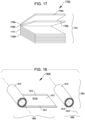
- FIG. 17 illustrates a perspective view 1704 of an insect storage and release system 1700, according to at least one example.
- the insect storage and release system 1700 includes a plurality of storage layers 1706a-1706N stacked on top of each other.
- each storage layer 1706 includes a top planar section 1708a connected to a bottom planar section 1708b via a joint section 1710.
- the planar sections 1708 and joint section 1710 may be formed from the same material or from different materials.
- a stack of storage layers 1706 may be held within a storage container such as a box or other structure. In some examples, each storage layer 1706 may hold some predefined quantity of insects between the top planar section 1708a and the bottom planar section 1708b.
- the top planar section 1708a may be folded back via the joint section 1710 to reveal an interior surface of the bottom planar section 1708b. In this orientation, the insects may be placed on the interior surface of the bottom planar section 1708b. Once a sufficient quantity of insects has been placed, the top planar section 1708a may be folded down and toward the bottom planar section 1708b. In this manner, the insects may be trapped and held between an interior surface of the top planar section 1708a and the interior surface of the top planar section 1708a. To release insects, the top planar section 1708a may be folded back again to reveal the interior surface of the bottom planar section 1708b. At this point, the insects may be free to fly from the interior surfaces of the planar sections 1708. In some examples, a blower, heater, and/or any other revival device may be arranged to encourage evacuation of the insects from the interior surface of the planar sections 1708.
- FIG. 18 illustrates perspective views of an insect storage and release system 1800, according to at least one example.
- FIG. 18 also illustrates the insect storage and release system 1800 in a rolled state 1806 and a partially rolled state 1808 about a roll axis 1816.
- the insect storage and release system 1800 is formed from a single pliable mat 1812 that includes a first side 1810a and a second side opposite the first side.
- the pliable mat 1812 is rolled around a mandrel 1818 or some other suitable cylindrical structure.
- insects may be held between coaxial layers.
- the pliable mat 1812 may be rolled out as in the partially rolled state 1808, and insects (e.g., in a sedated state) may be placed on the first side 1810a.
- insects e.g., in a sedated state
- the pliable mat 1812 may be rolled about the roll axis 1816 such that the insects are held between the first side 1810a and the second side.
- the pliable mat 1812 also includes an insect retaining material and/or coating disposed on at least the first side 1810a.
- an open-cell foam may be provided on the first side 1810 to give the insects some place to roost or otherwise go when the pliable mat 1812 is rolled.
- At least some portion of the pliable mat 1812 may be unrolled. In this manner at least some of the insects held between the layers may be exposed to the open air. At this point, the insects may be free to fly from the pliable mat 1812.
- a blower, heater, and/or any other revival device may be arranged to encourage evacuation of the insects from the pliable mat 1812.
- the pliable mat 1812 also includes one or more retaining devices 1814.
- the retaining devices 1814 which may be located on one or both sides 1810 and/or as a separate device, are provided to retain the pliable mat 1812 in the rolled state 1808.
- the retaining devices 1814 may include hook and loop fasteners (e.g., hooks on the first side 1810a and loops on the second side) that couple as the pliable mat 1812 is rolled about the roll axis 1816.
- the retaining devices 1814 may also be used to maintain a suitable compression force between layers of the roll.
- a tension for rolling the pliable mat 1812 may be computed based on a desired compression force between layers.
- the retaining devices 1814 may be configured to maintain this compression force by holding the layers.
- FIG. 19 illustrates a perspective view 1904 of an insect storage and release system 1900, according to at least one example.
- the insect storage and release system 1900 includes a plurality of storage layers 1906a-1906N stacked on top of each other and connected to each other via a joint section 1910.
- the storage layer 1906a includes at least a planar section 1908a connected to a planar section 1908b via a joint section 1910a.
- the planar section 1908a includes a first surface 1912a and a second surface 1912b.
- the planar section 1908b includes a third surface 1912c and a fourth surface 1912d.
- the planar section 1908c includes a fifth surface 1912e and a sixth surface 1912f.
- Insects may be loaded and held in between opposing top and bottom surfaces of the storage layers 1906.
- the insects may be loaded and held between the second surface 1912b of the planar section 1908a and the third surface of the 1912c of the planar section 1908b.
- Other insects may be held between the fourth surface 1912d and the fifth surface 1912e.
- the insects are held and retained in between opposing surfaces of the Z shape.
- the insect storage and release system 1900 includes a single layer 1906 that includes a structure that is comparable in shape and design to the layers of the insect storage and release device 1706. In the system 1900, however, each layer may be connected via additional joint sections 1910 to make one uniform Z folding structure.
- the planar sections 1908 may be separated from each other. At this point, the insects may be free to fly out of the V-shaped structure.
- a blower, heater, and/or any other revival device may be arranged to encourage evacuation of the insects from the surfaces of the layers 1906.
- the system 1900 may also include retaining devices configured to maintain compression within the stack of layers.
- retaining devices configured to maintain compression within the stack of layers.
- rubber bands, straps, tension clips, or the like may be used to hold the layers in compression.
- FIG. 20 illustrates perspective views 2002 and 2004 of an insect storage and release system 2000, according to at least one example.
- a top side 2010a and a bottom side 2010b of the insect storage and release system 2000 are illustrated in an expanded state.
- the insect storage and release system 2000 is illustrated in a stacked state.
- the insect storage and release system 2000 includes at least two insect retaining sections 2006a-2006N connected to a pliable mat 2008 (e.g., at the top side 2010a).
- the pliable mat 2008 is formed from a rectangular piece of thin paper and is divided into a plurality of mat sections 2012a-2012N.
- the insect retaining sections 2006 may be formed from a foam.
- the insect retaining sections 2006 may be spaced roughly equally apart from each other on the pliable mat 2008, with the space between being about equal to a width of a single insect retaining section 2006 (e.g., a mat section 2012).
- the insects may be placed on the insect retaining section 2006a.
- the mat section 2012b may be folded onto the insect retaining section 2006a to provide a barrier between the insect retaining section 2006a and the insect retaining section 2006b.
- the similar approach can be taken for loading insects in the insect retaining section 2006b.
- the insect storage and release system 2000 will take the form of the stacked state in perspective view 2004.
- the mat section 2012 that is on top of the insect retaining section 2006 may be removed to reveal the insects to the open air. At this point, the insects may be free to fly off of the insect retaining section 2006.
- a blower, heater, and/or any other revival device may be arranged to encourage evacuation of the insects from the surfaces of the insect retaining sections 2006.
- the system 2000 may also include retaining devices configured to maintain compression within the stack of layers.
- retaining devices configured to maintain compression within the stack of layers.
- rubber bands, straps, tension clips, or the like may be used to hold the layers in compression.
- the illustrated insect storage and release systems described herein may be formed from a thermoformable plastic, foil, paper, compostable products, rubbers, silicone/urethane, foam, 3D printed resin and filament, insect food (e.g., sucrose, bread, etc.).
- the material used may be color coded to signify a characteristic such as volume of the container or quantity of insects held therein.
- the material may also be tinted (e.g., tinted plastic), UV protected (e.g., UV protected plastic), and have color-changing properties.
- the insect storage and release system described herein may also be loaded with food (e.g., sugar water, sugar capsule, etc.).
- the insect storage and release systems described herein are loaded directly from an insect sortation system.
- the insect sortation system may be configured to singulate and sort insects based on predefined characteristic (e.g., sex, species, size, etc.). Once singulated, the insects can be blown, driven, or otherwise loaded into the insect storage and release systems from a singulation pathway of the insect sortation system. In some examples, insects from the singulation pathway are loaded into a holding chamber, and the insects are loaded from the holding chamber into the insect storage and release systems.
- the insect storage and release devices may include climate or other environmental control such as temperature, humidity, and/or pressure control. Such control may be maintained during storage, packing, shipping, transportation, etc.
- the insect storage and release devices may be compatible for feeding of insects.
- the insect storage and release devices may include a tracking mechanism such as radio-frequency identification (RFID) tracking.
- RFID radio-frequency identification
- the insect storage and release devices may enable timed release such as a maze form factor (e.g., designed such that it takes an insect some predefined amount of time to exit), barrier (e.g., food barrier that is eaten by insects), or dissolvable.
- FIG. 14 illustrates an example release maze 1407, according to at least one example.
- the insects of the insect storage and release devices may be dispersed using any suitable dispersion technique including, for example, hanging, shooting, dropping from air, floating, within plants, or via the mail (e.g., mailed to a person's home and released by the person).
- the insect storage and release devices may include automatic dispersion features including, for example, hole patterns, tabs, or multi-material for automated opening.
- the insect storage and release devices may be capable of use by existing insect release methods that utilize blower release, drone release, room temperature release, any of which may be paired with revival techniques (e.g., warming, providing oxygen, etc.).
- Releasing the insects from the insect storage and release devices described herein may be performed in any suitable manner, which may include, for example, placing the insects onto a recovery plate (e.g., a foam mat) and allowing the insects to recover on the plate, placing the insects onto a tray below an airstream. As the insects fly up into the airstream the insects will get blown out of the release device.
- a recovery plate e.g., a foam mat
- FIG. 21 illustrates a graph 2100 depicting an insect packing curve 2102, according to at least one example.
- loading insects into an insect storage and release device may be performed with respect to the insect packing curve 2102.
- the insect packing curve 2102 may define that for a given volume, a first quantity of insects will not harm each other, a second larger quantity of insects for the same volume will hurt each and should be avoided (e.g., because they will fly around and bump into each other), and a third larger quantity of insects for the same volume will not hurt each other (e.g., because the insects are packed to closely to fly around and hurt each other).
- a similar curve represents compressed insects.
- the insect packing curve 2102 represents a packing curve for compressed insects.
- the graph 2100 illustrates the number of mosquitoes packed per cubic center along the X axis 2104 (increasing in number of insects from a lowest quantity on the far left to a highest quantity on the far right) and the percentage of male mosquitoes undamaged along the Y axis 2106.
- the density is around 200 male mosquitoes per cubic centimeter, the lowest percentage of those insects is damaged.
- FIG. 22 illustrates a flow chart showing a process 2200 for compressing insects into a fixed volume such as the interior volume 110 of the insect storage and release device 100, according to at least one example.
- the process 2200 begins at block 2202 by loading an insect container into a retainer.
- the insect storage and release device 100 may be loaded into the retainer block 532.
- the process 2200 includes adding a population of insects to an interior volume of a compression device (e.g., the compression apparatus 534).
- a compression device e.g., the compression apparatus 534
- this may include loading insects into the chamber 542.
- the compression device includes a syringe held within a mounting bracket that aligns with and is releasably coupled to the retainer.
- the interior volume may be defined within a barrel of the syringe.
- the process 2200 includes adding a foam section to the interior volume of the compression device. For example, this may include adding the foam section 212 into the chamber 542. Depending on which end of the compression device is loaded with insects, the block 2204 may be performed before or after the block 2206.
- the process 2200 includes compressing the interior volume of the compression device and transferring the population of insects and the foam section to the insect container. This may include applying a force to the plunger 546 of the compression apparatus 534 to cause the plunger to translate within the interior volume and transfer the insects into the insect container.
- the block 2208 includes compressing the interior volume at least until a predefined packing pressure of the interior volume is reached.
- the process 2200 may further include adding a pressure-maintaining item to the interior volume such that a first portion of the pressure-maintaining item contacts the foam section, and adding a lid to the insect container to enclose the interior volume such that a second portion of the pressure-maintaining item contacts an interior portion of the lid.
- the pressure-maintaining item may be configured to maintain the predefined packing pressure of the interior volume by asserting opposing forces on the foam section and the lid.
- the pressure-maintaining item may include at least one a spring or a constant force material.
- the process 2200 may further include suppressing the population of insects at a particular temperature.
- the population of insects may be chilled at a particular temperature (e.g., between 9 degrees C and 14 degrees C) to reduce their activity.
- at least one of blocks 2204-2208 is performed at the particular temperature.
- the process 2200 may further include maintaining at least one environmental condition of the interior volume at least while performing the block 2208.
- the environmental condition may include at least one of humidity or pressure.
- Disjunctive language such as the phrase "at least one of X, Y, or Z," unless specifically stated otherwise, is otherwise understood within the context as used in general to present that an item, term, etc., may be either X, Y, or Z, or any combination thereof (e.g., X, Y, and/or Z). Thus, such disjunctive language is not generally intended to, and should not, imply that certain examples require at least one of X, at least one of Y, or at least one of Z to each be present.
- a or B or C includes any or all of the following alternative combinations as appropriate for a particular usage: A alone; B alone; C alone; A and B only; A and C only; B and C only; and all three of A and B and C.
Landscapes
- Life Sciences & Earth Sciences (AREA)
- Environmental Sciences (AREA)
- Zoology (AREA)
- Biodiversity & Conservation Biology (AREA)
- Animal Husbandry (AREA)
- Mechanical Engineering (AREA)
- Animal Behavior & Ethology (AREA)
- Engineering & Computer Science (AREA)
- Health & Medical Sciences (AREA)
- Chemical & Material Sciences (AREA)
- Composite Materials (AREA)
- General Health & Medical Sciences (AREA)
- Clinical Laboratory Science (AREA)
- Evolutionary Biology (AREA)
- Marine Sciences & Fisheries (AREA)
- Toxicology (AREA)
- Catching Or Destruction (AREA)
- Agricultural Chemicals And Associated Chemicals (AREA)
- Packages (AREA)
Claims (15)
- Verfahren (2200) zum Komprimieren von Insekten, das Folgendes umfasst:Laden (2202) eines Insektenbehälters (500) in eine Halterung (532);Zugeben (2204) einer Population von Insekten (516) in das Innenvolumen (542) einer Kompressionsvorrichtung (534);Zugeben (2206) eines Schaumabschnitts (512) in das Innenvolumen der Kompressionsvorrichtung; undKomprimieren (2208) des Innenvolumens der Kompressionsvorrichtung und Transferieren der Population von Insekten und des Schaumabschnitts vom Innenvolumen der Kompressionsvorrichtung zum Insektenbehälter,wobei die Kompressionsvorrichtung und die Halterung Ausrichtungselemente (536a, 536b, 540a, 540b) zum Ausrichten der Kompressionsvorrichtung in Bezug auf die Halterung umfassen.
- Verfahren nach Anspruch 1, das weiters das Abkühlen der Population von Insekten auf eine vorbestimmte Temperatur umfasst.
- Verfahren nach einem der Ansprüche 1 oder 2, wobei zumindest eines aus dem Laden des Insektenbehälters, Zugeben der Population von Insekten, Zugeben des Schaumabschnitts oder Komprimieren des Innenvolumens bei einer vorbestimmten Temperatur durchgeführt wird.
- Verfahren nach einem der Ansprüche 1 bis 3, wobei die Kompressionsvorrichtung eine Spritze umfasst, die in einer Befestigungsschelle gehalten wird, die mit der Halterung ausgerichtet und lösbar gekoppelt ist.
- Verfahren nach Anspruch 4, wobei das Innenvolumen in einem Zylinder der Spritze definiert ist.
- Verfahren nach Anspruch 5, wobei das Komprimieren des Innenvolumens das Bewegen eines Kolbens der Spritze durch den Zylinder zur distalen Spitze des Zylinders umfasst, um die Population von Insekten in den Insektenbehälter zu transferieren.
- Verfahren nach einem der Ansprüche 1 bis 6, das weiters das Aufrechterhalten zumindest einer Umgebungsbedingung des Innenvolumens zumindest während des Komprimierens des Innenvolumens der Kompressionsvorrichtung umfasst, wobei die Umgebungsbedingung zumindest eines aus Feuchtigkeit und Luftdruck umfasst.
- Verfahren nach einem der Ansprüche 1 bis 6, wobei das Komprimieren des Innenvolumens das Komprimieren des Innenvolumens zumindest bis zum Erreichen eines vorbestimmten Packdrucks der Population von Insekten im Innenvolumen umfasst.
- Verfahren nach Anspruch 8, das weiters Folgendes umfasst:Zugeben eines Druckerhaltungselements zum Innenvolumen, sodass ein erster Abschnitt des Druckerhaltungselements mit dem Schaumabschnitt in Kontakt ist; undZugeben eines Deckels zum Insektenbehälter, um das Innenvolumen zu schließen, sodass ein zweiter Abschnitt des Druckerhaltungselements mit einem Innenabschnitt des Deckels in Kontakt ist, wobei das Druckerhaltungselement ausgelegt ist, um den vorbestimmten Packdruck des Innenvolumens aufrecht zu erhalten, indem es entgegengesetzte Kräfte auf den Schaumabschnitt und den Deckel ausübt.
- Verfahren nach Anspruch 9, wobei das Druckerhaltungselement zumindest eine Feder mit variabler Kraft oder eine Feder mit konstanter Kraft umfasst.
- Insektenkompressionsvorrichtung (530), die Folgendes umfasst:einen Halteblock (532), in dem eine konkave Vertiefung (538) ausgebildet ist, die bemessen und ausgelegt ist, um einen Abschnitt eines Insektenbehälters (500) aufzunehmen; undeine Kompressionsvorrichtung (534), die Folgendes umfasst:eine Kammer (542), die ein Innenvolumen zwischen einem ersten Ende und einem zweiten Ende definiert, wobei eine erste Öffnung (544a) am ersten Ende definiert ist und eine zweite Öffnung (544b) am zweiten Ende definiert ist;einen Kolben (546), der einen Griff (550) und ein Kolbenende (548) umfasst, das bemessen ist, um in die erste und zweite Öffnung der Kammer zu passen; undeine Ausrichtungsstruktur, die Ausrichtungselemente (536, 540) umfasst, am Halteblock (532) und an der Kompressionsvorrichtung (534) zum Ausrichten der Kompressionsvorrichtung in Bezug auf den Halteblock,wobei, wenn der Halteblock mit der Kompressionsvorrichtung ausgerichtet ist und der Insektenbehälter in der konkaven Vertiefung gehalten wird, der Kolben in Bezug auf die Kammer vom ersten Ende zum zweiten Ende bewegbar ist, um zu bewirken, dass das Kolbenende eine Population von Insekten vom Innenvolumen über die zweite Öffnung in den Insektenbehälter bewegt.
- Insektenkompressionsvorrichtung nach Anspruch 11, wobei die Ausrichtungselemente einen Satz von Ausrichtungslöchern (536a, 536b), die im Halteblock ausgebildet sind, und einen Satz von Ausrichtungsstiften (540a, 540b), die auf der Kompressionsvorrichtung (534) ausgebildet sind, umfassen, wobei der Satz von Ausrichtungsstiften ausgelegt ist, um lösbar mit dem Satz von Ausrichtungslöchern ineinanderzugreifen.
- Insektenkompressionsvorrichtung nach Anspruch 11 oder 12, wobei die Temperatur des Innenvolumens zwischen 9 °C und 14 °C gehalten wird, wenn die Population von Insekten vom Innenvolumen in den Insektenbehälter bewegt wird.
- Insektenkompressionsvorrichtung nach einem der Ansprüche 11 bis 13, wobei das Kolbenende einen vordefinierten Druck auf die Population von Insekten im Insektenbehälter ausübt, wenn die Population von Insekten vom Innenvolumen in den Insektenbehälter bewegt wird.
- Insektenladesystem, das eine Vielzahl von Insektenkompressionsvorrichtungen umfasst, wobei jede Insektenkompressionsvorrichtung eine Insektenkompressionsvorrichtung nach einem der Ansprüche 11 bis 14 ist, wobei die Vielzahl von Insektenkompressionsvorrichtungen in einer zweidimensionalen Anordnung angeordnet und ausgelegt ist, um entweder einzeln oder gleichzeitig als einzelnes System aktiviert zu werden.
Priority Applications (2)
| Application Number | Priority Date | Filing Date | Title |
|---|---|---|---|
| EP24197070.6A EP4446247B1 (de) | 2019-03-18 | 2020-03-16 | Insektenlagerung und -freisetzung |
| EP26154979.4A EP4710758A1 (de) | 2019-03-18 | 2020-03-16 | Insektenlagerung und -freisetzung |
Applications Claiming Priority (4)
| Application Number | Priority Date | Filing Date | Title |
|---|---|---|---|
| US201962820228P | 2019-03-18 | 2019-03-18 | |
| US201962925328P | 2019-10-24 | 2019-10-24 | |
| EP20774787.4A EP3941196B1 (de) | 2019-03-18 | 2020-03-16 | Aufbewahrung und freisetzung von insekten |
| PCT/US2020/023019 WO2020190892A1 (en) | 2019-03-18 | 2020-03-16 | Insect storage and release |
Related Parent Applications (1)
| Application Number | Title | Priority Date | Filing Date |
|---|---|---|---|
| EP20774787.4A Division EP3941196B1 (de) | 2019-03-18 | 2020-03-16 | Aufbewahrung und freisetzung von insekten |
Related Child Applications (2)
| Application Number | Title | Priority Date | Filing Date |
|---|---|---|---|
| EP26154979.4A Division EP4710758A1 (de) | 2019-03-18 | 2020-03-16 | Insektenlagerung und -freisetzung |
| EP24197070.6A Division EP4446247B1 (de) | 2019-03-18 | 2020-03-16 | Insektenlagerung und -freisetzung |
Publications (2)
| Publication Number | Publication Date |
|---|---|
| EP4233538A1 EP4233538A1 (de) | 2023-08-30 |
| EP4233538B1 true EP4233538B1 (de) | 2024-09-18 |
Family
ID=72516162
Family Applications (4)
| Application Number | Title | Priority Date | Filing Date |
|---|---|---|---|
| EP23175036.5A Active EP4233538B1 (de) | 2019-03-18 | 2020-03-16 | Insektenverpressvorrichtung und -verfahren zum verladen von insekten in eine insektenverstau- und -freisetzvorrichtung |
| EP24197070.6A Active EP4446247B1 (de) | 2019-03-18 | 2020-03-16 | Insektenlagerung und -freisetzung |
| EP20774787.4A Active EP3941196B1 (de) | 2019-03-18 | 2020-03-16 | Aufbewahrung und freisetzung von insekten |
| EP26154979.4A Pending EP4710758A1 (de) | 2019-03-18 | 2020-03-16 | Insektenlagerung und -freisetzung |
Family Applications After (3)
| Application Number | Title | Priority Date | Filing Date |
|---|---|---|---|
| EP24197070.6A Active EP4446247B1 (de) | 2019-03-18 | 2020-03-16 | Insektenlagerung und -freisetzung |
| EP20774787.4A Active EP3941196B1 (de) | 2019-03-18 | 2020-03-16 | Aufbewahrung und freisetzung von insekten |
| EP26154979.4A Pending EP4710758A1 (de) | 2019-03-18 | 2020-03-16 | Insektenlagerung und -freisetzung |
Country Status (9)
| Country | Link |
|---|---|
| US (2) | US12108738B2 (de) |
| EP (4) | EP4233538B1 (de) |
| AU (2) | AU2020241842B2 (de) |
| DO (1) | DOP2021000187A (de) |
| ES (2) | ES2954626T3 (de) |
| HR (1) | HRP20230818T1 (de) |
| PT (1) | PT4233538T (de) |
| SG (1) | SG11202109800XA (de) |
| WO (1) | WO2020190892A1 (de) |
Families Citing this family (10)
| Publication number | Priority date | Publication date | Assignee | Title |
|---|---|---|---|---|
| EP3772275A1 (de) * | 2019-08-06 | 2021-02-10 | Alternative Gene Expression S.L. | Behälter für transport und inokulation von puppen |
| AU2021340787B2 (en) * | 2020-09-14 | 2026-04-09 | Google Llc | Devices, systems, and methods for transporting live insects |
| WO2022069391A1 (en) * | 2020-09-30 | 2022-04-07 | Institut National De La Sante Et De La Recherche Medicale (Inserm) | Modular system and process for individualized accommodation, feeding and monitoring of arthropods |
| WO2022079722A1 (en) * | 2020-10-18 | 2022-04-21 | Senecio Ltd. | System and method for automated cooling storage transport and release of beneficial insects |
| WO2022232891A1 (pt) * | 2021-05-04 | 2022-11-10 | De Oiveira Machado Ricardo Antonio | Dispositivo e método para manuseio, envase, armazenamento, transporte, aplicação e soltura de agentes de controle biológico de pragas e outras substâncias. |
| CN113387059B (zh) * | 2021-07-02 | 2022-05-31 | 遵义市林业科学研究所 | 一种昆虫储运释放装置及其使用方法 |
| PY2285359A (es) * | 2021-10-01 | 2023-05-10 | Oxitec Ltd | Aparatos y métodos de control de plagas |
| US20250000066A1 (en) * | 2023-06-27 | 2025-01-02 | Erik Rodriguez | Apparatus, method of making, and using a formicarium. |
| EP4674261A1 (de) | 2024-07-01 | 2026-01-07 | Enorm Biofactory A/S | Dosiervorrichtung für insekten |
| LU103402B1 (en) | 2024-10-02 | 2026-04-02 | Reploid Group Ag | Transport packing for fly offspring |
Family Cites Families (34)
| Publication number | Priority date | Publication date | Assignee | Title |
|---|---|---|---|---|
| US3345974A (en) * | 1966-03-07 | 1967-10-10 | William G Phillips | Arthropod feeding device |
| US3750625A (en) * | 1972-08-10 | 1973-08-07 | Illinois Tool Works | Insect rearing tray |
| CH623539A5 (en) * | 1977-10-26 | 1981-06-15 | Vivaristik Ag | Pack for transporting and storing live insects and worms |
| US4215797A (en) * | 1978-11-08 | 1980-08-05 | Consumers Glass Company Limited | Plastic containers and lids therefor |
| US4212267A (en) * | 1978-12-08 | 1980-07-15 | Patterson Irvin G | Insect study station |
| GB8725229D0 (en) * | 1987-10-28 | 1987-12-02 | Natural Pest Control Ltd | Pest control |
| US5398642A (en) * | 1993-06-18 | 1995-03-21 | Harwich; Mary B. | Observation and feeding device for crawling insects, particularly ants |
| US5630374A (en) * | 1995-08-28 | 1997-05-20 | David D. Rose | Cricket dispenser |
| US5586406A (en) * | 1995-11-28 | 1996-12-24 | Lin; Yong F. | Live bait container |
| US5895310A (en) * | 1996-04-08 | 1999-04-20 | Cats Inc. | Method for year-round utilization of pollinating insects such as bumble bees and constant temperature box for achieving this |
| US6129051A (en) * | 1998-09-01 | 2000-10-10 | Processed Plastic Company | Collapsible insect container |
| US6364866B1 (en) * | 1999-01-22 | 2002-04-02 | Douglas Furr | Syringe loading aid |
| US6971513B2 (en) * | 2000-02-22 | 2005-12-06 | Newfrey Llc | Packaging system for door hardware |
| US6561125B1 (en) | 2002-03-15 | 2003-05-13 | Vesspong Lohsomboon | Insect storage and shipping container |
| US6926152B2 (en) * | 2002-06-21 | 2005-08-09 | Gi-Go Toys Factory, Ltd | Display and carrying case for a doll and doll accessories |
| JP3680135B2 (ja) * | 2002-09-25 | 2005-08-10 | 独立行政法人農業・生物系特定産業技術研究機構 | ダニ等の微小生物の飼育方法、選別器具、飼育容器、飼育容器の収集器具及び産卵容器 |
| US7549391B2 (en) * | 2003-01-14 | 2009-06-23 | The Bug Company Of Minnesota | Insect habitat and retail receptacle |
| FR2852937B1 (fr) * | 2003-03-26 | 2006-01-20 | Biotop | Conditionnement pour insectes et/ou acariens auxiliaires, son procede de fabrication et son utilisation en lutte biologique contre les ravageurs des plantes |
| US6813858B1 (en) | 2003-05-08 | 2004-11-09 | Joseph T. Wright | Assembly and method for termite ground monitoring |
| US7174847B1 (en) * | 2003-05-28 | 2007-02-13 | Hulteen Iii William A | Insect habitat and feeder |
| CA2510344A1 (en) * | 2005-05-30 | 2006-11-30 | William J. Duckworth | Insect container |
| JP2007110969A (ja) | 2005-10-20 | 2007-05-10 | Arysta Lifescience Corp | 昆虫の保管運搬方法及び装置 |
| KR20090003665U (ko) | 2007-10-16 | 2009-04-21 | 김균성 | 실험실 실험용 동물 음료 용기 마개 |
| US8484887B2 (en) | 2007-12-14 | 2013-07-16 | Sterling International Inc. | Multi-species insect trap with separated plumes |
| US8943742B2 (en) * | 2012-06-21 | 2015-02-03 | King Abdul Aziz City for Science and Technology (KACST) | Method and apparatus for capturing and time-sorting insects |
| US9505496B2 (en) * | 2013-03-04 | 2016-11-29 | Michael Beaugavin Markov | Aerial insect release apparatus |
| US9540105B2 (en) * | 2013-03-04 | 2017-01-10 | Michael Beaugavin Markov | Aerial material distribution apparatus |
| US9505534B2 (en) * | 2014-01-28 | 2016-11-29 | Mead Johnson Nutrition (Asia Pacific) Pte. Ltd. | Resealable container with collar and lid |
| DE202014101048U1 (de) * | 2014-03-10 | 2014-06-30 | Sam Tung Tsui | Zusammenlegbare Mehrzweckbehälter |
| CN204297380U (zh) * | 2014-12-11 | 2015-04-29 | 贵州大学 | 一种野外昆虫收集管 |
| FR3047902B1 (fr) * | 2016-02-19 | 2021-09-24 | Nemera La Verpilliere | Dispositif d'injection d'un produit liquide a assemblage simplifie. |
| SG10202100283VA (en) * | 2016-03-11 | 2021-02-25 | Senecio Ltd | Continual aerial release from drones |
| BR112020000262B1 (pt) * | 2017-07-06 | 2024-01-02 | Senecio Ltd | Método para fornecer, classificar e selecionar insetos em classes ou para controle de qualidade de insetos selecionados e aparelho para maturação de mosquitos |
| CN107372366A (zh) * | 2017-08-29 | 2017-11-24 | 遵义市林业科学研究所 | 一种昆虫投放装置 |
-
2020
- 2020-03-16 EP EP23175036.5A patent/EP4233538B1/de active Active
- 2020-03-16 AU AU2020241842A patent/AU2020241842B2/en active Active
- 2020-03-16 HR HRP20230818TT patent/HRP20230818T1/hr unknown
- 2020-03-16 WO PCT/US2020/023019 patent/WO2020190892A1/en not_active Ceased
- 2020-03-16 PT PT231750365T patent/PT4233538T/pt unknown
- 2020-03-16 EP EP24197070.6A patent/EP4446247B1/de active Active
- 2020-03-16 ES ES20774787T patent/ES2954626T3/es active Active
- 2020-03-16 SG SG11202109800X patent/SG11202109800XA/en unknown
- 2020-03-16 EP EP20774787.4A patent/EP3941196B1/de active Active
- 2020-03-16 US US16/819,936 patent/US12108738B2/en active Active
- 2020-03-16 ES ES23175036T patent/ES2992690T3/es active Active
- 2020-03-16 EP EP26154979.4A patent/EP4710758A1/de active Pending
-
2021
- 2021-09-09 DO DO2021000187A patent/DOP2021000187A/es unknown
-
2024
- 2024-09-13 US US18/884,585 patent/US20250057112A1/en active Pending
-
2025
- 2025-11-05 AU AU2025263794A patent/AU2025263794A1/en active Pending
Also Published As
| Publication number | Publication date |
|---|---|
| SG11202109800XA (en) | 2021-10-28 |
| WO2020190892A1 (en) | 2020-09-24 |
| EP4446247A2 (de) | 2024-10-16 |
| EP3941196C0 (de) | 2023-06-07 |
| US20250057112A1 (en) | 2025-02-20 |
| HRP20230818T1 (hr) | 2023-11-10 |
| AU2020241842A1 (en) | 2021-10-07 |
| EP3941196A1 (de) | 2022-01-26 |
| EP4233538A1 (de) | 2023-08-30 |
| EP4446247B1 (de) | 2026-02-11 |
| DOP2021000187A (es) | 2022-01-16 |
| US12108738B2 (en) | 2024-10-08 |
| AU2025263794A1 (en) | 2025-11-27 |
| EP3941196A4 (de) | 2022-04-13 |
| AU2020241842B2 (en) | 2025-08-07 |
| US20200296920A1 (en) | 2020-09-24 |
| PT4233538T (pt) | 2024-10-28 |
| EP4446247A3 (de) | 2024-12-11 |
| ES2992690T3 (en) | 2024-12-17 |
| ES2954626T3 (es) | 2023-11-23 |
| EP3941196B1 (de) | 2023-06-07 |
| EP4710758A1 (de) | 2026-03-18 |
Similar Documents
| Publication | Publication Date | Title |
|---|---|---|
| EP4233538B1 (de) | Insektenverpressvorrichtung und -verfahren zum verladen von insekten in eine insektenverstau- und -freisetzvorrichtung | |
| US6286678B1 (en) | Refill pack for pipette tip racks and improved pipette tip support plate for use in such packs and racks | |
| US4216860A (en) | Medical device container and method of manufacture | |
| US10577102B2 (en) | Methods and systems for mass distribution of supply packs | |
| US20050226763A1 (en) | Packaging for sterile objects or objects to be sterilized | |
| US20130334371A1 (en) | Supply packs and methods and systems for manufacturing supply packs | |
| US20130338579A1 (en) | Particle cassettes and processes therefor | |
| US20170369233A1 (en) | Methods and systems for mass distribution of supply packs | |
| CN104364156B (zh) | 用于部署物品的空中分配系统和从载具部署货物的方法 | |
| JP6290680B2 (ja) | 飛翔害虫誘引防除装置 | |
| US10306875B1 (en) | Disposable container for the mass-rearing of insects | |
| US5239772A (en) | Railroad car pesticide device holder | |
| JPS5854328Y2 (ja) | 可撓性包装体用搬送容器 | |
| KR20110006824U (ko) | 공시충 생산, 공급용 기능성 셀 트레이 | |
| JP4641857B2 (ja) | 薬剤保持体の包装体 | |
| JP7854787B2 (ja) | 医療品の配送トレイおよび包装システム | |
| US11034476B1 (en) | High surface area beneficial container | |
| Vardell et al. | Fumigation with phosphine against stored-product insects in bagged flour in plywood overpacks | |
| CN111661485A (zh) | 一种抗虫防虫食品包装袋及其制备方法 |
Legal Events
| Date | Code | Title | Description |
|---|---|---|---|
| PUAI | Public reference made under article 153(3) epc to a published international application that has entered the european phase |
Free format text: ORIGINAL CODE: 0009012 |
|
| STAA | Information on the status of an ep patent application or granted ep patent |
Free format text: STATUS: REQUEST FOR EXAMINATION WAS MADE |
|
| 17P | Request for examination filed |
Effective date: 20230524 |
|
| AC | Divisional application: reference to earlier application |
Ref document number: 3941196 Country of ref document: EP Kind code of ref document: P |
|
| AK | Designated contracting states |
Kind code of ref document: A1 Designated state(s): AL AT BE BG CH CY CZ DE DK EE ES FI FR GB GR HR HU IE IS IT LI LT LU LV MC MK MT NL NO PL PT RO RS SE SI SK SM TR |
|
| GRAP | Despatch of communication of intention to grant a patent |
Free format text: ORIGINAL CODE: EPIDOSNIGR1 |
|
| STAA | Information on the status of an ep patent application or granted ep patent |
Free format text: STATUS: GRANT OF PATENT IS INTENDED |
|
| RIC1 | Information provided on ipc code assigned before grant |
Ipc: B65D 85/50 20060101ALI20240319BHEP Ipc: A01K 1/08 20060101ALI20240319BHEP Ipc: A01K 1/03 20060101ALI20240319BHEP Ipc: A01K 67/033 20060101AFI20240319BHEP |
|
| INTG | Intention to grant announced |
Effective date: 20240422 |
|
| GRAS | Grant fee paid |
Free format text: ORIGINAL CODE: EPIDOSNIGR3 |
|
| GRAA | (expected) grant |
Free format text: ORIGINAL CODE: 0009210 |
|
| STAA | Information on the status of an ep patent application or granted ep patent |
Free format text: STATUS: THE PATENT HAS BEEN GRANTED |
|
| RAP3 | Party data changed (applicant data changed or rights of an application transferred) |
Owner name: VERILY LIFE SCIENCES LLC |
|
| AC | Divisional application: reference to earlier application |
Ref document number: 3941196 Country of ref document: EP Kind code of ref document: P |
|
| AK | Designated contracting states |
Kind code of ref document: B1 Designated state(s): AL AT BE BG CH CY CZ DE DK EE ES FI FR GB GR HR HU IE IS IT LI LT LU LV MC MK MT NL NO PL PT RO RS SE SI SK SM TR |
|
| REG | Reference to a national code |
Ref country code: GB Ref legal event code: FG4D |
|
| REG | Reference to a national code |
Ref country code: CH Ref legal event code: EP |
|
| P01 | Opt-out of the competence of the unified patent court (upc) registered |
Free format text: CASE NUMBER: APP_49073/2024 Effective date: 20240828 |
|
| REG | Reference to a national code |
Ref country code: DE Ref legal event code: R096 Ref document number: 602020038174 Country of ref document: DE |
|
| REG | Reference to a national code |
Ref country code: IE Ref legal event code: FG4D |
|
| REG | Reference to a national code |
Ref country code: PT Ref legal event code: SC4A Ref document number: 4233538 Country of ref document: PT Date of ref document: 20241028 Kind code of ref document: T Free format text: AVAILABILITY OF NATIONAL TRANSLATION Effective date: 20241022 |
|
| REG | Reference to a national code |
Ref country code: ES Ref legal event code: FG2A Ref document number: 2992690 Country of ref document: ES Kind code of ref document: T3 Effective date: 20241217 |
|
| REG | Reference to a national code |
Ref country code: LT Ref legal event code: MG9D |
|
| PG25 | Lapsed in a contracting state [announced via postgrant information from national office to epo] |
Ref country code: NO Free format text: LAPSE BECAUSE OF FAILURE TO SUBMIT A TRANSLATION OF THE DESCRIPTION OR TO PAY THE FEE WITHIN THE PRESCRIBED TIME-LIMIT Effective date: 20241218 |
|
| PG25 | Lapsed in a contracting state [announced via postgrant information from national office to epo] |
Ref country code: FI Free format text: LAPSE BECAUSE OF FAILURE TO SUBMIT A TRANSLATION OF THE DESCRIPTION OR TO PAY THE FEE WITHIN THE PRESCRIBED TIME-LIMIT Effective date: 20240918 |
|
| PG25 | Lapsed in a contracting state [announced via postgrant information from national office to epo] |
Ref country code: BG Free format text: LAPSE BECAUSE OF FAILURE TO SUBMIT A TRANSLATION OF THE DESCRIPTION OR TO PAY THE FEE WITHIN THE PRESCRIBED TIME-LIMIT Effective date: 20240918 |
|
| PG25 | Lapsed in a contracting state [announced via postgrant information from national office to epo] |
Ref country code: LV Free format text: LAPSE BECAUSE OF FAILURE TO SUBMIT A TRANSLATION OF THE DESCRIPTION OR TO PAY THE FEE WITHIN THE PRESCRIBED TIME-LIMIT Effective date: 20240918 |
|
| PG25 | Lapsed in a contracting state [announced via postgrant information from national office to epo] |
Ref country code: HR Free format text: LAPSE BECAUSE OF FAILURE TO SUBMIT A TRANSLATION OF THE DESCRIPTION OR TO PAY THE FEE WITHIN THE PRESCRIBED TIME-LIMIT Effective date: 20240918 |
|
| REG | Reference to a national code |
Ref country code: NL Ref legal event code: MP Effective date: 20240918 |
|
| PG25 | Lapsed in a contracting state [announced via postgrant information from national office to epo] |
Ref country code: RS Free format text: LAPSE BECAUSE OF FAILURE TO SUBMIT A TRANSLATION OF THE DESCRIPTION OR TO PAY THE FEE WITHIN THE PRESCRIBED TIME-LIMIT Effective date: 20241218 |
|
| REG | Reference to a national code |
Ref country code: GR Ref legal event code: EP Ref document number: 20240402883 Country of ref document: GR Effective date: 20250120 |
|
| PG25 | Lapsed in a contracting state [announced via postgrant information from national office to epo] |
Ref country code: RS Free format text: LAPSE BECAUSE OF FAILURE TO SUBMIT A TRANSLATION OF THE DESCRIPTION OR TO PAY THE FEE WITHIN THE PRESCRIBED TIME-LIMIT Effective date: 20241218 Ref country code: NO Free format text: LAPSE BECAUSE OF FAILURE TO SUBMIT A TRANSLATION OF THE DESCRIPTION OR TO PAY THE FEE WITHIN THE PRESCRIBED TIME-LIMIT Effective date: 20241218 Ref country code: LV Free format text: LAPSE BECAUSE OF FAILURE TO SUBMIT A TRANSLATION OF THE DESCRIPTION OR TO PAY THE FEE WITHIN THE PRESCRIBED TIME-LIMIT Effective date: 20240918 Ref country code: HR Free format text: LAPSE BECAUSE OF FAILURE TO SUBMIT A TRANSLATION OF THE DESCRIPTION OR TO PAY THE FEE WITHIN THE PRESCRIBED TIME-LIMIT Effective date: 20240918 Ref country code: FI Free format text: LAPSE BECAUSE OF FAILURE TO SUBMIT A TRANSLATION OF THE DESCRIPTION OR TO PAY THE FEE WITHIN THE PRESCRIBED TIME-LIMIT Effective date: 20240918 Ref country code: BG Free format text: LAPSE BECAUSE OF FAILURE TO SUBMIT A TRANSLATION OF THE DESCRIPTION OR TO PAY THE FEE WITHIN THE PRESCRIBED TIME-LIMIT Effective date: 20240918 |
|
| REG | Reference to a national code |
Ref country code: AT Ref legal event code: MK05 Ref document number: 1723877 Country of ref document: AT Kind code of ref document: T Effective date: 20240918 |
|
| PG25 | Lapsed in a contracting state [announced via postgrant information from national office to epo] |
Ref country code: NL Free format text: LAPSE BECAUSE OF FAILURE TO SUBMIT A TRANSLATION OF THE DESCRIPTION OR TO PAY THE FEE WITHIN THE PRESCRIBED TIME-LIMIT Effective date: 20240918 |
|
| PG25 | Lapsed in a contracting state [announced via postgrant information from national office to epo] |
Ref country code: IS Free format text: LAPSE BECAUSE OF FAILURE TO SUBMIT A TRANSLATION OF THE DESCRIPTION OR TO PAY THE FEE WITHIN THE PRESCRIBED TIME-LIMIT Effective date: 20250118 |
|
| PG25 | Lapsed in a contracting state [announced via postgrant information from national office to epo] |
Ref country code: RO Free format text: LAPSE BECAUSE OF FAILURE TO SUBMIT A TRANSLATION OF THE DESCRIPTION OR TO PAY THE FEE WITHIN THE PRESCRIBED TIME-LIMIT Effective date: 20240918 Ref country code: SM Free format text: LAPSE BECAUSE OF FAILURE TO SUBMIT A TRANSLATION OF THE DESCRIPTION OR TO PAY THE FEE WITHIN THE PRESCRIBED TIME-LIMIT Effective date: 20240918 |
|
| PG25 | Lapsed in a contracting state [announced via postgrant information from national office to epo] |
Ref country code: EE Free format text: LAPSE BECAUSE OF FAILURE TO SUBMIT A TRANSLATION OF THE DESCRIPTION OR TO PAY THE FEE WITHIN THE PRESCRIBED TIME-LIMIT Effective date: 20240918 Ref country code: AT Free format text: LAPSE BECAUSE OF FAILURE TO SUBMIT A TRANSLATION OF THE DESCRIPTION OR TO PAY THE FEE WITHIN THE PRESCRIBED TIME-LIMIT Effective date: 20240918 |
|
| PG25 | Lapsed in a contracting state [announced via postgrant information from national office to epo] |
Ref country code: PL Free format text: LAPSE BECAUSE OF FAILURE TO SUBMIT A TRANSLATION OF THE DESCRIPTION OR TO PAY THE FEE WITHIN THE PRESCRIBED TIME-LIMIT Effective date: 20240918 Ref country code: CZ Free format text: LAPSE BECAUSE OF FAILURE TO SUBMIT A TRANSLATION OF THE DESCRIPTION OR TO PAY THE FEE WITHIN THE PRESCRIBED TIME-LIMIT Effective date: 20240918 |
|
| PG25 | Lapsed in a contracting state [announced via postgrant information from national office to epo] |
Ref country code: SK Free format text: LAPSE BECAUSE OF FAILURE TO SUBMIT A TRANSLATION OF THE DESCRIPTION OR TO PAY THE FEE WITHIN THE PRESCRIBED TIME-LIMIT Effective date: 20240918 |
|
| REG | Reference to a national code |
Ref country code: DE Ref legal event code: R097 Ref document number: 602020038174 Country of ref document: DE |
|
| PG25 | Lapsed in a contracting state [announced via postgrant information from national office to epo] |
Ref country code: DK Free format text: LAPSE BECAUSE OF FAILURE TO SUBMIT A TRANSLATION OF THE DESCRIPTION OR TO PAY THE FEE WITHIN THE PRESCRIBED TIME-LIMIT Effective date: 20240918 |
|
| PGFP | Annual fee paid to national office [announced via postgrant information from national office to epo] |
Ref country code: ES Payment date: 20250401 Year of fee payment: 6 |
|
| PLBE | No opposition filed within time limit |
Free format text: ORIGINAL CODE: 0009261 |
|
| STAA | Information on the status of an ep patent application or granted ep patent |
Free format text: STATUS: NO OPPOSITION FILED WITHIN TIME LIMIT |
|
| 26N | No opposition filed |
Effective date: 20250619 |
|
| PG25 | Lapsed in a contracting state [announced via postgrant information from national office to epo] |
Ref country code: SE Free format text: LAPSE BECAUSE OF FAILURE TO SUBMIT A TRANSLATION OF THE DESCRIPTION OR TO PAY THE FEE WITHIN THE PRESCRIBED TIME-LIMIT Effective date: 20240918 |
|
| REG | Reference to a national code |
Ref country code: DE Ref legal event code: R119 Ref document number: 602020038174 Country of ref document: DE |
|
| PG25 | Lapsed in a contracting state [announced via postgrant information from national office to epo] |
Ref country code: MC Free format text: LAPSE BECAUSE OF FAILURE TO SUBMIT A TRANSLATION OF THE DESCRIPTION OR TO PAY THE FEE WITHIN THE PRESCRIBED TIME-LIMIT Effective date: 20240918 |
|
| REG | Reference to a national code |
Ref country code: CH Ref legal event code: H13 Free format text: ST27 STATUS EVENT CODE: U-0-0-H10-H13 (AS PROVIDED BY THE NATIONAL OFFICE) Effective date: 20251023 |
|
| PG25 | Lapsed in a contracting state [announced via postgrant information from national office to epo] |
Ref country code: LU Free format text: LAPSE BECAUSE OF NON-PAYMENT OF DUE FEES Effective date: 20250316 |
|
| REG | Reference to a national code |
Ref country code: BE Ref legal event code: MM Effective date: 20250331 |
|
| PG25 | Lapsed in a contracting state [announced via postgrant information from national office to epo] |
Ref country code: DE Free format text: LAPSE BECAUSE OF NON-PAYMENT OF DUE FEES Effective date: 20251001 |
|
| PG25 | Lapsed in a contracting state [announced via postgrant information from national office to epo] |
Ref country code: BE Free format text: LAPSE BECAUSE OF NON-PAYMENT OF DUE FEES Effective date: 20250331 |
|
| PG25 | Lapsed in a contracting state [announced via postgrant information from national office to epo] |
Ref country code: CH Free format text: LAPSE BECAUSE OF NON-PAYMENT OF DUE FEES Effective date: 20250331 |
|
| PG25 | Lapsed in a contracting state [announced via postgrant information from national office to epo] |
Ref country code: IE Free format text: LAPSE BECAUSE OF NON-PAYMENT OF DUE FEES Effective date: 20250316 |
|
| REG | Reference to a national code |
Ref country code: GB Ref legal event code: 732E Free format text: REGISTERED BETWEEN 20260305 AND 20260311 |
|
| PGFP | Annual fee paid to national office [announced via postgrant information from national office to epo] |
Ref country code: GB Payment date: 20260327 Year of fee payment: 7 |
|
| PGFP | Annual fee paid to national office [announced via postgrant information from national office to epo] |
Ref country code: IT Payment date: 20260319 Year of fee payment: 7 |
|
| PGFP | Annual fee paid to national office [announced via postgrant information from national office to epo] |
Ref country code: FR Payment date: 20260325 Year of fee payment: 7 |
|
| PGFP | Annual fee paid to national office [announced via postgrant information from national office to epo] |
Ref country code: PT Payment date: 20260304 Year of fee payment: 7 |
|
| PGFP | Annual fee paid to national office [announced via postgrant information from national office to epo] |
Ref country code: GR Payment date: 20260326 Year of fee payment: 7 |