EP4232664B1 - Doppelzug-fahrzeugschloss mit sicherheitsverriegelung - Google Patents
Doppelzug-fahrzeugschloss mit sicherheitsverriegelung Download PDFInfo
- Publication number
- EP4232664B1 EP4232664B1 EP21794549.2A EP21794549A EP4232664B1 EP 4232664 B1 EP4232664 B1 EP 4232664B1 EP 21794549 A EP21794549 A EP 21794549A EP 4232664 B1 EP4232664 B1 EP 4232664B1
- Authority
- EP
- European Patent Office
- Prior art keywords
- catch
- pin
- base plate
- pawl
- lock
- Prior art date
- Legal status (The legal status is an assumption and is not a legal conclusion. Google has not performed a legal analysis and makes no representation as to the accuracy of the status listed.)
- Active
Links
Images


Classifications
-
- E—FIXED CONSTRUCTIONS
- E05—LOCKS; KEYS; WINDOW OR DOOR FITTINGS; SAFES
- E05B—LOCKS; ACCESSORIES THEREFOR; HANDCUFFS
- E05B83/00—Vehicle locks specially adapted for particular types of wing or vehicle
- E05B83/16—Locks for luggage compartments, car boot lids or car bonnets
- E05B83/24—Locks for luggage compartments, car boot lids or car bonnets for car bonnets
Definitions
- the present invention relates to a double-pull lock for a vehicle lid, in particular for the vehicle hood.
- US8,419,114 describes a vehicle hood lock that comprises a first catch that holds the hood in a closed position, and a second catch that holds the hood in a partially open position.
- the two catches are actuated by a cam connected to a user-operable release mechanism in the passenger compartment. In this way, a first actuation of the release mechanism will release the first catch, and a second actuation of the release mechanism will release the second catch.
- the double-pull locks of the prior art do not provide for an automatic closing of a safety catch because of the weight of the hood lid. Therefore, the closing of the lock is delegated to the presence of a microswitch that detects a movement of a catch of the lock.
- the purpose of the present invention is to eliminate the drawbacks of the prior art by providing a double-pull lock for the hood of a vehicle that is safe, versatile, reliable, and simple to make and operate.
- the lock according to the invention is defined by claim 1.
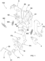
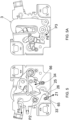
- the lock (100) comprises a base plate (6) to which a catch (1), a pawl (2) and a safety catch (3) are pivoted.
- a reset lever (4) is pivoted to the catch.
- the catch (1) and the pawl (2) are arranged in a front side of the base plate.
- the safety catch (3) and the reset lever (4) are arranged in a rear side of the base plate.
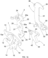
- the base plate (6) comprises a "U"-shaped slot (60) suitable for accommodating a striker pin (S) ( Fig. 2 ).
- the lock (100) can be integral with the vehicle body and the striker pin (S) can be integral with the hood lid or vice versa.
- a first pivoting pin (P1) and a second pivoting pin (P2) are arranged in respective holes (61, 62) of the base plate (6) to pivot the catch (1) around a first pivoting axis and the pawl (2) around a second pivoting axis.
- the two pivoting axes are parallel to each other and orthogonal to the base plate (6).
- a third pivoting pin (P3) is disposed in a hole (63) of the base plate (6) to pivot the safety catch (3) around a third pivoting axis.
- a fourth pivoting pin (P4) is disposed in a hole (16) of the catch and passes through a slot (64) of the base plate to pivot the reset lever (4) around a fourth pivoting axis.
- the third and fourth pivoting axes are parallel to each other and orthogonal to the base plate (6).
- a locking pin (7) is mounted in the base plate and protrudes rearwardly from the base plate, at a peripheral position with respect to the slot (64), in order to lock the reset lever (4).
- the catch (1) comprises a plate (10) with a hole (11) wherein the first pivoting pin (P1) is inserted.
- a fastening seat (12) is formed in the plate (10).
- the fastening seat (12) has a "U" shape suitable for engaging the striker pin (S) when it is in the slot (60) of the base plate, in order to close the lock as shown in Fig. 2 .
- a first stop tooth (13) is disposed above the fastening seat (12) and protrudes in upper position from the plate of the catch.
- the first stop tooth (13) has a cam surface (13a).
- a second stop tooth (14) is disposed under the fastening seat (12) and protrudes in lower position from the plate of the catch.
- a housing (15) is obtained behind the second stop tooth (14).
- the hole (16) for the fourth pivoting pin (4) is obtained in a central position of the plate of the catch. Instead, the hole (11) for the first pivoting pin (P1) is obtained in a peripheral position of the plate of the catch.
- the catch (1) can rotate around the first pivoting pin (P1) to go from a closed position ( Fig. 2 ), wherein it locks the striker pin (S), to an open position ( Fig. 6 ), wherein it releases the striker pin (S).
- An ejection spring (5) pushes the striker pin (S) so that the striker pin (S) can push the catch (1) towards the open position.
- the ejection spring (5) is arranged in the base plate (6).
- the ejection spring (5) has an arm (50) that is arranged on the slot (60) of the base plate, below the striker pin (S), so as to push the striker pin (S) outwards when it is in the slot (60) of the base plate. So, the ejection spring (5) acts as an ejector for the striker pin (S).
- the ejection spring (5) comprises a helical portion (51) connected to the arm (50), in such a way that the arm (50) tangentially protrudes from the helical portion (51).
- the helical portion (51) of the ejection spring is disposed around the first pivoting pin (P1).
- the pawl (2) comprises a plate (20) having a central hole (21) wherein the second pivoting pin (P2) is disposed, so as to generate a first arm (20a) and a second arm (20b) that extend in opposite directions.
- a first stop tooth (22) is provided on the first arm (20a) of the pawl.
- the first stop tooth (22) of the pawl is suitable for abutting against the first stop tooth (13) of the catch disposed above the fastening seat (12) of the catch in order to lock the catch (1) in closed position.
- the first stop tooth (22) of the pawl has a cam surface (22a) suitable for cooperating with the cam surface (13a) of the first stop tooth of the catch.
- a second stop tooth (23) is provided on the second arm (20b) of the pawl.
- the second stop tooth (23) of the pawl is suitable for cooperating with the second stop tooth (14) of the catch disposed below the fastening seat (12) of the catch.
- a seat (25) is provided behind the second stop tooth (23) of the pawl.
- the pawl (2) can rotate around the second pivoting pin (P2) to go from a locked position ( Fig. 1 ), wherein it locks the catch (1), to an unlocked position ( Fig. 3 ), wherein it releases the catch (1).
- the pawl (2) is stressed in the locked position by a spring (M2).
- the pawl (2) has a flange (24) disposed in the first arm (20a), behind the first stop tooth (22).
- the flange (24) is suitable for accommodating a ball of a Bowden cable connected to actuation means (not shown), such as a manually-operated actuation lever or an electrically-operated actuator.
- actuation means such as a manually-operated actuation lever or an electrically-operated actuator.
- the Bowden cable exits to the left from the base plate (6), as shown in Fig. 2 .
- the safety catch (3) has an "L"-plate shape having a first horizontal arm (30) and a second vertical arm (31).
- a hole (32) is arranged in the center of the first arm to accommodate the third pivoting pin (P3).
- a first actuation pin (33) and a second actuation pin (34) protrude orthogonally from the first arm toward the base plate (6) and are arranged in diametrically opposite positions with respect to the hole (32) of the safety catch.
- the first actuation pin (33) and the second actuation pin (34) of the safety catch (3) penetrate respective slots (65, 66) formed in the base plate (6) to protrude anteriorly from the base plate, and engage the slots (25, 15) of the pawl and of the catch, respectively.
- the slots (65, 66) of the base plate have a curved cam shape and are located on either side of the hole (63) for the third pivoting pin (P3).
- the actuation pins (33, 34) of the safety catch act as followers for the cams formed by the slots (65, 66) of the base plate.
- the safety catch (3) has a stop tooth (35) that protrudes at the end of the second arm (31) parallel to the first arm (30).
- the stop tooth (35) is disposed on the slot (60) of the base plate and is used to lock the striker pin (S).
- the safety catch (3) can be moved from a closing position ( Fig. 2A ), wherein the stop tooth (35) is disposed on the slot (10) of the base plate to lock the striker pin (S), to an open position ( Fig. 6A ), wherein the stop tooth (35) clears the slot (10) of the base plate to allow the striker pin (S) to exit.
- the safety catch (3) is stressed to the open position by a spring (M3).
- One end of the spring (M3) is connected to an attachment (36) of the safety catch, behind the stop tooth (35) and another end of the spring (M3) is connected to the base plate.
- the reset lever (4) consists in an "L"-shaped plate with a hole (41), disposed at the corner of the "L", to accommodate the fourth pivoting pin (P4) that penetrates the slot (64) of the base plate, passes through the base plate (6) and engages the center hole (16) of the catch (1).
- the reset lever (4) has a first arm (42) arranged vertically and a second arm (43) arranged horizontally.
- the reset lever (4) has a fastening seat (44) suitable for engaging the second actuation pin (34) of the safety catch (3).
- the fastening seat (44) is located at one end of the first arm of the reset lever.
- the fourth pivoting pin (P4) of the reset lever (4) can be moved in the slot (64) of the base plate, so that the reset lever (4) can be in a non-operating position ( Fig. 2A ), wherein it does not interfere with the safety catch, and in an operating position ( Fig. 6A ), wherein the fastening seat (44) of the reset lever engages the second actuation pin (34) of the safety catch.
- the second arm (43) of the reset lever is suitable for resting on the locking pin (7) to lock the reset lever in the non-operating position.
- a traction spring (M4) stresses the reset lever (4) towards the operating position. Otherwise said, the spring (M4) tends to rotate the reset lever (4) clockwise, as shown in Fig. 2A .
- a first end of the spring (M4) is connected to a protrusion (45) of the reset lever near the corner of the "L", and a second end of the spring (M4) is connected to a seat (67) of the base plate.
- the reset lever (4) rotates clockwise due to the presence of the locking pin (7) of the base plate that locks the second arm (43) of the reset lever.
- the reset lever (4) is pushed to rotate counterclockwise.
- the reset lever (4) is triggered when the second arm (43) passes the locking pin (7), that is to say only when the catch has passed an intermediate closing position (pop up) in order to fasten the safety catch (3).
- the spring (M4) also serves to rotate the safety catch (3) to its open position.
- the spring (M4) is essential for the function of the mechanism. In view of the fact that the catch (1) and the reset lever (4) assembly has two degrees of freedom, without the spring (M4) the fastening seat (44) of the reset lever might not engage the second actuation pin (34) of the safety catch.
- the lock (100) is in the fully closed position.
- the striker pin (S) is locked in the fastening seat (12) of the catch.
- the catch (1) is in closed position, blocked by the pawl (2) that is in locked position.
- the first stop tooth (22) of the pawl locks the first stop tooth (13) of the catch.
- the ejection spring (5) has its arm (50) under the striker pin (S) and pushes the striker pin (4) to eject it from the slot (60) of the base plate.
- the safety catch (3) is in closed position and the actuation pins (33, 34) of the safety catch (3) are in their respective seats (25, 15) of the pawl and of the safety catch.
- the pawl (2) holds the safety catch (3) in closed position, since the first actuation pin (33) of the safety catch is in the seat (25) of the pawl.
- the second arm (43) of the reset lever is on the locking pin (7) and therefore the reset lever (4) does not interfere with the safety catch (3).
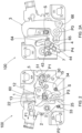
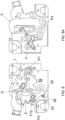
- the user performs a first actuation by pulling the Bowden cable of the pawl (2) in the direction of arrow F1.
- the pawl (2) rotates counterclockwise around the second pivoting pin (P2), going from the locked position to the unlocked position shown in Fig. 3 .
- the first stop tooth (22) of the pawl disengages the first stop tooth (13) of the catch.
- the spring (M2) of the pawl is loaded.
- the catch (1) Being disengaged from the pawl (2), the catch (1) can rotate around the first pivoting pin (P1) in the direction of the arrow F2, because of the action of the ejection spring (5) that pushes the striker pin (S), which in turn pushes the catch (1) in such a way as to partially disengage the striker pin (S) from the fastening seat (12) of the catch.
- the catch (1) prevents a rotation of the safety catch (3) to its open position.
- one end (37) of the first arm (30) of the safety catch is abutting against the first arm (42) of the reset lever so as to prevent rotation of the reset lever (4) in a counterclockwise direction with reference to Fig. 4A .
- the catch (1) is in an intermediate closing position, wherein the hood is raised to an intermediate position, the ejection spring (5) is abutting the pivoting pin (P2) of the pawl, and the preload of the ejection spring (5) is higher than the equivalent weight of the hood on the striker pin (S), in such a way that the striker pin (S) is resting on the ejection spring (5) when the catch (1) is in the intermediate closing position.
- the striker pin (S) is free to move upward, pushed by the ejection spring (5) toward the stop tooth (35) of the safety catch that is still in closed position.
- the hood is in a partially closed condition.
- the striker pin (S) can travel upwards by a few millimeters, causing the hood to lift slightly, but the striker pin (S) will still be held by the stop tooth (35) of the safety catch.
- the travel of the striker pin (S) from the intermediate closing position of the catch (1) to the stop tooth (35) of the safety catch is 15 mm.
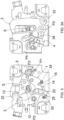
- the user actuates the Bowden cable of the pawl for the second time in the direction of the arrow F5, rotating the pawl (2) anticlockwise around the second pivoting pin (P2).
- Such a rotation of the pawl causes the first actuation pin (33) of the safety catch to disengage from the seat (25) of the pawl.
- both the first actuation pin (33) and the second actuation pin (34) of the safety catch are free.
- the safety catch (3) can rotate around the third pivoting pin (P3) in the direction of arrow F6, towards its open position because of the action of its spring (M3).
- the actuation pins (33, 34) of the safety catch are moved into the slots (65, 66) of the base plate in the direction of the arrows Z1 and Z2.
- One end (26) of the second arm (20b) of the pawl stops against the first actuation in (33) of the safety catch, preventing the pawl (2) from returning to the closed position.
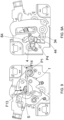
- the lock is fully open.
- the catch (1) has been rotated around the first pin (P1) in the direction of the arrow (F7) so that the striker pin (S) is completely disengaged and can be brought out of the slot (60) of the base plate.
- the movement of the catch (1) causes a movement of the reset lever (4) that is pivoted to the catch.
- the configuration of the reset lever (4) is such that, when the fastening seat (44) of the reset lever engages with the second actuation pin (34) of the safety catch in combination with the rotation of the safety catch, the second arm (43) of the reset lever no longer has the opportunity to touch the locking pin (7) of the base plate.
- the fastening seat (44) of the reset lever (4) engages the second actuation pin (34) of the safety catch (3).
- the closure of the lock is obtained thanks to the weight of the hood that pushes the striker pin (S) in the direction of the arrow F8, making the catch (1) rotate in the direction of the arrow F9 against the action of the ejection spring (5).
- the rotation of the catch (1) actuates the reset lever (4) that is moved in the direction of the arrow F10 and pulls the second actuation pin (34) of the safety catch.
- the safety catch (3) rotates in the direction of the arrow F11 and is arranged in closed position, wherein the stop tooth (35) of the safety catch closes the fastening slot (60) of the base plate.
- the first actuation pin (33) of the safety catch disengages the end (26) of the second arm (20b) of the pawl.
- the pawl (2) is free and can return to its stop position because of the action of its spring (M2).
- Such a function is essential, because if the user simply rests the lid of the hood on the vehicle body, without pushing the lid, the lock remains partially engaged because the catch (1) is in an intermediate position, but the safety catch (3) is closed, unlike the double-pull locks without safety catch of the prior art, wherein the verification of the closure of the lock is entrusted only to a microswitch.
- Fig. 8 shows the situation in which the pawl (2) has rotated in the direction of the arrow (F12), returning to its stop position, wherein the first actuation pin (33) of the safety catch is in the seat (25) of the pawl.
- Fig. 10 illustrates the situation where, as the striker pin (S) continues to be lowered for a complete closure of the lid of the hood, the cam surface (13a) of the first stop tooth (13) of the catch (1) slides over the cam surface (22a) of the first stop tooth (22) of the pawl until the first stop tooth (13) of the catch is locked by the first stop tooth (22) of the pawl, as shown in Fig. 2 .
- Fig. 10A illustrates the situation where the second arm (43) of the reset lever passes the locking pin (7) of the base plate so as to lock the reset lever in the position of Fig. 2A , wherein the reset lever does not interfere with the safety catch.
Landscapes
- Lock And Its Accessories (AREA)
Claims (10)
- Schloss (100) für Fahrzeug, umfassend:- eine Basisplatte (6) mit einem Schlitz (60), der dazu geeignet ist, einen Anschlagbolzen (S) aufzunehmen, der mit einer Karosserie oder Tür des Fahrzeugs einstückig ist,- einen Schließhaken (1) mit einem Kupplungssitz (12), der dazu geeignet ist, an dem Anschlagbolzen (S) anzukuppeln, wenn er sich in dem Schlitz (60) der Basisplatte befindet; wobei der Schließhaken (1) an der Basisplatte (6) um einen ersten Drehzapfen (P1) herum angelenkt ist, um aus einer Schließstellung, in der der Anschlagbolzen verriegelt ist, in eine Offenstellung überzugehen, in der der Anschlagbolzen entriegelt ist,- eine Auswurffeder (5) mit einem Arm (50), der auf den Anschlagbolzen (S) wirkt, um den Schließhaken (1) in die Offenstellung zu drücken,- eine Sperrklinke (2), die dazu geeignet ist, den Schließhaken (1) in der Schließstellung zu verriegeln, wobei die Sperrklinke (2) an der Basisplatte (6) um einen zweiten Drehzapfen (P2) herum angelenkt ist, um aus einer Verriegelungsstellung, in der der Schließhaken verriegelt ist, in eine Entriegelungsstellung überzugehen, in der der Schließhaken entriegelt ist; wobei die Sperrklinke (2) dazu geeignet ist, mit einem Bowdenzug verbunden zu werden, um die Sperrklinke (2) aus der Verriegelungsstellung in die Entriegelungsstellung zu bringen,- eine Feder (M2), die die Sperrklinke in die Verriegelungsstellung drückt,- einen Sicherheitshaken (3) mit einem Arretierzahn (35), der dazu geeignet ist, den Anschlagbolzen(S) in dem Schlitz (60) der Platte zu verriegeln; wobei der Sicherheitshaken (3) an der Basisplatte (6) um einen dritten Drehzapfen (P3) herum angelenkt ist, um von einer Schließstellung, in der der Anschlagbolzen verriegelt ist, in eine Offenstellung überzugehen, in der der Anschlagbolzen entriegelt ist,- eine Feder (M3), die den Sicherheitshaken in eine Offenstellung drückt,- einen Rückstellhebel (4), der an dem Schließhaken (1) um einen vierten Drehzappfen (P4) herum angelenkt ist; wobei der Rückstellhebel (4) dazu geeignet ist, sich zusammen mit dem Schließhaken (1) zu bewegen, um aus einer Ruhestellung, in der er nicht mit dem Sicherheitshaken (3) interferiert, in eine Arbeitsstellung überzugehen, in der er an den Sicherheitshaken (3) ankuppelt, und- eine Feder (M4), die den Rückstellhebel (4) in die Arbeitsstellung drückt.
- Schloss (100) nach Anspruch 1, wobei der Rückstellhebel (4) so konfiguriert ist, dass:- er an den Sicherheitshaken (3) ankuppelt, wenn der Sicherheitshaken (3) sich in der Offenstellung befindet und die Tür des Fahrzeugs geschlossen wird, so dass der Schließhaken (1) aufgrund des Gewichts der Tür in die Schließstellung bewegt wird,- er den Sicherheitshaken (3) in die Schließstellung mitzieht, wenn der Schließhaken (1) in seine Schließstellung bewegt wird, und- er den Sicherheitshaken (3) freigibt, wenn der Schließhaken (1) in der Schließstellung angekommen ist.
- Schloss (100) nach Anspruch 1 oder 2, wobei der Schließhaken (1) eine Platte (20) mit einem Loch (16) für den vierten Drehzapfen (4) umfasst, der in einer zentralen Stellung der Platte herausgearbeitet ist, und mit einem Loch (11) für den ersten Drehzapfen (P1), der in einer peripheren Stellung der Platte herausgearbeitet ist.
- Schloss (100) nach einem der vorstehenden Ansprüche, wobei der Schließhaken (1) und die Sperrklinke (2) vorn an der Basisplatte (6) angeordnet sind und wobei der Sicherheitshaken (3) und der Rückstellhebel hinten an der Basisplatte angeordnet sind;
wobei die Basisplatte (6) einen Schlitz (64) aufweist, durch den der vierte Drehzapfen (P4) hindurchgeht. - Schloss (100) nach Anspruch 4, wobei der Sicherheitshaken (3) wie eine L-förmige Platte geformt ist, mit einem ersten Arm (30), einem zweiten Arm (31), und einem Loch (32), das im Mittelpunkt des ersten Armes angeordnet ist, um den dritten Drehzapfen (P3) aufzunehmen;wobei ein erster Betätigungsstift (33) und ein zweiter Betätigungsstift (34) rechtwinklig aus dem ersten Arm zu der Basisplatte (6) hin vorstehen und in diametral gegenüberliegenden Stellungen in Bezug auf das Loch (32) des Sicherheitshakens angeordnet sind;wobei der erste Betätigungsstift (33) und der zweite Betätigungsstift (34) des Sicherheitshakens (3) in jeweilige Schlitze (65, 66) einfallen, die in der Basisplatte (6) herausgearbeitet sind, um vorn aus der Basisplatte vorzustehen und Sitze (25, 15) in der Sperrklinke bzw. in dem Schließhaken in Eingriff zu nehmen.
- Schloss (100) nach Anspruch 5, wobei der Rückstellhebel (4) einen Kupplungssitz (44) umfasst, der dazu geeignet ist, an den zweiten Betätigungsstift (34) des Sicherheitshakens (3) anzukuppeln.
- Schloss (100) nach Anspruch 6, wobei der Rückstellhebel (4) eine L-förmige Form aufweist, wobei der vierte Zapfen (P4) in der Ecke des "L" angeordnet ist und einen ersten Arm (42) mit dem Kupplungssitz (44) definiert, und einen zweiten Arm (43), der dazu geeignet ist, auf einem Verriegelungsstift (7) der Basisplatte einzurasten, wenn der Rückstellhebel (4) sich in Ruhestellung befindet.
- Schloss (100) nach Anspruch 7, wobei die Schlitze (65, 66) der Basisplatte eine kurvenförmige Form aufweisen und auf beiden Seiten in Bezug auf ein Loch (63) der Basisplatte angeordnet sind, das den dritten Drehzapfen (P3) aufnimmt.
- Schloss (100) nach einem der vorstehenden Ansprüche, wobei der Schließhaken (1) umfasst:- einen ersten Arretierzahn (13), der über dem Kupplungssitz (12) angeordnet ist und oben aus der Platte des Schließhakens vorsteht, und- einen zweiten Arretierzahn (14), der unter dem Kupplungssitz (12) angeordnet ist und unten aus der Platte des Schließhakens vorsteht; und
wobei die Sperrklinke (2) umfasst:- eine Platte (20) mit einem zentralen Loch (21), wobei der zweite Drehzapfen (P2) so angeordnet ist, dass er einen ersten Arm (20a) und einen zweiten Arm (20b) erzeugt, die sich in entgegengesetzte Richtungen erstrecken,- einen ersten Arretierzahn (22), der auf dem ersten Arm (20a) der Sperrklinke vorgesehen ist und dazu geeignet ist, gegen den ersten Arretierzahn (13) des Schließhakens in Anschlag zu gehen, um den Schließhaken (1) in Schließstellung zu verriegeln, und- einen zweiten Arretierzahn (23), der auf dem zweiten Arm (20b) der Sperrklinke vorgesehen ist und dazu geeignet ist, mit dem zweiten Arretierzahn (14) des Schließhakens zusammenzuwirken. - Schloss (100) nach Anspruch 9, wobei der erste Arretierzahn (13) des Schließhakens eine Kurvenfläche (13a) aufweist und der erste Arretierzahn (22) der Sperrklinke eine Kurvenfläche (22a) aufweist, die dazu geeignet ist, mit der Kurvenfläche (13a) des ersten Arretierzahn des Schließhakens zusammenzuwirken.
Applications Claiming Priority (2)
| Application Number | Priority Date | Filing Date | Title |
|---|---|---|---|
| IT202000024787 | 2020-10-20 | ||
| PCT/EP2021/078823 WO2022084257A1 (en) | 2020-10-20 | 2021-10-18 | Double-pull vehicle lock with safety catch |
Publications (3)
| Publication Number | Publication Date |
|---|---|
| EP4232664A1 EP4232664A1 (de) | 2023-08-30 |
| EP4232664C0 EP4232664C0 (de) | 2024-08-14 |
| EP4232664B1 true EP4232664B1 (de) | 2024-08-14 |
Family
ID=74068580
Family Applications (1)
| Application Number | Title | Priority Date | Filing Date |
|---|---|---|---|
| EP21794549.2A Active EP4232664B1 (de) | 2020-10-20 | 2021-10-18 | Doppelzug-fahrzeugschloss mit sicherheitsverriegelung |
Country Status (2)
| Country | Link |
|---|---|
| EP (1) | EP4232664B1 (de) |
| WO (1) | WO2022084257A1 (de) |
Families Citing this family (2)
| Publication number | Priority date | Publication date | Assignee | Title |
|---|---|---|---|---|
| CN114961455B (zh) * | 2022-05-27 | 2023-07-21 | 伟速达(中国)汽车安全系统有限公司 | 具有电动开启和电动吸合功能的前盖锁 |
| EP4682337A1 (de) | 2024-07-17 | 2026-01-21 | CEBI ITALY S.p.A. | Doppelzugschloss mit sicherheitsverriegelung für eine fahrzeughaube |
Family Cites Families (4)
| Publication number | Priority date | Publication date | Assignee | Title |
|---|---|---|---|---|
| AU6767298A (en) * | 1997-04-08 | 1998-10-30 | Dura Automotive Systems, Inc. | Dual release hood latch and handle and system for operation |
| DE102010025355B4 (de) * | 2010-06-28 | 2014-11-13 | Audi Ag | Schlossvorrichtung für ein Kraftfahrzeug |
| US8419114B2 (en) | 2011-08-30 | 2013-04-16 | GM Global Technology Operations LLC | Dual action hood latch assembly for a vehicle |
| US10590683B2 (en) * | 2015-06-15 | 2020-03-17 | Magna Closures Inc. | Vehicle hood latch and method of unlatching a vehicle hood |
-
2021
- 2021-10-18 EP EP21794549.2A patent/EP4232664B1/de active Active
- 2021-10-18 WO PCT/EP2021/078823 patent/WO2022084257A1/en not_active Ceased
Also Published As
| Publication number | Publication date |
|---|---|
| EP4232664A1 (de) | 2023-08-30 |
| EP4232664C0 (de) | 2024-08-14 |
| WO2022084257A1 (en) | 2022-04-28 |
Similar Documents
| Publication | Publication Date | Title |
|---|---|---|
| EP4077841B1 (de) | Doppelzugschloss für fahrzeuge | |
| US11421454B2 (en) | Closure latch assembly with latch mechanism and outside release mechanism having reset device | |
| US11933086B2 (en) | Double pull latch for closure panel such as hood | |
| US11377881B2 (en) | Lock for motor vehicle hood | |
| US9388610B2 (en) | Door latch assembly of vehicle | |
| US5423582A (en) | Power-assist motor-vehicle door latch | |
| JP6155488B2 (ja) | 複数パーツを備えた爪部を有するロック装置 | |
| US5803515A (en) | Vehicle door latch | |
| CN105074106B (zh) | 用于机动车的锁 | |
| US20120161456A1 (en) | Locking device for an automobile | |
| CN111663864B (zh) | 用于车辆的电机驱动的车门锁闩 | |
| EP4232664B1 (de) | Doppelzug-fahrzeugschloss mit sicherheitsverriegelung | |
| US6575506B2 (en) | Door lock system for vehicle | |
| EP1084918A1 (de) | Verschluss | |
| US11111703B2 (en) | Hood latch apparatus for vehicle | |
| CN114382358A (zh) | 用于机动车辆应用的车罩和前行李箱的双拉闭合闩锁组件 | |
| JPH11513764A (ja) | 車両のドアラッチ組立体 | |
| EP1179108B1 (de) | Verschluss | |
| CN115126356B (zh) | 车辆用锁定装置 | |
| WO2014195928A1 (en) | Inside door handle with locking function using single cable | |
| US20260022593A1 (en) | Double-pull lock with safety catch for a vehicle hood | |
| KR20240161437A (ko) | 전동 도어 래치 | |
| JP2000345748A (ja) | 内側から解放可能な車両用トランクリッドラッチ機構及びその解放方法 | |
| JPH0988397A (ja) | キャビネットにおける跳上げ扉の安全係止装置 | |
| WO2020230017A1 (en) | Closure latch assembly for motor vehicles having crash safety mechanism with inertia lever |
Legal Events
| Date | Code | Title | Description |
|---|---|---|---|
| STAA | Information on the status of an ep patent application or granted ep patent |
Free format text: STATUS: UNKNOWN |
|
| STAA | Information on the status of an ep patent application or granted ep patent |
Free format text: STATUS: THE INTERNATIONAL PUBLICATION HAS BEEN MADE |
|
| PUAI | Public reference made under article 153(3) epc to a published international application that has entered the european phase |
Free format text: ORIGINAL CODE: 0009012 |
|
| STAA | Information on the status of an ep patent application or granted ep patent |
Free format text: STATUS: REQUEST FOR EXAMINATION WAS MADE |
|
| 17P | Request for examination filed |
Effective date: 20230309 |
|
| AK | Designated contracting states |
Kind code of ref document: A1 Designated state(s): AL AT BE BG CH CY CZ DE DK EE ES FI FR GB GR HR HU IE IS IT LI LT LU LV MC MK MT NL NO PL PT RO RS SE SI SK SM TR |
|
| DAV | Request for validation of the european patent (deleted) | ||
| DAX | Request for extension of the european patent (deleted) | ||
| GRAP | Despatch of communication of intention to grant a patent |
Free format text: ORIGINAL CODE: EPIDOSNIGR1 |
|
| STAA | Information on the status of an ep patent application or granted ep patent |
Free format text: STATUS: GRANT OF PATENT IS INTENDED |
|
| INTG | Intention to grant announced |
Effective date: 20240521 |
|
| GRAS | Grant fee paid |
Free format text: ORIGINAL CODE: EPIDOSNIGR3 |
|
| GRAA | (expected) grant |
Free format text: ORIGINAL CODE: 0009210 |
|
| STAA | Information on the status of an ep patent application or granted ep patent |
Free format text: STATUS: THE PATENT HAS BEEN GRANTED |
|
| AK | Designated contracting states |
Kind code of ref document: B1 Designated state(s): AL AT BE BG CH CY CZ DE DK EE ES FI FR GB GR HR HU IE IS IT LI LT LU LV MC MK MT NL NO PL PT RO RS SE SI SK SM TR |
|
| REG | Reference to a national code |
Ref country code: GB Ref legal event code: FG4D |
|
| REG | Reference to a national code |
Ref country code: CH Ref legal event code: EP |
|
| REG | Reference to a national code |
Ref country code: DE Ref legal event code: R096 Ref document number: 602021017304 Country of ref document: DE |
|
| REG | Reference to a national code |
Ref country code: IE Ref legal event code: FG4D |
|
| U01 | Request for unitary effect filed |
Effective date: 20240910 |
|
| U07 | Unitary effect registered |
Designated state(s): AT BE BG DE DK EE FI FR IT LT LU LV MT NL PT RO SE SI Effective date: 20240925 |
|
| U20 | Renewal fee for the european patent with unitary effect paid |
Year of fee payment: 4 Effective date: 20241025 |
|
| PG25 | Lapsed in a contracting state [announced via postgrant information from national office to epo] |
Ref country code: NO Free format text: LAPSE BECAUSE OF FAILURE TO SUBMIT A TRANSLATION OF THE DESCRIPTION OR TO PAY THE FEE WITHIN THE PRESCRIBED TIME-LIMIT Effective date: 20241114 |
|
| PG25 | Lapsed in a contracting state [announced via postgrant information from national office to epo] |
Ref country code: GR Free format text: LAPSE BECAUSE OF FAILURE TO SUBMIT A TRANSLATION OF THE DESCRIPTION OR TO PAY THE FEE WITHIN THE PRESCRIBED TIME-LIMIT Effective date: 20241115 Ref country code: PL Free format text: LAPSE BECAUSE OF FAILURE TO SUBMIT A TRANSLATION OF THE DESCRIPTION OR TO PAY THE FEE WITHIN THE PRESCRIBED TIME-LIMIT Effective date: 20240814 |
|
| PG25 | Lapsed in a contracting state [announced via postgrant information from national office to epo] |
Ref country code: IS Free format text: LAPSE BECAUSE OF FAILURE TO SUBMIT A TRANSLATION OF THE DESCRIPTION OR TO PAY THE FEE WITHIN THE PRESCRIBED TIME-LIMIT Effective date: 20241214 |
|
| PG25 | Lapsed in a contracting state [announced via postgrant information from national office to epo] |
Ref country code: HR Free format text: LAPSE BECAUSE OF FAILURE TO SUBMIT A TRANSLATION OF THE DESCRIPTION OR TO PAY THE FEE WITHIN THE PRESCRIBED TIME-LIMIT Effective date: 20240814 |
|
| PG25 | Lapsed in a contracting state [announced via postgrant information from national office to epo] |
Ref country code: ES Free format text: LAPSE BECAUSE OF FAILURE TO SUBMIT A TRANSLATION OF THE DESCRIPTION OR TO PAY THE FEE WITHIN THE PRESCRIBED TIME-LIMIT Effective date: 20240814 Ref country code: RS Free format text: LAPSE BECAUSE OF FAILURE TO SUBMIT A TRANSLATION OF THE DESCRIPTION OR TO PAY THE FEE WITHIN THE PRESCRIBED TIME-LIMIT Effective date: 20241114 |
|
| PG25 | Lapsed in a contracting state [announced via postgrant information from national office to epo] |
Ref country code: RS Free format text: LAPSE BECAUSE OF FAILURE TO SUBMIT A TRANSLATION OF THE DESCRIPTION OR TO PAY THE FEE WITHIN THE PRESCRIBED TIME-LIMIT Effective date: 20241114 Ref country code: PL Free format text: LAPSE BECAUSE OF FAILURE TO SUBMIT A TRANSLATION OF THE DESCRIPTION OR TO PAY THE FEE WITHIN THE PRESCRIBED TIME-LIMIT Effective date: 20240814 Ref country code: NO Free format text: LAPSE BECAUSE OF FAILURE TO SUBMIT A TRANSLATION OF THE DESCRIPTION OR TO PAY THE FEE WITHIN THE PRESCRIBED TIME-LIMIT Effective date: 20241114 Ref country code: IS Free format text: LAPSE BECAUSE OF FAILURE TO SUBMIT A TRANSLATION OF THE DESCRIPTION OR TO PAY THE FEE WITHIN THE PRESCRIBED TIME-LIMIT Effective date: 20241214 Ref country code: HR Free format text: LAPSE BECAUSE OF FAILURE TO SUBMIT A TRANSLATION OF THE DESCRIPTION OR TO PAY THE FEE WITHIN THE PRESCRIBED TIME-LIMIT Effective date: 20240814 Ref country code: GR Free format text: LAPSE BECAUSE OF FAILURE TO SUBMIT A TRANSLATION OF THE DESCRIPTION OR TO PAY THE FEE WITHIN THE PRESCRIBED TIME-LIMIT Effective date: 20241115 Ref country code: ES Free format text: LAPSE BECAUSE OF FAILURE TO SUBMIT A TRANSLATION OF THE DESCRIPTION OR TO PAY THE FEE WITHIN THE PRESCRIBED TIME-LIMIT Effective date: 20240814 |
|
| PG25 | Lapsed in a contracting state [announced via postgrant information from national office to epo] |
Ref country code: SM Free format text: LAPSE BECAUSE OF FAILURE TO SUBMIT A TRANSLATION OF THE DESCRIPTION OR TO PAY THE FEE WITHIN THE PRESCRIBED TIME-LIMIT Effective date: 20240814 |
|
| PG25 | Lapsed in a contracting state [announced via postgrant information from national office to epo] |
Ref country code: CZ Free format text: LAPSE BECAUSE OF FAILURE TO SUBMIT A TRANSLATION OF THE DESCRIPTION OR TO PAY THE FEE WITHIN THE PRESCRIBED TIME-LIMIT Effective date: 20240814 |
|
| PG25 | Lapsed in a contracting state [announced via postgrant information from national office to epo] |
Ref country code: SK Free format text: LAPSE BECAUSE OF FAILURE TO SUBMIT A TRANSLATION OF THE DESCRIPTION OR TO PAY THE FEE WITHIN THE PRESCRIBED TIME-LIMIT Effective date: 20240814 |
|
| REG | Reference to a national code |
Ref country code: CH Ref legal event code: PL |
|
| PLBE | No opposition filed within time limit |
Free format text: ORIGINAL CODE: 0009261 |
|
| STAA | Information on the status of an ep patent application or granted ep patent |
Free format text: STATUS: NO OPPOSITION FILED WITHIN TIME LIMIT |
|
| PG25 | Lapsed in a contracting state [announced via postgrant information from national office to epo] |
Ref country code: MC Free format text: LAPSE BECAUSE OF FAILURE TO SUBMIT A TRANSLATION OF THE DESCRIPTION OR TO PAY THE FEE WITHIN THE PRESCRIBED TIME-LIMIT Effective date: 20240814 |
|
| 26N | No opposition filed |
Effective date: 20250515 |
|
| PG25 | Lapsed in a contracting state [announced via postgrant information from national office to epo] |
Ref country code: CH Free format text: LAPSE BECAUSE OF NON-PAYMENT OF DUE FEES Effective date: 20241031 |
|
| U20 | Renewal fee for the european patent with unitary effect paid |
Year of fee payment: 5 Effective date: 20250818 |
|
| PG25 | Lapsed in a contracting state [announced via postgrant information from national office to epo] |
Ref country code: IE Free format text: LAPSE BECAUSE OF NON-PAYMENT OF DUE FEES Effective date: 20241018 |
|
| PG25 | Lapsed in a contracting state [announced via postgrant information from national office to epo] |
Ref country code: CY Free format text: LAPSE BECAUSE OF FAILURE TO SUBMIT A TRANSLATION OF THE DESCRIPTION OR TO PAY THE FEE WITHIN THE PRESCRIBED TIME-LIMIT; INVALID AB INITIO Effective date: 20211018 |
|
| PG25 | Lapsed in a contracting state [announced via postgrant information from national office to epo] |
Ref country code: HU Free format text: LAPSE BECAUSE OF FAILURE TO SUBMIT A TRANSLATION OF THE DESCRIPTION OR TO PAY THE FEE WITHIN THE PRESCRIBED TIME-LIMIT; INVALID AB INITIO Effective date: 20211018 |