EP4232256B1 - Extrusions- und/oder pultrusionsvorrichtung und -verfahren - Google Patents
Extrusions- und/oder pultrusionsvorrichtung und -verfahren Download PDFInfo
- Publication number
- EP4232256B1 EP4232256B1 EP21794121.0A EP21794121A EP4232256B1 EP 4232256 B1 EP4232256 B1 EP 4232256B1 EP 21794121 A EP21794121 A EP 21794121A EP 4232256 B1 EP4232256 B1 EP 4232256B1
- Authority
- EP
- European Patent Office
- Prior art keywords
- channel section
- rotating die
- profile
- section
- channel
- Prior art date
- Legal status (The legal status is an assumption and is not a legal conclusion. Google has not performed a legal analysis and makes no representation as to the accuracy of the status listed.)
- Active
Links
Images


Classifications
-
- B—PERFORMING OPERATIONS; TRANSPORTING
- B29—WORKING OF PLASTICS; WORKING OF SUBSTANCES IN A PLASTIC STATE IN GENERAL
- B29C—SHAPING OR JOINING OF PLASTICS; SHAPING OF MATERIAL IN A PLASTIC STATE, NOT OTHERWISE PROVIDED FOR; AFTER-TREATMENT OF THE SHAPED PRODUCTS, e.g. REPAIRING
- B29C43/00—Compression moulding, i.e. applying external pressure to flow the moulding material; Apparatus therefor
- B29C43/32—Component parts, details or accessories; Auxiliary operations
- B29C43/44—Compression means for making articles of indefinite length
- B29C43/46—Rollers
-
- B—PERFORMING OPERATIONS; TRANSPORTING
- B21—MECHANICAL METAL-WORKING WITHOUT ESSENTIALLY REMOVING MATERIAL; PUNCHING METAL
- B21C—MANUFACTURE OF METAL SHEETS, WIRE, RODS, TUBES, PROFILES OR LIKE SEMI-MANUFACTURED PRODUCTS OTHERWISE THAN BY ROLLING; AUXILIARY OPERATIONS USED IN CONNECTION WITH METAL-WORKING WITHOUT ESSENTIALLY REMOVING MATERIAL
- B21C23/00—Extruding metal; Impact extrusion
- B21C23/02—Making uncoated products
- B21C23/04—Making uncoated products by direct extrusion
- B21C23/14—Making other products
- B21C23/142—Making profiles
-
- B—PERFORMING OPERATIONS; TRANSPORTING
- B21—MECHANICAL METAL-WORKING WITHOUT ESSENTIALLY REMOVING MATERIAL; PUNCHING METAL
- B21C—MANUFACTURE OF METAL SHEETS, WIRE, RODS, TUBES, PROFILES OR LIKE SEMI-MANUFACTURED PRODUCTS OTHERWISE THAN BY ROLLING; AUXILIARY OPERATIONS USED IN CONNECTION WITH METAL-WORKING WITHOUT ESSENTIALLY REMOVING MATERIAL
- B21C25/00—Profiling tools for metal extruding
- B21C25/02—Dies
-
- B—PERFORMING OPERATIONS; TRANSPORTING
- B21—MECHANICAL METAL-WORKING WITHOUT ESSENTIALLY REMOVING MATERIAL; PUNCHING METAL
- B21C—MANUFACTURE OF METAL SHEETS, WIRE, RODS, TUBES, PROFILES OR LIKE SEMI-MANUFACTURED PRODUCTS OTHERWISE THAN BY ROLLING; AUXILIARY OPERATIONS USED IN CONNECTION WITH METAL-WORKING WITHOUT ESSENTIALLY REMOVING MATERIAL
- B21C35/00—Removing work or waste from extruding presses; Drawing-off extruded work; Cleaning dies, ducts, containers, or mandrels for metal extruding
- B21C35/02—Removing or drawing-off work
- B21C35/023—Work treatment directly following extrusion, e.g. further deformation or surface treatment
-
- B—PERFORMING OPERATIONS; TRANSPORTING
- B29—WORKING OF PLASTICS; WORKING OF SUBSTANCES IN A PLASTIC STATE IN GENERAL
- B29C—SHAPING OR JOINING OF PLASTICS; SHAPING OF MATERIAL IN A PLASTIC STATE, NOT OTHERWISE PROVIDED FOR; AFTER-TREATMENT OF THE SHAPED PRODUCTS, e.g. REPAIRING
- B29C43/00—Compression moulding, i.e. applying external pressure to flow the moulding material; Apparatus therefor
- B29C43/32—Component parts, details or accessories; Auxiliary operations
- B29C43/34—Feeding the material to the mould or the compression means
-
- B—PERFORMING OPERATIONS; TRANSPORTING
- B29—WORKING OF PLASTICS; WORKING OF SUBSTANCES IN A PLASTIC STATE IN GENERAL
- B29C—SHAPING OR JOINING OF PLASTICS; SHAPING OF MATERIAL IN A PLASTIC STATE, NOT OTHERWISE PROVIDED FOR; AFTER-TREATMENT OF THE SHAPED PRODUCTS, e.g. REPAIRING
- B29C48/00—Extrusion moulding, i.e. expressing the moulding material through a die or nozzle which imparts the desired form; Apparatus therefor
- B29C48/001—Combinations of extrusion moulding with other shaping operations
- B29C48/0011—Combinations of extrusion moulding with other shaping operations combined with compression moulding
-
- B—PERFORMING OPERATIONS; TRANSPORTING
- B29—WORKING OF PLASTICS; WORKING OF SUBSTANCES IN A PLASTIC STATE IN GENERAL
- B29C—SHAPING OR JOINING OF PLASTICS; SHAPING OF MATERIAL IN A PLASTIC STATE, NOT OTHERWISE PROVIDED FOR; AFTER-TREATMENT OF THE SHAPED PRODUCTS, e.g. REPAIRING
- B29C48/00—Extrusion moulding, i.e. expressing the moulding material through a die or nozzle which imparts the desired form; Apparatus therefor
- B29C48/001—Combinations of extrusion moulding with other shaping operations
- B29C48/0018—Combinations of extrusion moulding with other shaping operations combined with shaping by orienting, stretching or shrinking, e.g. film blowing
-
- B—PERFORMING OPERATIONS; TRANSPORTING
- B29—WORKING OF PLASTICS; WORKING OF SUBSTANCES IN A PLASTIC STATE IN GENERAL
- B29C—SHAPING OR JOINING OF PLASTICS; SHAPING OF MATERIAL IN A PLASTIC STATE, NOT OTHERWISE PROVIDED FOR; AFTER-TREATMENT OF THE SHAPED PRODUCTS, e.g. REPAIRING
- B29C48/00—Extrusion moulding, i.e. expressing the moulding material through a die or nozzle which imparts the desired form; Apparatus therefor
- B29C48/03—Extrusion moulding, i.e. expressing the moulding material through a die or nozzle which imparts the desired form; Apparatus therefor characterised by the shape of the extruded material at extrusion
- B29C48/12—Articles with an irregular circumference when viewed in cross-section, e.g. window profiles
-
- B—PERFORMING OPERATIONS; TRANSPORTING
- B29—WORKING OF PLASTICS; WORKING OF SUBSTANCES IN A PLASTIC STATE IN GENERAL
- B29C—SHAPING OR JOINING OF PLASTICS; SHAPING OF MATERIAL IN A PLASTIC STATE, NOT OTHERWISE PROVIDED FOR; AFTER-TREATMENT OF THE SHAPED PRODUCTS, e.g. REPAIRING
- B29C48/00—Extrusion moulding, i.e. expressing the moulding material through a die or nozzle which imparts the desired form; Apparatus therefor
- B29C48/16—Articles comprising two or more components, e.g. co-extruded layers
- B29C48/18—Articles comprising two or more components, e.g. co-extruded layers the components being layers
- B29C48/21—Articles comprising two or more components, e.g. co-extruded layers the components being layers the layers being joined at their surfaces
-
- B—PERFORMING OPERATIONS; TRANSPORTING
- B29—WORKING OF PLASTICS; WORKING OF SUBSTANCES IN A PLASTIC STATE IN GENERAL
- B29C—SHAPING OR JOINING OF PLASTICS; SHAPING OF MATERIAL IN A PLASTIC STATE, NOT OTHERWISE PROVIDED FOR; AFTER-TREATMENT OF THE SHAPED PRODUCTS, e.g. REPAIRING
- B29C48/00—Extrusion moulding, i.e. expressing the moulding material through a die or nozzle which imparts the desired form; Apparatus therefor
- B29C48/25—Component parts, details or accessories; Auxiliary operations
- B29C48/30—Extrusion nozzles or dies
- B29C48/35—Extrusion nozzles or dies with rollers
-
- B—PERFORMING OPERATIONS; TRANSPORTING
- B29—WORKING OF PLASTICS; WORKING OF SUBSTANCES IN A PLASTIC STATE IN GENERAL
- B29C—SHAPING OR JOINING OF PLASTICS; SHAPING OF MATERIAL IN A PLASTIC STATE, NOT OTHERWISE PROVIDED FOR; AFTER-TREATMENT OF THE SHAPED PRODUCTS, e.g. REPAIRING
- B29C48/00—Extrusion moulding, i.e. expressing the moulding material through a die or nozzle which imparts the desired form; Apparatus therefor
- B29C48/25—Component parts, details or accessories; Auxiliary operations
- B29C48/88—Thermal treatment of the stream of extruded material, e.g. cooling
- B29C48/911—Cooling
-
- B—PERFORMING OPERATIONS; TRANSPORTING
- B29—WORKING OF PLASTICS; WORKING OF SUBSTANCES IN A PLASTIC STATE IN GENERAL
- B29C—SHAPING OR JOINING OF PLASTICS; SHAPING OF MATERIAL IN A PLASTIC STATE, NOT OTHERWISE PROVIDED FOR; AFTER-TREATMENT OF THE SHAPED PRODUCTS, e.g. REPAIRING
- B29C70/00—Shaping composites, i.e. plastics material comprising reinforcements, fillers or preformed parts, e.g. inserts
- B29C70/04—Shaping composites, i.e. plastics material comprising reinforcements, fillers or preformed parts, e.g. inserts comprising reinforcements only, e.g. self-reinforcing plastics
- B29C70/28—Shaping operations therefor
- B29C70/40—Shaping or impregnating by compression not applied
- B29C70/50—Shaping or impregnating by compression not applied for producing articles of indefinite length, e.g. prepregs, sheet moulding compounds [SMC] or cross moulding compounds [XMC]
- B29C70/52—Pultrusion, i.e. forming and compressing by continuously pulling through a die
- B29C70/525—Component parts, details or accessories; Auxiliary operations
- B29C70/526—Pultrusion dies, e.g. dies with moving or rotating parts
-
- B—PERFORMING OPERATIONS; TRANSPORTING
- B29—WORKING OF PLASTICS; WORKING OF SUBSTANCES IN A PLASTIC STATE IN GENERAL
- B29C—SHAPING OR JOINING OF PLASTICS; SHAPING OF MATERIAL IN A PLASTIC STATE, NOT OTHERWISE PROVIDED FOR; AFTER-TREATMENT OF THE SHAPED PRODUCTS, e.g. REPAIRING
- B29C43/00—Compression moulding, i.e. applying external pressure to flow the moulding material; Apparatus therefor
- B29C43/32—Component parts, details or accessories; Auxiliary operations
- B29C43/44—Compression means for making articles of indefinite length
- B29C43/46—Rollers
- B29C2043/461—Rollers the rollers having specific surface features
- B29C2043/463—Rollers the rollers having specific surface features corrugated, patterned or embossed surface
-
- B—PERFORMING OPERATIONS; TRANSPORTING
- B29—WORKING OF PLASTICS; WORKING OF SUBSTANCES IN A PLASTIC STATE IN GENERAL
- B29C—SHAPING OR JOINING OF PLASTICS; SHAPING OF MATERIAL IN A PLASTIC STATE, NOT OTHERWISE PROVIDED FOR; AFTER-TREATMENT OF THE SHAPED PRODUCTS, e.g. REPAIRING
- B29C43/00—Compression moulding, i.e. applying external pressure to flow the moulding material; Apparatus therefor
- B29C43/32—Component parts, details or accessories; Auxiliary operations
- B29C43/44—Compression means for making articles of indefinite length
- B29C43/46—Rollers
- B29C2043/461—Rollers the rollers having specific surface features
- B29C2043/465—Rollers the rollers having specific surface features having one or more cavities, e.g. for forming distinct products
-
- B—PERFORMING OPERATIONS; TRANSPORTING
- B29—WORKING OF PLASTICS; WORKING OF SUBSTANCES IN A PLASTIC STATE IN GENERAL
- B29C—SHAPING OR JOINING OF PLASTICS; SHAPING OF MATERIAL IN A PLASTIC STATE, NOT OTHERWISE PROVIDED FOR; AFTER-TREATMENT OF THE SHAPED PRODUCTS, e.g. REPAIRING
- B29C48/00—Extrusion moulding, i.e. expressing the moulding material through a die or nozzle which imparts the desired form; Apparatus therefor
- B29C48/15—Extrusion moulding, i.e. expressing the moulding material through a die or nozzle which imparts the desired form; Apparatus therefor incorporating preformed parts or layers, e.g. extrusion moulding around inserts
- B29C48/154—Coating solid articles, i.e. non-hollow articles
-
- B—PERFORMING OPERATIONS; TRANSPORTING
- B29—WORKING OF PLASTICS; WORKING OF SUBSTANCES IN A PLASTIC STATE IN GENERAL
- B29C—SHAPING OR JOINING OF PLASTICS; SHAPING OF MATERIAL IN A PLASTIC STATE, NOT OTHERWISE PROVIDED FOR; AFTER-TREATMENT OF THE SHAPED PRODUCTS, e.g. REPAIRING
- B29C48/00—Extrusion moulding, i.e. expressing the moulding material through a die or nozzle which imparts the desired form; Apparatus therefor
- B29C48/25—Component parts, details or accessories; Auxiliary operations
- B29C48/30—Extrusion nozzles or dies
- B29C48/32—Extrusion nozzles or dies with annular openings, e.g. for forming tubular articles
- B29C48/34—Cross-head annular extrusion nozzles, i.e. for simultaneously receiving moulding material and the preform to be coated
-
- B—PERFORMING OPERATIONS; TRANSPORTING
- B29—WORKING OF PLASTICS; WORKING OF SUBSTANCES IN A PLASTIC STATE IN GENERAL
- B29C—SHAPING OR JOINING OF PLASTICS; SHAPING OF MATERIAL IN A PLASTIC STATE, NOT OTHERWISE PROVIDED FOR; AFTER-TREATMENT OF THE SHAPED PRODUCTS, e.g. REPAIRING
- B29C48/00—Extrusion moulding, i.e. expressing the moulding material through a die or nozzle which imparts the desired form; Apparatus therefor
- B29C48/25—Component parts, details or accessories; Auxiliary operations
- B29C48/36—Means for plasticising or homogenising the moulding material or forcing it through the nozzle or die
- B29C48/49—Means for plasticising or homogenising the moulding material or forcing it through the nozzle or die using two or more extruders to feed one die or nozzle
-
- B—PERFORMING OPERATIONS; TRANSPORTING
- B29—WORKING OF PLASTICS; WORKING OF SUBSTANCES IN A PLASTIC STATE IN GENERAL
- B29C—SHAPING OR JOINING OF PLASTICS; SHAPING OF MATERIAL IN A PLASTIC STATE, NOT OTHERWISE PROVIDED FOR; AFTER-TREATMENT OF THE SHAPED PRODUCTS, e.g. REPAIRING
- B29C55/00—Shaping by stretching, e.g. drawing through a die; Apparatus therefor
- B29C55/30—Drawing through a die
-
- B—PERFORMING OPERATIONS; TRANSPORTING
- B29—WORKING OF PLASTICS; WORKING OF SUBSTANCES IN A PLASTIC STATE IN GENERAL
- B29L—INDEXING SCHEME ASSOCIATED WITH SUBCLASS B29C, RELATING TO PARTICULAR ARTICLES
- B29L2031/00—Other particular articles
- B29L2031/001—Profiled members, e.g. beams, sections
- B29L2031/003—Profiled members, e.g. beams, sections having a profiled transverse cross-section
Definitions
- the invention relates to an extrusion and/or pultrusion device for forming a profile product made from a viscoelastic material and/or plastically deformable material with elastic property and/or viscoplastic material with elastic property in a production direction, said device comprising:
- the invention also relates to a method for producing a profile product by use of such a device.
- the load rate of the material in the first channel is controlled with reference to the load rate in the second channel by design of the respective first channel and second channel.
- the claimed device comprises both static and moving part and operates at high production rate and high pressure, and sometimes under high temperature and pressure.
- the settings for the device is dependent on material and type of profile to be produced. Experiments performed during a long time span has revealed that materials made from a viscoelastic material and/or plastically deformable material with elastic property and/or viscoplastic material with elastic property have special features/properties that have to be taken into account in order to produce a profile product with high quality in the claimed device and at the same time design the device in a way to make it withstand the high forces during operation.
- the following definitions are introduced in order to give a reader information on suitable such materials and settings of the device.
- plastic deformable materials deform permanently when subjected to a sufficiently high force. Permanent deformation is generally referred to as plastic deformation and materials which exhibit this type of deformation may therefore be denominated "plastically deformable materials".
- the deformation behaviour in a plastic deformable material depends on the magnitude of the force that the material is subject to and is often described in so called “stress-strain curves”. Generally, plastically deformable material exhibit the following deformation behaviour.
- the material When the material is subjected to a small force it deforms elastically because the stress in the material increases the distance between the atoms in the material but does not affect their mutual arrangement. Therefore, the material reverts linearly to its original dimension when the force is removed. Thus, in this force region the material exhibits a linearly elastic deformation behaviour.
- Viscoplasticity is a theory that describes materials which behave as solids below a critical values of stress but flows like a viscous liquid at greater values of stress.
- viscoplasticity is the macroscopic behavior caused by a mechanism linked to the movement of dislocations in grains, with superposed effects of intercrystalline gliding. The mechanism usually becomes dominant at temperatures greater than approximately one third of the absolute melting temperature. Thus, these materials become viscoplastic materials above this critical temperature.
- a main difference of viscoplastic materials in comparison to non-viscoplastic material is that the viscoplastic material exhibit a rate-dependent deformation behavior in force region of plastic deformation. That is, the viscoplastic-material does not only deform permanently after the application of the force but continue to undergo a creep flow as a function of time under the influence of the applied force. This creep flow deforms the material further.
- Viscous materials like glycerine, oil or water, resist shear flow and strain linearly with time when a stress is applied. In pure viscous fluids, deformation is non-recoverable due to rearrangement of molecules. Elastic materials strain when stretched and immediately return to their original state once the stress is removed.
- a material is said to be viscoelastic if the material has an elastic (recoverable) part as well as a viscous (nonrecoverable) part.
- the elastic deformation is instantaneous while deformation of the viscous part occurs over time.
- Viscoelastic materials have elements of both elastic (recoverable) character viscous (nonrecoverable) character it is said to exhibit time-dependent strain, i.e. it deforms over time by so called creep. Viscoelastic materials may also be strain rate-dependent, i.e. they deform differently depending on how fast the load is applied.
- viscoelastic materials are polymers, their viscoelastic behaviour may be explained by entanglement and disentanglement processes on a molecular level of polymer chains.
- the present invention relates to a device that extrudes and/or pultrudes a material that undergoes a recoverable, i.e. elastic, transitions springing back from a deformed state to a less deformed state.
- a recoverable i.e. elastic
- a non-exhaustive list of examples of such materials are; rubber, elastomers, composites and polymers, etc.
- the invention relates to an extrusion and/or pultrusion device for forming a profile product made from a viscoelastic material and/or plastically deformable material with elastic property and/or viscoplastic material with elastic property in a production direction, said device comprising:
- the first channel section is configured to deform the material into a master profile having a maximum height at a predetermined feeding rate dependent on material and minimum cross-sectional area with a first maximum height in the first channel section when exiting the first channel section,
- One advantage here is that maximum allowable pressure is controlled in both the firstand second channel which gives the possibility to design the extrusion and/or pultrusion device dependent on material to be processed and process speed. Controlling the maximum allowable pressure dependent on material to be processed allows for a production rate with high quality output and reduces risk for e.g. rupture due to a too high stress on the material and further reduces risk for damaging the device.
- a further advantage is that the wake element can be designed dependent on material elasticity giving the correct height of the master profile when entering the second channel section.
- elasticity refers to the material swelling after having been pressed into shape in the first channel section.
- the wake element creates a wave form in the material when having passed the wake element.
- the wake element protrudes in a direction from the side wall into the first channel section. According to one example, the wake element protrudes in the height direction from the side wall into the first channel section
- the wake element is arranged where the first channel section transitions into the second channel section, wherein the wake element comprises an upper edge with a lowest part, in the height direction, wherein the upper edge delimits an upper portion, in the height direction, of the wake element in the first channel section where the first channel section transitions into the second channel section.
- the wake element controls the master profile cross-section area in close vicinity to the rotating die. Different materials have different elastic properties and thus partly recovers shape, i.e. swells, after the wake element at different rates.
- the wake element is arranged at a predetermined distance upstream in the production direction from where the first channel section transitions into the second channel section.
- the wake element controls the master profile cross-section area before where the first channel section transitions into the second channel section, which allows for the material to recover shape after the wake element but still in the second channel section thus controlling the shape of the master profile immediately before entering the second channel section.
- Different materials have different elastic properties and thus partly recovers shape, i.e. swells, after the wake element at different rates. Some materials need a series of portions recovering shape in order to finally stay in its desired form in the profile product.
- the master profile height when exiting the first channel section is less than or equal to the master profile height in the second channel section before reaching the rotating die due to elasticity.
- the position of the wake element determines where and how the master profile is allowed to recover shape and the closer the wake element is to the where the rotating die has its minimum distance to the counter-bearing, the less possibility for the master profile to recover its shape in the second channel section.
- the first channel section comprises at least two side walls in the form of a top pre-bearing and an opposing bottom pre-bearing, wherein the top pre-bearing is arranged over the opposing bottom pre-bearing in the height direction, wherein the top pre-bearing and/or the bottom pre-bearing comprises the wake element.
- the rotating die has a lowest position in the height direction at a position where the distance in the height direction between the circumferential surface and the counter-bearing is at a minimum, and the lowest position of the rotting die can be arranged below or above or at equal level as the lowest part of the upper edge of the wake element. It is a design feature determined by the elastic property of the material.
- the rotating die comprises a pattern comprising at least one indentation, wherein the rotating die is configured at a maximum distance between a bottom of the indentation and the counter-bearing dependent on a minimum allowable pressure applied by the rotating die at the position of that maximum distance for achieving plastic deformation of the material in the indentation.
- the pattern in the rotating die causes a corresponding opposite pattern in the final profile, i.e. when the pattern in the rotating die comprises an indentation, it causes a corresponding opposite pattern comprising an elevation in the in the final profile.
- the rotating die is thus configured at a maximum distance between the rotating die and the counter-bearing dependent on a minimum allowable pressure applied by the rotating die at the position of that minimum distance, wherein the minimum allowable pressure corresponds to the difference in height of the master profile and the final profile and dependent on pattern in the circumferential surface of the rotating die with regard to achieving the plastic deformation desired in the indentation, which minimum pressure depends on the material to be extruded and/or pultruded.
- the pattern in the rotating die could be arranged such that the device simultaneously exhibits the minimum distance and the maximum distance if the pattern is arranged such that the indentation is positioned in the circumferential surface with surrounding portion(s) of the circumferential surface, at least in the width direction, comprising no indentations when facing the counter-bearing.
- the pattern comprises a number of indentations spread in the width direction with such non-indentation portions between them facing the counter-bearing at the same time.
- the rotating die exerts both maximum pressure in the non-indentation portion due to the minimum distance and minimum pressure in the indentation due to the minimum distance, at least during a short time interval during rotation of the rotating die.
- the design choice of maximum pressure and minimum pressure further allows for an optimized form change of the master profile to the final profile dependent on material such that the material in the indentation fills the indentation and becomes deformed at the same time as the material between the outermost parts, in the radial direction, of the rotating die does not exceed the maximum pressure allowed for the material and/or the design of the extrusion and/or pultrusion device.
- some materials exhibit properties that allows for easy filling of the indentations due to the initial pressure difference between the inside and the outside of the indentation.
- a steady state condition with regard to pressure difference, is achieved during a short time period. In such steady state condition the pressure in the material is balanced and the pressure difference is minimized.
- the pressure could be equal or essentially equal in both the indentation and the surrounding non-indentation part during that part of the operation when the indentation faces the counter bearing and the indentation is filled.
- a minimum pressure is required to achieve plastic deformation.
- aluminium has a minimum pressure level that depends on inter alia temperature and the higher the temperature the less pressure is required.
- a too high pressure and thus a too high temperature may result in the aluminium liquifying which removes the advantage of plastic deformation.
- the temperature increase in the material is at least in part achieved in the first channel section where the minimum cross-sectional area forces a form change of the material with pressure on the material in all directions in the first channel section and the form change increase the temperature.
- the rotating die continues to change the shape of the master profile into the final profile by exerting a balanced pressure within the minimum and maximum limits.
- the minimum pressure is also vital for filling the indentations in a manner with sufficient pressure to achieve plastic deformation within the indentation.
- that part of the rotating die lacking indentations exerts a higher pressure on the master profile due to a lesser distance between the rotating die and the counter-bearing than between the bottom of the indentation and the counter-bearing.
- both the minimum pressure and the maximum pressure becomes especially important and thus the respective maximum and minimum distance between the rotating die and the counter-bearing.
- a cylindrical coordinate system has been used for the rotating die and an orthogonal Cartesian coordinate system for a three-dimensional space for the device in general.
- the rotating die therefore is described as having a width direction from end to end coinciding with a centre line, i.e. rotation axis, about which the rotating die rotates, and a thickness in a radial direction being orthogonal to the width direction.
- the outer circumferential surface further extends about the axis in a rotation direction being perpendicular to the width direction.
- rotation symmetric refers to a symmetrical disposition about the rotating axis or a rotational balanced disposition of the matter in the rotating die.
- the device in general i.e. e.g. the profile definition zone, the first and second channel sections, is described as having a width direction, a height direction and a longitudinal direction, where the longitudinal direction coincides with the general production direction.
- the rotating die is arranged to be rotatable about the axis and the axis can be directly or indirectly stored in and rotatably coupled to the first and second channel portion side walls.
- the axis of the rotating die can be arranged perpendicular to the longitudinal direction, i.e. to the production direction of the device in general, or can be arranged at an angle.
- the axis of the rotating die is directed substantially perpendicular to the production direction with the outer circumferential surface extending across the production direction in a width direction thereof.
- the axis of the rotating die coincides with the width direction of the device in general and the width direction of the rotating die coincide with the width direction of the device in general.
- the longitudinal direction coincides with the production direction, i.e. the main direction along which the material travels during production.
- the axis of the rotating die does not coincide with the width direction of the device in general, but the axis of the rotating die and the width direction of the rotating die is arranged at an angle being less or more than 90° to the longitudinal direction.
- the axis of the rotating die is arranged such that the outer circumferential surface extends across the production direction in a width direction thereof.
- the normal to the axis of the rotating die coincides with the height direction of the device in general.
- the normal coincides with the radial direction of the rotating die.
- the axis of the rotating die is directed perpendicular to the normal of the production direction regardless of whether the axis of the rotating die coincide or not with the width direction of the device in general.
- the normal to the axis of the rotating die can be arranged at an angle to the height direction of the device in general.
- the axis of the rotating die is arranged such that the outer circumferential surface extends across the production direction in a width direction thereof, but at an angle to the production direction.
- the one or more walls define a first cross-section at the end of the first channel section and wherein the second channel section defines a second cross-section at a position where the distance between the circumferential surface and the counter-bearing is at a minimum.
- the geometry of the first channel section is different from the second channel section such that the material passing through the first channel section changes form when entering the second channel section.
- the changing of form is essential for increasing or maintaining the pressure level to such an extent that it will overcome the internal resistance (shear stresses) of the material, fast enough, for the material to saturate the second cross section, including an imprint of the rotating die.
- the minimum distance in the height direction between the circumferential surface and the counter-bearing in the second cross-section is less than a maximum distance in the height direction in the first cross-section.
- the pressure is increased or maintained to such level that the material will transform fast enough to saturate the second channel section, including an imprint of the rotating die.
- the pressure is achieved by a combination of an imprint depth of a pattern in the circumferential surface and a Poisson effect and/or a combination of the shape transition due to the geometrical shape difference between the first and second crosssections and the Poisson effect.
- the geometry of the first channel section is different from the second channel section such that the material passing through the first channel section changes form when entering the second channel section
- the master profile has a first cross-section area geometry corresponding to the first cross-section and wherein the final profile has a second cross-section area geometry defined by the second cross-section, wherein the first cross-section area geometry is different from the second cross-section area geometry in any given comparable position, wherein the maximum pressure and thus the minimum distance in the second channel section is dependent on a difference of cross-section area geometry of the master profile and the cross-section area geometry of the final profile.
- the rotating die is configured, before forming the profile product, to alter form during forming of the final profile dependent on the maximum allowable pressure and/or, wherein the counter-bearing is configured, before forming the profile product, to alter form during forming of the profile product dependent on the maximum allowable pressure.
- the rotating die can be configured to change shape from a start-up procedure to steady state operation conditions due to heat and pressure during the production, giving a predicted shape of the final profile.
- the counter-bearing can be configured to change shape due to heat and pressure during the production, giving a predicted shape of the final profile in a similar manner.
- the first channel section comprises side walls in the form of a top pre-bearing and an opposing bottom pre-bearing.
- the top pre-bearing is arranged over the opposing bottom pre-bearing in the height direction and are advantageously positioned in or at least in the vicinity of where the first channel section transitions into the second channel section.
- One advantage here is that the top pre-bearing and/or the bottom pre-bearing can be optimised to release a certain master profile cross-section geometry into the second channel section.
- top pre-bearing and/or the bottom pre-bearing can be configured in a similar manner as the rotating die and/or the counter-bearing to change form from a start-up procedure to a steady state operation
- the maximum pressure and thus the minimum distance in the second channel section is dependent on the total feeding rate of material in the first channel section, type of material, and temperature of the material when entering the second channel section.
- the maximum allowable pressure applied by the rotating die at the position of the minimum distance is dependent on friction between the material and the counter bearing in the second channel section.
- the cross-section area of the second channel section is configured to be sized with regard to a shrinking effect of the final profile cooling down to the profile product having a final height.
- the pattern in the rotating die is configured to be sized with regard to a shrinking effect of the final profile cooling down to the profile product.
- the rotating die is configured with a pattern with at least one indentation, wherein each indentation comprises a release angle dependent on the radius of the rotating die, the intended pattern in the final profile, the configuration of the counter bearing and travelling speed of the final profile in order to achieve the intended profile product.
- the release angle in the indentation is arranged with relation to a release angle in a corresponding elevation created in the final profile due to the material being pressed into the cavity. Since the rotating die rotates, the indentation can be arranged with a shape that is different from the shape in the profile product taking into account the rotation and release angles affect the shape of the elevation in the final profile when the elevation is released from the indentation in the production direction.
- the device is configured to feed a friction material between the counter-bearing and the final profile and/or configured to feed a friction material between the rotating die and the final profile.
- the friction sheet can be used to define and therefore predict friction between the material in any of the first and/or second channels sections.
- the friction material can be a solid, liquid or gas and can be introduced into the device in nay suitable way.
- the friction material can be introduced by feeding the material to the rotating die and/or the counter-bearing via a separate channel arranged in connection to the first channel section and/or the second channel section.
- the friction material can alternatively be introduced to the rotating die before the rotating die rotates into the second channel section, i.e.
- the friction material travels along with the rotating die to the material in the second channels section.
- the friction material can alternatively be introduced to the material before entering the first channel section, i.e. the friction material travels with the material to be extruded and/or pultruded.
- the friction material be a solid, it could be introduced as a sheet material or any suitable form that allows for the friction sheet to define friction between the material in any of the first and/or second channels sections.
- the friction material be a liquid, it can be introduced by dripping or injecting the liquid according to any one or a combination of the examples above, but is not limited to the examples.
- the friction material be a gas
- it can be introduced by injecting the gas according to any one or a combination of the examples above, but is not limited to the examples.
- the material that is fed into the device to form the profile product can be in the form of one homogenous material or a mixture of two or more materials that are blended and or layered.
- the materials can be blended in different ratios and may be blended into a homogeneous mix or a mix with gradients within the material.
- One material can be a solid and another material can be mouldable, e.g. stone bits and rubber.
- the material can also be a layered material comprising two or more layers of same or different materials.
- the material may comprise one or more strings of solid material that follow through the entire extrusion or pultrusion process, e.g. a wire or another reinforcement material.
- the width of the first channel section is, at least along a portion of its length and at least along a portion of its height, less than a distance between the two opposite side walls of the rotating die.
- the first channel section should be at least smaller in width than a distance between the opposing first and second channel portion side walls in the second channel section.
- the difference in width between the first channel section and the second channel section depends on features of the first and second side portions and tolerances between the rotating die and the respective opposing first and second channel portion side walls.
- the width of the first channel section should be less than a distance being the distance between the opposing first and second channel portion side walls minus the sum of tolerances, i.e.
- the width of the first channel section is, at least along a portion of its length and at least along a portion of its height, less than a distance between the two flange portions.
- One advantage here is that local pressure reduction is achieved in connection to the first and second outer edge portions due to the geometrical difference in the first and second channel sections.
- local pressure reduction is achieved in connection to the first and/or second side portions due to the geometrical difference in the first and second channel sections and a wake effect downstream the first channel section in connection to the first and/or second side portions.
- the first channel section comprises a third side portion extending in the width direction, wherein the third side portion is arranged in relation to the first side portion such that a pressure in the material to be extruded is less in connection to the first side portion than in connection to the third side portion, and/or wherein the first channel section comprises a fourth side portion extending in the width direction, wherein the fourth side portion is arranged in relation to the second side portion such that a pressure in the material to be extruded is less in connection to the second side portion than in connection to the fourth side portion.
- third and fourth side portions creates a wake effect and thus a local pressure decrease downstream the third and fourth side portions that further decreases the local pressure in the first and second side portions of the rotating die.
- the first channel section comprises leeward means in connection to the third and/or fourth side portions arranged to decrease the space of the first channel section in the height direction being perpendicular to the width direction.
- the first channel section comprises leeward means in connection to the third and/or fourth side portions arranged to decrease the space of the first channel section in the width direction.
- leeward means are also possible.
- the leeward means is an elevation facing into the through channel.
- the elevation can be arranged from top to bottom in the first channel section, or can be arranged as a part or several parts along the distance between the top to bottom of the first channel section.
- the leeward means are advantageously positioned in connection to the first and second side portions of the rotating die.
- the third and fourth side portions further decreases the local pressure in connection to recesses and/or flange portions in the first and second side portions of the rotating die, see below.
- the second channel section is arranged in relation to the first channel section with a predetermined second distance between the radially outermost portion of the circumferential surface of the rotating die and the counter-bearing in the channel portion being less than a predetermined first distance between the most far apart portions of the first channel section taken in a height direction coinciding with the radial direction, and/or wherein: the second channel section is arranged in relation to the first channel section with a predetermined fourth distance between the innermost narrowest portions of the channel portion in the width direction being greater than a predetermined third distance between side walls in the first channel section taken in the width direction at the exit area from the first channel section.
- the narrower first channel section creates a wake effect with decreased pressure downstream in the first channel section and in connection to the first and second side portions of the rotating die due to that the second channels section is broader.
- the circumferential surface comprises a textured portion.
- the entire circumferential surface can be textured, but as an alternative only a portion can be textured.
- the circumferential surface is non-textured or has a micro pattern that leaves only an infinitesimal imprint on the profile product that can be visible or non-visible for the human eye.
- the channel portion comprises a second rotating die arranged opposite the first rotating die described above.
- the second rotating die can either replace the counter-bearing in its entirety or can be a part of a static counter-bearing.
- the second rotating die can be arranged in a similar way as the above described first rotating die to create same or different patterns on two sides of the profile product.
- the second rotating die can comprise recesses and/or flange portions that can be arranged to cooperate with recesses and/or flange portions of the first rotating die.
- the channel portion comprises a third rotating die arranged at an angle to the first rotating die.
- This rotating die replaces the opposing first or second channel portion side wall entirely or partly.
- the third rotating die can be arranged together with only the first rotating die or together with both the first and second rotating die.
- the channel portion comprises a fourth rotating die arranged opposite the third rotating die.
- the third rotating die can be arranged together with only the first rotating die or together with both the first and second rotating die
- the third and/or the fourth rotating die(s) can be arranged in a similar way as the above described first rotating die to create same or different patterns on two sides of the profile product.
- the second rotating die can comprise recesses and/or flange portions that can be arranged to cooperate with recesses and/or flange portions of the first rotating die.
- two or more rotating dies are synchronised. This has the advantage of feeding the material at the same speed.
- non-synchronous rotating dies in order to create friction and/or a special pattern and/or to compensate for material differences, or to achieve curved profiles, that follows a radius instead of a straight line at exit of the rotating die.
- the invention also refers to a method for producing a profile product by use of a device according to any one of the preceding claims, wherein the method comprises
- the final profile and/or the profile product is stretched for achieving the same distance in the pattern along the production direction, i.e. to achieve equal distance between elevations and/or indentations in the pattern along the production direction.
- the distance between indentations in the pattern on the rotating die is less than a distance between indentations in the corresponding pattern in the production direction on the profile product, wherein a pulling and stretching device is configured to stretch the final profile and/or the profile product so that high precision in distance between features on profile can be achieved by adjustment stretching
- At least a part of the material should be plastically deformable when subject to the pressure applied in the first and/or second channel sections.
- Such materials are often denoted viscoelastic and/or viscoplastic materials.
- extrusion relates to a process where a material is fed by pressure into the first channel section to be formed in the first and second channel sections.
- Pultrusion relates to where the material to be formed is fed to the device and drawn through the first and second channel sections. It should be noted that the device can be arranged purely for extrusion or purely for pultrusion or a combination of the two.
- profile product refers to a product having a three dimensional form, i.e. length, width and height.
- the profile product may have a cross-section taken in the width and height plane being similar all along the length or may be different dependent on position in length.
- the cross-section can have any suitable two dimensional shape, for example, round, oval, elliptical, i.e. two sides, undulating, three or more sides or a combination of the same.
- One or more sides may be patterned, i.e. textured with one or more patterns.
- the pattem/texture is created by the rotating die.
- the first channel section could be circumferentially delimited by static walls or could be arranged with one or more dynamic walls as long as the material can be extruded or pultruded with the device according to the invention.
- Static walls has the advantage of being cheap and robust.
- the first channel portions can be arranged centred with relation to the second channels. This has the advantage that the flow of material entering the second channel is evenly distributed.
- the first and second side portions can be arranged centred with respect to the first channel section with the advantage of having a evenly distributed decrease in pressure over the rotating die.
- the device could comprise several rotating devices arranged side by side, i.e. the rotating device could comprise two or more rotating devices having a common rotating axel.
- the different rotating devices could be arranged in separate second channels or could be arranged in a common separate channel.
- the different rotating devices could have the same or different texture to create same or different patterns on the profile product.
- the profile product could thus comprise one or more strands of internal profiles running along the production direction and being generated by the different rotating devices.
- the different strands could be separable into separate products at predetermined separation lines that could coincide with the separation of the different rotating devices.
- one separate rotating die could comprise a pattern/texture that separates similar or different patterns such that the profiled product comprises one or more strands of internal profiles running along the production direction.
- the strands could be separable in the profiled product.
- the rotating die and/or the counter-bearing comprises a cooling device that cools down the material when forming the final profile.
- a cooling device that cools down the material when forming the final profile.
- the cooling device can, for example, be arranged in the form of cooling circuits with gas or liquid fluid conductors arranged within the rotating die and/or the counter-bearing; and/or external devices cooling down the rotating die and/or the counter-bearing; and/or liquids or gaseous fluids added to the rotating die and/or the counter-bearing; or a combination of such devices or any other suitable cooling devices.
- the rotating die is configured to be cooled on the surface so that the temperature of the rotating die surface is below a predetermined allowed temperature of the extruded material.
- the rotating die is cooled on the surface so that the temperature of the rotating die surface is at least 10 degrees Celsius below a glass transition temperature or melting temperature of the material.
- the rotating die is cooled on the surface so that the temperature of the rotating die surface is at least 50 degrees Celsius below a glass transition temperature or melting temperature of the material, enabling higher speed of extruding.
- the device can further be arranged for co-extrusion and/or on-extrusion with one or more inlet channels that connects to the first channel section.
- one or more materials could be fed to the first channel section via one channel, but two or more materials can be fed to the first channel section via one inlet channel or a multiple channel inlets.
- the multiple inlet channels can be the same in number as the number of materials or the multiple inlet channels can be less than the number of materials if two or more materials are fed via one inlet channel.
- Two or more materials can be fed to the first channel section and/or the second channel section via one inlet channel or multiple channel inlets.
- the multiple inlet channels can be the same or more in number as the number of materials or the multiple inlet channels can be less than the number of materials if two or more materials are fed via one inlet channel.
- the invention further relates to a co-extrusion device and/or an on-extrusion device comprising an extrusion and/or pultrusion device according to what has been described above.
- the co-extrusion device and/or an on-extrusion device comprises at least two inlet channels that connects directly or indirectly to the second channel section, wherein each of the at least two inlet channels is configured to feed one or more materials at a predetermined distance upstream from the second channel section or to a marriage point for the at least two inlet channels in connection to where the first channel section transitions into the second channel section.
- co-extrusion and/or on-extrusion allows for manufacturing a layered profile product and/or a profile product with different materials and/or a profile product with a core embedded in a surrounding material, e.g. electrical wire, toothed belt etc.
- the device comprises a pulling and stretching device arranged downstream the second channel section and configured to pull the material in the production direction when exiting the second channel section for transforming the final profile to the profile product.
- the distance between indentations in the pattern on the rotating die is less than a distance between elevations in the corresponding pattern in the production direction on the profile product, wherein the pulling and stretching device is configured to stretch the final profile and/or the profile product so that high precision in distance between features on profile can be achieved by adjustment stretching.
- the distance between the indentations in the rotating die is taken in the rotation direction, i.e. along the circumferential surface in the rotation direction.
- the pulling and stretching device dynamically can stretch the material in the final profile during its transition to profile product, e.g. in order to obtain an equidistant pattern in the production direction of the profile product.
- the pulling and stretching device can further be used to guide the final product in the width and/or height direction during its transition from final product to profile product in order to control bending.
- the pulling and stretching device can be any type of device that comprises means for gripping the material and means for pulling.
- the pulling and stretching device comprises controlling means for controlling the pulling force applied to the material.
- the controlling means may comprise sensor(s) and/or may be connected to sensor(s) that supervises the state of the final profile and/or the material during its transition from the final profile to the profile product.
- the sensor(s) comprises means for sending analog and/or digital information to the controlling means.
- the information relates to the state of the material and the controlling means are configured to process the information for controlling the pulling and stretching device.
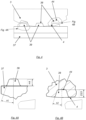
- front view with inlet and back view with outlet are used as an orientation for the reader with regard to production direction where material to be worked is inserted into the inlet and a profile product is shaped in the device and then exits the device via the outlet.
- the production direction is denoted PD with an arrow pointing in the production direction.
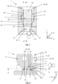
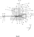
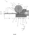
- FIG. 1 schematically shows a view from below along section A-A in figure 2 , i.e. in a height direction Z, of a device according to one example of the invention and figure 2 schematically shows a cross-section perspective view of the device in figure 1.
- Figures 1 and 2 show an extrusion- or pultrusion device 1 for extrusion- or pultrusion in a production direction Y of a profile product 2 , see figures 2A-2I and figs 4, 4A, 4B , 7 and 8 , made from a viscoelastic material and/or plastically deformable material with elastic property and/or viscoplastic material with elastic property.
- the device comprises:
- figures 1, 2 , 2A-2D schematically show that the first channel section 9 is configured to deform the material into a master profile 36 having a maximum height H1 at a predetermined feeding rate dependent on material and minimum cross-sectional area with a first maximum height D1 in the first channel section 9 when exiting the first channel section,
- the first channel section 9 comprises at least two side walls 11 in the form of a top pre-bearing 41 and an opposing bottom pre-bearing 42, wherein the top pre-bearing 41 is arranged over the opposing bottom pre-bearing 42 in the height direction Z, wherein the top pre-bearing 41 and/or the bottom pre-bearing 42 comprises the wake element 58.
- the wake element protrudes in a direction from the side wall into the first channel section. According to one example, the wake element protrudes in the height direction from the side wall into the first channel section
- One advantage here is that maximum load is controlled in both the first- and second channel section which gives the possibility to design the extrusion and/or pultrusion device dependent on material to be processed and process speed. Controlling the maximum load dependent on material to be processed allows for a production rate with high quality output and reduces risk for e.g. rupture due to a too high stress on the material.
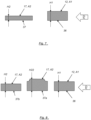
- Figure 2A schematically shows a similar view as figure 2 and that the material is formed in the first channel section 9 into the master profile 36 and directly thereafter formed in the second channel section 10 into the final profile 37.
- Figure 2A also shows that the final profile 37 has a lesser height H1 than the height H2 of the master profile 36 due to further pressure on the master profile 36 in the second channel section 10.
- Figure 2A also shows that the product profile 2 has a lesser height H3 than the height H1 of the final profile 36 due to shrinking when cooling down from the final profile 37 to the product profile 2.
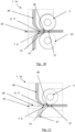
- the rotating die lacks indentions 38 as shown in figures 2B-2D .
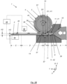
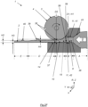
- Figure 2B schematically shows a side view along cross-section B-B in figure 1 and is similar to figure 2A , but the rotating device is rotated such that the part of the rotating die 3 pressing against the material against the counter-bearing 14 does not comprise an indentation 38.
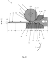
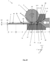
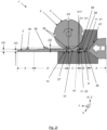
- Figures 2C and 2D show a similar device 1 as figure 2B , but where the rotating die 3 is rotated such that the indentation 38 with a bottom 44 faces the counter bearing14.
- Figure 2B schematically shows an initial zone A where the material is pressed by a device (not shown) into the first channel section 9 either by a device (not shown) exerting an external pressure in the production direction, i.e. extrusion, and/or by the material being dragged through the first channel 9 by a device (not shown) dragging the material in the production direction PD, i.e. pultrusion.
- Zone A of the device comprises a funnel shaped opening 43 where the material changes form from an initial form having a larger cross-section that the first channel section 9.
- the shape of the opening can, however, vary depending on material, temperature and device pressing the material.
- Figure 2B schematically shows a zone B arranged directly after zone A, wherein zone B correspond to the first channel section 9 and where the formation of the master profile 36 takes place due to the material changing form due to the pressure exerted on the material from the side walls 11 in the first channel section 9 when the material moves through the first channel section 9.
- Figure 2B schematically shows a zone C arranged directly after zone B, wherein zone C correspond to the second channel section 10 and where the formation of the final profile 36 takes place due to the material changing form due to the pressure exerted on the material from at least the rotating die 3 and the opposing counter bearing 14 in the second channel section 10 when the material moves through the second channel section 9.
- Figure 2B schematically shows a zone D arranged directly after zone C, wherein zone D correspond to a section of the production line after the second channel section 10 and where the material starts to cool down and where the final profile 36 starts to change form due to shrinking as a consequence of the temperature drop.
- zone D the final profile 37 can be subject to various production measures for achieving desired material properties. For example, cooling, heating, stretching, compressing, etc. in order to change the final profile 37 into a profile product 2 with desired material properties.
- Zone D depends on material properties and a working environment surrounding the material in zone D.
- the material properties are e.g. heat dissipation and the mass of the material to be cooled down. For example, a thinner material cools down faster than a thicker material.
- the working environment refers e.g. to ambient temperature and humidity. For example, a warmer environment slows down the cooling process compared to a cooler environment.
- Figure 2B schematically shows a zone E arranged after zone D, wherein zone E correspond to a section of the production line where the material has cooled down to a predetermined temperature representing a temperature establishing the final form of the product profile and where no or an infinitesimal change of form will continue.
- Figure 2B shows that the profile product has a height H3 in Zone E being less than the height H2 of the final profile 37.
- the pattern 39 of the final profile 37 has shrunk to a pattern 40 in zone E due to the cooling.
- Figure 2B shows an example, where the device 1 according to any of the examples above comprises a pulling and stretching device 54 arranged downstream the second channel section 10 and configured to pull the material in the production direction PD when exiting the second channel section 10 for transforming the final profile 37 to the profile product 2.
- a pulling and stretching device 54 arranged downstream the second channel section 10 and configured to pull the material in the production direction PD when exiting the second channel section 10 for transforming the final profile 37 to the profile product 2.
- the pulling and stretching device dynamically can stretch the material in the final profile during its transition to profile product, e.g. in order to obtain an equidistant pattern in the production direction of the profile product.
- the pulling and stretching device can further be used to guide the final product in the width and/or height direction during its transition from to final product to profile product in order to control bending.
- the distance between indentations 38 in the pattern 38 on the rotating die 3 is less than a distance between elevations 40 in the corresponding pattern 38 in the production direction on the profile product 2, wherein the pulling and stretching device 54 is configured to stretch the final profile 37 and/or the profile product 2 so that high precision in distance between features on profile can be achieved by adjustment stretching.
- the pulling and stretching device can be any type of device that comprises means for gripping the material and means for pulling.
- the pulling and stretching device comprises controlling means 55 for controlling the pulling force applied to the material.
- the controlling means 55 may comprise sensor(s) and/or may be connected to sensor(s) 56 that supervises the state of the final profile and/or the material during its transition from the final profile to the profile product.
- the sensor(s) comprises means for sending analog and/or digital information to the controlling means.
- the information relates to the state of the material and the controlling means is configured to process the information for controlling the pulling and stretching device.
- the rotating die 3 and/or the counter-bearing 14 comprises a cooling device 57 that cools down the material when forming the final profile 37.
- the cooling device can, for example, be arranged in the form of cooling circuits with gas or liquid fluid conductors arranged within the rotating die and/or the counter-bearing; and/or external devices cooling down the rotating die and/or the counter-bearing; and/or liquids or gaseous fluids added to the rotating die and/or the counter-bearing; or a combination of such devices or any other suitable cooling devices.
- rotating die 3 can be configured to operate without the cooling device 57 in figure 2B , as is shown in e.g. figs. 2C-2D .
- the rotating die 3 is configured to be cooled on the surface so that the temperature of the rotating die surface is below a predetermined allowed temperature of the extruded material.
- the rotating die is cooled on the surface so that the temperature of the rotating die surface is at least 10 degrees Celsius below a glass transition temperature or melting temperature of the material.
- the rotating die is cooled on the surface so that the temperature of the rotating die surface is at least 50 degrees Celsius below a glass transition temperature or melting temperature of the material, enabling higher speed of extruding.
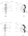
- Figures 2B-2D schematically show that the rotating die 3 comprises a pattern 38 comprising at least one indentation 38 in the circumferential surface 4.
- the pattern 38 comprises 4 indentations, but the number of indentations is here only an illustrative example and there may be more or less indentation in a pattern spread over the rotating die in a predetermined design depending on the desired features of the profile product 2.
- the indentations can have any shape suitable, for example oval, round, polygon or a mixture of such or other shapes.
- the indentations 38 have a bottom 44 at a maximum depth of the indentation and the indentations may have different or similar depths.
- the rotating die comprises portions that have a minimum distance D2 between the rotating die 3 and the counter bearing 14 when facing the counter-bearing 14.
- the indentation 38 with the largest distance between the bottom 44 and the counter-bearing 14 when facing the counter-bearing forms a maximum distance D22, see figures 2C and 2D , between the rotating die 3 and the counter-bearing 14.
- the minimum distance D2 in the height direction Z between the circumferential surface 4 and the counter-bearing 14 in the second cross-section 17 is less than a maximum distance D1 in the height direction in the first cross-section 12.
- Figures 2C and 2D schematically shows the same side view as figure 2B with Zones as described above, but with the rotating die 3 being rotated such that one indentation 38 faces the counter-bearing 14.
- Figures 2C and 2D schematically show that the rotating die 3 is configured at a maximum distance D22 between a bottom 44 of the indentation 38 and the counter-bearing 14 dependent on a minimum allowable pressure applied by the rotating die at the position of that maximum distance D22 for achieving plastic deformation of the material in the indentation 38.
- Figures 2B-2D schematically shows that, the pattern 38 in the rotating die 3 is configured to be sized with regard to a shrinking effect of the final profile 37 cooling down to the profile product 2.
- the pattern 38 in the rotating 3 could be arranged such that the device 1 simultaneously exhibits the minimum distance D2 and the maximum distance D22 if the pattern 38 is arranged such that the indentation is positioned in the circumferential surface 4 with surrounding portion(s) of the circumferential surface 4, at least in the width direction X, comprising no indentations when facing the counter-bearing 14.
- the pattern 38 comprises a number of indentations 38 spread in the width direction X with such non-indentation portions between them facing the counter-bearing 14 at the same time.
- the rotating die 3 exerts both maximum pressure in the non-indentation portion due to the minimum distance D2 and minimum pressure in the indentation due to the minimum distance D22 during at least a short time interval.
- the design choice of maximum pressure and minimum pressure further allows for an optimized form change of the master profile to the final profile dependent on material such that the material in the indentation fills the indentation and becomes deformed at the same time as the material between the outermost parts, in the radial direction, of the rotating die does not exceed the maximum pressure allowed for the material and/or the design of the extrusion and/or pultrusion device. It should further be noted that some materials exhibit properties that allows for easy filling of the indentations due to the initial pressure difference between the inside and the outside of the indentation.
- the rotating die can have a different circumferential distance between the indentations 38 than what is given in the finished profile product should it be rolled up around the rotating die, allowing for compensation and adjusting distance between features to get high precision on finished profile product by e.g. stretching the final profile after extrusion.
- Figure 2C schematically shows that an upper portion 41, also called pre-bearing 41 below, of the wall 11 in the first channel section 9 is arranged at a height level in the Z-direction above a maximum height level of the bottom 44 of the indentation 38 when the indentation 38 faces the counter-bearing 14.
- Figure 2D schematically shows that the upper portion 41 of the wall 11 in the first channel section 9 is arranged at a height level in the Z-direction below a maximum height level of the bottom 44 of the indentation 38 when the indentation 38 faces the counter-bearing 14.
- the height level of the upper portion 41 can vary dependent on material and on the pattern 38 in the rotating die 3 and thus how the material changes form to fill the indentation 38 with the plastic deformation.
- Figures 2A to 2I schematically show that the first channel section 9 comprises side walls 11 in the form of a top pre-bearing 41 and an opposing bottom pre-bearing 42.
- the top pre-bearing 41 is arranged over the opposing bottom pre-bearing 42 in the height direction Z.
- Figure 2E schematically shows one example embodiment where the top pre-bearing 41 comprises the wake element 58.
- Figure 2F schematically shows one example embodiment where the bottom pre-bearing 42 comprises the wake element 58.
- Figure 2G schematically shows one example embodiment where the bottom pre-bearing 42 and the top pre-bearing 41 comprise the wake element 58.
- the wake element 58 is arranged at a predetermined distance upstream in the production direction PD from where the first channel section 9 transitions into the second channel section 10.
- Figure 2H schematically shows one example embodiment where the wake element 58 is arranged where the first channel section 9 transitions into the second channel section 10, wherein the wake element 58 comprises an upper edge 59 with a lowest part, in the height direction Z, wherein the upper edge 59 delimits an upper portion, in the height direction Z, of the wake element 58 in the first channel section 9 where the first channel section 9 transitions into the second channel section 10.
- the wake element 58 is a protrusion in the first channel section with the upper edge 59 facing the bottom pre-bearing 42.
- Figure 2I schematically shows one example embodiment where the wake element 58 is arranged where the first channel section 9 transitions into the second channel section 10, wherein the wake element comprises an upper edge 59 with a lowest part, in the height direction Z, wherein the upper edge 59 delimits an upper portion, in the height direction Z, of the wake element 58 in the first channel section 9 where the first channel section 9 transitions into the second channel section 10.
- the wake element 58 is arranged as being the entire top pre-bearing in the first channel section with the upper edge 59 facing the bottom pre-bearing 42.
- Figures 2H and 2I show that the wake element 58 protrudes to a height level Z being below the lowest point of the circumferential surface 4, i.e. where the distance D2 is at its minimum.
- the height D5 of the wake element 58 is determined by the difference between the maximum height H11 of the master profile 36 in the second channel section 10, and the position in the height direction Z of the upper edge 59 of the wake element 58.
- the height D5 of the wake element 58 is determined by the difference between the maximum height D1 of the first channel section 9 and the position in the height direction Z of the upper edge 59 of the wake element 58.
- the height D5 of the wake element 58 can alternatively be determined by the difference between the maximum height H11 of the master profile 36 in the second channel section 10, and the position in the height direction Z of the upper edge 59 of the wake element 58.
- Figures 2B-2D shows that the top pre-bearing 41 is positioned at a height level in the height direction Z being above the lowest point of the circumferential surface 4, i.e. where the distance D2 is at its minimum.
- the calculation of the height D5 of the wake element 58 can be calculated according to the above dependent on the position of the wake element 58 and the elastic property of the material.
- the cross-section of the first channel section 9 is configured to be sized with regard to the elastic properties of the material and a shrinking effect of the final profile Y2 cooling down to the profile product 2 having a final height H3.
- the height D5 of the wake element 58 is dependent on at least the elastic properties of the material.
- the pattern in the rotating die 3 is configured to be sized with regard to the elastic properties and a shrinking effect of the final profile 37 cooling down to the profile product 2.
- the master profile height H1 when exiting the first channel section 9 is less than or equal to a master profile height H11 in the second channel section 10 before reaching the rotating die 3 due to elasticity.
- the relative position of the upper edge 59 and the lowest point of the rotating die 3 can vary dependent on the elastic property of the material for all the examples in figures 2E-2I .
- the upper edge 59 of the wake element is, in the height direction Z, positioned above the lowest point of the rotating die 3 and in figures 2H-2I the upper edge 59 of the wake element is, in the height direction Z, positioned below the lowest point of the rotating die 3.
- the cross-section area A1 of the second channel section 10 is configured to be sized with regard to a shrinking effect of the final profile 37 cooling down to the profile product 2 having a final height H3.
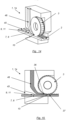
- figure 1 schematically shows that the width D3 of the first channel section 9 is, at least along a portion of its length and at least along a portion of its height, less than a distance D4 between the two opposite side walls 5, 6 of the rotating die 3.
- the first channel section 9 should be at least smaller in width than a distance between the opposing first and second channel portion side walls 15, 16 in the second channel section 10.
- the difference in width between the first channel section 9 and the second channel section 10 depends on features of the first and second side portions 23, 25 and tolerance between the rotating die 3 and the respective opposing first and second channel portion side walls 15, 16.
- the width D3 of the first channel section 9 should be less than a distance D4 being the distance between the opposing first and second channel portion side walls 15, 16 minus the sum of tolerances, i.e. the sum of the gap between the rotating die side walls 5, 6 and the respective opposing first and second channel portion side walls 15, 16 in the second channel section 10. If the first and second side portion comprises flange portions 18, 19, see below for further explanation, then the width D3 of the first channel section 9 is, at least along a portion of its length and at least along a portion of its height, less than a distance D4 between the two flange portions 18, 19.
- One advantage is that a local pressure reduction is achieved in connection to the first and second outer edge portions 5, 6 due to the geometrical difference in the first and second channel sections 9, 10.
- the local pressure reduction reduces the flow speed of the material and this removes leakage problems between the first side wall 5 and the first and the first channel portion side wall 15; and between the second side wall 6 and the second channel portion side wall 16. This will be explained further below and also in combination with additional leakage protection strategies.
- Figure 1 shows one example of an additional and figure 5 shows another example of leakage protection strategies. The different examples can be combined, which will be explained further below.
- rotating die 3 can be cylindrical or non-cylindrical and textured or not textured dependent on desired profile of the profile product.
- the rotating die 3 may be configured, before forming the profile product 2, to alter form during forming of the final profile 37 dependent on the maximum allowable pressure.
- at least a mid-portion 22 of the circumferential surface 4 of the rotating die 3 is convex in order to allow bending due to, at least, the forces and temperature during steady state production so that a predicted pattern 39 can be achieved in the final profile 37 during the steady state operation.
- steady state operation refers to stable operating conditions after a start-up procedure.
- the counter-bearing 14 is configured, before forming the profile product 2, to alter form during forming of the profile product 2 dependent on the maximum allowable pressure.
- the top pre-bearing 41 and/or the bottom pre-bearing 42 can be configured in a similar manner to change form a start-up procedure to a steady state operation.
- the rotating die 3 is configured with a pattern 38 with at least one indentation 38 with a bottom 44, wherein each indentation 38 comprises a release angle a2 compared to a release angle a1 of the corresponding elevation in the pattern 39 in the final profile 37.
- the release angles a1 and a2 are dependent on the radius of the rotating die 3, the intended pattern 39 in the final profile 37, the configuration of the counter bearing and travelling speed of the final profile 37.
- a1 is greater than a2 dependent on radius of the rotating die 3 and type of pattern 38 in the rotating die 3.
- Figures 4, 4A and 4B show that the indentation 38 in the pattern 38 has a height D23, alternatively called depth, in the radial direction R from the bottom 44 of the indentation 38 to the indentation delimiting portion in the circumferential surface 4 of the rotating die 3.
- the height D23 plus the distance D2 in figure 2B is equal to the maximum distance D22 in figures 2C and 2D and is thus relevant for the minimum allowable pressure for achieving plastic deformation of the material in the indentation 38.
- Figure 4A further shows that the pattern 39 in the final profile has an elevation with a height H4 that correspond to the depth D23 between the bottom 40 of the indentation 38 and the circumferential outer most portion of the rotating die 3.
- the first side portion 23 comprises a first flange portion 18 extending in a radial direction R with an extension exceeding the radial extension of at least a part of the mid-portion 22 and wherein the second side portion 25 comprises a second flange portion 19 extending in the radial direction with an extension exceeding the radial extension of at least a part of the mid-portion 22.
- the first flange portion 18 and the second flange portion 19 are arranged to prevent movement of the material outside the rotating die 3 in a direction towards the opposing first and second channel portion side walls 15, 16.
- the rotating die 3 can be arranged without flange portions which is shown at least in figures 2B-2D , 4, 4A and 4B .
- Fig. 5 schematically shows a cross-sectional side view of a device according to one example embodiment of the invention and fig. 6 schematically shows a back view and outlet of the device in figure 5 .
- the one or more walls 11 define a first cross-section 12 at the end of the first channel section 9 and wherein the second channel section 10 defines a second cross-section 17 at a position where the distance between the circumferential surface 4 and the counter-bearing 14 is at a minimum, and wherein the geometry of the first channel section 9 is different from the second channel section 10 such that the material passing through the first channel section 9 changes form when entering the second channel section 10.
- Fig. 7 schematically shows a cross-section of the master profile 36 taken in the first cross-section 12 of figure 5 and a cross-section of the final profile 37 taken in the second cross-section 17 of figure 5 according to one example;
- fig. 7 schematically shows a cross-section of the master profile 36 and the final profile 37 when using a non-textured rotating die, i.e. no pattern 38 with indentations 38 as described above.
- Fig. 8 schematically shows a cross-section of the master profile 36 taken in the first cross-section 12 of figure 5 and a first cross-section of the final profile 37 taken in the second cross-section 17 of figure 5 when the rotating die 3 has imprinted a pattern 39 in the final profile and a second cross-section of the final profile 37 taken in the second cross-section 17 of figure 5 when the rotating die 3 has not imprinted a pattern 39 in the final profile;
- fig. 8 schematically shows a cross-section of the master profile 36 and the final profile 37 when using a textured rotating die, i.e. with a pattern 38 with indentations 38 as described above.
- the pattern 38 in the rotating die causes a corresponding opposite pattern 39 in the final profile, i.e. when the pattern 38 in the rotating die 3 comprises an indentation 38, it causes a corresponding opposite pattern 39 comprising an elevation 39 in the final profile 37.
- the cross-section of the final profile 37 has been denoted 37a when the final profile has an elevation 39 caused by the indentation 38.
- the cross-section of the final profile 37 has been denoted 37b when the final profile lacks an elevation 39 caused by the circumferential surface 4 of the rotating die 3 in the space between the indentations 38.
- the master profile 36 has a first cross-section area geometry A1 corresponding to the first cross-section 12 and wherein the final profile 37 has a second cross-section area geometry A2 defined by the second cross-section 17, wherein the first cross-section area geometry A1 is different from the second cross-section area geometry A2 in any given comparable position, wherein the maximum pressure and thus the minimum distance D2 in the second channel section 10 is dependent on a difference of cross-section area geometry A1 of the master profile 36 and the cross-section area geometry A2 of the final profile 37.
- Figure 5 shows that the walls 11 are static and define a first cross-section 12 at the end of the first channel section 9 and wherein the second channel section 10 defines a second cross-section 17 at a position where the distance D2 between the circumferential surface 4 and the counter-bearing 14 is at a minimum, and wherein the geometry of the first channel section 9 is different from the second channel section 10 such that the material passing through the first channel section 9 changes form when entering the second channel section 10.
- the minimum distance D2 in the height direction Z between the circumferential surface 4 and the counter-bearing 14 in the second cross-section 17 is less than a maximum distance D1 in the height direction in the first cross-section 12. This has the advantage of forcing the material to change form and start flowing in various directions dependent on the shape and form of the rotating die 3 and shape and form of the counter-bearing 14 opposite the rotating die 3.
- the pressure in the second channel section 10 is increased or maintained to such level that the material will transform fast enough to saturate the second channel section, including an imprint of the rotating die.
- first channel section 9 and the second channel section 10 can be formed with different cross-section geometries such as oval, round, polygon, undulating or a combination of one or many shapes.
- the second channel section 10 is advantageously arranged in relation to the first channel section 9 with a predetermined second distance D2, shown in figure 5 , between the radially outermost portion of the circumferential surface 4 of the rotating die 3 and the counter-bearing 14 in the channel portion 13 being less than a predetermined first distance D1, shown in figure 5 , between the most far apart portions of the first channel section 9 taken in a height direction Z coinciding with the radial direction, and/or wherein: the second channel section 10 is arranged in relation to the first channel section 9 with a predetermined fourth distance D4, shown in figure 1 , between the innermost narrowest portions of the channel portion 13 in the width direction X being greater than a predetermined third distance D3, shown in figure 1 , between side walls in the first channel section taken in the width direction X at the exit area from the first channel.
- first and second side walls 5, 6 are positioned in relation to the first and second channel portion side walls 15, 16 such that the first and second side walls 5, 6 are rotatably connected to the first and second channel portion side walls 15, 16 with a tolerance arranged dependent on product material and the geometrical relation between the first and second channel sections 9, 10
- the circumferential surface 4 may comprise a textured portion 30 that can cover all the rotating die but the annular recess portion, or the first side portion 4 comprises a non-textured portion 31 extending between the first flange portion 18 and the textured portion 30 and wherein the second side portion 25 comprises a non-textured portion 32 between the second flange portion 19 and the textured portion 30.
- the non-textured portions 31, 32 advantageously has a radius less than a radius to an imprint depth of the textured portion 30, especially in the annular recess 19 portion.
- the circumferential surface 4 can be non-textured but with a smooth surface or a micro-patterned surface.
- the non-textured rotating die can have a shape being cylindrical or undulating.
- Fig. 9 schematically shows a back view and outlet of an assembly of rotary dies 3 including three rotary dies, 3, 33, 34 and fig. 10 schematically shows a perspective view of an assembly according to figure 9 .
- the channel portion 13 comprises a second rotating die 33 arranged opposite the first rotating die 3 replacing the counter-bearing 14 in figures 1 , 5 and 6 .
- the second rotating 33 die can either replace the counter-bearing 14 in its entirety or can be a part of a static counter-bearing 14 (not shown).
- the second rotating 33 die can be arranged in a similar way as the above described first rotating die 3 to create same or different patterns on two sides of the profile product.
- the second rotating die 33 can comprise annular recesses and/or flange portions that can be arranged to cooperate with annular recesses 29 and/or flange portions 18, 19 of the first rotating die 3.
- the channel portion 13 (shown in figures 1 , 5 and 6 ) comprises a third rotating die 34 arranged at an angle to the first rotating die.
- This rotating die replaces the opposing first or second channel portion side wall 15, 16 entirely or partly.
- the third rotating die 34 can be arranged together with only the first rotating die or together with both the first and second rotating die. Hence, the above described arrangement with a first rotating die 3 and a second opposing rotating die 33 can be assembled without the third rotating die 34.
- FIG. 11 schematically shows a back view and outlet of an assembly of rotary dies including four rotary dies
- fig. 12 schematically shows a perspective view of an assembly according to figure 19
- Figures 11 and 12 show that the channel portion 13 (shown in figures 1 , 5 and 6 ) comprises a fourth rotating die 35 arranged opposite the third rotating die 34.
- the fourth rotating die 34 can as an alternative be arranged together with only the first rotating die 3 or together with both the first and second rotating die 3, 33.
- the third and/or the fourth rotating die(s) 34, 35 can be arranged in a similar way as the above described first rotating die 3 to create same or different patterns on two sides of the profile product.
- the third and/or fourth rotating dies 34, 35 can comprise annular recesses and/or flange portions that can be arranged to cooperate with annular recesses 29 and/or flange portions 18, 19 of the first rotating die 3.
- two or more rotating dies are synchronised. This has the advantage of feeding the material at the same speed.
- non-synchronous rotating dies in order to create friction and/or a special pattern and/or to compensate for material differences.
- the device can be arranged with a combination of textured and non-textured rotating dies 3; 33; 34; 35.
- Figs 13-19 schematically show a co-extrusion device 1a and/or an on-extrusion device 1a comprising an extrusion and/or pultrusion device 1 according to any one of the examples discussed above, wherein the device 1a comprises at least two inlet channels 45, 46, 47 that connects directly or indirectly to the second channel section 10, wherein each of the at least two inlet channels 45, 46, 47 is configured to feed one or more materials at a predetermined distance upstream from the second channel section 10 or to a marriage point for the at least two inlet channels 45, 46, 47 in connection to where the first channel section 9 transitions into the second channel section 10.
- co-extrusion refers to where at least two material streams are together processed and formed into the master profile and then into the final profile or where the at least two material streams are together processed and formed into the final profile.
- on-extrusion refers to where the at least two material streams are positioned in a layered fashion either by being together processed and formed into the master profile and then into the final profile or by bringing together the at least two material streams into the master profile at the marriage point and thereafter together processing and forming the joint at least two material streams into the final profile in the second channel section 10.
- Fig. 13 schematically shows a cross-section side view of a device 1, 1a according to the invention.
- Figure 13 shows that the profile definition zone 7 comprises a first inlet channel 45 in the form of the first channel section 9 and a second inlet channel 46 in the form of a third channel section 46 connected to the profile definition zone 7 upstream the second channel section 10 for feeding an additional material to the second channel section 10 for forming a layered profile product 2 with material from the first channel section 9.
- the third channel section 46 is an extrusion- or pultrusion channel similar to the first channel section 9 arranged to work the material.
- the third channel section 46 is a third channel section that 46 is configured as a conveyer unit for conveying a material to the profile definition zone 7.
- Fig. 14 schematically shows a perspective view of a device according to invention
- fig. 15 schematically shows a cross-section side view of a device according to the invention.
- Figures 13-15 show in different ways that the device 1, 1a comprises one rotating device 3 as described above and two material streams that are brought together via the first and third channel sections 9, 46.
- Figure 16 schematically shows a cross-section side view of a device according to the invention where the device comprises two opposing rotating dies 3, 33.
- the device 1a comprises a first inlet channel 45 in the form of the first channel section and a second inlet channel 46 in the form of a third channel section 46 connected to the profile definition zone 7 upstream the second channel section 10 for feeding an additional material to the second channel section 10 for forming a layered profile product 2 with material from the first channel section 9.
- Figure 16 further shows that the device comprises a third inlet channel 47 in the form of a fourth channel section 47 for feeding a third material to the profile definition zone 7.
- the fourth channel section 47 is an extrusion- or pultrusion channel similar to the first channel section 9 arranged to work the material.
- the fourth channel section 47 is a fourth channel section that is configured as a conveyer unit for conveying a material to the profile definition zone 7.
- Fig. 17 schematically shows a cross-section side view of a device 1 according to the invention comprising one rotating die 3 and a first, third and fourth channel sections 9, 45, 46 for feeding three different materials to the profile definition zone 7 according to what is discussed in connection to figure 16 .
- the first inlet channel 45 may be the first channel section 9 or an inlet channel 45 that transports material to the first channel section 9.
- Figure 17 shows an example where the first inlet channel 45 conveys a solid material 50, e.g. a wire or a the like, to the first channel section 9 and where the second and third inlet channels 46, 47 introduces one or more materials to be extruded or pultruded in the first channel section 9 and the second channel section 10.
- the one or more materials may be layered onto the solid material or may surround the solid material.
- Figure 18 schematically shows an example where the first inlet channel 45 conveys a continuous solid material in the form of a wire or the like, and a material to be extruded or pultruded in the first and second channel sections 9, 10.
- the first inlet channel 45 and the second inlet channel 46 are arranged such that the material from the second inlet channel 46 surrounds the solid material 50 and embeds the solid material 50.
- the second inlet channel 46 comprises a pressurized chamber 51 upstream the first channel section 9 for forming the material around the solid material 50.
- the pressurized chamber 51 comprises a back wall 52 delimiting the pressurized chamber.
- the second inlet channel 46 comprises a feeding channel 53 to the pressurized chamber 51 for feeding the material to the chamber 51.
- the back wall 52 comprises the first inlet channel 45 that conveys the solid material 50 and acts as a stop for the material in the chamber to leak through the first inlet channel 45.
- pressurized means that the material in the second inlet channel 46 is subject to pressure by the material being forced into the second inlet channel 46 and deformed in a similar way as described above with relation to the first channel section 9.
- the first and second channel sections 9, 10 deforms the material in a similar manner as described above.
- Plastic deformation may take place also in the pressurized chamber, but is not limited to such deformation.
- the material in the pressurized chamber may be formed to surround the solid material without being deformed. All materials made from a viscoelastic material and/or plastically deformable material with elastic property and/or viscoplastic material with elastic property can be deformed in this example.
- the different materials are brought together before the second channel section 10 and is then worked in the second channel section as described above.
- the invention is not limited to three inlet channels 45, 46, 47 or three channel sections 9, 46, 47, but further inlet channels and channel sections are possible in order to manufacture a profile product with same or different materials in different layers.
- the material that is fed into the device to form the profile product is either one homogenous material or a mixture of two or more materials that are blended and or layered.
- the materials can be blended in different ratios and may be blended into a homogeneous mix or a mix with gradients within the material.
- One material can be a solid and another material can be mouldable, e.g. stone bits and rubber.
- the material can also be a layered material comprising two or more layers of same or different materials.
- the material may comprise one or more strings of solid material that follow through the entire extrusion or pultrusion process, e.g. a wire or another reinforcement material being surrounded by the deformable material.
- solid material refers to a material that does not undergo any deformation in the profile definition zone.
- solid materials are; bendable wire, stiff rod-like element, mesh of metal and/or fabric and/or composite and/or other suitable materials, a combination of such solid materials, etc.
- the maximum allowable pressure applied by the rotating die 3 at the position of the minimum distance D2 is dependent on friction between the material and the counter bearing 14 in the second channel section 10.
- the device 1 is configured to feed a friction material 48 between the counter-bearing 14 and the final profile 37 and/or configured to feed a friction material 48 between the rotating die 3 and the final profile 37.
- the friction material 48 is conveyed by the first and/or the second and/or the third inlet channels 45, 46, 47 at least during start-up of the device in order to control friction in connection to the rotating die 3 and/or the counter bearing 14.
- the friction material 18 is conveyed by the first and/or the second and/or the third inlet channels 45, 46, 47during a part of or the entire manufacturing process in order to control friction in connection to the rotating die 3 and/or the counter bearing 14.
- the friction material 48 is fed directly to the rotating die 3 such that the friction material rotates with the rotating die from a position before the second channel section 10 to the second channels section.
- Figure 2A schematically shows that the device 1 comprises an external friction material 48 feeding device 49 feeding the friction material 48 to the rotating die 3.
- the friction material 18 feeding device 49 can be either of the first, second or third inlet channels 45, 46, 47 (not shown).
- the friction material 48 may be a solid material, a liquid or a gas, or a combination thereof.
- the maximum pressure and thus the minimum distance D2 in the second channel section 10 is dependent on the total feeding rate of material in the first channel section 9, type of material, and temperature of the material when entering the second channel section 10.
- Figure 19 schematically shows a flow chart of a method for producing a profile product by use of a device according to what has been described in connection to figures 1 -26, wherein the method comprises the step shown in Box 101
- the method further comprises the step in box 104,
- the distance between indentations in the pattern on the rotating die is less than a distance between indentations in the corresponding pattern in the production direction on the profile product, wherein the pulling and stretching device is configured to stretch the final profile and/or the profile product so that high precision in distance between features on profile can be achieved by adjustment stretching.
Landscapes
- Engineering & Computer Science (AREA)
- Mechanical Engineering (AREA)
- Manufacturing & Machinery (AREA)
- Physics & Mathematics (AREA)
- Thermal Sciences (AREA)
- Chemical & Material Sciences (AREA)
- Composite Materials (AREA)
- Extrusion Moulding Of Plastics Or The Like (AREA)
- Extrusion Of Metal (AREA)
- Metal Extraction Processes (AREA)
- Casting Or Compression Moulding Of Plastics Or The Like (AREA)
Claims (15)
- Eine Extrusions- oder Pultrusionsvorrichtung (1) zum Formen eines Profilprodukts (2) aus einem viskoelastischen Material und/oder einem plastisch verformbaren Material mit elastischer Eigenschaft und/oder einem viskoplastischen Material mit elastischer Eigenschaft in einer Produktionsrichtung (Y), wobei die Vorrichtung Folgendes aufweist:- eine rotierende Matrize bzw. Pressform (3), die sich in einer radialen (R) Richtung und einer Breitenrichtung (X) erstreckt, mit zwei gegenüberliegenden ersten und zweiten Seitenwänden (5, 6) und einer äußeren Umfangsfläche (4), die sich in der Breitenrichtung (X) dazwischen erstreckt, wobei die rotierende Matrize (3) einen ersten Seitenabschnitt (23) in Verbindung mit der ersten Seitenwand (5) und einen zweiten Seitenabschnitt (25) in Verbindung mit der zweiten Seitenwand (6) und einen Mittelabschnitt (22) aufweist, der sich zwischen dem ersten und dem zweiten Seitenabschnitt (23, 25) erstreckt, und- einen Profildefinitionsbereich (7) mit einer Längsrichtung (Y), die mit der Produktionsrichtung (Y) übereinstimmt, mit einer Höhenrichtung (Z) und einer Breitenrichtung (X), die senkrecht zur Höhenrichtung (Z) verläuft, der einen Durchgangskanal (8) aufweist, der einen ersten Kanalabschnitt (9) aufweist, auf den ein zweiter Kanalabschnitt (10) folgt, der dem ersten Kanalabschnitt (9) in Bezug auf die Produktionsrichtung nachgelagert ist, wobei die rotierende Matrize (3) um eine Achse drehbar ist, die sich quer zur Produktionsrichtung (Y) erstreckt, und die so angeordnet ist, dass die äußere Umfangsfläche (4), während die rotierende Matrize (3) rotiert, einen Druck auf eine Oberfläche des Materials ausübt, und zwar wenn es durch die Profildefinitionszone (7) zugeführt wird, wobei;- der erste Kanalabschnitt (9) in Umfangsrichtung durch eine oder mehrere Wände (11) begrenzt ist und wobei- der zweite Kanalabschnitt (10) in Umfangsrichtung begrenzt ist dadurch, dassdadurch gekennzeichnet, dass- die Umfangsfläche (4) der rotierenden Matrize (3) und- ein Kanalabschnitt (13) - ein Gegenlager (14) gegenüber der rotierenden Matrize (3) und- gegenüberliegende erste und zweite Kanalabschnitt-Seitenwände (15, 16) zwischen der rotierenden Matrize (3) und dem Gegenlager (14) aufweisen, wobei optional die ersten und zweiten Seitenabschnitte (23, 24) der rotierenden Matrize (3) erste und zweite Flanschabschnitte (18, 19) aufweisen, die sich in einer radialen Richtung (R) mit einer Erstreckung erstrecken, die die radiale Erstreckung von mindestens einem Teil des Mittelabschnitts (22) der rotierenden Matrize (3) übersteigt, wobei die ersten und zweiten Flanschabschnitte (18, 19) so angeordnet sind, dass sie eine Bewegung des Materials außerhalb der rotierenden Matrize (3) verhindern,wobei der erste Kanalabschnitt (9) so konfiguriert ist, dass er das Material zu einem Masterprofil (36) verformt, das eine maximale Höhe (H1) bei einer vorbestimmten Vorschubgeschwindigkeit in Abhängigkeit von Material und minimaler Querschnittsfläche mit einer ersten maximalen Höhe (D1) in dem ersten Kanalabschnitt (9) hat, wenn es den ersten Kanalabschnitt verlässt,wobei der erste Kanalabschnitt (9) ein Nachlaufelement (58) aufweist, das eine vorgegebene Höhe (D5) in Abhängigkeit von der elastischen Eigenschaft des Materials hat,wobei das Nachlaufelement (58) zumindest in der Höhenrichtung positioniert ist und wobei der zweite Kanalabschnitt (10) so konfiguriert ist, dass er das Material weiter zu einem Endprofil (37) mit einer minimalen Höhe (H2) verformt, indem die rotierende Matrize (3) so konfiguriert ist, dass sie zunehmenden Druck auf das Masterprofil (36) gegen das Gegenlager (14) ausübt, wenn das Masterprofil (36) den ersten Kanalabschnitt (9) verlässt,wobei die rotierende Matrize (3) in einem Mindestabstand (D2) zwischen der rotierenden Matrize (3) und dem Gegenlager (14) konfiguriert ist, der von einem maximal zulässigen Druck abhängt, der von der rotierenden Matrize (3) an der Position dieses Mindestabstands (D2) ausgeübt wird, wobei der maximal zulässige Druck der maximalen Höhendifferenz zwischen dem Masterprofil (36) und dem Endprofil (37) entspricht und abhängig ist von einem Muster (38) in der Umfangsfläche (4) der rotierenden Matrize (3) und abhängig ist von der elastischen Eigenschaft des Materials und somit von der Differenz zwischen der Höhe (H3) des Endprofils und des Profilprodukts (2) aufgrund der Elastizität des Materials.
- Eine Vorrichtung (1) nach Anspruch 1, wobei das Nachlaufelement (58) dort angeordnet ist, wo der erste Kanalabschnitt (9) in den zweiten Kanalabschnitt (10) übergeht, wobei das Nachlaufelement eine obere Kante (59) mit einem untersten Teil, und zwar in der Höhenrichtung (Z), aufweist, wobei die obere Kante (59) einen oberen Bereich, und zwar in der Höhenrichtung (Z), des Nachlaufelements (58) im ersten Kanalabschnitt (9) an der vorbestimmten Stelle begrenzt, von wo der erste Kanalabschnitt (9) in den zweiten Kanalabschnitt (10) übergeht.
- Eine Vorrichtung (1) nach Anspruch 1, wobei das Nachlaufelement (58) in einem vorbestimmten Abstand in Produktionsrichtung (PD) der Stelle vorgelagert angeordnet ist, von wo der erste Kanalabschnitt (9) in den zweiten Kanalabschnitt (10) übergeht, wobei der erste Kanalabschnitt eine Oberkante (59) mit einem untersten Teil aufweist, und zwar in der Höhenrichtung (Z), wobei die Oberkante (59) einen oberen Abschnitt, und zwar in der Höhenrichtung (Z), der Wand (11) in dem ersten Kanalabschnitt (9) begrenzt, wo der erste Kanalabschnitt (9) in den zweiten Kanalabschnitt (10) übergeht.
- Eine Vorrichtung (1) nach Anspruch 2 oder 3, wobei die Höhe (H1) des Masterprofils beim Verlassen des ersten Kanalabschnitts (9) aufgrund von Elastizität kleiner oder gleich einer maximalen Höhe (H11) des Masterprofils im zweiten Kanalabschnitt (10) vor Erreichen der rotierenden Matrize (3) ist.
- Eine Vorrichtung (1) nach einem der vorhergehenden Ansprüche, wobei der erste Kanalabschnitt (9) mindestens zwei Seitenwände (11) in der Form eines oberen Vorlagers (41) und eines gegenüberliegenden unteren Vorlagers (42) aufweist, wobei das obere Vorlager (41) in der Höhenrichtung (Z) über dem gegenüberliegenden unteren Vorlager (42) angeordnet ist, wobei das obere Vorlager (41) und/oder das untere Vorlager (42) das Nachlaufelement (58) aufweist, und/oder wobei die eine oder die mehreren Wände (11) einen ersten Querschnitt (12) am Ende des ersten Kanalabschnitts (9) definieren und wobei der zweite Kanalabschnitt (10) einen zweiten Querschnitt (17) an einer Position definiert, an der der Abstand zwischen der Umfangsfläche (4) und dem Gegenlager (14) minimal ist, und wobei sich die Geometrie des ersten Kanalabschnitts (9) von der des zweiten Kanalabschnitts (10) derart unterscheidet, dass das durch den ersten Kanalabschnitt (9) hindurchtretende Material beim Eintritt in den zweiten Kanalabschnitt (10) seine Form ändert,
wobei das Masterprofil (36) eine dem ersten Querschnitt (12) entsprechende erste Querschnittsflächengeometrie (A1) aufweist und wobei das Endprofil (37) eine durch den zweiten Querschnitt definierte zweite Querschnittsflächengeometrie (A2) aufweist, wobei sich die erste Querschnittsflächengeometrie (A1) in jeder vergleichbaren Position von der zweiten Querschnittsflächengeometrie (A2) unterscheidet, wobei der maximale Druck und damit der minimale Abstand (D2) im zweiten Kanalabschnitt (10) abhängig ist von einer Differenz der Querschnittsflächengeometrie (A1) des Masterprofils (36) und der Querschnittsflächengeometrie (A2) des Endprofils (37) und der elastischen Eigenschaft des Materials. - Eine Vorrichtung (1) nach einem der vorhergehenden Ansprüche, wobei die rotierende Matrize (3) ein Muster (38) aufweist, das mindestens eine Vertiefung (38) aufweist, wobei die rotierende Matrize (3) in einem maximalen Abstand (D22) zwischen einem Boden (44) der Vertiefung (38) und dem Gegenlager (14) konfiguriert ist, der von einem minimal zulässigen Druck abhängt, der von der rotierenden Matrize an der Position dieses maximalen Abstands (D22) ausgeübt wird, um plastische Verformung des Materials in der Vertiefung (38) zu erreichen, und/oder wobei der maximale Druck und somit der minimale Abstand (D2) in dem zweiten Kanalabschnitt (10) von der Gesamtzuführungsrate des Materials in dem ersten Kanalabschnitt (9), von der Art des Materials und von der Temperatur des Materials beim Eintritt in den zweiten Kanalabschnitt (10) abhängt.
- Eine Vorrichtung (1) nach einem der vorhergehenden Ansprüche, wobei der maximal zulässige Druck, der von der rotierenden Matrize (3) an der Position des Mindestabstands ausgeübt wird, von Reibung zwischen dem Material und dem Gegenlager (14) in dem zweiten Kanalabschnitt (10) abhängt, und/oder wobei die Querschnittsfläche (A1) des zweiten Kanalabschnitts (10) so konfiguriert ist, dass sie im Hinblick auf einen Schrumpfungseffekt des Endprofils (37), das zu dem Profilprodukt (2) mit einer Endhöhe (H3) abkühlt, und auf die elastische Eigenschaft des Materials bemessen ist.
- Eine Vorrichtung (1) nach einem der vorhergehenden Ansprüche, wobei das Muster (38) in der rotierenden Matrize (3) im Hinblick auf einen Schrumpfungseffekt des auf das Profilprodukt (2) abkühlenden Endprofils (37) und die elastische Eigenschaft des Materials bemessen ist, und/oder wobei die rotierende Matrize (3) mit einem Muster (38) mit mindestens einer Vertiefung (38) ausgebildet ist, wobei jede Vertiefung (38) einen vom Radius der rotierenden Matrize (3) abhängigen Auslösewinkel (a2) aufweist, vom vorgesehenen Muster im Endprofil, von der Konfiguration des Gegenlagers und von der Fahrgeschwindigkeit des Endprofils (37).
- Eine Vorrichtung (1) nach einem der vorhergehenden Ansprüche, wobei die Vorrichtung (1) so konfiguriert ist, dass sie ein Reibmaterial (48) zwischen dem Gegenlager (14) und dem Endprofil (37) zuführt und/oder so konfiguriert ist, dass sie ein Reibmaterial (48) zwischen der rotierenden Matrize (3) und dem Endprofil (37) zuführt, und/oder wobei die Vorrichtung (1) eine Zieh- und Streckvorrichtung (54) aufweist, die dem zweiten Kanalabschnitt (10) nachgelagert angeordnet und so konfiguriert ist, dass sie das aus dem zweiten Kanalabschnitt (10) austretende Material zieht, um das Endprofil (37) in das Profilprodukt (2) umzuwandeln.
- Eine Vorrichtung (1) nach einem der vorhergehenden Ansprüche, wobei die Vorrichtung eine Zieh- und Streckvorrichtung (54) aufweist, und wobei ein Abstand zwischen Vertiefungen (38) in dem Muster (38) auf der rotierenden Matrize (3) geringer ist als ein Abstand zwischen Erhebungen (40) in dem entsprechenden Muster (38) in der Produktionsrichtung (Y) auf dem Profilprodukt (2), wobei die Zieh- und Streckvorrichtung (54) so konfiguriert ist, dass sie das Endprofil (37) und/oder das Profilprodukt (2) streckt, so dass hohe Präzision im Abstand zwischen Merkmalen auf dem Profil durch Streckeinstellung erreicht werden kann.
- Eine Vorrichtung (1) nach einem der vorhergehenden Ansprüche, wobei die rotierende Matrize (3) eine Kühlvorrichtung aufweist, die so konfiguriert ist, dass sie die Außenfläche der rotierenden Matrize (3) abkühlt, so dass die Temperatur der Oberfläche der rotierenden Matrize (3) unter einer vorbestimmten zulässigen Temperatur des extrudierten Materials liegt, wobei die rotierende Matrize (3) an der Oberfläche optional so gekühlt wird, dass die Temperatur der Oberfläche der rotierenden Matrize mindestens 10 Grad Celsius unter einer Glasübergangstemperatur oder Schmelztemperatur des Materials liegt, wobei die rotierende Matrize (3) optional an der Oberfläche so gekühlt wird, dass die Temperatur der Oberfläche der rotierenden Matrize mindestens 50 Grad Celsius unter einer Glasübergangstemperatur oder Schmelztemperatur des Materials liegt, was eine höhere Extrusionsgeschwindigkeit ermöglicht.
- Eine Vorrichtung (1) nach einem der vorhergehenden Ansprüche, wobei das Material, das der Vorrichtung zugeführt wird, um das Profilprodukt (2) zu bilden, entweder ein homogenes Material oder eine Mischung aus zwei oder mehr Materialien ist, die gemischt und/oder geschichtet sind.
- Eine Co-Extrusionsvorrichtung (1a) und/oder eine On-Extrusionsvorrichtung (1a) mit einer Vorrichtung (1) nach einem der vorhergehenden Ansprüche, wobei die Vorrichtung (1) mindestens zwei Einlasskanäle (45, 46, 47) aufweist, die direkt oder indirekt mit dem zweiten Kanalabschnitt (10) verbunden sind, wobei jeder der mindestens zwei Einlasskanäle (45, 46, 47) so konfiguriert ist, dass er ein oder mehrere Materialien in einem vorbestimmten Abstand vorgelagert zum zweiten Kanalabschnitt (10) oder zu einem Verbindungspunkt für die mindestens zwei Einlasskanäle (45, 46, 47) in Verbindung mit der Stelle zuführt, an der der erste Kanalabschnitt (9) in den zweiten Kanalabschnitt (10) übergeht.
- Ein Verfahren zur Herstellung eines Profilprodukts (2) unter Verwendung einer Vorrichtung (1, 1a) nach einem der vorhergehenden Ansprüche, wobei das Verfahren Folgendes aufweist:- Zuführen eines Materials zu dem ersten Kanalabschnitt (9) und Formen desselben zu einem Masterprofil (36) in dem ersten Kanalabschnitt (9),- weiteres Zuführen des Materials zu dem zweiten Kanalabschnitt (10) und Formen desselben zu einem Endprofil (37) im zweiten Kanalabschnitt (10),- Umwandeln des Endprofils in das Profilprodukt (2).
- Ein Verfahren nach Anspruch 14, wobei das Endprofil (2) und/oder das Profilprodukt (2) gestreckt wird, um den gleichen Abstand im Muster entlang der Produktionsrichtung (Y) zu erreichen.
Applications Claiming Priority (2)
| Application Number | Priority Date | Filing Date | Title |
|---|---|---|---|
| SE2051217A SE2051217A1 (en) | 2020-10-20 | 2020-10-20 | An extrusion and/or pultrusion device and method for forming material with elastic properties |
| PCT/EP2021/078186 WO2022084107A1 (en) | 2020-10-20 | 2021-10-12 | An extrusion and/or pultrusion device and method |
Publications (3)
| Publication Number | Publication Date |
|---|---|
| EP4232256A1 EP4232256A1 (de) | 2023-08-30 |
| EP4232256C0 EP4232256C0 (de) | 2024-08-07 |
| EP4232256B1 true EP4232256B1 (de) | 2024-08-07 |
Family
ID=77920331
Family Applications (1)
| Application Number | Title | Priority Date | Filing Date |
|---|---|---|---|
| EP21794121.0A Active EP4232256B1 (de) | 2020-10-20 | 2021-10-12 | Extrusions- und/oder pultrusionsvorrichtung und -verfahren |
Country Status (7)
| Country | Link |
|---|---|
| US (1) | US12384092B2 (de) |
| EP (1) | EP4232256B1 (de) |
| JP (1) | JP2023550258A (de) |
| KR (1) | KR20230090350A (de) |
| CN (1) | CN116390843A (de) |
| SE (1) | SE2051217A1 (de) |
| WO (1) | WO2022084107A1 (de) |
Families Citing this family (4)
| Publication number | Priority date | Publication date | Assignee | Title |
|---|---|---|---|---|
| SE2051217A1 (en) * | 2020-10-20 | 2021-10-12 | Reliefed Ab | An extrusion and/or pultrusion device and method for forming material with elastic properties |
| SE544100C2 (en) * | 2020-10-20 | 2021-12-21 | Reliefed Ab | An extrusion and/or pultrusion device and method for forming plastically deformable and/or viscoplastic material |
| SE545779C2 (en) * | 2021-08-31 | 2024-01-09 | Reliefed Ab | Energy storage device comprising an electrode product manufactured by an extrusion device and vehicle comprising the energy storage device |
| CN115488177B (zh) * | 2022-10-31 | 2023-08-25 | 江西江冶实业有限公司 | 一种用于铜排挤压成型设备及其成型工艺 |
Citations (1)
| Publication number | Priority date | Publication date | Assignee | Title |
|---|---|---|---|---|
| US20180193891A1 (en) * | 2015-07-04 | 2018-07-12 | Reliefed Ab | Extrusion of profiles utilising opposite rotating dies |
Family Cites Families (41)
| Publication number | Priority date | Publication date | Assignee | Title |
|---|---|---|---|---|
| US2892212A (en) * | 1955-04-05 | 1959-06-30 | Us Rubber Co | Extrusion apparatus |
| US3394431A (en) * | 1964-09-15 | 1968-07-30 | George S. Nalle Jr. | Apparatus for extruding plastic mesh, lace or net fabrics |
| US3635631A (en) * | 1970-06-10 | 1972-01-18 | Du Pont | Continuous molding of thermoplastic resin |
| US3782872A (en) * | 1972-03-15 | 1974-01-01 | G Nalle | Apparatus for extruding woven plastic mesh |
| US3869304A (en) * | 1972-11-20 | 1975-03-04 | Uniroyal Inc | Fabric coating by extrusion die-calendering apparatus and method |
| US4631161A (en) * | 1983-01-18 | 1986-12-23 | Anatoliy Popow | Continuous molding method |
| US4497619A (en) * | 1983-01-18 | 1985-02-05 | Anatoliy Popow | Continuous molding apparatus |
| US4950151A (en) * | 1985-01-31 | 1990-08-21 | Zachariades Anagnostic E | Rolling die for producing high modulus products |
| US4820466A (en) * | 1985-01-31 | 1989-04-11 | Zachariades Anagnostis E | Process for obtaining ultra-high modulus products |
| DE3806387A1 (de) * | 1988-02-29 | 1989-09-07 | Troester Maschf Paul | Verfahren und vorrichtung zur bearbeitung von elastomerischen massen, insbesondere kunststoff, kautschuk und deren mischungen |
| US5030079A (en) * | 1989-10-27 | 1991-07-09 | The Goodyear Tire & Rubber Company | Roller die extrusion and calendering apparatus |
| US5186960A (en) * | 1990-11-07 | 1993-02-16 | Walsh Jr Thomas J | Low pressure 3D extrusion |
| DE4035476C2 (de) * | 1990-11-08 | 1996-10-17 | Troester Maschf Paul | Extruder-Kalander-Kombination |
| FR2700291A1 (fr) * | 1993-01-08 | 1994-07-13 | Michelin & Cie | Appareil d'extrusion et procédé d'extrusion pour mélanges de caoutchouc cru. |
| JPH0716643A (ja) * | 1993-07-05 | 1995-01-20 | Toyo Kanetsu Kk | アルミニウム材の成形方法及び成形装置 |
| SE9503474L (sv) * | 1995-10-06 | 1996-12-23 | Mark Lars Jansson | Förfarande för kontinuerlig framställning av profiler och anordning för genomförande av förfarandet |
| US5904884A (en) * | 1997-06-26 | 1999-05-18 | Decoma International Inc. | Method of forming automotive trim strip from extruded thermoplastic materials |
| ATE268352T1 (de) * | 1997-12-05 | 2004-06-15 | Roehm Gmbh | VERFAHREN ZUR HERSTELLUNG VON OBERFLÄCHENHARTEN, IM ßFILM-INSERT-MOULDINGß-VERFAHREN HANDHABBAREN, BEIDSEITIG HOCHGLÄNZENDEN, GELKÖRPERFREIEN PMMA- FOLIEN |
| DE10126124A1 (de) * | 2000-06-01 | 2001-12-06 | Sumitomo Chemical Co | Strangpreßmaschine |
| BR0115641A (pt) * | 2000-11-27 | 2003-09-02 | Michelin Soc Tech | Dispositivo de extrusão para fabricar um produto à base de uma mistura borrachosa, e, aparelhagem de extrusão de várias misturas borrachosas |
| AU2002313247A1 (en) * | 2002-06-17 | 2003-12-31 | Mikio Fukumura | Foam forming die, and method of manufacturing foam formed product using the die |
| US7186110B2 (en) * | 2004-09-17 | 2007-03-06 | Francis Chung Hwa Pan | Apparatus of making wedged plates |
| WO2009037736A1 (ja) * | 2007-09-18 | 2009-03-26 | Toyo Tire & Rubber Co., Ltd. | ゴムストリップ材の成形装置及びゴムストリップ材の成形方法 |
| JP5339350B2 (ja) * | 2009-01-23 | 2013-11-13 | サンアロマー株式会社 | 結晶性樹脂フィルムまたはシートの製造方法および製造装置 |
| FR2968592B1 (fr) * | 2010-12-13 | 2013-01-11 | Michelin Soc Tech | Procede de fabrication d'une ebauche de pneumatique au moyen d'une nappe comprenant deux gommes |
| US8414284B2 (en) * | 2011-01-04 | 2013-04-09 | The Goodyear Tire & Rubber Company | Extruder and roller-die combination |
| CN104010515B (zh) * | 2011-02-24 | 2017-05-10 | 呼瓦基有限责任公司 | 用于挤出具有微结构的部件的系统和方法 |
| US20130126543A1 (en) * | 2011-11-22 | 2013-05-23 | Timothy H. Bohrer | Sheet with multiple thickness and methods for forming same |
| TW201347954A (zh) * | 2012-05-23 | 2013-12-01 | Hon Hai Prec Ind Co Ltd | 光學膜片製造裝置及光學膜片製造方法 |
| FR3001654B1 (fr) * | 2013-02-01 | 2015-06-19 | Michelin & Cie | Appareil et procede pour extruder un melange d'elastomere |
| US9649792B2 (en) * | 2013-10-15 | 2017-05-16 | Velcro BVBA | Forming longitudinally pleated products |
| US9962851B2 (en) * | 2013-12-12 | 2018-05-08 | 3M Innovative Properties Company | Method of making polymeric multilayer films |
| JP6814709B2 (ja) * | 2017-08-10 | 2021-01-20 | 株式会社神戸製鋼所 | ロール付スクリュ押出機 |
| SE543402C2 (en) * | 2019-05-06 | 2021-01-05 | Reliefed Ab | An extrusion and/or pultrusion device and method |
| SE543926C2 (en) * | 2019-05-06 | 2021-09-28 | Reliefed Ab | An extrusion and/or pultrusion device and method |
| SE543730C2 (en) * | 2019-05-06 | 2021-07-06 | Reliefed Ab | An extrusion and/or pultrusion device and method |
| SE543400C2 (en) * | 2019-05-06 | 2021-01-05 | Reliefed Ab | An extrusion and / or pultrusion device and method |
| SE543401C2 (en) * | 2019-05-06 | 2021-01-05 | Reliefed Ab | An extrusion and/or pultrusion device and method |
| SE544100C2 (en) * | 2020-10-20 | 2021-12-21 | Reliefed Ab | An extrusion and/or pultrusion device and method for forming plastically deformable and/or viscoplastic material |
| SE2051218A1 (en) * | 2020-10-20 | 2021-11-02 | Reliefed Ab | An extrusion and/or pultrusion device and method |
| SE2051217A1 (en) * | 2020-10-20 | 2021-10-12 | Reliefed Ab | An extrusion and/or pultrusion device and method for forming material with elastic properties |
-
2020
- 2020-10-20 SE SE2051217A patent/SE2051217A1/en unknown
-
2021
- 2021-10-12 JP JP2023524404A patent/JP2023550258A/ja active Pending
- 2021-10-12 WO PCT/EP2021/078186 patent/WO2022084107A1/en not_active Ceased
- 2021-10-12 CN CN202180071745.5A patent/CN116390843A/zh active Pending
- 2021-10-12 EP EP21794121.0A patent/EP4232256B1/de active Active
- 2021-10-12 KR KR1020237017002A patent/KR20230090350A/ko not_active Withdrawn
- 2021-10-12 US US18/032,364 patent/US12384092B2/en active Active
Patent Citations (1)
| Publication number | Priority date | Publication date | Assignee | Title |
|---|---|---|---|---|
| US20180193891A1 (en) * | 2015-07-04 | 2018-07-12 | Reliefed Ab | Extrusion of profiles utilising opposite rotating dies |
Also Published As
| Publication number | Publication date |
|---|---|
| US12384092B2 (en) | 2025-08-12 |
| SE543969C2 (en) | 2021-10-12 |
| KR20230090350A (ko) | 2023-06-21 |
| EP4232256A1 (de) | 2023-08-30 |
| SE2051217A1 (en) | 2021-10-12 |
| JP2023550258A (ja) | 2023-12-01 |
| CN116390843A (zh) | 2023-07-04 |
| WO2022084107A1 (en) | 2022-04-28 |
| EP4232256C0 (de) | 2024-08-07 |
| US20230382036A1 (en) | 2023-11-30 |
Similar Documents
| Publication | Publication Date | Title |
|---|---|---|
| EP4232256B1 (de) | Extrusions- und/oder pultrusionsvorrichtung und -verfahren | |
| EP4232255B1 (de) | Extrusions- und/oder pultrusionsvorrichtung und -verfahren | |
| EP4232216B1 (de) | Extrusions- und/oder pultrusionsvorrichtung und -verfahren | |
| US10875069B2 (en) | Extrusion of profiles utilising opposite rotating dies | |
| EP3965970B1 (de) | Extrusions- und/oder pultrusionsvorrichtung und -verfahren | |
| US12384091B2 (en) | Extrusion and/or pultrusion device and method | |
| CN100475487C (zh) | 粘弹性材料的挤型模 | |
| EP3965971A1 (de) | Extrusions- und/oder pultrusionsvorrichtung und -verfahren | |
| SE545779C2 (en) | Energy storage device comprising an electrode product manufactured by an extrusion device and vehicle comprising the energy storage device | |
| US20250091247A1 (en) | A production method, and a ceramic product obtained by such method | |
| CA3138470C (en) | An extrusion and/or pultrusion device and method |
Legal Events
| Date | Code | Title | Description |
|---|---|---|---|
| STAA | Information on the status of an ep patent application or granted ep patent |
Free format text: STATUS: UNKNOWN |
|
| STAA | Information on the status of an ep patent application or granted ep patent |
Free format text: STATUS: THE INTERNATIONAL PUBLICATION HAS BEEN MADE |
|
| PUAI | Public reference made under article 153(3) epc to a published international application that has entered the european phase |
Free format text: ORIGINAL CODE: 0009012 |
|
| STAA | Information on the status of an ep patent application or granted ep patent |
Free format text: STATUS: REQUEST FOR EXAMINATION WAS MADE |
|
| 17P | Request for examination filed |
Effective date: 20230517 |
|
| AK | Designated contracting states |
Kind code of ref document: A1 Designated state(s): AL AT BE BG CH CY CZ DE DK EE ES FI FR GB GR HR HU IE IS IT LI LT LU LV MC MK MT NL NO PL PT RO RS SE SI SK SM TR |
|
| DAV | Request for validation of the european patent (deleted) | ||
| DAX | Request for extension of the european patent (deleted) | ||
| GRAP | Despatch of communication of intention to grant a patent |
Free format text: ORIGINAL CODE: EPIDOSNIGR1 |
|
| STAA | Information on the status of an ep patent application or granted ep patent |
Free format text: STATUS: GRANT OF PATENT IS INTENDED |
|
| INTG | Intention to grant announced |
Effective date: 20240229 |
|
| GRAS | Grant fee paid |
Free format text: ORIGINAL CODE: EPIDOSNIGR3 |
|
| GRAA | (expected) grant |
Free format text: ORIGINAL CODE: 0009210 |
|
| STAA | Information on the status of an ep patent application or granted ep patent |
Free format text: STATUS: THE PATENT HAS BEEN GRANTED |
|
| AK | Designated contracting states |
Kind code of ref document: B1 Designated state(s): AL AT BE BG CH CY CZ DE DK EE ES FI FR GB GR HR HU IE IS IT LI LT LU LV MC MK MT NL NO PL PT RO RS SE SI SK SM TR |
|
| REG | Reference to a national code |
Ref country code: GB Ref legal event code: FG4D |
|
| REG | Reference to a national code |
Ref country code: CH Ref legal event code: EP |
|
| REG | Reference to a national code |
Ref country code: DE Ref legal event code: R096 Ref document number: 602021016974 Country of ref document: DE |
|
| REG | Reference to a national code |
Ref country code: IE Ref legal event code: FG4D |
|
| U01 | Request for unitary effect filed |
Effective date: 20240906 |
|
| U07 | Unitary effect registered |
Designated state(s): AT BE BG DE DK EE FI FR IT LT LU LV MT NL PT RO SE SI Effective date: 20240920 |
|
| PG25 | Lapsed in a contracting state [announced via postgrant information from national office to epo] |
Ref country code: NO Free format text: LAPSE BECAUSE OF FAILURE TO SUBMIT A TRANSLATION OF THE DESCRIPTION OR TO PAY THE FEE WITHIN THE PRESCRIBED TIME-LIMIT Effective date: 20241107 |
|
| U20 | Renewal fee for the european patent with unitary effect paid |
Year of fee payment: 4 Effective date: 20241211 |
|
| PG25 | Lapsed in a contracting state [announced via postgrant information from national office to epo] |
Ref country code: GR Free format text: LAPSE BECAUSE OF FAILURE TO SUBMIT A TRANSLATION OF THE DESCRIPTION OR TO PAY THE FEE WITHIN THE PRESCRIBED TIME-LIMIT Effective date: 20241108 Ref country code: PL Free format text: LAPSE BECAUSE OF FAILURE TO SUBMIT A TRANSLATION OF THE DESCRIPTION OR TO PAY THE FEE WITHIN THE PRESCRIBED TIME-LIMIT Effective date: 20240807 |
|
| PG25 | Lapsed in a contracting state [announced via postgrant information from national office to epo] |
Ref country code: IS Free format text: LAPSE BECAUSE OF FAILURE TO SUBMIT A TRANSLATION OF THE DESCRIPTION OR TO PAY THE FEE WITHIN THE PRESCRIBED TIME-LIMIT Effective date: 20241207 |
|
| PG25 | Lapsed in a contracting state [announced via postgrant information from national office to epo] |
Ref country code: HR Free format text: LAPSE BECAUSE OF FAILURE TO SUBMIT A TRANSLATION OF THE DESCRIPTION OR TO PAY THE FEE WITHIN THE PRESCRIBED TIME-LIMIT Effective date: 20240807 |
|
| PG25 | Lapsed in a contracting state [announced via postgrant information from national office to epo] |
Ref country code: ES Free format text: LAPSE BECAUSE OF FAILURE TO SUBMIT A TRANSLATION OF THE DESCRIPTION OR TO PAY THE FEE WITHIN THE PRESCRIBED TIME-LIMIT Effective date: 20240807 Ref country code: RS Free format text: LAPSE BECAUSE OF FAILURE TO SUBMIT A TRANSLATION OF THE DESCRIPTION OR TO PAY THE FEE WITHIN THE PRESCRIBED TIME-LIMIT Effective date: 20241107 |
|
| PG25 | Lapsed in a contracting state [announced via postgrant information from national office to epo] |
Ref country code: RS Free format text: LAPSE BECAUSE OF FAILURE TO SUBMIT A TRANSLATION OF THE DESCRIPTION OR TO PAY THE FEE WITHIN THE PRESCRIBED TIME-LIMIT Effective date: 20241107 Ref country code: PL Free format text: LAPSE BECAUSE OF FAILURE TO SUBMIT A TRANSLATION OF THE DESCRIPTION OR TO PAY THE FEE WITHIN THE PRESCRIBED TIME-LIMIT Effective date: 20240807 Ref country code: NO Free format text: LAPSE BECAUSE OF FAILURE TO SUBMIT A TRANSLATION OF THE DESCRIPTION OR TO PAY THE FEE WITHIN THE PRESCRIBED TIME-LIMIT Effective date: 20241107 Ref country code: IS Free format text: LAPSE BECAUSE OF FAILURE TO SUBMIT A TRANSLATION OF THE DESCRIPTION OR TO PAY THE FEE WITHIN THE PRESCRIBED TIME-LIMIT Effective date: 20241207 Ref country code: HR Free format text: LAPSE BECAUSE OF FAILURE TO SUBMIT A TRANSLATION OF THE DESCRIPTION OR TO PAY THE FEE WITHIN THE PRESCRIBED TIME-LIMIT Effective date: 20240807 Ref country code: GR Free format text: LAPSE BECAUSE OF FAILURE TO SUBMIT A TRANSLATION OF THE DESCRIPTION OR TO PAY THE FEE WITHIN THE PRESCRIBED TIME-LIMIT Effective date: 20241108 Ref country code: ES Free format text: LAPSE BECAUSE OF FAILURE TO SUBMIT A TRANSLATION OF THE DESCRIPTION OR TO PAY THE FEE WITHIN THE PRESCRIBED TIME-LIMIT Effective date: 20240807 |
|
| PG25 | Lapsed in a contracting state [announced via postgrant information from national office to epo] |
Ref country code: SM Free format text: LAPSE BECAUSE OF FAILURE TO SUBMIT A TRANSLATION OF THE DESCRIPTION OR TO PAY THE FEE WITHIN THE PRESCRIBED TIME-LIMIT Effective date: 20240807 |
|
| PG25 | Lapsed in a contracting state [announced via postgrant information from national office to epo] |
Ref country code: CZ Free format text: LAPSE BECAUSE OF FAILURE TO SUBMIT A TRANSLATION OF THE DESCRIPTION OR TO PAY THE FEE WITHIN THE PRESCRIBED TIME-LIMIT Effective date: 20240807 |
|
| PG25 | Lapsed in a contracting state [announced via postgrant information from national office to epo] |
Ref country code: SK Free format text: LAPSE BECAUSE OF FAILURE TO SUBMIT A TRANSLATION OF THE DESCRIPTION OR TO PAY THE FEE WITHIN THE PRESCRIBED TIME-LIMIT Effective date: 20240807 |
|
| REG | Reference to a national code |
Ref country code: CH Ref legal event code: PL |
|
| PLBE | No opposition filed within time limit |
Free format text: ORIGINAL CODE: 0009261 |
|
| STAA | Information on the status of an ep patent application or granted ep patent |
Free format text: STATUS: NO OPPOSITION FILED WITHIN TIME LIMIT |
|
| PG25 | Lapsed in a contracting state [announced via postgrant information from national office to epo] |
Ref country code: MC Free format text: LAPSE BECAUSE OF FAILURE TO SUBMIT A TRANSLATION OF THE DESCRIPTION OR TO PAY THE FEE WITHIN THE PRESCRIBED TIME-LIMIT Effective date: 20240807 |
|
| 26N | No opposition filed |
Effective date: 20250508 |
|
| PG25 | Lapsed in a contracting state [announced via postgrant information from national office to epo] |
Ref country code: CH Free format text: LAPSE BECAUSE OF NON-PAYMENT OF DUE FEES Effective date: 20241031 |
|
| PG25 | Lapsed in a contracting state [announced via postgrant information from national office to epo] |
Ref country code: IE Free format text: LAPSE BECAUSE OF NON-PAYMENT OF DUE FEES Effective date: 20241012 |
|
| U20 | Renewal fee for the european patent with unitary effect paid |
Year of fee payment: 5 Effective date: 20251016 |
|
| PG25 | Lapsed in a contracting state [announced via postgrant information from national office to epo] |
Ref country code: CY Free format text: LAPSE BECAUSE OF FAILURE TO SUBMIT A TRANSLATION OF THE DESCRIPTION OR TO PAY THE FEE WITHIN THE PRESCRIBED TIME-LIMIT; INVALID AB INITIO Effective date: 20211012 |
|
| PG25 | Lapsed in a contracting state [announced via postgrant information from national office to epo] |
Ref country code: HU Free format text: LAPSE BECAUSE OF FAILURE TO SUBMIT A TRANSLATION OF THE DESCRIPTION OR TO PAY THE FEE WITHIN THE PRESCRIBED TIME-LIMIT; INVALID AB INITIO Effective date: 20211012 |