EP4230424A1 - Transport device and droplet ejecting device - Google Patents
Transport device and droplet ejecting device Download PDFInfo
- Publication number
- EP4230424A1 EP4230424A1 EP23157723.0A EP23157723A EP4230424A1 EP 4230424 A1 EP4230424 A1 EP 4230424A1 EP 23157723 A EP23157723 A EP 23157723A EP 4230424 A1 EP4230424 A1 EP 4230424A1
- Authority
- EP
- European Patent Office
- Prior art keywords
- sponge
- transport
- unit
- support
- compressed
- Prior art date
- Legal status (The legal status is an assumption and is not a legal conclusion. Google has not performed a legal analysis and makes no representation as to the accuracy of the status listed.)
- Granted
Links
Images




Classifications
-
- B—PERFORMING OPERATIONS; TRANSPORTING
- B41—PRINTING; LINING MACHINES; TYPEWRITERS; STAMPS
- B41J—TYPEWRITERS; SELECTIVE PRINTING MECHANISMS, i.e. MECHANISMS PRINTING OTHERWISE THAN FROM A FORME; CORRECTION OF TYPOGRAPHICAL ERRORS
- B41J29/00—Details of, or accessories for, typewriters or selective printing mechanisms not otherwise provided for
- B41J29/17—Cleaning arrangements
-
- B—PERFORMING OPERATIONS; TRANSPORTING
- B41—PRINTING; LINING MACHINES; TYPEWRITERS; STAMPS
- B41J—TYPEWRITERS; SELECTIVE PRINTING MECHANISMS, i.e. MECHANISMS PRINTING OTHERWISE THAN FROM A FORME; CORRECTION OF TYPOGRAPHICAL ERRORS
- B41J11/00—Devices or arrangements of selective printing mechanisms, e.g. ink-jet printers or thermal printers, for supporting or handling copy material in sheet or web form
- B41J11/007—Conveyor belts or like feeding devices
-
- B—PERFORMING OPERATIONS; TRANSPORTING
- B65—CONVEYING; PACKING; STORING; HANDLING THIN OR FILAMENTARY MATERIAL
- B65G—TRANSPORT OR STORAGE DEVICES, e.g. CONVEYORS FOR LOADING OR TIPPING, SHOP CONVEYOR SYSTEMS OR PNEUMATIC TUBE CONVEYORS
- B65G45/00—Lubricating, cleaning, or clearing devices
- B65G45/10—Cleaning devices
- B65G45/18—Cleaning devices comprising brushes
-
- B—PERFORMING OPERATIONS; TRANSPORTING
- B08—CLEANING
- B08B—CLEANING IN GENERAL; PREVENTION OF FOULING IN GENERAL
- B08B1/00—Cleaning by methods involving the use of tools
- B08B1/20—Cleaning of moving articles, e.g. of moving webs or of objects on a conveyor
-
- B—PERFORMING OPERATIONS; TRANSPORTING
- B41—PRINTING; LINING MACHINES; TYPEWRITERS; STAMPS
- B41J—TYPEWRITERS; SELECTIVE PRINTING MECHANISMS, i.e. MECHANISMS PRINTING OTHERWISE THAN FROM A FORME; CORRECTION OF TYPOGRAPHICAL ERRORS
- B41J15/00—Devices or arrangements of selective printing mechanisms, e.g. ink-jet printers or thermal printers, specially adapted for supporting or handling copy material in continuous form, e.g. webs
- B41J15/04—Supporting, feeding, or guiding devices; Mountings for web rolls or spindles
- B41J15/048—Conveyor belts or like feeding devices
Definitions
- the present disclosure relates to a transport device and a droplet ejecting device.
- An image recording device of JP-A-2020-200120 includes a plurality of sponges that are in sliding contact with a surface of an endless belt.
- the plurality of sponges remove soiled cleaning fluid from the surface of the endless belt.
- the transport device includes a transport member configured to transport a medium, a cleaning unit configured to clean the transport member with a liquid, and a support unit including a support surface configured to support a sponge that comes into contact with the transport member cleaned by the cleaning unit, wherein at least one opening is provided in the support surface.
- a droplet ejecting device includes an ejecting unit configured to eject a droplet on a medium, a transport member configured to transport the medium, a cleaning unit configured to clean the transport member with a liquid, and a support unit including a support surface configured to support a sponge that comes into contact with the transport member cleaned by the cleaning unit, wherein at least one opening is provided in the support surface.
- a transport device includes a transport member configured to transport a medium, a cleaning unit configured to clean the transport member with a liquid, and a support unit including a support surface configured to support a sponge that comes into contact with the transport member cleaned by the cleaning unit, wherein at least one opening is provided in the support surface.
- a compressed portion of the sponge is generated between the support surface and the transport member.
- a portion of the sponge is released from the compressed state by expanding into the opening provided in the support surface. That is, it is possible to create a portion less likely to be compressed in a part of the sponge.
- the portion less likely to be compressed has a lower density and a higher ability to absorb the liquid than the compressed portion.
- the liquid in the portion of the sponge that is compressed is internally moved into the portion less likely to be compressed, and thus the liquid seeping out from the compressed portion to the transport member can be suppressed.
- the support unit is a rotatable rotary member
- the sponge is provided on the outer periphery of the rotary member, is pressed against the transport member, and is configured to be driven to rotate with respect to the transport member.
- the sponge Since the sponge is compressed when the liquid is removed from the transport member, a seeping-out action of returning the liquid to the transport member is likely to occur rather than an action of absorbing the liquid in the sponge.
- the seeping-out of the liquid to the transport member occurs more conspicuously than in a configuration using a sponge that is not rotated.
- the rotary member is a tubular member including an inner peripheral surface, a shaft member that includes an outer peripheral surface facing the inner peripheral surface and that rotatably supports the rotary member, and a squeezing member that squeezes the sponge by pressing the sponge are provided, at least one communication port brought into communication with the at least one opening as the rotary member rotates is provided in the outer peripheral surface, and when a region of the outer peripheral surface aligned with the squeezing member in the radial direction of the rotary member is referred to as a first region, and a region of the outer peripheral surface shifted in the rotational direction of the rotary member with respect to the first region is referred to as a second region, the communication port is provided in the second region.
- the communication port is located in the second region rather than the first region, and thus the state of the sponge is maintained in the compressed state.
- the sponge that comes into contact with the squeezing member is less likely to be released from the compressed state, and thus it is possible to suppress a decrease in ability to squeeze the sponge with the squeezing member.
- the shaft member is a tubular member, a negative pressure generating unit that generates a negative pressure inside the shaft member is provided, and the communication port allows communication between the inside and the outside of the shaft member.
- a part of the sponge that is released from the compressed state in the opening further expands into the inside of the shaft member by the negative pressure inside the shaft member generated by the negative pressure generating unit.
- the sponge easily absorbs the liquid, it is possible to further increase the ability to collect the liquid in a part of the sponge.
- the support unit includes a chamber, and a suction unit that sucks a gas inside the chamber is included.
- the state of a part of the sponge is released from the compressed state in the opening, and thus a part of the sponge expands into the inside of the opening. Furthermore, the state of a part of the sponge is a state in which the gas inside the chamber is sucked by the suction unit, and thus a part of the sponge further expands into the inside of the chamber. Therefore, the density of a part of the sponge is reduced, and the ability to absorb the liquid is increased. That is, since the sponge is more likely to absorb the liquid, it is possible to further enhance the ability to collect the liquid in a part of the sponge.
- a droplet ejecting device includes an ejecting unit configured to eject a droplet on a medium, a transport member configured to transport the medium, a cleaning unit configured to clean the transport member with a liquid, and a support unit including a support surface configured to support a sponge that comes into contact with the transport member cleaned by the cleaning unit, wherein at least one opening is provided in the support surface.
- a compressed portion of the sponge is generated between the support surface and the transport member.
- a part of the sponge is released from the compressed state by expanding into the opening provided in the support surface. That is, it is possible to create a portion less likely to be compressed in a part of the sponge.
- the portion less likely to be compressed has a lower density and a higher ability to absorb the liquid than a compressed portion.
- the liquid seeping outward from the compressed portion can be suppressed by moving the liquid that seeps out of the compressed portion of the sponge to the portion less likely to be compressed.
- a printer 10 which is an example of a droplet ejecting device according to a first embodiment of the present disclosure, and a transport unit 30 will be described in detail.
- the printer 10 is installed on a floor 2 of a factory 1.
- the printer 10 performs recording on a medium M with a recording unit 22 which will be described below.
- Examples of the medium M include fabrics and paper.
- the medium M is drawn from a front surface of the printer 10 as an example. Note that an X-Y-Z coordinate system illustrated in each of the drawings is an orthogonal coordinate system.
- An X direction is a device width direction of the printer 10 and is a horizontal direction.
- a direction toward the left in the X direction is a +X direction
- a direction toward the right is a -X direction.
- the X direction corresponds to a width direction of the medium M.
- a Y direction is a depth direction of the printer 10, and is the horizontal direction.
- a forward direction is a +Y direction
- the rearward direction is the -Y direction.
- a Z direction is along a gravity direction in which gravity acts.
- An upward direction in the Z direction is a +Z direction, and a downward direction is a -Z direction.
- the +Z direction is a device height direction of the printer 10.
- the printer 10 includes a device main body 12, a main body cover 14, a transport unit 30, a control unit 20, a recording unit 22, and an operation unit (not illustrated) which will be described below.
- the device main body 12 is configured as a base portion on which each unit of the printer 10 is provided.
- a driving roller 16, a driven roller 18, and a motor (not illustrated) are provided as an example of a driving unit in the device main body 12.
- the driving roller 16 is disposed downstream in the +Y direction in the device main body 12.
- the driven roller 18 is disposed upstream in the +Y direction. Both the driving roller 16 and the driven roller 18 have rotation axes along the X direction. Rotation of the driving roller 16 is controlled by the control unit 20 which will be described below.
- the main body cover 14 is an exterior member that covers each unit of the printer 10.
- the operation unit includes a touch panel (not illustrated) and an operation button. In the operation unit, an operation of each unit of the printer 10 can be set and operated.
- the control unit 20 includes a central processing unit (CPU) functioning as a computer, a memory, and a storage. In part of the memory, a program can be developed. Illustrations of the CPU, the memory and the storage will be omitted.
- the control unit 20 executes a program to control various operations such as transportation, recording, discharging, cleaning, and the like in each unit of the printer 10.
- the recording unit 22 is provided in the device main body 12. Also, the recording unit 22 performs recording on the medium M moving in the +Y direction using an ink K as an example of a recording material. Specifically, the recording unit 22 includes a recording head 24 and a carriage 26 that supports the recording head 24.
- the carriage 26 includes a motor (not illustrated) and the like and supports the recording head 24. Also, the carriage 26 is configured to reciprocate the recording head 24 in the X direction.
- the recording head 24 includes a plurality of nozzles (not illustrated) and is disposed in the +Z direction with respect to a glue belt 32 which will be described below.
- the recording head 24 is an example of an ejecting unit capable of ejecting ink droplets Q as an example of a droplet on the medium M.
- An image can be recorded on the medium M by ejecting ink droplets Q onto the medium M from the recording head 24.
- the medium M is an example of a recording medium on which an image is recorded.
- the transport unit 30 is an example of a transport device that transports the medium M.
- the transport unit 30 includes a glue belt 32, a cleaning unit 36, a sponge 42, and a support unit 44 ( FIG. 2 ).
- a shaft member 52 ( FIG. 2 ), a squeezing member 56, a cleaning blade 58, a collection tank 62, and a suction unit 64 ( FIG. 2 ) are also provided in the transport unit 30.
- the glue belt 32 is an example of a transport member capable of transporting the medium M, and is configured as an endless belt formed by joining both ends of an elastic flat plate.
- the glue belt 32 is a rubber belt.
- the glue belt 32 is wound around the driving roller 16 and the driven roller 18.
- the glue belt 32 is provided in the device main body 12, and the medium M can be transported in the +Y direction by being moved circularly.
- a direction of rotation of the glue belt 32 is a +R direction.
- the glue belt 32 includes an outer peripheral surface 32A.
- the outer peripheral surface 32A is coated with an adhesive (not illustrated) to have adhesiveness, and is capable of supporting and adsorbing the medium M.
- the "adhesiveness” refers to a property of temporarily adhering to other members and allowing separation from an adhesion state.
- a portion of the outer peripheral surface 32A located in the +Z direction from the center of the driving roller 16 and along an X-Y plane is referred to as an upper surface portion 34A.
- the upper surface portion 34A supports the medium M.
- a portion of the outer peripheral surface 32A wound around the driving roller 16 is referred to as a curved surface portion 34B.
- a portion of the outer peripheral surface 32A located in the -Z direction from the center of the driving roller 16 and along the X-Y plane is referred to as a lower surface portion 34C.
- a portion of the outer peripheral surface 32A wound around the driven roller 18 is referred to as a curved surface portion 34D.
- a pressure roller 29 is provided at a position that faces an end portion of the upper surface portion 34A in the -Y direction in the +Z direction.
- the pressure roller 29 presses the medium M against the outer peripheral surface 32A.
- the glue belt 32 is moved in the +Y direction to face the recording unit 22. Then, recording is performed on the medium M by the recording unit 22.
- the medium M recorded by the recording unit 22 is wound by a winding roller (not illustrated) and is then separated from the curved surface portion 34B.
- the cleaning unit 36 can clean the glue belt 32 with a cleaning liquid S which is an example of the liquid.
- the cleaning unit 36 is provided at a position at which it faces an end portion of the lower surface portion 34C in the +Y direction in the -Z direction.
- the cleaning unit 36 cleans the glue belt 32 after the medium M is separated with the cleaning liquid S, thereby removing the ink K, fibers, and the like adhering to the outer peripheral surface 32A.
- the cleaning unit 36 includes a cleaning tank 37, a brush roller 38, and a motor (not illustrated) that drives the brush roller 38 to be rotated.
- the cleaning tank 37 is formed in a box shape that opens in the +Z direction.
- the cleaning liquid S is stored inside the cleaning tank 37.
- the brush roller 38 is rotated about a rotary shaft (not illustrated) that extends in the X direction. Both end portions of the rotary shaft in the X direction are supported by the cleaning tank 37. A part of the outer periphery of the brush roller 38 in the -Z direction from a center thereof is immersed in the cleaning liquid S. Also, a part of the outer periphery of the brush roller 38 in the +Z direction from the center thereof is in contact with the outer peripheral surface 32A. A length of the brush roller 38 in the X direction is the same as or slightly longer than a length of the glue belt 32 in the X direction.
- the sponge 42 is provided at a position at which it faces the lower surface portion 34C in the -Z direction and a position at which it is located downstream in the +R direction with respect to the cleaning unit 36, that is, in the -Y direction.
- the sponge 42 is a cylindrical member having a central axis that extends in the X direction.
- the sponge 42 is a porous elastic body and has an open cell structure consisting of a plurality of cells not illustrated. Each of the cells functions as a chamber capable of accommodating the cleaning liquid S.
- the sponge 42 When the sponge 42 is compressed in a state in which air and the cleaning liquid S are accommodated inside each of the cells, the air and the cleaning liquid S inside each of the cells are discharged to the outside. Note that when the sponge 42 is compressed, some of the air and the cleaning liquid S may move to other cells, and thus some of the air and the cleaning liquid S may remain inside the sponge 42.
- the sponge 42 is supported by a support unit 44 which will be described below.
- a part of the sponge 42 can come into contact with the glue belt 32 cleaned by the cleaning unit 36.
- the sponge 42 is provided on the outer periphery of a rotary member 46 which will be described below, is pressed against the glue belt 32 and can be driven to rotate with respect to the glue belt 32.
- a portion of the sponge 42 in contact with the outer peripheral surface 32A is in a compressed state of being compressed in the Z direction by being sandwiched between the support unit 44 and the glue belt 32.
- An entire region in the compressed state of the sponge 42 is referred to as a compressed region N.
- the compressed region N is illustrated as a region having a width N in the Y direction.
- the support unit 44 is a rotatable rotary member 46 as an example.
- the rotary member 46 is a member that extends in the X direction.
- the rotary member 46 is rotatable around a shaft member 52 by being supported by the shaft member 52 which will be described later.
- a rotational direction of the rotary member 46 is referred to as a +RA direction.
- the rotary member 46 is provided in a cylindrical shape including an inner peripheral surface 47 and a support surface 48 that is an outer peripheral surface.
- An opening 49 is provided in the support surface 48.
- An inner surface of the sponge 42 is bonded to a portion of the support surface 48 other than the opening 49.
- the support unit 44 includes the support surface 48 capable of supporting the sponge 42.
- a plurality of openings 49 are provided at regular intervals in a circumferential direction of the rotary member 46.
- Each of the openings 49 is provided in a slit shape that extends in the X direction as an example.
- the plurality of openings 49 may be provided not only in the circumferential direction of the rotary member 46, but also at intervals in the X direction.
- the number of the plurality of openings 49 arranged in the circumferential direction of the rotary member 46 is eight as an example. Note that the number of openings 49 may be one or a plurality other than eight.
- each of the openings 49 is provided as an end portion of a through hole that passes through the rotary member 46 in a radial direction.
- the shaft member 52 is provided in a cylindrical shape having a central axis that extends in the X direction as an example. That is, the shaft member 52 is a tubular member. Both end portions of the shaft member 52 in the X direction are closed. An outer diameter of the shaft member 52 is slightly smaller than an inner diameter of the rotary member 46. The shaft member 52 is inserted inside the rotary member 46. Both end portions of the shaft member 52 in the X direction are supported by a collection tank 62 ( FIG. 1 ) which will be described below. Thus, the shaft member 52 rotatably supports the rotary member 46.
- a rotational center of the sponge 42, a rotational center of the rotary member 46, and a rotational center of the shaft member 52 are coincident.
- the rotational center is referred to as a center C.
- a line passing through the center C in the Z direction is referred to as a vertical line V
- a line passing through the center C in the Y direction is referred to as a lateral line H.
- four regions divided by the vertical line V and the lateral line H are referred to as a region E1, a region E2, a region E3, and a region E4.
- the region E1 is a region including points located in the -Y direction and the +Z direction with respect to the center C, and corresponds to a first quadrant.
- the region E2 is a region including points located in the +Y direction and the +Z direction with respect to the center C, and corresponds to a second quadrant.
- the region E3 is a region including points located in the +Y direction and the -Z direction with respect to the center C, and corresponds to a third quadrant.
- the region E4 is a region including points located in the -Y direction and the -Z direction with respect to the center C, and corresponds to a fourth quadrant.
- the shaft member 52 includes an outer peripheral surface 53 that faces the inner peripheral surface 47 in the radial direction.
- one communication port 54 is provided in the +RA direction as an example.
- the communication port 54 can be brought into communication with one opening 49 as the rotary member 46 rotates.
- the communication port 54 allows communication between the inside and the outside of the shaft member 52.
- the communication port 54 is located inside the region E2 when seen in the +X direction.
- the communication port 54 is located closer to the vertical line V than the lateral line H inside the region E2.
- a region of the outer peripheral surface 53 aligned with the squeezing member 56, which will be described below, in the radial direction of the rotary member 46 is referred to as a first region A1. Also, a region of the outer peripheral surface 53 offset in the +RA direction with respect to the first region A1 is referred to as a second region A2.
- the communication port 54 is provided in the second region A2.
- An opening width of the communication port 54 in the +RA direction is substantially equal to an opening width of the opening 49 in the +RA direction as an example.
- a portion of the sponge 42 that faces the communication port 54 and the opening 49 which are in a communicated state is located inside the compressed region N and is a portion that is compressed.
- a portion of the compressed region N located inside the region E2 is referred to as an upstream region N1. Also, a portion of the compressed region N located inside the region E1 is referred to as a downstream region N2.
- the sponge 42 As the rotary member 46 rotates in the +RA direction, the sponge 42 is gradually compressed in the upstream region N1, and thus a density thereof is increased. In other words, a volume of a cell of the sponge 42 decreases. Also, as the rotary member 46 rotates in the +RA direction, the sponge 42 is gradually released from the compressed state in the downstream region N2, and thus a density thereof is reduced. In other words, the volume of the cell of the sponge 42 increases.
- the squeezing member 56 is a cylindrical member having an axis along the X direction as an example. Most of the squeezing member 56 is located inside the region E3, and the remaining portion is located inside the region E2. Also, a part of an outer peripheral portion of the squeezing member 56 enters the outer peripheral portion of the sponge 42. In this way, the squeezing member 56 squeezes the sponge 42 by pressing the sponge 42 in the radial direction of the sponge 42. In other words, the squeezing member 56 compresses the sponge 42 and thus discharges the cleaning liquid S inside the sponge 42 to the outside.
- the cleaning blade 58 is located in the -Y direction with respect to the sponge 42 and downstream in the +R direction. A tip end portion of the cleaning blade 58 comes into contact with the outer peripheral surface 32A. In this way, the cleaning blade 58 can collect foreign matter or the like that could not be completely collected by the sponge 42.
- the collection tank 62 is formed in a box shape that opens in the +Z direction.
- the collection tank 62 When seen in the +X direction, the collection tank 62 covers a part of the sponge 42, the rotary member 46, the shaft member 52 ( FIG. 2 ), the squeezing member 56, and a part of the cleaning blade 58.
- the collection tank 62 can collect the cleaning liquid S and the like that is discharged from the sponge 42 to the outside by the squeezing member 56 or the like, and the cleaning liquid S and the like that is scraped by the cleaning blade 58.
- the suction unit 64 is coupled to the shaft member 52.
- the suction unit 64 is an example of a negative pressure generating unit that generates a negative pressure inside the shaft member 52.
- a fan (not illustrated) is rotated to bring a state inside the shaft member 52 into a negative pressure state.
- the suction unit 64 can change the negative pressure by changing an air volume. That is, the suction unit 64 can perform absorption to an extent that a part of the sponge 42 expands into the opening 49 that is in communication with the communication port 54.
- the medium M is transported as the glue belt 32 is moved circularly. Recording is performed by the recording unit 22 on the medium M that is transported. The medium M after recording is separated from the glue belt 32.
- the outer peripheral surface 32A of the glue belt 32 is cleaned by the cleaning unit 36. At this time, some of the cleaning liquid S may remain on the outer peripheral surface 32A after cleaning.
- the outer peripheral surface 32A after cleaning is moved in the -Y direction and comes into contact with the sponge 42.
- a portion of the sponge 42 located in the compressed region N is compressed in a direction including at least a component in the Z direction. Then, a frictional force acting on a contacting portion between the sponge 42 and the outer peripheral surface 32A acts on the sponge 42 as a transport force. Thus, the sponge 42 and the rotary member 46 are driven to rotate in accordance with the movement of the glue belt 32 in the +RA direction. Note that a portion of the sponge 42 that faces the opening 49 is not subjected to a negative pressure while it faces the outer peripheral surface 53, and thus it is difficult to expand.
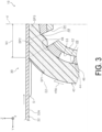
- the portion that is not substantially deformed in the +RA direction is referred to as an undeformed portion SP1
- the portion that expands into the opening 49 is referred to as an expanding portion SP2
- the portion that is compressed and does not expand is referred to as a compressed portion SP3.
- a boundary line between the undeformed portion SP1 and the expanding portion SP2 and a boundary line between the expanding portion SP2 and the compressed portion SP3 are respectively represented by dashed lines.
- the ability to clean the outer peripheral surface 32A means the ability to absorb the cleaning liquid S in the sponge 42, that is, the ability to collect the cleaning liquid S.
- the ability to collect the cleaning liquid S in the sponge 42 is higher as the density of the sponge 42 decreases. That is, as the volume of each cell of the sponge 42 increases, an amount of the cleaning liquid S contained inside the cell is increased.
- the compressed portion SP3 has a higher density of the sponge 42 than the undeformed portion SP1, the ability to collect the cleaning liquid S decreases compared to the undeformed portion SP1.
- the expanding portion SP2 is partially compressed by receiving a reaction force from the glue belt 32, the portion thereof that faces the opening 49 expands, and thus an increase in density is suppressed.
- the expanding portion SP2 suppresses the reduction in the ability to collect the cleaning liquid S compared to the undeformed portion SP1.
- the expanding portion SP2 is compressed by contact with the glue belt 32, but the ability to collect the cleaning liquid S is higher than in the compressed portion SP3. Furthermore, in the expanding portion SP2, a volume thereof increases during expansion, a negative pressure is generated, and thus the cleaning liquid S is easily sucked.
- the sponge 42 that has absorbed the cleaning liquid S is rotated in the +RA direction. Then, the sponge 42 is compressed by being sandwiched between the squeezing member 56 and the rotary member 46 while being rotated. That is, due to the sponge 42 being squeezed by the squeezing member 56, the cleaning liquid S is discharged to the outside of the sponge 42. Thus, the ability to collect the cleaning liquid S in the sponge 42 is close to collection ability in the uncompressed state before rotation.
- the transport unit 30 when the sponge 42 comes into contact with the glue belt 32, a compressed portion of the sponge 42 is generated between the support surface 48 and the glue belt 32.
- a part of the sponge 42 is released from the compressed state by expanding into the opening 49 provided in the support surface 48. That is, it is possible to create a portion less likely to be compressed in a part of the sponge 42.
- the portion less likely to be compressed has a lower density and a higher ability to absorb the cleaning liquid S than the compressed portion.
- the cleaning liquid S seeping out from the compressed portion to the glue belt 32 can be suppressed by moving the cleaning liquid S in the compressed portion of the sponge 42 to the inside of the portion less likely to be compressed.
- the sponge 42 since the sponge 42 is compressed when the cleaning liquid S is removed from the glue belt 32, a seeping-out action of returning the cleaning liquid S to the glue belt 32 is more likely to occur rather than an action of absorbing the cleaning liquid S.
- the sponge 42 driven to rotate in which the rotary member 46 rotates in accordance with the transport operation of the glue belt 32 the seeping-out of the cleaning liquid S onto the glue belt 32 occurs more conspicuously than a configuration using the sponge 42 that is not rotated.
- the transport unit 30 even when the sponge 42 driven to rotate is used, a part of the sponge 42 expands into the opening 49, and thus the state of the sponge 42 changes from the compressed state to the released state. Thus, since the density of the sponge 42 is reduced, and thus the ability to absorb the cleaning liquid S is ensured, the decrease in the ability of the sponge 42 to clean the outer peripheral surface 32A of the glue belt 32 can be suppressed.
- the communication port 54 is located in the second region A2 rather than the first region A1, and thus the state of the sponge 42 is maintained in the compressed state.
- the sponge 42 in contact with the squeezing member 56 is less likely to be released from the compressed state, and thus, it is possible to suppress a decrease in the ability to squeeze the sponge 42 with the squeezing member 56.
- a part of the sponge 42 released from the compressed state in the opening 49 expands further to the inside of the shaft member 52 due to the negative pressure generated by the suction unit 64 inside the shaft member 52.
- the sponge 42 can easily absorb the cleaning liquid S, the ability to collect the cleaning liquid S in a part of the sponge 42 can be further enhanced.
- the printer 10 when the sponge 42 comes into contact with the glue belt 32, a compressed portion of the sponge 42 is generated between the support surface 48 and the glue belt 32.
- a part of the sponge 42 is released from the compressed state by expanding into the opening 49 provided in the support surface 48. That is, it is possible to create the portion less likely to be compressed in a part of the sponge 42.
- This portion less likely to be compressed has a lower density and a higher ability to absorb the cleaning liquid S than the compressed portion.
- the cleaning liquid S seeping outward from the compressed portion can be suppressed by moving the cleaning liquid S that seeps out from the compressed portion of the sponge 42 to the portion less likely to be compressed.
- a transport unit 70 according to a second embodiment is specifically described. Note that configurations similar to those of the printer 10 and the transport unit 30 of the first embodiment are denoted by the same reference numerals, and descriptions thereof will be omitted.
- the transport unit 70 is provided in the printer 10 in place of the transport unit 30 ( FIG. 1 ).
- the configuration other than the transport unit 70 in the printer 10 is similar to the configuration of the first embodiment.
- the transport unit 70 is an example of a transport device that transports a medium M.
- the transport unit 70 includes a shaft member 72 instead of the shaft member 52 ( FIG. 2 ) in the transport unit 30. Since the configuration other than the shaft member 72 is the same as the configuration of the transport unit 30, the description thereof will be omitted.
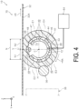
- the shaft member 72 has a configuration in which a communication port 74 is added to the shaft member 52. Since the configuration other than the communication port 74 is the same as the configuration of the shaft member 52, the description thereof will be omitted. As an example, the communication port 54 and the communication port 74 arranged in the +RA direction are provided in the outer peripheral surface 53.
- the communication port 74 is located downstream from the communication port 54 in the +RA direction.
- the communication port 54 and the communication port 74 are substantially line-symmetrical with respect to the vertical line V when seen in the +X direction.
- a size of the communication port 74 is substantially the same as that of the communication port 54.
- the communication port 74 can be brought into communication with one opening 49 as the rotary member 46 rotates.
- the communication port 74 allows communication between the inside and the outside of the shaft member 52.
- the communication port 74 is located inside the region E1 when seen in the +X direction.
- the communication port 74 is located a position closer to the vertical line V than the lateral line H inside the region E1.
- the communication port 74 is provided in the second region A2 ( FIG. 2 ).
- An opening width of the communication port 74 in the +RA direction is substantially equal to an opening width of the opening 49 in the +RA direction, as an example.
- a portion of the sponge 42 that faces the communication port 74 and the opening 49 which are in a communicated state is located inside the downstream region N2 and is gradually released from the compressed state along with rotation.
- the portion that is inside the downstream region N2 and expands into the opening 49 is distinguished as an expanding portion SP4.
- a boundary line between the undeformed portion SP1 and the expanding portion SP4 and a boundary line between the expanding portion SP4 and the compressed portion SP3 are respectively represented by dashed lines.
- the expanding portion SP4 Since a distance between the expanding portion SP4 and the glue belt 32 increases toward the downstream in the +RA direction, the expanding portion SP4 is gradually released from the compressed state along with rotation. Furthermore, a portion of the expanding portion SP4 that faces the opening 49 expands, and thus a density thereof is reduced. Thus, since a volume of the expanding portion SP4 is increased during expansion, and thus a negative pressure is generated, the cleaning liquid S can be easily sucked.
- the ability to collect the cleaning liquid S can be enhanced by applying a negative pressure to the sponge 42 in a portion of the downstream region N2 in which the communication port 74 is provided.
- the cleaning liquid S collected in the compressed portion SP3 adhering again to the outer peripheral surface 32A in the expanding portion SP4 can be suppressed.
- a transport unit 80 according to a third embodiment is specifically described. Note that the same reference numerals are assigned to the same configurations as those of the printer 10 and the transport units 30 and 70 of the first and second embodiments, and the description thereof will be omitted.
- the transport unit 80 is provided in the printer 10 in place of the transport unit 30 ( FIG. 1 ).
- the configuration other than the transport unit 80 in the printer 10 is similar to the configuration of the first embodiment.
- the transport unit 80 is an example of a transport device that transports a medium M.
- the transport unit 80 includes a glue belt 32, a cleaning unit 36, a sponge 82, and a support unit 84.
- a cleaning blade 92, a collection tank 94, and a suction unit 96 are also provided in the transport unit 80.
- the sponge 82 is provided at a position at which it faces the lower surface portion 34C in the -Z direction and at a position at which is located downstream of the cleaning unit 36 in the +R direction, that is, in the -Y direction.
- the sponge 82 is a prismatic member that extends in the X direction.
- the sponge 82 is a porous elastic body and has an open cell structure consisting of a plurality of cells not illustrated. Each of the cells functions as a chamber capable of accommodating the cleaning liquid S.
- An upper surface 83 of the sponge 82 in the +Z direction is located along an X-Y plane. The entire upper surface 83 comes into contact with the outer peripheral surface 32A.
- the sponge 82 When the sponge 82 is compressed in a state in which air and the cleaning liquid S are accommodated in each of the cells, the air and the cleaning liquid S inside of each of the cells is discharged to the outside. Note that when the sponge 82 is compressed, some of the air and the cleaning liquid S may move to other cells, and some of the air and the cleaning liquid S may remain inside the sponge 82. Also, when the sponge 82 returns from the compressed state to the uncompressed state, a negative pressure is generated inside each of the cells, and thus the air and the cleaning liquid S can be absorbed.
- the sponge 82 is supported by the support unit 84 which will be described below.
- the upper surface 83 of the sponge 82 is in contact with the outer peripheral surface 32A cleaned by the cleaning unit 36.
- the sponge 82 is fixed to the support unit 84. Therefore, the glue belt 32 slides against the sponge 82. Also, the sponge 82 is in the compressed state of being compressed in the Z direction by being sandwiched between the support unit 44 and the glue belt 32.
- the support unit 84 is configured to include, for example, a chamber 86 and a bracket (not illustrated) that fixes the chamber 86 to a portion of the device main body 12 ( FIG. 1 ).
- the chamber 86 is a hollow member that extends in the X direction.
- the chamber 86 includes an upper wall 87 that constitutes a ceiling portion of the chamber 86.
- the upper wall 87 includes a support surface 88 that is an upper surface in the +Z direction.
- the support surface 88 is a plane along the X-Y plane as an example. Openings 89A, 89B, and 89C are provided in the support surface 88. A lower surface 85 of the sponge 82 in the -Z direction is bonded to a portion of the support surface 88 other than the openings 89A, 89B, and 89C. In this way, the support unit 84 includes the support surface 88 capable of supporting the sponge 82.
- the openings 89A, 89B, and 89C are arranged and are spaced apart in the Y direction when seen in the +X direction.
- Each of the openings 89A, 89B, and 89C is provided as an end portion of a through hole that passes through the upper wall 87 in the Z direction.
- each of the openings 89A, 89B, and 89C is provided in a slit shape that extends in the X direction.
- the opening 89A is located in the +Y direction from the center of the upper wall 87 in the Y direction.
- a length of the opening 89A in the Y direction is L1 (mm).
- the opening 89B is located at the center of the upper wall 87 in the Y direction.
- a length of the opening 89B in the Y direction is L2 (mm).
- the opening 89C is located in the -Y direction from the center of the upper wall 87 in the Y direction.
- a length of the opening 89C in the Y direction is L3 (mm).
- a plurality of openings 89A, 89B, and 89C may be provided at intervals not only in the Y direction but also in the X direction.
- the number of openings provided in the support surface 88 is not limited to three, and may be singular or plural.
- the openings provided in the support surface 88 are not limited to those in which each has a different length in the Y direction, and may be those in which all have the same length in the Y direction, or may be those in which some have the same length and the rest has a different length.
- the cleaning blade 92 is located in the -Y direction with respect to the sponge 82 and downstream in the +R direction. A tip end portion of the cleaning blade 92 comes into contact with the outer peripheral surface 32A. In this way, the cleaning blade 92 is capable of collecting foreign matter, and the like that are not collected by the sponge 82.
- the collection tank 94 is formed in a box shape that opens in the +Z direction.
- the collection tank 94 covers a part of the sponge 82, the chamber 86, and a part of the cleaning blade 92 when seen in the +X direction.
- the collection tank 94 can collect the cleaning liquid S and the like that flows down along the side of the sponge 82 and the cleaning liquid S and the like scraped by the cleaning blade 92.
- the suction unit 96 sucks a gas inside the chamber 86.
- the gas includes not only air, but also gas other than air.
- the suction unit 96 is coupled to the chamber 86.
- an internal state of the chamber 86 is brought into a negative pressure state by rotating a fan (not illustrated).
- the suction unit 96 can change the negative pressure by changing an air volume. That is, the suction unit 96 can perform absorption to an extent that a part of the sponge 82 expands into the openings 89A, 89B, and 89C.
- the suction unit 96 includes a collection unit (not illustrated). Additionally, the suction unit 96 is configured to be able to collect the cleaning liquid S and the like sucked inside the chamber 86 during suction at the collection unit.
- the sponge 82 collects the cleaning liquid S and the like adhering to the outer peripheral surface 32A by coming into contact with the outer peripheral surface 32A after cleaning by the cleaning unit 36. Specifically, the cleaning liquid S and the like permeate the inside of the sponge 82, and thus the cleaning liquid S is collected in the sponge 82.
- the cleaning liquid S and the like collected in the sponge 82 flow down inside the sponge 82 in the -Z direction due to an action of its own weight and an action of absorption by the suction unit 96.
- the portions of the sponge 82 that face the openings 89A, 89B, 89C expand into the openings 89A, 89B, and 89C and the chamber 86 due to the action of the negative pressure.
- the density of the sponge 82 decreases over almost the entirety thereof in the Z direction. That is, in the portion of the sponge 82 that expands, since an amount of the cleaning liquid S that can be held increases due to an increase in volume during expansion, it is possible to suppress movement of some of the cleaning liquid S from the sponge 82 to the outer peripheral surface 32A.
- the transport unit 80 when the sponge 82 comes into contact with the glue belt 32, a compressed portion of the sponge 82 is generated between the support surface 88 and the glue belt 32.
- a part of the sponge 82 expands into the openings 89A, 89B, and 89C provided in the support surface 88 and is thus released from the compressed state. That is, it is possible to create a portion less likely to be compressed in a part of the sponge 82.
- the portion less likely to be compressed has a lower density and a higher ability to absorb the cleaning liquid S than the compressed portion.
- the cleaning liquid S seeping out from the compressed portion to the glue belt 32 can be suppressed by moving the cleaning liquid S in the compressed portion of the sponge 82 to the inside of the portion less likely to be compressed.
- the state of the end portion in the -Z direction that is a part of the sponge 82 is released from the compressed state in the openings 89A, 89B, and 89C, and thus a part of the sponge 82 expands into the openings. Furthermore, a part of the sponge 82 expands further into the chamber 86 as the gas inside the chamber 86 is sucked by the suction unit 96. Therefore, a density of a part of the sponge 82 is reduced, and the ability to absorb the cleaning liquid S is increased. That is, since the sponge 82 is more likely to absorb the cleaning liquid S, the ability to collect the cleaning liquid S can be enhanced in a part of the sponge 82.
- the lengths L1, L2, and L3 of the openings 89A, 89B, and 89C in the Y direction increase in order toward the downstream direction in the +R direction.
- the ability of the sponge 82 to collect the cleaning liquid S is enhanced toward the downstream in the +R direction.
- a portion of the sponge 82 that is deformed in the +R direction and a portion in the vicinity of the portion are likely to be maintained in a state in which the ability to collect the cleaning liquid S is relatively high. Therefore, the cleaning liquid S and the like are less likely to remain on the outer peripheral surface 32A.
- a transport unit 100 according to a fourth embodiment is specifically described. Note that configurations similar to those of the printer 10 and the transport units 30, 70, and 80 of the first, second, and third embodiments are denoted by the same reference numerals, and the descriptions thereof will be omitted.
- the transport unit 100 is provided in the printer 10 in place of the transport unit 30 ( FIG. 1 ).
- the configuration other than the transport unit 100 in the printer 10 is similar to the configuration in the first embodiment.
- the transport unit 100 is an example of a transport device that transports a medium M.
- the transport unit 100 includes a glue belt 32, a cleaning unit 36, a sponge 82, and a support member 102, and a lifting unit 108.
- a cleaning blade 92 and a collection tank 94 are also provided in the transport unit 100.
- the sponge 82 is provided at a position at which it faces the lower surface portion 34C in the -Z direction and at a position at which it located downstream of the cleaning unit 36 in the +R direction, that is, in the -Y direction.
- the entire upper surface 83 comes into contact with the outer peripheral surface 32A.
- the sponge 82 is supported on a support surface 104 of the support member 102 which will be described below. Also, the sponge 82 can be compressed in the Z direction by being sandwiched between the support member 102 and the glue belt 32.
- the glue belt 32 slides against the sponge 82.
- a lower surface 85 is deformed into a shape different from a shape along an X-Y plane.
- the lower surface 85 after deformation includes a planar portion 85A along the X-Y plane when seen in the +X direction and an inclined portion 85B that extends in an oblique direction intersecting the Y direction.
- the planar portion 85A is provided at four locations on the lower surface 85 as an example.
- the inclined portion 85B is provided at three locations on the lower surface 85 as an example. Note that the entire lower surface 85 may be constituted by one inclined portion 85B.
- planar portion 85A located at the end portion in the -Y direction is adhered to the support surface 104 which will be described below.
- the support member 102 is an example of the support unit including the support surface 104 capable of supporting the sponge 82.
- the support member 102 is longer in the X direction than the glue belt 32.
- the support member 102 includes vertical wall portions 102A, 102B, 102C, and 102D, and pairs of side wall portions 103A, 103B, and 103C that couple both ends in the X direction of each of the vertical wall portions 102A, 102B, 102C, and 102D in the Y direction when seen in the +X direction.
- An interval between the pair of side wall portions 103A in the X direction may be greater than or equal to a dimension of the sponge 82 in the X direction.
- the pairs of side wall portions 103B and 103C are also similar.
- the vertical wall portion 102A is a portion located at an end portion of the support member 102 in the +Y direction and extending in the +Z direction.
- the vertical wall portion 102B is located in the -Y direction with an interval from the vertical wall portion 102A and extends in the +Z direction.
- the vertical wall portion 102B is higher in the +Z direction than the vertical wall portion 102A.
- the vertical wall portion 102C is located in the -Y direction with an interval from the vertical wall portion 102B and extends in the +Z direction.
- the vertical wall portion 102C is higher in the +Z direction than the vertical wall portion 102B.
- the vertical wall portion 102D is located in the -Y direction with an interval from the vertical wall portion 102C and extends in the +Z direction.
- the vertical wall portion 102D is higher in the +Z direction than the vertical wall portion 102C.
- the support member 102 has a shape with a plurality of steps at an upper end in the +Z direction.
- the support surface 104 is an upper surface of the support member 102 in the +Z direction.
- the support surface 104 includes at least a plane 104A, a plane 104C, a plane 104E, and a plane 104G.
- openings 106A, 106B, and 106C are provided in the support surface 104.
- the support member 102 includes an inclined surface 104B, an inclined surface 104D, and an inclined surface 104F.
- the plane 104A is an upper surface of the vertical wall portion 102A.
- the inclined surface 104B is an upper surface of the side wall potion 103A.
- the plane 104C is an upper surface of the vertical wall portion 102B.
- the inclined surface 104D is an upper surface of the side wall portion 103B.
- the plane 104E is an upper surface of the vertical wall portion 102C.
- the inclined surface 104F is an upper surface of the side wall portion 103C.
- the plane 104G is an upper surface of the vertical wall portion 102D.
- an end portion of the lower surface 85 in the -Y direction is bonded to the plane 104G as an example. Also, the lower surface 85 is not bonded to the plane 104A, the inclined surface 104B, the plane 104C, the inclined surface 104D, the plane 104E, and the inclined surface 104F.
- the sponge 82 Before the sponge 82 is compressed in the Z direction, only an end portion of the lower surface 85 in the -Y direction is supported by the support member 102. Also, the sponge 82 is supported by the support member 102 except for the portions facing the openings 106A, 106B, and 106C in a state in which it is compressed in the Z direction.
- the opening 106A is provided between the vertical wall portion 102A and the vertical wall portion 102B when seen in the +X direction.
- the opening 106A is provided as an end portion of a through hole that passes through the support member 102 in the Z direction.
- the opening 106A is provided in a slit shape that extends in the X direction.
- the side wall portion 103A is located outside the opening 106A in the X direction.
- a length of the opening 106A in the Y direction is L4 (mm).
- the opening 106B is provided between the vertical wall portion 102B and the vertical wall portion 102C when seen in the +X direction.
- the opening 106B is provided as an end portion of a through hole that passes through the support member 102 in the Z direction.
- the opening 106B is provided in a slit shape that extends in the X direction.
- the side wall portion 103B is located outside the opening 106B in the X direction.
- a length of the opening 106B in the Y direction is L5 (mm).
- the opening 106C is provided between the vertical wall portion 102C and the vertical wall portion 102D when seen in the +X direction.
- the opening 106C is provided as an end portion of a through hole that passes through the support member 102 in the Z direction.
- the opening 106C is provided in a slit shape that extends in the X direction.
- the side wall portion 103C is located outside the opening 106C in the X direction.
- a length of the opening 106C in the Y direction is L6 (mm).
- L4 ⁇ L5 ⁇ L6.
- a plurality of openings 106A, 106B, and 106C may be provided at intervals not only in the Y direction but also in the X direction.
- the number of openings provided in the support surface 104 is not limited to three, and may be singular or plural.
- the openings provided in the support surface 104 are not limited to those in which each has a different length in the Y direction, and may be those in which all have the same length in the Y direction, or may be those in which some have the same length and the rest has a different length.
- the lifting unit 108 includes a cam and a motor which are not illustrated. As an example, the lifting unit 108 supports both end portions of the support member 102 in the X direction. A lifting operation of the lifting unit 108 is controlled by the control unit 20 ( FIG. 1 ).
- the support member 102 In an initial state before the lifting unit 108 is operated, the support member 102 is at a lowered position in the -Z direction. In this state, the lower surface 85 is along the X-Y plane as indicated by an alternated long and short dash line T.
- the support member 102 moves upward in the +Z direction by operating the lifting unit 108.
- a portion of the sponge 82 that does not face the openings 106A, 106B, and 106C is in the compressed state in the Z direction by being sandwiched between the glue belt 32 and the support member 102.
- portions of the sponge 82 that face the openings 106A, 106B, and 106C are in the released state and are thus less likely to be compressed.
- the portions of the sponge 82 that face the openings 106A, 106B, and 106C expand into the openings 106A, 106B, and 106C as the support member 102 moves upward.
- the sponge 82 collects the cleaning liquid S and the like adhering to the outer peripheral surface 32A by coming into contact with the outer peripheral surface 32A after cleaning by the cleaning unit 36.
- the density of the sponge 82 decreases over almost the entirety thereof in the. That is, since a volume of the portion of the sponge 82 that expands increases during expansion, and the amount of cleaning liquid S that can be held increases, it is possible to suppress movement of some of the cleaning liquid S from the sponge 82 to the glue belt 32.
- the transport unit 100 when the sponge 82 comes into contact with the glue belt 32, a compressed portion of the sponge 82 is generated between the support surface 104 and the glue belt 32.
- a part of the sponge 82 is released from the compressed state by expanding into the openings 106A, 106B, and 106C provided in the support surface 104. That is, it is possible to create a portion less likely to be compressed in a part of the sponge 82.
- the portion less likely to be compressed has a lower density and a higher ability to absorb the cleaning liquid S than the compressed portion.
- the cleaning liquid S seeping out from the compressed portion to the glue belt 32 can be suppressed by moving the cleaning liquid S in the compressed portion of the sponge 82 to the inside of the portion less likely to be compressed.
- the lengths L4, L5, and L6 of the openings 106A, 106B, and 106C in the Y direction increase in order toward the downstream direction in the +R direction.
- the ability of the sponge 82 to collect the cleaning liquid S is enhanced toward the downstream in the +R direction.
- a portion of the sponge 82 that is deformed in the +R direction and a portion in the vicinity of the portion are likely to be maintained in a state in which the ability to collect the cleaning liquid S is relatively high. Therefore, the cleaning liquid S and the like are less likely to remain on the outer peripheral surface 32A.
- the support member 102 in a so-called maintenance mode in which the printer 10 does not perform recording, can be moved up and down in the Z direction as the glue belt 32 moves.
- a negative pressure is generated inside the sponge 82 by transition of the sponge 82 from the compressed state to the released state, and thus the cleaning liquid S can be easily collected compared to a configuration in which the support member 102 does not move up and down.
- heights of the vertical wall portions 102A, 102B, 102C, 102D are different from each other, and the height of the vertical wall portion 102D is the highest. Therefore, when the support member 102 moves up and down in the Z direction, a degree of compression of the sponge 82 is the highest at a downstream end in the +R direction and the vicinity thereof and is the lowest at an upstream end and the vicinity thereof. Thus, the cleaning liquid S collected in a downstream portion of the sponge 82 in the +Y direction easily flows to the upstream portion which has a larger volume than the downstream portion. Due to such actions, it is possible to suppress movement of the cleaning liquid S collected in the sponge 82 from the downstream portion of the sponge 82 in the +R direction to the glue belt 32.
- transport units 30, 70, 80, and 100 and the printer 10 according to the first, second, third, and fourth embodiments of the present disclosure are basically configured as described above, it is also possible to change, omit, or combine partial configurations without departing from the gist of the present disclosure. Hereinafter modified examples are described.
- a drive unit for driving the rotary member 46 may be provided to rotate the rotary member 46 in a direction opposite to the +RA direction.
- the communication port 74 may be provided instead of the communication port 54.
- one of the plurality of communication ports may be provided in the first region A1.
- the shaft member 52 may be a solid, that is, a cylindrical member. Also, a recess portion may be provided in an outer peripheral portion of the solid shaft member, and the solid shaft member may be disposed such that the recess portion and the opening are brought into communication with each other. For example, when a thickness of the rotary member 46 in the radial direction is relatively thin, a space is increased by the recess portion in a position at which the recess portion and the opening are brought into communication with each other, and thus the sponge 42 can easily expand.
- An opening area of the communication port 54 may be changed by movably providing a shutter member in the shaft member 52.
- the transport unit 70 may be configured to include only the communication port 74 without the communication port 54. Furthermore, the drive unit for driving the rotary member 46 may be provided to rotate the rotary member 46 in the direction opposite to the +RA direction. The opening area of the communication port 54 and the communication port 74 may be changed by movably providing the shutter member in the shaft member 72.
- the opening area of the openings 89A, 89B, and 89C may be changed by providing the shutter member in the chamber 86.
- the openings 49 may include those having different lengths in the +RA direction.
- the openings 49, the openings 89A, 89B, and 89C and the openings 106A, 106B, and 106C are not limited to those forming openings of through holes, and may be those forming openings of bottomed recess portions.
- the openings 49, the openings 89A, 89B, and 89C and the openings 106A, 106B, and 106C may be configured as openings between adjacent protruding portions.
Landscapes
- Engineering & Computer Science (AREA)
- Mechanical Engineering (AREA)
- Ink Jet (AREA)
- Handling Of Sheets (AREA)
- Feeding Of Articles By Means Other Than Belts Or Rollers (AREA)
Abstract
Description
- The present application is based on, and claims priority from
JP Application Serial Number 2022-024772, filed February 21, 2022 - The present disclosure relates to a transport device and a droplet ejecting device.
- An image recording device of
JP-A-2020-200120 - In such a configuration in which a sponge is pressed against an outer peripheral surface of a transport belt, as in the image recording device according to
JP-A-2020-200120 - In order to solve the problem described above, the transport device according to the present disclosure includes a transport member configured to transport a medium, a cleaning unit configured to clean the transport member with a liquid, and a support unit including a support surface configured to support a sponge that comes into contact with the transport member cleaned by the cleaning unit, wherein at least one opening is provided in the support surface.
- In order to solve the problem described above, a droplet ejecting device according to the present disclosure includes an ejecting unit configured to eject a droplet on a medium, a transport member configured to transport the medium, a cleaning unit configured to clean the transport member with a liquid, and a support unit including a support surface configured to support a sponge that comes into contact with the transport member cleaned by the cleaning unit, wherein at least one opening is provided in the support surface.
-
-
FIG. 1 is a schematic diagram of an internal structure of a printer according to a first embodiment. -
FIG. 2 is a schematic diagram of a cleaning unit and surroundings thereof in the printer according to the first embodiment. -
FIG. 3 is an enlarged schematic diagram of a sponge and a glue belt of the printer according to the first embodiment. -
FIG. 4 is a schematic diagram of a cleaning unit and surroundings thereof in a printer according to a second embodiment. -
FIG. 5 is an enlarged schematic diagram of a sponge and a glue belt of the printer according to the second embodiment. -
FIG. 6 is a schematic diagram of a cleaning unit of a printer according to a third embodiment. -
FIG. 7 is a schematic diagram of a cleaning unit of a printer according to a fourth embodiment. - Hereinafter, the present disclosure will be schematically described.
- A transport device according to a first aspect includes a transport member configured to transport a medium, a cleaning unit configured to clean the transport member with a liquid, and a support unit including a support surface configured to support a sponge that comes into contact with the transport member cleaned by the cleaning unit, wherein at least one opening is provided in the support surface.
- According to this aspect, when the sponge comes into contact with the transport member, a compressed portion of the sponge is generated between the support surface and the transport member. Here, a portion of the sponge is released from the compressed state by expanding into the opening provided in the support surface. That is, it is possible to create a portion less likely to be compressed in a part of the sponge. The portion less likely to be compressed has a lower density and a higher ability to absorb the liquid than the compressed portion. Additionally, the liquid in the portion of the sponge that is compressed is internally moved into the portion less likely to be compressed, and thus the liquid seeping out from the compressed portion to the transport member can be suppressed. Thus, it is possible to suppress a decrease in the ability of the sponge to clean the outer peripheral surface of the transport member.
- According to a transport device of the second aspect, in the first aspect, the support unit is a rotatable rotary member, and the sponge is provided on the outer periphery of the rotary member, is pressed against the transport member, and is configured to be driven to rotate with respect to the transport member.
- Since the sponge is compressed when the liquid is removed from the transport member, a seeping-out action of returning the liquid to the transport member is likely to occur rather than an action of absorbing the liquid in the sponge. Here, in the sponge driven to rotate in which the rotary member rotates in accordance with a transport operation of the transport member, the seeping-out of the liquid to the transport member occurs more conspicuously than in a configuration using a sponge that is not rotated.
- According to this aspect, even when the sponge that is driven to rotate is used, a state of the sponge changes from the compressed state to the released state as a part of the sponge expands into the opening. Thus, since the ability to absorb the liquid is ensured by lowering the density of the sponge, it is possible to suppress a decrease in the ability of the sponge to clean the outer peripheral surface of the transport member.
- According to a transport device of a third aspect, in the second aspect, the rotary member is a tubular member including an inner peripheral surface, a shaft member that includes an outer peripheral surface facing the inner peripheral surface and that rotatably supports the rotary member, and a squeezing member that squeezes the sponge by pressing the sponge are provided, at least one communication port brought into communication with the at least one opening as the rotary member rotates is provided in the outer peripheral surface, and when a region of the outer peripheral surface aligned with the squeezing member in the radial direction of the rotary member is referred to as a first region, and a region of the outer peripheral surface shifted in the rotational direction of the rotary member with respect to the first region is referred to as a second region, the communication port is provided in the second region.
- According to this aspect, when the sponge comes into contact with the squeezing member, the communication port is located in the second region rather than the first region, and thus the state of the sponge is maintained in the compressed state. Thus, the sponge that comes into contact with the squeezing member is less likely to be released from the compressed state, and thus it is possible to suppress a decrease in ability to squeeze the sponge with the squeezing member.
- According to a transport device of a fourth aspect, in the third aspect, the shaft member is a tubular member, a negative pressure generating unit that generates a negative pressure inside the shaft member is provided, and the communication port allows communication between the inside and the outside of the shaft member.
- According to this aspect, a part of the sponge that is released from the compressed state in the opening further expands into the inside of the shaft member by the negative pressure inside the shaft member generated by the negative pressure generating unit. Thus, since the sponge easily absorbs the liquid, it is possible to further increase the ability to collect the liquid in a part of the sponge.
- According to a transport device of a fifth aspect, in the first aspect, the support unit includes a chamber, and a suction unit that sucks a gas inside the chamber is included.
- According to this aspect, the state of a part of the sponge is released from the compressed state in the opening, and thus a part of the sponge expands into the inside of the opening. Furthermore, the state of a part of the sponge is a state in which the gas inside the chamber is sucked by the suction unit, and thus a part of the sponge further expands into the inside of the chamber. Therefore, the density of a part of the sponge is reduced, and the ability to absorb the liquid is increased. That is, since the sponge is more likely to absorb the liquid, it is possible to further enhance the ability to collect the liquid in a part of the sponge.
- A droplet ejecting device according to a sixth aspect includes an ejecting unit configured to eject a droplet on a medium, a transport member configured to transport the medium, a cleaning unit configured to clean the transport member with a liquid, and a support unit including a support surface configured to support a sponge that comes into contact with the transport member cleaned by the cleaning unit, wherein at least one opening is provided in the support surface.
- According to this aspect, when the sponge comes into contact with the transport member, a compressed portion of the sponge is generated between the support surface and the transport member. Here, a part of the sponge is released from the compressed state by expanding into the opening provided in the support surface. That is, it is possible to create a portion less likely to be compressed in a part of the sponge. The portion less likely to be compressed has a lower density and a higher ability to absorb the liquid than a compressed portion. Additionally, the liquid seeping outward from the compressed portion can be suppressed by moving the liquid that seeps out of the compressed portion of the sponge to the portion less likely to be compressed. Thus, it is possible to suppress a decrease in the ability of the sponge to clean the outer peripheral surface of the transport member.
- Hereinafter, a
printer 10, which is an example of a droplet ejecting device according to a first embodiment of the present disclosure, and atransport unit 30 will be described in detail. - As illustrated in
FIG. 1 , theprinter 10 is installed on afloor 2 of afactory 1. Theprinter 10 performs recording on a medium M with arecording unit 22 which will be described below. Examples of the medium M include fabrics and paper. Also, the medium M is drawn from a front surface of theprinter 10 as an example. Note that an X-Y-Z coordinate system illustrated in each of the drawings is an orthogonal coordinate system. - An X direction is a device width direction of the
printer 10 and is a horizontal direction. When theprinter 10 is seen from the front, a direction toward the left in the X direction is a +X direction, and a direction toward the right is a -X direction. Also, the X direction corresponds to a width direction of the medium M. - A Y direction is a depth direction of the
printer 10, and is the horizontal direction. When theprinter 10 is seen from the front, a forward direction is a +Y direction, and the rearward direction is the -Y direction. - A Z direction is along a gravity direction in which gravity acts. An upward direction in the Z direction is a +Z direction, and a downward direction is a -Z direction. The +Z direction is a device height direction of the
printer 10. - The
printer 10 includes a devicemain body 12, amain body cover 14, atransport unit 30, acontrol unit 20, arecording unit 22, and an operation unit (not illustrated) which will be described below. - The device
main body 12 is configured as a base portion on which each unit of theprinter 10 is provided. A drivingroller 16, a drivenroller 18, and a motor (not illustrated) are provided as an example of a driving unit in the devicemain body 12. - The driving
roller 16 is disposed downstream in the +Y direction in the devicemain body 12. The drivenroller 18 is disposed upstream in the +Y direction. Both the drivingroller 16 and the drivenroller 18 have rotation axes along the X direction. Rotation of the drivingroller 16 is controlled by thecontrol unit 20 which will be described below. - The
main body cover 14 is an exterior member that covers each unit of theprinter 10. - The operation unit includes a touch panel (not illustrated) and an operation button. In the operation unit, an operation of each unit of the
printer 10 can be set and operated. - The
control unit 20 includes a central processing unit (CPU) functioning as a computer, a memory, and a storage. In part of the memory, a program can be developed. Illustrations of the CPU, the memory and the storage will be omitted. Thecontrol unit 20 executes a program to control various operations such as transportation, recording, discharging, cleaning, and the like in each unit of theprinter 10. - The
recording unit 22 is provided in the devicemain body 12. Also, therecording unit 22 performs recording on the medium M moving in the +Y direction using an ink K as an example of a recording material. Specifically, therecording unit 22 includes arecording head 24 and acarriage 26 that supports therecording head 24. - The
carriage 26 includes a motor (not illustrated) and the like and supports therecording head 24. Also, thecarriage 26 is configured to reciprocate therecording head 24 in the X direction. - The
recording head 24 includes a plurality of nozzles (not illustrated) and is disposed in the +Z direction with respect to aglue belt 32 which will be described below. Therecording head 24 is an example of an ejecting unit capable of ejecting ink droplets Q as an example of a droplet on the medium M. An image can be recorded on the medium M by ejecting ink droplets Q onto the medium M from therecording head 24. - The medium M is an example of a recording medium on which an image is recorded.
- The
transport unit 30 is an example of a transport device that transports the medium M. Thetransport unit 30 includes aglue belt 32, acleaning unit 36, asponge 42, and a support unit 44 (FIG. 2 ). A shaft member 52 (FIG. 2 ), a squeezingmember 56, acleaning blade 58, acollection tank 62, and a suction unit 64 (FIG. 2 ) are also provided in thetransport unit 30. - The
glue belt 32 is an example of a transport member capable of transporting the medium M, and is configured as an endless belt formed by joining both ends of an elastic flat plate. Theglue belt 32 is a rubber belt. Also, theglue belt 32 is wound around the drivingroller 16 and the drivenroller 18. In other words, theglue belt 32 is provided in the devicemain body 12, and the medium M can be transported in the +Y direction by being moved circularly. A direction of rotation of theglue belt 32 is a +R direction. Theglue belt 32 includes an outerperipheral surface 32A. - As an example, the outer
peripheral surface 32A is coated with an adhesive (not illustrated) to have adhesiveness, and is capable of supporting and adsorbing the medium M. The "adhesiveness" refers to a property of temporarily adhering to other members and allowing separation from an adhesion state. - A portion of the outer
peripheral surface 32A located in the +Z direction from the center of the drivingroller 16 and along an X-Y plane is referred to as anupper surface portion 34A. Theupper surface portion 34A supports the medium M. A portion of the outerperipheral surface 32A wound around the drivingroller 16 is referred to as acurved surface portion 34B. A portion of the outerperipheral surface 32A located in the -Z direction from the center of the drivingroller 16 and along the X-Y plane is referred to as alower surface portion 34C. A portion of the outerperipheral surface 32A wound around the drivenroller 18 is referred to as acurved surface portion 34D. - A
pressure roller 29 is provided at a position that faces an end portion of theupper surface portion 34A in the -Y direction in the +Z direction. Thepressure roller 29 presses the medium M against the outerperipheral surface 32A. - After the medium M is pressed against the outer
peripheral surface 32A, theglue belt 32 is moved in the +Y direction to face therecording unit 22. Then, recording is performed on the medium M by therecording unit 22. The medium M recorded by therecording unit 22 is wound by a winding roller (not illustrated) and is then separated from thecurved surface portion 34B. - The
cleaning unit 36 can clean theglue belt 32 with a cleaning liquid S which is an example of the liquid. Thecleaning unit 36 is provided at a position at which it faces an end portion of thelower surface portion 34C in the +Y direction in the -Z direction. Thecleaning unit 36 cleans theglue belt 32 after the medium M is separated with the cleaning liquid S, thereby removing the ink K, fibers, and the like adhering to the outerperipheral surface 32A. As an example, thecleaning unit 36 includes acleaning tank 37, abrush roller 38, and a motor (not illustrated) that drives thebrush roller 38 to be rotated. - The
cleaning tank 37 is formed in a box shape that opens in the +Z direction. The cleaning liquid S is stored inside thecleaning tank 37. - The
brush roller 38 is rotated about a rotary shaft (not illustrated) that extends in the X direction. Both end portions of the rotary shaft in the X direction are supported by thecleaning tank 37. A part of the outer periphery of thebrush roller 38 in the -Z direction from a center thereof is immersed in the cleaning liquid S. Also, a part of the outer periphery of thebrush roller 38 in the +Z direction from the center thereof is in contact with the outerperipheral surface 32A. A length of thebrush roller 38 in the X direction is the same as or slightly longer than a length of theglue belt 32 in the X direction. - The
sponge 42 is provided at a position at which it faces thelower surface portion 34C in the -Z direction and a position at which it is located downstream in the +R direction with respect to thecleaning unit 36, that is, in the -Y direction. Thesponge 42 is a cylindrical member having a central axis that extends in the X direction. Thesponge 42 is a porous elastic body and has an open cell structure consisting of a plurality of cells not illustrated. Each of the cells functions as a chamber capable of accommodating the cleaning liquid S. - When the
sponge 42 is compressed in a state in which air and the cleaning liquid S are accommodated inside each of the cells, the air and the cleaning liquid S inside each of the cells are discharged to the outside. Note that when thesponge 42 is compressed, some of the air and the cleaning liquid S may move to other cells, and thus some of the air and the cleaning liquid S may remain inside thesponge 42. - Also, when the state of the
sponge 42 returns from a compressed state to an uncompressed state, a negative pressure is generated inside each of the cells, and thus the air and the cleaning liquid S can be absorbed. - As illustrated in
FIG. 2 , thesponge 42 is supported by asupport unit 44 which will be described below. Thus, a part of thesponge 42 can come into contact with theglue belt 32 cleaned by thecleaning unit 36. Specifically, thesponge 42 is provided on the outer periphery of arotary member 46 which will be described below, is pressed against theglue belt 32 and can be driven to rotate with respect to theglue belt 32. - A portion of the
sponge 42 in contact with the outerperipheral surface 32A is in a compressed state of being compressed in the Z direction by being sandwiched between thesupport unit 44 and theglue belt 32. An entire region in the compressed state of thesponge 42 is referred to as a compressed region N. InFIG. 2 , the compressed region N is illustrated as a region having a width N in the Y direction. - The
support unit 44 is arotatable rotary member 46 as an example. - The
rotary member 46 is a member that extends in the X direction. Therotary member 46 is rotatable around ashaft member 52 by being supported by theshaft member 52 which will be described later. A rotational direction of therotary member 46 is referred to as a +RA direction. - As an example, the
rotary member 46 is provided in a cylindrical shape including an innerperipheral surface 47 and asupport surface 48 that is an outer peripheral surface. Anopening 49 is provided in thesupport surface 48. An inner surface of thesponge 42 is bonded to a portion of thesupport surface 48 other than theopening 49. In this way, thesupport unit 44 includes thesupport surface 48 capable of supporting thesponge 42. - As an example, a plurality of
openings 49 are provided at regular intervals in a circumferential direction of therotary member 46. Each of theopenings 49 is provided in a slit shape that extends in the X direction as an example. The plurality ofopenings 49 may be provided not only in the circumferential direction of therotary member 46, but also at intervals in the X direction. The number of the plurality ofopenings 49 arranged in the circumferential direction of therotary member 46 is eight as an example. Note that the number ofopenings 49 may be one or a plurality other than eight. - As an example, each of the
openings 49 is provided as an end portion of a through hole that passes through therotary member 46 in a radial direction. - The
shaft member 52 is provided in a cylindrical shape having a central axis that extends in the X direction as an example. That is, theshaft member 52 is a tubular member. Both end portions of theshaft member 52 in the X direction are closed. An outer diameter of theshaft member 52 is slightly smaller than an inner diameter of therotary member 46. Theshaft member 52 is inserted inside therotary member 46. Both end portions of theshaft member 52 in the X direction are supported by a collection tank 62 (FIG. 1 ) which will be described below. Thus, theshaft member 52 rotatably supports therotary member 46. - A rotational center of the
sponge 42, a rotational center of therotary member 46, and a rotational center of theshaft member 52 are coincident. The rotational center is referred to as a center C. - Here, when seen in the +X direction from a position in the -X direction, a line passing through the center C in the Z direction is referred to as a vertical line V, and a line passing through the center C in the Y direction is referred to as a lateral line H. In a Y-Z plane, four regions divided by the vertical line V and the lateral line H are referred to as a region E1, a region E2, a region E3, and a region E4.
- The region E1 is a region including points located in the -Y direction and the +Z direction with respect to the center C, and corresponds to a first quadrant.
- The region E2 is a region including points located in the +Y direction and the +Z direction with respect to the center C, and corresponds to a second quadrant.
- The region E3 is a region including points located in the +Y direction and the -Z direction with respect to the center C, and corresponds to a third quadrant.
- The region E4 is a region including points located in the -Y direction and the -Z direction with respect to the center C, and corresponds to a fourth quadrant.
- The
shaft member 52 includes an outerperipheral surface 53 that faces the innerperipheral surface 47 in the radial direction. In the outerperipheral surface 53, onecommunication port 54 is provided in the +RA direction as an example. - As an example, the
communication port 54 can be brought into communication with oneopening 49 as therotary member 46 rotates. Thecommunication port 54 allows communication between the inside and the outside of theshaft member 52. As an example, thecommunication port 54 is located inside the region E2 when seen in the +X direction. Thecommunication port 54 is located closer to the vertical line V than the lateral line H inside the region E2. - A region of the outer
peripheral surface 53 aligned with the squeezingmember 56, which will be described below, in the radial direction of therotary member 46 is referred to as a first region A1. Also, a region of the outerperipheral surface 53 offset in the +RA direction with respect to the first region A1 is referred to as a second region A2. - The
communication port 54 is provided in the second region A2. An opening width of thecommunication port 54 in the +RA direction is substantially equal to an opening width of theopening 49 in the +RA direction as an example. - A portion of the
sponge 42 that faces thecommunication port 54 and theopening 49 which are in a communicated state is located inside the compressed region N and is a portion that is compressed. - A portion of the compressed region N located inside the region E2 is referred to as an upstream region N1. Also, a portion of the compressed region N located inside the region E1 is referred to as a downstream region N2.
- As the
rotary member 46 rotates in the +RA direction, thesponge 42 is gradually compressed in the upstream region N1, and thus a density thereof is increased. In other words, a volume of a cell of thesponge 42 decreases. Also, as therotary member 46 rotates in the +RA direction, thesponge 42 is gradually released from the compressed state in the downstream region N2, and thus a density thereof is reduced. In other words, the volume of the cell of thesponge 42 increases. - The squeezing
member 56 is a cylindrical member having an axis along the X direction as an example. Most of the squeezingmember 56 is located inside the region E3, and the remaining portion is located inside the region E2. Also, a part of an outer peripheral portion of the squeezingmember 56 enters the outer peripheral portion of thesponge 42. In this way, the squeezingmember 56 squeezes thesponge 42 by pressing thesponge 42 in the radial direction of thesponge 42. In other words, the squeezingmember 56 compresses thesponge 42 and thus discharges the cleaning liquid S inside thesponge 42 to the outside. - As illustrated in
FIG. 1 , thecleaning blade 58 is located in the -Y direction with respect to thesponge 42 and downstream in the +R direction. A tip end portion of thecleaning blade 58 comes into contact with the outerperipheral surface 32A. In this way, thecleaning blade 58 can collect foreign matter or the like that could not be completely collected by thesponge 42. - The
collection tank 62 is formed in a box shape that opens in the +Z direction. - When seen in the +X direction, the
collection tank 62 covers a part of thesponge 42, therotary member 46, the shaft member 52 (FIG. 2 ), the squeezingmember 56, and a part of thecleaning blade 58. Thecollection tank 62 can collect the cleaning liquid S and the like that is discharged from thesponge 42 to the outside by the squeezingmember 56 or the like, and the cleaning liquid S and the like that is scraped by thecleaning blade 58. - As illustrated in
FIG. 2 , thesuction unit 64 is coupled to theshaft member 52. Thesuction unit 64 is an example of a negative pressure generating unit that generates a negative pressure inside theshaft member 52. In thesuction unit 64, a fan (not illustrated) is rotated to bring a state inside theshaft member 52 into a negative pressure state. Thesuction unit 64 can change the negative pressure by changing an air volume. That is, thesuction unit 64 can perform absorption to an extent that a part of thesponge 42 expands into theopening 49 that is in communication with thecommunication port 54. - Next, the operation of the
printer 10 and thetransport unit 30 will be described. - As illustrated in
FIG. 1 , in theprinter 10, the medium M is transported as theglue belt 32 is moved circularly. Recording is performed by therecording unit 22 on the medium M that is transported. The medium M after recording is separated from theglue belt 32. - After the medium M is separated, the outer
peripheral surface 32A of theglue belt 32 is cleaned by thecleaning unit 36. At this time, some of the cleaning liquid S may remain on the outerperipheral surface 32A after cleaning. The outerperipheral surface 32A after cleaning is moved in the -Y direction and comes into contact with thesponge 42. - As illustrated in
FIG. 2 , a portion of thesponge 42 located in the compressed region N is compressed in a direction including at least a component in the Z direction. Then, a frictional force acting on a contacting portion between thesponge 42 and the outerperipheral surface 32A acts on thesponge 42 as a transport force. Thus, thesponge 42 and therotary member 46 are driven to rotate in accordance with the movement of theglue belt 32 in the +RA direction. Note that a portion of thesponge 42 that faces theopening 49 is not subjected to a negative pressure while it faces the outerperipheral surface 53, and thus it is difficult to expand. - As illustrated in
FIG. 3 , when theopening 49 and thecommunication port 54 are in a communicated state due to the rotation of thesponge 42 and therotary member 46, the portion of thesponge 42 that faces theopening 49 expands into theopening 49 and thecommunication port 54 due to the action of the negative pressure. - In the portions constituting the
sponge 42, the portion that is not substantially deformed in the +RA direction is referred to as an undeformed portion SP1, the portion that expands into theopening 49 is referred to as an expanding portion SP2, and the portion that is compressed and does not expand is referred to as a compressed portion SP3. Note that a boundary line between the undeformed portion SP1 and the expanding portion SP2, and a boundary line between the expanding portion SP2 and the compressed portion SP3 are respectively represented by dashed lines. - In the
transport unit 30, the ability to clean the outerperipheral surface 32A means the ability to absorb the cleaning liquid S in thesponge 42, that is, the ability to collect the cleaning liquid S. The ability to collect the cleaning liquid S in thesponge 42 is higher as the density of thesponge 42 decreases. That is, as the volume of each cell of thesponge 42 increases, an amount of the cleaning liquid S contained inside the cell is increased. - Here, since the compressed portion SP3 has a higher density of the
sponge 42 than the undeformed portion SP1, the ability to collect the cleaning liquid S decreases compared to the undeformed portion SP1. - Although the expanding portion SP2 is partially compressed by receiving a reaction force from the
glue belt 32, the portion thereof that faces theopening 49 expands, and thus an increase in density is suppressed. Thus, the expanding portion SP2 suppresses the reduction in the ability to collect the cleaning liquid S compared to the undeformed portion SP1. - That is, the expanding portion SP2 is compressed by contact with the
glue belt 32, but the ability to collect the cleaning liquid S is higher than in the compressed portion SP3. Furthermore, in the expanding portion SP2, a volume thereof increases during expansion, a negative pressure is generated, and thus the cleaning liquid S is easily sucked. - As illustrated in
FIG. 2 , thesponge 42 that has absorbed the cleaning liquid S is rotated in the +RA direction. Then, thesponge 42 is compressed by being sandwiched between the squeezingmember 56 and therotary member 46 while being rotated. That is, due to thesponge 42 being squeezed by the squeezingmember 56, the cleaning liquid S is discharged to the outside of thesponge 42. Thus, the ability to collect the cleaning liquid S in thesponge 42 is close to collection ability in the uncompressed state before rotation. - As described above, according to the
transport unit 30, when thesponge 42 comes into contact with theglue belt 32, a compressed portion of thesponge 42 is generated between thesupport surface 48 and theglue belt 32. Here, a part of thesponge 42 is released from the compressed state by expanding into theopening 49 provided in thesupport surface 48. That is, it is possible to create a portion less likely to be compressed in a part of thesponge 42. The portion less likely to be compressed has a lower density and a higher ability to absorb the cleaning liquid S than the compressed portion. Additionally, the cleaning liquid S seeping out from the compressed portion to theglue belt 32 can be suppressed by moving the cleaning liquid S in the compressed portion of thesponge 42 to the inside of the portion less likely to be compressed. Thus, it is possible to suppress a decrease in the ability of thesponge 42 to clean the outerperipheral surface 32A of theglue belt 32. - In the
sponge 42, since thesponge 42 is compressed when the cleaning liquid S is removed from theglue belt 32, a seeping-out action of returning the cleaning liquid S to theglue belt 32 is more likely to occur rather than an action of absorbing the cleaning liquid S. Here, in thesponge 42 driven to rotate in which therotary member 46 rotates in accordance with the transport operation of theglue belt 32, the seeping-out of the cleaning liquid S onto theglue belt 32 occurs more conspicuously than a configuration using thesponge 42 that is not rotated. - According to the
transport unit 30, even when thesponge 42 driven to rotate is used, a part of thesponge 42 expands into theopening 49, and thus the state of thesponge 42 changes from the compressed state to the released state. Thus, since the density of thesponge 42 is reduced, and thus the ability to absorb the cleaning liquid S is ensured, the decrease in the ability of thesponge 42 to clean the outerperipheral surface 32A of theglue belt 32 can be suppressed. - According to the
transport unit 30, when thesponge 42 comes into contact with the squeezingmember 56, thecommunication port 54 is located in the second region A2 rather than the first region A1, and thus the state of thesponge 42 is maintained in the compressed state. Thus, thesponge 42 in contact with the squeezingmember 56 is less likely to be released from the compressed state, and thus, it is possible to suppress a decrease in the ability to squeeze thesponge 42 with the squeezingmember 56. - According to the
transport unit 30, a part of thesponge 42 released from the compressed state in theopening 49 expands further to the inside of theshaft member 52 due to the negative pressure generated by thesuction unit 64 inside theshaft member 52. Thus, since thesponge 42 can easily absorb the cleaning liquid S, the ability to collect the cleaning liquid S in a part of thesponge 42 can be further enhanced. - According to the
printer 10, when thesponge 42 comes into contact with theglue belt 32, a compressed portion of thesponge 42 is generated between thesupport surface 48 and theglue belt 32. Here, a part of thesponge 42 is released from the compressed state by expanding into theopening 49 provided in thesupport surface 48. That is, it is possible to create the portion less likely to be compressed in a part of thesponge 42. This portion less likely to be compressed has a lower density and a higher ability to absorb the cleaning liquid S than the compressed portion. Additionally, the cleaning liquid S seeping outward from the compressed portion can be suppressed by moving the cleaning liquid S that seeps out from the compressed portion of thesponge 42 to the portion less likely to be compressed. Thus, it is possible to suppress a decrease in the ability of thesponge 42 to clean the outerperipheral surface 32A of theglue belt 32. - Hereinafter, a
transport unit 70 according to a second embodiment is specifically described. Note that configurations similar to those of theprinter 10 and thetransport unit 30 of the first embodiment are denoted by the same reference numerals, and descriptions thereof will be omitted. - As illustrated in
FIG. 4 , thetransport unit 70 is provided in theprinter 10 in place of the transport unit 30 (FIG. 1 ). The configuration other than thetransport unit 70 in theprinter 10 is similar to the configuration of the first embodiment. Thetransport unit 70 is an example of a transport device that transports a medium M. - The
transport unit 70 includes ashaft member 72 instead of the shaft member 52 (FIG. 2 ) in thetransport unit 30. Since the configuration other than theshaft member 72 is the same as the configuration of thetransport unit 30, the description thereof will be omitted. - The
shaft member 72 has a configuration in which acommunication port 74 is added to theshaft member 52. Since the configuration other than thecommunication port 74 is the same as the configuration of theshaft member 52, the description thereof will be omitted. As an example, thecommunication port 54 and thecommunication port 74 arranged in the +RA direction are provided in the outerperipheral surface 53. - The
communication port 74 is located downstream from thecommunication port 54 in the +RA direction. Thecommunication port 54 and thecommunication port 74 are substantially line-symmetrical with respect to the vertical line V when seen in the +X direction. A size of thecommunication port 74 is substantially the same as that of thecommunication port 54. - As an example, the
communication port 74 can be brought into communication with oneopening 49 as therotary member 46 rotates. Thecommunication port 74 allows communication between the inside and the outside of theshaft member 52. As an example, thecommunication port 74 is located inside the region E1 when seen in the +X direction. Thecommunication port 74 is located a position closer to the vertical line V than the lateral line H inside the region E1. - Also, the
communication port 74 is provided in the second region A2 (FIG. 2 ). An opening width of thecommunication port 74 in the +RA direction is substantially equal to an opening width of theopening 49 in the +RA direction, as an example. - A portion of the
sponge 42 that faces thecommunication port 74 and theopening 49 which are in a communicated state is located inside the downstream region N2 and is gradually released from the compressed state along with rotation. - Next, the operation of the
transport unit 70 will be described. - As illustrated in
FIG. 5 , when theopening 49 and thecommunication port 74 are brought into communication with each other due to the rotation of thesponge 42 and therotary member 46, the portion of thesponge 42 that faces theopening 49 expands into theopening 49 and thecommunication port 74 due to the action of the negative pressure. - Note that in the portions constituting the
sponge 42, the portion that is inside the downstream region N2 and expands into theopening 49 is distinguished as an expanding portion SP4. Note that a boundary line between the undeformed portion SP1 and the expanding portion SP4, and a boundary line between the expanding portion SP4 and the compressed portion SP3 are respectively represented by dashed lines. - Since a distance between the expanding portion SP4 and the
glue belt 32 increases toward the downstream in the +RA direction, the expanding portion SP4 is gradually released from the compressed state along with rotation. Furthermore, a portion of the expanding portion SP4 that faces theopening 49 expands, and thus a density thereof is reduced. Thus, since a volume of the expanding portion SP4 is increased during expansion, and thus a negative pressure is generated, the cleaning liquid S can be easily sucked. - In this way, in the
transport unit 70, the ability to collect the cleaning liquid S can be enhanced by applying a negative pressure to thesponge 42 in a portion of the downstream region N2 in which thecommunication port 74 is provided. Thus, the cleaning liquid S collected in the compressed portion SP3 adhering again to the outerperipheral surface 32A in the expanding portion SP4 can be suppressed. - Hereinafter, a
transport unit 80 according to a third embodiment is specifically described. Note that the same reference numerals are assigned to the same configurations as those of theprinter 10 and thetransport units - As illustrated in
FIG. 6 , thetransport unit 80 is provided in theprinter 10 in place of the transport unit 30 (FIG. 1 ). The configuration other than thetransport unit 80 in theprinter 10 is similar to the configuration of the first embodiment. - The
transport unit 80 is an example of a transport device that transports a medium M. Thetransport unit 80 includes aglue belt 32, acleaning unit 36, asponge 82, and asupport unit 84. Acleaning blade 92, acollection tank 94, and asuction unit 96 are also provided in thetransport unit 80. - The
sponge 82 is provided at a position at which it faces thelower surface portion 34C in the -Z direction and at a position at which is located downstream of thecleaning unit 36 in the +R direction, that is, in the -Y direction. Thesponge 82 is a prismatic member that extends in the X direction. Thesponge 82 is a porous elastic body and has an open cell structure consisting of a plurality of cells not illustrated. Each of the cells functions as a chamber capable of accommodating the cleaning liquid S. Anupper surface 83 of thesponge 82 in the +Z direction is located along an X-Y plane. The entireupper surface 83 comes into contact with the outerperipheral surface 32A. - When the
sponge 82 is compressed in a state in which air and the cleaning liquid S are accommodated in each of the cells, the air and the cleaning liquid S inside of each of the cells is discharged to the outside. Note that when thesponge 82 is compressed, some of the air and the cleaning liquid S may move to other cells, and some of the air and the cleaning liquid S may remain inside thesponge 82. Also, when thesponge 82 returns from the compressed state to the uncompressed state, a negative pressure is generated inside each of the cells, and thus the air and the cleaning liquid S can be absorbed. - The
sponge 82 is supported by thesupport unit 84 which will be described below. Thus, theupper surface 83 of thesponge 82 is in contact with the outerperipheral surface 32A cleaned by thecleaning unit 36. Note that thesponge 82 is fixed to thesupport unit 84. Therefore, theglue belt 32 slides against thesponge 82. Also, thesponge 82 is in the compressed state of being compressed in the Z direction by being sandwiched between thesupport unit 44 and theglue belt 32. - The
support unit 84 is configured to include, for example, achamber 86 and a bracket (not illustrated) that fixes thechamber 86 to a portion of the device main body 12 (FIG. 1 ). - The
chamber 86 is a hollow member that extends in the X direction. Thechamber 86 includes anupper wall 87 that constitutes a ceiling portion of thechamber 86. Theupper wall 87 includes asupport surface 88 that is an upper surface in the +Z direction. - The
support surface 88 is a plane along the X-Y plane as an example.Openings support surface 88. Alower surface 85 of thesponge 82 in the -Z direction is bonded to a portion of thesupport surface 88 other than theopenings support unit 84 includes thesupport surface 88 capable of supporting thesponge 82. - The
openings openings upper wall 87 in the Z direction. Also, each of theopenings - The
opening 89A is located in the +Y direction from the center of theupper wall 87 in the Y direction. A length of theopening 89A in the Y direction is L1 (mm). - The
opening 89B is located at the center of theupper wall 87 in the Y direction. A length of theopening 89B in the Y direction is L2 (mm). - The
opening 89C is located in the -Y direction from the center of theupper wall 87 in the Y direction. A length of theopening 89C in the Y direction is L3 (mm). - As an example, L1 < L2 < L3.
- Note that a plurality of
openings openings support surface 88 is not limited to three, and may be singular or plural. Also, the openings provided in thesupport surface 88 are not limited to those in which each has a different length in the Y direction, and may be those in which all have the same length in the Y direction, or may be those in which some have the same length and the rest has a different length. - The
cleaning blade 92 is located in the -Y direction with respect to thesponge 82 and downstream in the +R direction. A tip end portion of thecleaning blade 92 comes into contact with the outerperipheral surface 32A. In this way, thecleaning blade 92 is capable of collecting foreign matter, and the like that are not collected by thesponge 82. - The
collection tank 94 is formed in a box shape that opens in the +Z direction. Thecollection tank 94 covers a part of thesponge 82, thechamber 86, and a part of thecleaning blade 92 when seen in the +X direction. Thecollection tank 94 can collect the cleaning liquid S and the like that flows down along the side of thesponge 82 and the cleaning liquid S and the like scraped by thecleaning blade 92. - The
suction unit 96 sucks a gas inside thechamber 86. The gas includes not only air, but also gas other than air. Thesuction unit 96 is coupled to thechamber 86. In thesuction unit 96, an internal state of thechamber 86 is brought into a negative pressure state by rotating a fan (not illustrated). Thesuction unit 96 can change the negative pressure by changing an air volume. That is, thesuction unit 96 can perform absorption to an extent that a part of thesponge 82 expands into theopenings suction unit 96 includes a collection unit (not illustrated). Additionally, thesuction unit 96 is configured to be able to collect the cleaning liquid S and the like sucked inside thechamber 86 during suction at the collection unit. - Next, the operation of the
transport unit 80 will be described. - As illustrated in
FIG. 6 , thesponge 82 collects the cleaning liquid S and the like adhering to the outerperipheral surface 32A by coming into contact with the outerperipheral surface 32A after cleaning by thecleaning unit 36. Specifically, the cleaning liquid S and the like permeate the inside of thesponge 82, and thus the cleaning liquid S is collected in thesponge 82. The cleaning liquid S and the like collected in thesponge 82 flow down inside thesponge 82 in the -Z direction due to an action of its own weight and an action of absorption by thesuction unit 96. - The portions of the
sponge 82 that face theopenings openings chamber 86 due to the action of the negative pressure. In the portion of thesponge 82 that expands, the density of thesponge 82 decreases over almost the entirety thereof in the Z direction. That is, in the portion of thesponge 82 that expands, since an amount of the cleaning liquid S that can be held increases due to an increase in volume during expansion, it is possible to suppress movement of some of the cleaning liquid S from thesponge 82 to the outerperipheral surface 32A. - As described above, according to the
transport unit 80, when thesponge 82 comes into contact with theglue belt 32, a compressed portion of thesponge 82 is generated between thesupport surface 88 and theglue belt 32. Here, a part of thesponge 82 expands into theopenings support surface 88 and is thus released from the compressed state. That is, it is possible to create a portion less likely to be compressed in a part of thesponge 82. The portion less likely to be compressed has a lower density and a higher ability to absorb the cleaning liquid S than the compressed portion. Additionally, the cleaning liquid S seeping out from the compressed portion to theglue belt 32 can be suppressed by moving the cleaning liquid S in the compressed portion of thesponge 82 to the inside of the portion less likely to be compressed. Thus, it is possible to suppress a decrease in the ability of thesponge 82 to clean the outerperipheral surface 32A of theglue belt 32. - Also, according to the
transport unit 80, the state of the end portion in the -Z direction that is a part of thesponge 82 is released from the compressed state in theopenings sponge 82 expands into the openings. Furthermore, a part of thesponge 82 expands further into thechamber 86 as the gas inside thechamber 86 is sucked by thesuction unit 96. Therefore, a density of a part of thesponge 82 is reduced, and the ability to absorb the cleaning liquid S is increased. That is, since thesponge 82 is more likely to absorb the cleaning liquid S, the ability to collect the cleaning liquid S can be enhanced in a part of thesponge 82. - Furthermore, according to the
transport unit 80, the lengths L1, L2, and L3 of theopenings sponge 82 to collect the cleaning liquid S is enhanced toward the downstream in the +R direction. Thus, as indicated by a two-dot chain line, even when the upper end portion of thesponge 82 in the +Z direction is deformed in the +R direction due to an action of a frictional force with theglue belt 32, a portion of thesponge 82 that is deformed in the +R direction and a portion in the vicinity of the portion are likely to be maintained in a state in which the ability to collect the cleaning liquid S is relatively high. Therefore, the cleaning liquid S and the like are less likely to remain on the outerperipheral surface 32A. - Hereinafter, a
transport unit 100 according to a fourth embodiment is specifically described. Note that configurations similar to those of theprinter 10 and thetransport units - As illustrated in
FIG. 7 , thetransport unit 100 is provided in theprinter 10 in place of the transport unit 30 (FIG. 1 ). The configuration other than thetransport unit 100 in theprinter 10 is similar to the configuration in the first embodiment. - The
transport unit 100 is an example of a transport device that transports a medium M. Thetransport unit 100 includes aglue belt 32, acleaning unit 36, asponge 82, and asupport member 102, and alifting unit 108. Acleaning blade 92 and acollection tank 94 are also provided in thetransport unit 100. - The
sponge 82 is provided at a position at which it faces thelower surface portion 34C in the -Z direction and at a position at which it located downstream of thecleaning unit 36 in the +R direction, that is, in the -Y direction. The entireupper surface 83 comes into contact with the outerperipheral surface 32A. Thesponge 82 is supported on asupport surface 104 of thesupport member 102 which will be described below. Also, thesponge 82 can be compressed in the Z direction by being sandwiched between thesupport member 102 and theglue belt 32. - The
glue belt 32 slides against thesponge 82. - When the
sponge 82 is sandwiched between thesupport member 102 and theglue belt 32 which will be described below, alower surface 85 is deformed into a shape different from a shape along an X-Y plane. Specifically, thelower surface 85 after deformation includes aplanar portion 85A along the X-Y plane when seen in the +X direction and aninclined portion 85B that extends in an oblique direction intersecting the Y direction. - The
planar portion 85A is provided at four locations on thelower surface 85 as an example. Theinclined portion 85B is provided at three locations on thelower surface 85 as an example. Note that the entirelower surface 85 may be constituted by oneinclined portion 85B. - Among the four
planar portions 85A, theplanar portion 85A located at the end portion in the -Y direction is adhered to thesupport surface 104 which will be described below. - The
support member 102 is an example of the support unit including thesupport surface 104 capable of supporting thesponge 82. Thesupport member 102 is longer in the X direction than theglue belt 32. Thesupport member 102 includesvertical wall portions side wall portions vertical wall portions side wall portions 103A in the X direction may be greater than or equal to a dimension of thesponge 82 in the X direction. The pairs ofside wall portions - The
vertical wall portion 102A is a portion located at an end portion of thesupport member 102 in the +Y direction and extending in the +Z direction. - The
vertical wall portion 102B is located in the -Y direction with an interval from thevertical wall portion 102A and extends in the +Z direction. Thevertical wall portion 102B is higher in the +Z direction than thevertical wall portion 102A. - The
vertical wall portion 102C is located in the -Y direction with an interval from thevertical wall portion 102B and extends in the +Z direction. Thevertical wall portion 102C is higher in the +Z direction than thevertical wall portion 102B. - The
vertical wall portion 102D is located in the -Y direction with an interval from thevertical wall portion 102C and extends in the +Z direction. Thevertical wall portion 102D is higher in the +Z direction than thevertical wall portion 102C. - End surfaces of the
vertical wall portions support member 102 has a shape with a plurality of steps at an upper end in the +Z direction. - The
support surface 104 is an upper surface of thesupport member 102 in the +Z direction. As an example, thesupport surface 104 includes at least aplane 104A, aplane 104C, aplane 104E, and aplane 104G. Also,openings support surface 104. Also, thesupport member 102 includes aninclined surface 104B, aninclined surface 104D, and aninclined surface 104F. - The
plane 104A is an upper surface of thevertical wall portion 102A. Theinclined surface 104B is an upper surface of theside wall potion 103A. Theplane 104C is an upper surface of thevertical wall portion 102B. Theinclined surface 104D is an upper surface of theside wall portion 103B. Theplane 104E is an upper surface of thevertical wall portion 102C. Theinclined surface 104F is an upper surface of theside wall portion 103C. Theplane 104G is an upper surface of thevertical wall portion 102D. - In the embodiment, an end portion of the
lower surface 85 in the -Y direction is bonded to theplane 104G as an example. Also, thelower surface 85 is not bonded to theplane 104A, theinclined surface 104B, theplane 104C, theinclined surface 104D, theplane 104E, and theinclined surface 104F. - Before the
sponge 82 is compressed in the Z direction, only an end portion of thelower surface 85 in the -Y direction is supported by thesupport member 102. Also, thesponge 82 is supported by thesupport member 102 except for the portions facing theopenings - The
opening 106A is provided between thevertical wall portion 102A and thevertical wall portion 102B when seen in the +X direction. Theopening 106A is provided as an end portion of a through hole that passes through thesupport member 102 in the Z direction. Theopening 106A is provided in a slit shape that extends in the X direction. Theside wall portion 103A is located outside theopening 106A in the X direction. A length of theopening 106A in the Y direction is L4 (mm). - The
opening 106B is provided between thevertical wall portion 102B and thevertical wall portion 102C when seen in the +X direction. Theopening 106B is provided as an end portion of a through hole that passes through thesupport member 102 in the Z direction. Theopening 106B is provided in a slit shape that extends in the X direction. Theside wall portion 103B is located outside theopening 106B in the X direction. A length of theopening 106B in the Y direction is L5 (mm). - The
opening 106C is provided between thevertical wall portion 102C and thevertical wall portion 102D when seen in the +X direction. Theopening 106C is provided as an end portion of a through hole that passes through thesupport member 102 in the Z direction. Theopening 106C is provided in a slit shape that extends in the X direction. Theside wall portion 103C is located outside theopening 106C in the X direction. A length of theopening 106C in the Y direction is L6 (mm). - Here, as an example, L4 < L5 < L6.
- Note that a plurality of
openings support surface 104 is not limited to three, and may be singular or plural. Also, the openings provided in thesupport surface 104 are not limited to those in which each has a different length in the Y direction, and may be those in which all have the same length in the Y direction, or may be those in which some have the same length and the rest has a different length. - The
lifting unit 108 includes a cam and a motor which are not illustrated. As an example, thelifting unit 108 supports both end portions of thesupport member 102 in the X direction. A lifting operation of thelifting unit 108 is controlled by the control unit 20 (FIG. 1 ). - In an initial state before the
lifting unit 108 is operated, thesupport member 102 is at a lowered position in the -Z direction. In this state, thelower surface 85 is along the X-Y plane as indicated by an alternated long and short dash line T. - Next, the operation of the
transport unit 100 will be described. - As illustrated in
FIG. 7 , thesupport member 102 moves upward in the +Z direction by operating thelifting unit 108. - A portion of the
sponge 82 that does not face theopenings glue belt 32 and thesupport member 102. - On the other hand, portions of the
sponge 82 that face theopenings sponge 82 that face theopenings openings support member 102 moves upward. - The
sponge 82 collects the cleaning liquid S and the like adhering to the outerperipheral surface 32A by coming into contact with the outerperipheral surface 32A after cleaning by thecleaning unit 36. - Here, in the portions of the
sponge 82 that expand, the density of thesponge 82 decreases over almost the entirety thereof in the. That is, since a volume of the portion of thesponge 82 that expands increases during expansion, and the amount of cleaning liquid S that can be held increases, it is possible to suppress movement of some of the cleaning liquid S from thesponge 82 to theglue belt 32. - As described above, according to the
transport unit 100, when thesponge 82 comes into contact with theglue belt 32, a compressed portion of thesponge 82 is generated between thesupport surface 104 and theglue belt 32. Here, a part of thesponge 82 is released from the compressed state by expanding into theopenings support surface 104. That is, it is possible to create a portion less likely to be compressed in a part of thesponge 82. The portion less likely to be compressed has a lower density and a higher ability to absorb the cleaning liquid S than the compressed portion. Additionally, the cleaning liquid S seeping out from the compressed portion to theglue belt 32 can be suppressed by moving the cleaning liquid S in the compressed portion of thesponge 82 to the inside of the portion less likely to be compressed. Thus, it is possible to suppress a decrease in the ability of thesponge 82 to clean the outerperipheral surface 32A of theglue belt 32. - Also, according to the
transport unit 100, the lengths L4, L5, and L6 of theopenings sponge 82 to collect the cleaning liquid S is enhanced toward the downstream in the +R direction. Thus, as indicated by a two-dot chain line, even when the upper end portion of thesponge 82 in the +Z direction is deformed in the +R direction due to an action of a frictional force with theglue belt 32, a portion of thesponge 82 that is deformed in the +R direction and a portion in the vicinity of the portion are likely to be maintained in a state in which the ability to collect the cleaning liquid S is relatively high. Therefore, the cleaning liquid S and the like are less likely to remain on the outerperipheral surface 32A. - Furthermore, according to the
transport unit 100, in a so-called maintenance mode in which theprinter 10 does not perform recording, thesupport member 102 can be moved up and down in the Z direction as theglue belt 32 moves. Here, when thesupport member 102 moves down, a negative pressure is generated inside thesponge 82 by transition of thesponge 82 from the compressed state to the released state, and thus the cleaning liquid S can be easily collected compared to a configuration in which thesupport member 102 does not move up and down. - In addition, according to the
transport unit 100, heights of thevertical wall portions vertical wall portion 102D is the highest. Therefore, when thesupport member 102 moves up and down in the Z direction, a degree of compression of thesponge 82 is the highest at a downstream end in the +R direction and the vicinity thereof and is the lowest at an upstream end and the vicinity thereof. Thus, the cleaning liquid S collected in a downstream portion of thesponge 82 in the +Y direction easily flows to the upstream portion which has a larger volume than the downstream portion. Due to such actions, it is possible to suppress movement of the cleaning liquid S collected in thesponge 82 from the downstream portion of thesponge 82 in the +R direction to theglue belt 32. - Although the
transport units printer 10 according to the first, second, third, and fourth embodiments of the present disclosure are basically configured as described above, it is also possible to change, omit, or combine partial configurations without departing from the gist of the present disclosure. Hereinafter modified examples are described. - In the
transport unit 30, a drive unit for driving therotary member 46 may be provided to rotate therotary member 46 in a direction opposite to the +RA direction. In this case, thecommunication port 74 may be provided instead of thecommunication port 54. When a plurality of communication ports are provided, one of the plurality of communication ports may be provided in the first region A1. - The
shaft member 52 may be a solid, that is, a cylindrical member. Also, a recess portion may be provided in an outer peripheral portion of the solid shaft member, and the solid shaft member may be disposed such that the recess portion and the opening are brought into communication with each other. For example, when a thickness of therotary member 46 in the radial direction is relatively thin, a space is increased by the recess portion in a position at which the recess portion and the opening are brought into communication with each other, and thus thesponge 42 can easily expand. - An opening area of the
communication port 54 may be changed by movably providing a shutter member in theshaft member 52. - The
transport unit 70 may be configured to include only thecommunication port 74 without thecommunication port 54. Furthermore, the drive unit for driving therotary member 46 may be provided to rotate therotary member 46 in the direction opposite to the +RA direction. The opening area of thecommunication port 54 and thecommunication port 74 may be changed by movably providing the shutter member in theshaft member 72. - In the
transport unit 80, the opening area of theopenings chamber 86. - The
openings 49 may include those having different lengths in the +RA direction. - The
openings 49, theopenings openings openings 49, theopenings openings
Claims (6)
- A transport device comprising:a transport member configured to transport a medium;a cleaning unit configured to clean the transport member with a liquid; anda support unit including a support surface configured to support a sponge that comes into contact with the transport member cleaned by the cleaning unit, whereinat least one opening is provided in the support surface.
- The transport device according to claim 1, whereinthe support unit is a rotatable rotary member andthe sponge is provided on an outer periphery of the rotary member, is pressed against the transport member, and is configured to be driven to rotate with respect to the transport member.
- The transport device according to claim 2, whereinthe rotary member is a tubular member including an inner peripheral surface,a shaft member that includes an outer peripheral surface facing the inner peripheral surface and that is configured to rotatably support the rotary member, and a squeezing member configured to squeeze the sponge by pressing the sponge are provided,at least one communication port brought into communication with the at least one opening as the rotary member rotates is provided in the outer peripheral surface, andwhen a region of the outer peripheral surface aligned with the squeezing member in a radial direction of the rotary member is referred to as a first region and a region of the outer peripheral surface shifted in a rotational direction of the rotary member with respect to the first region is referred to as a second region, the communication port is provided in the second region.
- The transport device according to claim 3, whereinthe shaft member is a tubular member,a negative pressure generating unit configured to generate a negative pressure inside the shaft member is provided, andthe communication port allows communication between an inside and an outside of the shaft member.
- The transport device according to claim 1, whereinthe support unit includes a chamber anda suction unit configured to suck a gas inside the chamber is included.
- A droplet ejecting device comprising:an ejecting unit configured to eject a droplet on a medium;a transport member configured to transport the medium;a cleaning unit configured to clean the transport member with a liquid; anda support unit including a support surface configured to support a sponge that comes into contact with the transport member cleaned by the cleaning unit, whereinat least one opening is provided in the support surface.
Applications Claiming Priority (1)
| Application Number | Priority Date | Filing Date | Title |
|---|---|---|---|
| JP2022024772A JP7841276B2 (en) | 2022-02-21 | 2022-02-21 | Conveying device and droplet dispensing device |
Publications (2)
| Publication Number | Publication Date |
|---|---|
| EP4230424A1 true EP4230424A1 (en) | 2023-08-23 |
| EP4230424B1 EP4230424B1 (en) | 2024-10-23 |
Family
ID=85321030
Family Applications (1)
| Application Number | Title | Priority Date | Filing Date |
|---|---|---|---|
| EP23157723.0A Active EP4230424B1 (en) | 2022-02-21 | 2023-02-21 | Transport device and droplet ejecting device |
Country Status (4)
| Country | Link |
|---|---|
| US (1) | US12522011B2 (en) |
| EP (1) | EP4230424B1 (en) |
| JP (1) | JP7841276B2 (en) |
| CN (1) | CN116619919A (en) |
Families Citing this family (10)
| Publication number | Priority date | Publication date | Assignee | Title |
|---|---|---|---|---|
| JP2020103414A (en) * | 2018-12-26 | 2020-07-09 | 株式会社三洋物産 | Game machine |
| JP2020103417A (en) * | 2018-12-26 | 2020-07-09 | 株式会社三洋物産 | Game machine |
| JP2020146144A (en) * | 2019-03-12 | 2020-09-17 | 株式会社三洋物産 | Game machine |
| JP2021133198A (en) * | 2020-02-28 | 2021-09-13 | 株式会社三洋物産 | Game machine |
| JP2021133199A (en) * | 2020-02-28 | 2021-09-13 | 株式会社三洋物産 | Game machine |
| JP2021133200A (en) * | 2020-02-28 | 2021-09-13 | 株式会社三洋物産 | Pachinko machine |
| JP2022012090A (en) * | 2020-06-30 | 2022-01-17 | 株式会社三洋物産 | Game machine |
| JP2022012088A (en) * | 2020-06-30 | 2022-01-17 | 株式会社三洋物産 | Game machine |
| JP2022012089A (en) * | 2020-06-30 | 2022-01-17 | 株式会社三洋物産 | Game machine |
| CN117645118A (en) * | 2023-12-28 | 2024-03-05 | 荣成市华诚橡胶有限公司 | Self-cleaning rubber conveyer belt |
Citations (4)
| Publication number | Priority date | Publication date | Assignee | Title |
|---|---|---|---|---|
| JP2008044108A (en) * | 2006-08-10 | 2008-02-28 | Konica Minolta Holdings Inc | Inkjet recording apparatus |
| JP2009029047A (en) * | 2007-07-27 | 2009-02-12 | Fuji Xerox Co Ltd | Cleaning apparatus, droplet discharge apparatus, and cleaning method |
| JP2020200120A (en) | 2019-06-05 | 2020-12-17 | コニカミノルタ株式会社 | Image recorder |
| JP2022024772A (en) | 2020-07-28 | 2022-02-09 | 興人フィルム&ケミカルズ株式会社 | Biaxially oriented polyamide film |
Family Cites Families (6)
| Publication number | Priority date | Publication date | Assignee | Title |
|---|---|---|---|---|
| JPH11192694A (en) * | 1997-12-29 | 1999-07-21 | Canon Inc | Inkjet printing equipment |
| JP2006334964A (en) | 2005-06-03 | 2006-12-14 | Canon Inc | Ink ejection unit recovery device, ink ejection device, and ink ejection unit recovery method |
| JP5154878B2 (en) | 2007-09-28 | 2013-02-27 | 富士フイルム株式会社 | Liquid removing apparatus, image forming apparatus, and liquid removing method |
| JP6601241B2 (en) | 2016-01-29 | 2019-11-06 | セイコーエプソン株式会社 | Printing device |
| DE202016102280U1 (en) | 2016-04-07 | 2016-08-03 | Spgprints B.V. | Textile inkjet printer with digital pretreatment |
| JP7200595B2 (en) | 2018-10-18 | 2023-01-10 | コニカミノルタ株式会社 | Cleaning device, inkjet image recording device, and method for changing cleaning conditions for belt cleaning device |
-
2022
- 2022-02-21 JP JP2022024772A patent/JP7841276B2/en active Active
-
2023
- 2023-02-16 CN CN202310125871.5A patent/CN116619919A/en active Pending
- 2023-02-21 US US18/171,916 patent/US12522011B2/en active Active
- 2023-02-21 EP EP23157723.0A patent/EP4230424B1/en active Active
Patent Citations (4)
| Publication number | Priority date | Publication date | Assignee | Title |
|---|---|---|---|---|
| JP2008044108A (en) * | 2006-08-10 | 2008-02-28 | Konica Minolta Holdings Inc | Inkjet recording apparatus |
| JP2009029047A (en) * | 2007-07-27 | 2009-02-12 | Fuji Xerox Co Ltd | Cleaning apparatus, droplet discharge apparatus, and cleaning method |
| JP2020200120A (en) | 2019-06-05 | 2020-12-17 | コニカミノルタ株式会社 | Image recorder |
| JP2022024772A (en) | 2020-07-28 | 2022-02-09 | 興人フィルム&ケミカルズ株式会社 | Biaxially oriented polyamide film |
Also Published As
| Publication number | Publication date |
|---|---|
| US20230264499A1 (en) | 2023-08-24 |
| CN116619919A (en) | 2023-08-22 |
| EP4230424B1 (en) | 2024-10-23 |
| US12522011B2 (en) | 2026-01-13 |
| JP7841276B2 (en) | 2026-04-07 |
| JP2023121425A (en) | 2023-08-31 |
Similar Documents
| Publication | Publication Date | Title |
|---|---|---|
| EP4230424B1 (en) | Transport device and droplet ejecting device | |
| JP5811646B2 (en) | Liquid ejection device | |
| EP2639073A1 (en) | Liquid ejection apparatus | |
| CN106183455A (en) | Printing Devices and Platens | |
| JP2009029047A (en) | Cleaning apparatus, droplet discharge apparatus, and cleaning method | |
| JP2015066717A (en) | Liquid ejection device | |
| JP6545040B2 (en) | Printing device | |
| JP4052179B2 (en) | Inkjet recording device | |
| US9421777B2 (en) | Liquid ejecting apparatus | |
| CN111572196B (en) | Liquid ejection device, recording system | |
| JP4898369B2 (en) | Inkjet recording device | |
| JP7451435B2 (en) | Liquid discharge device and liquid collection container | |
| JP2006334964A (en) | Ink ejection unit recovery device, ink ejection device, and ink ejection unit recovery method | |
| JP2006248026A (en) | Waste ink processing apparatus, recording apparatus, waste liquid processing apparatus, and liquid ejecting apparatus | |
| JP4350387B2 (en) | Inkjet recording device | |
| JP7238583B2 (en) | Cleaning device and image forming device | |
| CN116714369A (en) | Drainage storage body and recording device | |
| JP2023121983A (en) | Conveying device and liquid droplet discharge device | |
| JP2013166085A (en) | Cleaning head, cleaning device, and inkjet application device | |
| JPH02194970A (en) | Ink jet recorder | |
| JPH11286116A (en) | Ink jet imaging system | |
| JP2026028292A (en) | Maintenance device and inkjet recording device | |
| JP6115357B2 (en) | Liquid ejection device | |
| JP5932695B2 (en) | Belt cleaning device and image forming apparatus | |
| JP2024021332A (en) | Liquid ejection recording device and maintenance method for the liquid ejection recording device |
Legal Events
| Date | Code | Title | Description |
|---|---|---|---|
| PUAI | Public reference made under article 153(3) epc to a published international application that has entered the european phase |
Free format text: ORIGINAL CODE: 0009012 |
|
| STAA | Information on the status of an ep patent application or granted ep patent |
Free format text: STATUS: THE APPLICATION HAS BEEN PUBLISHED |
|
| AK | Designated contracting states |
Kind code of ref document: A1 Designated state(s): AL AT BE BG CH CY CZ DE DK EE ES FI FR GB GR HR HU IE IS IT LI LT LU LV MC ME MK MT NL NO PL PT RO RS SE SI SK SM TR |
|
| STAA | Information on the status of an ep patent application or granted ep patent |
Free format text: STATUS: REQUEST FOR EXAMINATION WAS MADE |
|
| 17P | Request for examination filed |
Effective date: 20240118 |
|
| RBV | Designated contracting states (corrected) |
Designated state(s): AL AT BE BG CH CY CZ DE DK EE ES FI FR GB GR HR HU IE IS IT LI LT LU LV MC ME MK MT NL NO PL PT RO RS SE SI SK SM TR |
|
| GRAP | Despatch of communication of intention to grant a patent |
Free format text: ORIGINAL CODE: EPIDOSNIGR1 |
|
| RIC1 | Information provided on ipc code assigned before grant |
Ipc: B65G 45/18 20060101ALI20240502BHEP Ipc: B41J 15/04 20060101ALI20240502BHEP Ipc: B41J 29/17 20060101ALI20240502BHEP Ipc: B41J 11/00 20060101AFI20240502BHEP |
|
| STAA | Information on the status of an ep patent application or granted ep patent |
Free format text: STATUS: GRANT OF PATENT IS INTENDED |
|
| INTG | Intention to grant announced |
Effective date: 20240606 |
|
| GRAS | Grant fee paid |
Free format text: ORIGINAL CODE: EPIDOSNIGR3 |
|
| GRAA | (expected) grant |
Free format text: ORIGINAL CODE: 0009210 |
|
| STAA | Information on the status of an ep patent application or granted ep patent |
Free format text: STATUS: THE PATENT HAS BEEN GRANTED |
|
| AK | Designated contracting states |
Kind code of ref document: B1 Designated state(s): AL AT BE BG CH CY CZ DE DK EE ES FI FR GB GR HR HU IE IS IT LI LT LU LV MC ME MK MT NL NO PL PT RO RS SE SI SK SM TR |
|
| REG | Reference to a national code |
Ref country code: GB Ref legal event code: FG4D |
|
| REG | Reference to a national code |
Ref country code: CH Ref legal event code: EP |
|
| REG | Reference to a national code |
Ref country code: DE Ref legal event code: R096 Ref document number: 602023000782 Country of ref document: DE |
|
| REG | Reference to a national code |
Ref country code: IE Ref legal event code: FG4D |
|
| REG | Reference to a national code |
Ref country code: LT Ref legal event code: MG9D |
|
| REG | Reference to a national code |
Ref country code: NL Ref legal event code: MP Effective date: 20241023 |
|
| REG | Reference to a national code |
Ref country code: AT Ref legal event code: MK05 Ref document number: 1734545 Country of ref document: AT Kind code of ref document: T Effective date: 20241023 |
|
| PG25 | Lapsed in a contracting state [announced via postgrant information from national office to epo] |
Ref country code: NL Free format text: LAPSE BECAUSE OF FAILURE TO SUBMIT A TRANSLATION OF THE DESCRIPTION OR TO PAY THE FEE WITHIN THE PRESCRIBED TIME-LIMIT Effective date: 20241023 |
|
| PG25 | Lapsed in a contracting state [announced via postgrant information from national office to epo] |
Ref country code: NL Free format text: LAPSE BECAUSE OF FAILURE TO SUBMIT A TRANSLATION OF THE DESCRIPTION OR TO PAY THE FEE WITHIN THE PRESCRIBED TIME-LIMIT Effective date: 20241023 |
|
| PG25 | Lapsed in a contracting state [announced via postgrant information from national office to epo] |
Ref country code: PT Free format text: LAPSE BECAUSE OF FAILURE TO SUBMIT A TRANSLATION OF THE DESCRIPTION OR TO PAY THE FEE WITHIN THE PRESCRIBED TIME-LIMIT Effective date: 20250224 Ref country code: IS Free format text: LAPSE BECAUSE OF FAILURE TO SUBMIT A TRANSLATION OF THE DESCRIPTION OR TO PAY THE FEE WITHIN THE PRESCRIBED TIME-LIMIT Effective date: 20250223 Ref country code: HR Free format text: LAPSE BECAUSE OF FAILURE TO SUBMIT A TRANSLATION OF THE DESCRIPTION OR TO PAY THE FEE WITHIN THE PRESCRIBED TIME-LIMIT Effective date: 20241023 |
|
| PG25 | Lapsed in a contracting state [announced via postgrant information from national office to epo] |
Ref country code: FI Free format text: LAPSE BECAUSE OF FAILURE TO SUBMIT A TRANSLATION OF THE DESCRIPTION OR TO PAY THE FEE WITHIN THE PRESCRIBED TIME-LIMIT Effective date: 20241023 |
|
| PG25 | Lapsed in a contracting state [announced via postgrant information from national office to epo] |
Ref country code: BG Free format text: LAPSE BECAUSE OF FAILURE TO SUBMIT A TRANSLATION OF THE DESCRIPTION OR TO PAY THE FEE WITHIN THE PRESCRIBED TIME-LIMIT Effective date: 20241023 |
|
| PG25 | Lapsed in a contracting state [announced via postgrant information from national office to epo] |
Ref country code: ES Free format text: LAPSE BECAUSE OF FAILURE TO SUBMIT A TRANSLATION OF THE DESCRIPTION OR TO PAY THE FEE WITHIN THE PRESCRIBED TIME-LIMIT Effective date: 20241023 |
|
| PG25 | Lapsed in a contracting state [announced via postgrant information from national office to epo] |
Ref country code: NO Free format text: LAPSE BECAUSE OF FAILURE TO SUBMIT A TRANSLATION OF THE DESCRIPTION OR TO PAY THE FEE WITHIN THE PRESCRIBED TIME-LIMIT Effective date: 20250123 |
|
| PG25 | Lapsed in a contracting state [announced via postgrant information from national office to epo] |
Ref country code: LV Free format text: LAPSE BECAUSE OF FAILURE TO SUBMIT A TRANSLATION OF THE DESCRIPTION OR TO PAY THE FEE WITHIN THE PRESCRIBED TIME-LIMIT Effective date: 20241023 Ref country code: AT Free format text: LAPSE BECAUSE OF FAILURE TO SUBMIT A TRANSLATION OF THE DESCRIPTION OR TO PAY THE FEE WITHIN THE PRESCRIBED TIME-LIMIT Effective date: 20241023 Ref country code: GR Free format text: LAPSE BECAUSE OF FAILURE TO SUBMIT A TRANSLATION OF THE DESCRIPTION OR TO PAY THE FEE WITHIN THE PRESCRIBED TIME-LIMIT Effective date: 20250124 |
|
| PG25 | Lapsed in a contracting state [announced via postgrant information from national office to epo] |
Ref country code: PL Free format text: LAPSE BECAUSE OF FAILURE TO SUBMIT A TRANSLATION OF THE DESCRIPTION OR TO PAY THE FEE WITHIN THE PRESCRIBED TIME-LIMIT Effective date: 20241023 |
|
| PG25 | Lapsed in a contracting state [announced via postgrant information from national office to epo] |
Ref country code: RS Free format text: LAPSE BECAUSE OF FAILURE TO SUBMIT A TRANSLATION OF THE DESCRIPTION OR TO PAY THE FEE WITHIN THE PRESCRIBED TIME-LIMIT Effective date: 20250123 |
|
| PG25 | Lapsed in a contracting state [announced via postgrant information from national office to epo] |
Ref country code: SM Free format text: LAPSE BECAUSE OF FAILURE TO SUBMIT A TRANSLATION OF THE DESCRIPTION OR TO PAY THE FEE WITHIN THE PRESCRIBED TIME-LIMIT Effective date: 20241023 |
|
| PG25 | Lapsed in a contracting state [announced via postgrant information from national office to epo] |
Ref country code: DK Free format text: LAPSE BECAUSE OF FAILURE TO SUBMIT A TRANSLATION OF THE DESCRIPTION OR TO PAY THE FEE WITHIN THE PRESCRIBED TIME-LIMIT Effective date: 20241023 |
|
| PG25 | Lapsed in a contracting state [announced via postgrant information from national office to epo] |
Ref country code: EE Free format text: LAPSE BECAUSE OF FAILURE TO SUBMIT A TRANSLATION OF THE DESCRIPTION OR TO PAY THE FEE WITHIN THE PRESCRIBED TIME-LIMIT Effective date: 20241023 |
|
| PG25 | Lapsed in a contracting state [announced via postgrant information from national office to epo] |
Ref country code: RO Free format text: LAPSE BECAUSE OF FAILURE TO SUBMIT A TRANSLATION OF THE DESCRIPTION OR TO PAY THE FEE WITHIN THE PRESCRIBED TIME-LIMIT Effective date: 20241023 |
|
| REG | Reference to a national code |
Ref country code: DE Ref legal event code: R097 Ref document number: 602023000782 Country of ref document: DE |
|
| PG25 | Lapsed in a contracting state [announced via postgrant information from national office to epo] |
Ref country code: SK Free format text: LAPSE BECAUSE OF FAILURE TO SUBMIT A TRANSLATION OF THE DESCRIPTION OR TO PAY THE FEE WITHIN THE PRESCRIBED TIME-LIMIT Effective date: 20241023 |
|
| PG25 | Lapsed in a contracting state [announced via postgrant information from national office to epo] |
Ref country code: CZ Free format text: LAPSE BECAUSE OF FAILURE TO SUBMIT A TRANSLATION OF THE DESCRIPTION OR TO PAY THE FEE WITHIN THE PRESCRIBED TIME-LIMIT Effective date: 20241023 |
|
| PLBE | No opposition filed within time limit |
Free format text: ORIGINAL CODE: 0009261 |
|
| STAA | Information on the status of an ep patent application or granted ep patent |
Free format text: STATUS: NO OPPOSITION FILED WITHIN TIME LIMIT |
|
| REG | Reference to a national code |
Ref country code: DE Ref legal event code: R119 Ref document number: 602023000782 Country of ref document: DE |
|
| PG25 | Lapsed in a contracting state [announced via postgrant information from national office to epo] |
Ref country code: SE Free format text: LAPSE BECAUSE OF FAILURE TO SUBMIT A TRANSLATION OF THE DESCRIPTION OR TO PAY THE FEE WITHIN THE PRESCRIBED TIME-LIMIT Effective date: 20241023 |
|
| PG25 | Lapsed in a contracting state [announced via postgrant information from national office to epo] |
Ref country code: MC Free format text: LAPSE BECAUSE OF FAILURE TO SUBMIT A TRANSLATION OF THE DESCRIPTION OR TO PAY THE FEE WITHIN THE PRESCRIBED TIME-LIMIT Effective date: 20241023 |
|
| 26N | No opposition filed |
Effective date: 20250724 |
|
| PG25 | Lapsed in a contracting state [announced via postgrant information from national office to epo] |
Ref country code: LU Free format text: LAPSE BECAUSE OF NON-PAYMENT OF DUE FEES Effective date: 20250221 |
|
| REG | Reference to a national code |
Ref country code: BE Ref legal event code: MM Effective date: 20250228 |
|
| PG25 | Lapsed in a contracting state [announced via postgrant information from national office to epo] |
Ref country code: DE Free format text: LAPSE BECAUSE OF NON-PAYMENT OF DUE FEES Effective date: 20250902 |
|
| PG25 | Lapsed in a contracting state [announced via postgrant information from national office to epo] |
Ref country code: FR Free format text: LAPSE BECAUSE OF NON-PAYMENT OF DUE FEES Effective date: 20250228 |
|
| PG25 | Lapsed in a contracting state [announced via postgrant information from national office to epo] |
Ref country code: BE Free format text: LAPSE BECAUSE OF NON-PAYMENT OF DUE FEES Effective date: 20250228 |
|
| PG25 | Lapsed in a contracting state [announced via postgrant information from national office to epo] |
Ref country code: IE Free format text: LAPSE BECAUSE OF NON-PAYMENT OF DUE FEES Effective date: 20250221 |
|
| PGFP | Annual fee paid to national office [announced via postgrant information from national office to epo] |
Ref country code: IT Payment date: 20260228 Year of fee payment: 4 |